onboard diagnosis
DESCRIPTION
87. ONBOARD DIAGNOSIS. Figure 87-1 A typical malfunction indicator lamp (MIL) often labeled “check engine” or “service engine soon” (SES). - PowerPoint PPT PresentationTRANSCRIPT
© 2011 Pearson Education, Inc.All Rights Reserved
Automotive Technology, Fifth EditionJames Halderman
ONBOARD DIAGNOSIS
87
87 ONBOARD DIAGNOSIS
Automotive Technology, Fifth EditionJames Halderman
© 2011 Pearson Education, Inc.All Rights Reserved
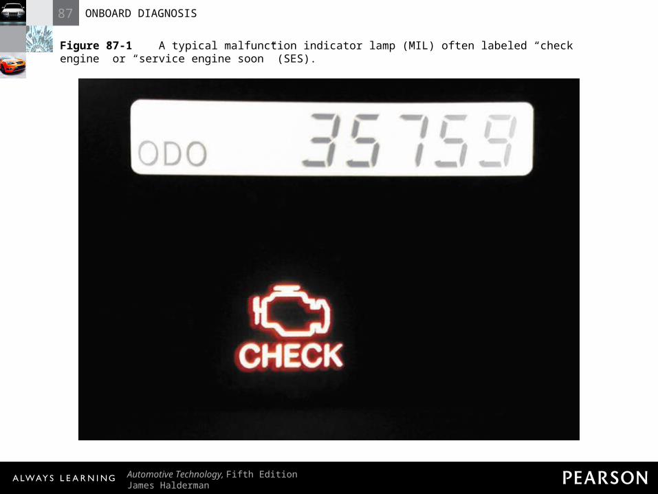
Figure 87-1 A typical malfunction indicator lamp (MIL) often labeled “check engine” or “service engine soon” (SES).
87 ONBOARD DIAGNOSIS
Automotive Technology, Fifth EditionJames Halderman
© 2011 Pearson Education, Inc.All Rights Reserved
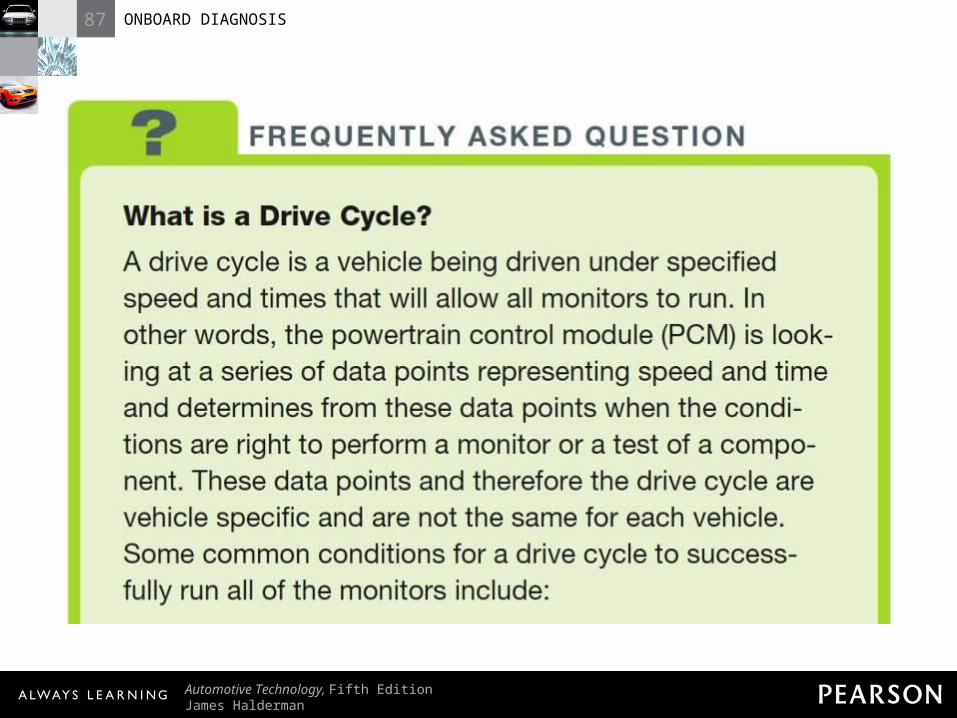
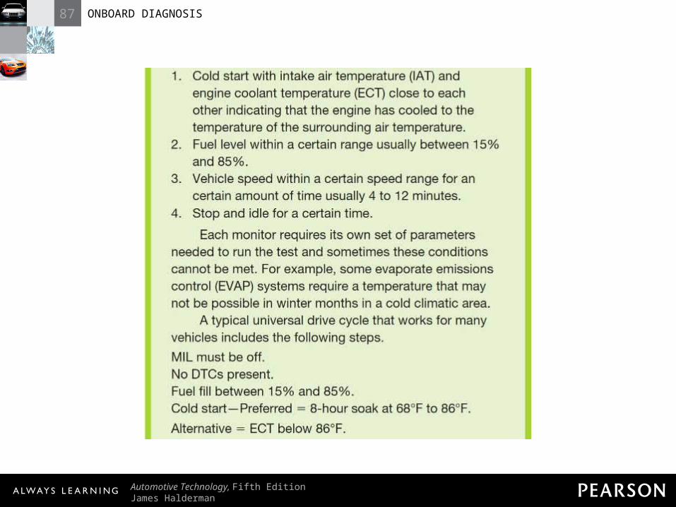
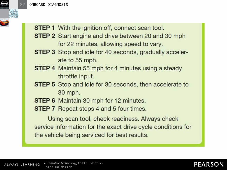
FREQUENTLY ASKED QUESTION: What is a Drive Cycle? A drive cycle is a vehicle being driven under specified speed and times that will allow all monitors to run. In other words, the powertrain control module (PCM) is looking at a series of data points representing speed and time and determines from these data points when the conditions are right to perform a monitor or a test of a component. These data points and therefore the drive cycle are vehicle specific and are not the same for each vehicle. Some common conditions for a drive cycle to successfully run all of the monitors include:1. Cold start with intake air temperature (IAT) and engine coolant temperature (ECT) close to each other indicating that the engine has cooled to the temperature of the surrounding air temperature. 2. Fuel level within a certain range usually between 15% and 85%. 3. Vehicle speed within a certain speed range for an certain amount of time usually 4 to 12 minutes. 4. Stop and idle for a certain time. Each monitor requires its own set of parameters needed to run the test and sometimes these conditions cannot be met. For example, some evaporate emissions control (EVAP) systems require a temperature that may not be possible in winter months in a cold climatic area. A typical universal drive cycle that works for many vehicles includes the following steps. MIL must be off. No DTCs present. Fuel fill between 15% and 85%. Cold start—Preferred = 8-hour soak at 68°F to 86°F. Alternative = ECT below 86°F.STEP 1 With the ignition off, connect scan tool. STEP 2 Start engine and drive between 20 and 30 mph for 22 minutes, allowing speed to vary. STEP 3 Stop and idle for 40 seconds, gradually accelerate to 55 mph. STEP 4 Maintain 55 mph for 4 minutes using a steady throttle input. STEP 5 Stop and idle for 30 seconds, then accelerate to 30 mph. STEP 6 Maintain 30 mph for 12 minutes. STEP 7 Repeat steps 4 and 5 four times. Using scan tool, check readiness. Always check service information for the exact drive cycle conditions for the vehicle being serviced for best results.
87 ONBOARD DIAGNOSIS
Automotive Technology, Fifth EditionJames Halderman
© 2011 Pearson Education, Inc.All Rights Reserved
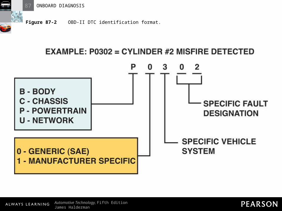
Figure 87-2 OBD-II DTC identification format.
87 ONBOARD DIAGNOSIS
Automotive Technology, Fifth EditionJames Halderman
© 2011 Pearson Education, Inc.All Rights Reserved
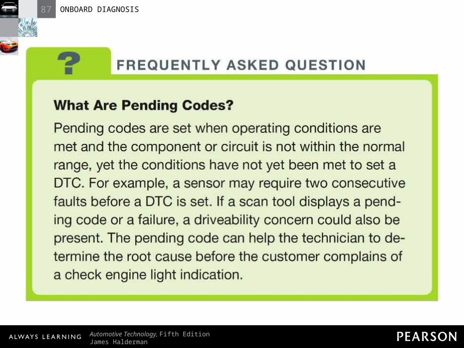
FREQUENTLY ASKED QUESTION: What Are Pending Codes? Pending codes are set when operating conditions are met and the component or circuit is not within the normal range, yet the conditions have not yet been met to set a DTC. For example, a sensor may require two consecutive faults before a DTC is set. If a scan tool displays a pending code or a failure, a driveability concern could also be present. The pending code can help the technician to determine the root cause before the customer complains of a check engine light indication.
87 ONBOARD DIAGNOSIS
Automotive Technology, Fifth EditionJames Halderman
© 2011 Pearson Education, Inc.All Rights Reserved
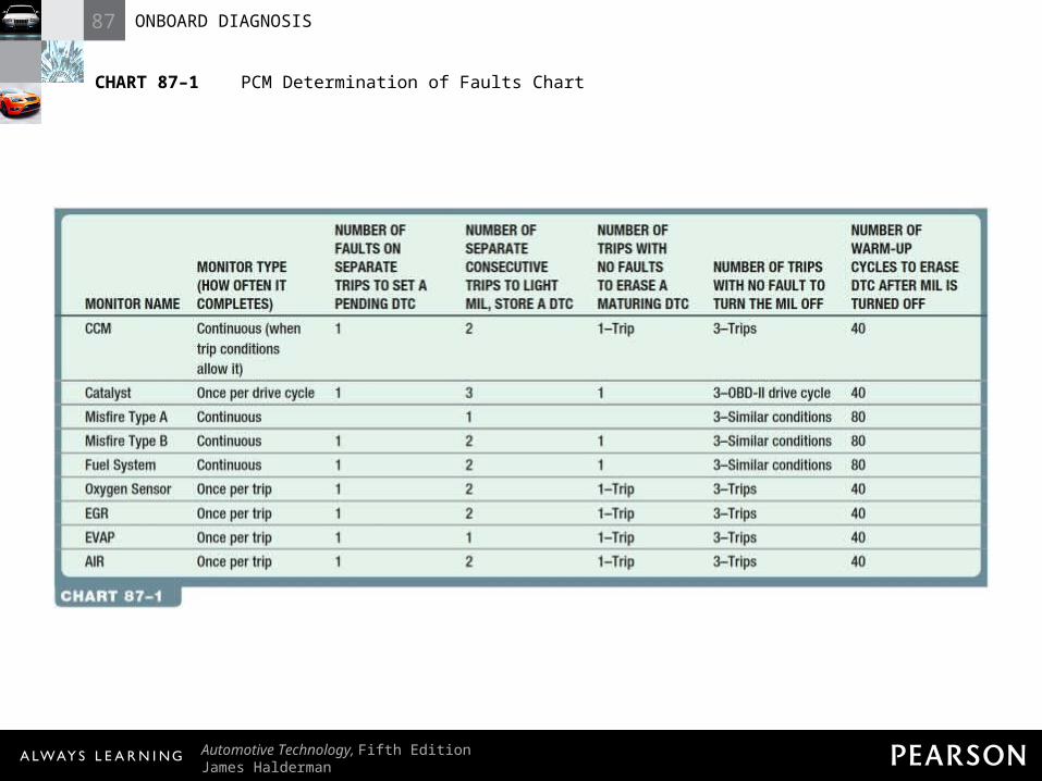
CHART 87–1 PCM Determination of Faults Chart
87 ONBOARD DIAGNOSIS
Automotive Technology, Fifth EditionJames Halderman
© 2011 Pearson Education, Inc.All Rights Reserved
FREQUENTLY ASKED QUESTION: How Can You Tell Generic from Factory? When using a scan tool on an OBD-II-equipped vehicle, if the display asks for make, model, and year, then the factory or enhanced part of the PCM is being accessed. If the generic or global part of the PCM is being scanned, then there is no need to know the vehicle identification details.