self-study programme 272 the phaeton onboard power supply
TRANSCRIPT

Service.
The PhaetonOnboard Power Supply
Design and Function
Self-Study Programme 272

2
NEW ImportantNote
The self-study programme involves the design and
function of new developments!
The contents are not updated.
Please always refer to the relevant Service Literature for all
inspection, adjustment and repair instructions.
The onboard power supply of vehicles in the early 1950s consisted of approx. 30 m of cables, some switches, lights and the ignition system.
The further development of motor vehicles required a constant increase in the number of electrical as well as electronic components.
In today's luxury performance class vehicles, the length of cable, despite networking, is approx. 3000 m, branching into approx. 1500 individual cables.
Networking connects control units with one another via databus lines. In this way, various signals can be transmitted digitally from one control unit to another. This takes place via two databus lines and eliminates the need for a separate cable for each individual signal.
This Self-Study Programme covers the design and function of the onboard power supply, that is, the power and data management of the Phaeton.
It describes new control units that control and regulate the power supply. It also describes, for example, the networking of the lighting control system as well as the CAN bus topology.
S272_073

3
Table of contents
Introduction . . . . . . . . . . . . . . . . . . . . . . . . . . . . . . . . . . . . . . 4
Electrics boxes . . . . . . . . . . . . . . . . . . . . . . . . . . . . . . . . . . . 10
Energy management. . . . . . . . . . . . . . . . . . . . . . . . . . . . . . 13
Onboard supply power management . . . . . . . . . . . . . . . . 22
Networked functions . . . . . . . . . . . . . . . . . . . . . . . . . . . . . . 30
Control unit for windscreen heating . . . . . . . . . . . . . . . . . 39
Switches . . . . . . . . . . . . . . . . . . . . . . . . . . . . . . . . . . . . . . . . 40
Dash panel insert. . . . . . . . . . . . . . . . . . . . . . . . . . . . . . . . . 46
Networking . . . . . . . . . . . . . . . . . . . . . . . . . . . . . . . . . . . . . 50
Analogue clock . . . . . . . . . . . . . . . . . . . . . . . . . . . . . . . . . . 60
Glossary . . . . . . . . . . . . . . . . . . . . . . . . . . . . . . . . . . . . . . . . 61
Test your knowledge . . . . . . . . . . . . . . . . . . . . . . . . . . . . . . 62
4
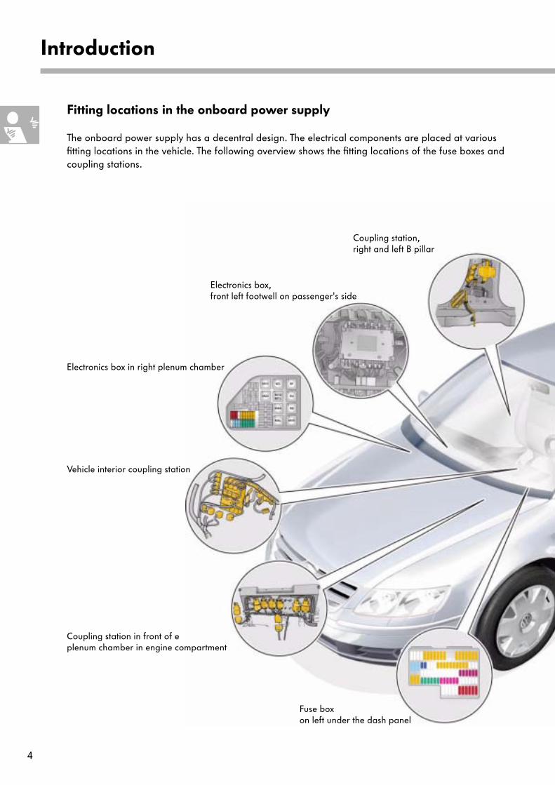
Introduction
Coupling station, right and left B pillar
Electronics box, front left footwell on passenger's side
Electronics box in right plenum chamber
Vehicle interior coupling station
Coupling station in front of e plenum chamber in engine compartment
Fuse box on left under the dash panel
Fitting locations in the onboard power supply
The onboard power supply has a decentral design. The electrical components are placed at various fitting locations in the vehicle. The following overview shows the fitting locations of the fuse boxes and coupling stations.

5
S272_009
Coupling station, right and left A pillars
Thermo-fuse box in front left footwell
Coupling station, right and left C pillars
Electronics box on left of boot
Back-up fuse boxon left of boot

6
Introduction
Electronics box in the left of boot
Connection point, rear bumper
Connection point,trailer towbar
Connection point, control units under rear shelf
Coupling station, right and left C pillars
Onboard power supply battery
Starter battery
Main wiring harness
Engine wiring harness
Gearbox wiring harness
Cable routing
The main wiring harness runs from the battery in the boot on the driver's side to the connection points. In the case of vehicles with a two-battery onboard power supply, the starter motor is supplied via a separate wiring harness on the right-hand side. For protection, the wiring harnesses are laid in the floorpan area in cable ducts.

7
S272_051
Connection point, headlights, additional heating
Connection point for control unit for anti-lock braking system/Electronic Stability Programme
Coupling station in front of plenum chamber in engine compartment
Fuse box on left under dash panel
Electronics box in right plenum chamber
Connection point, control unit for front passenger's seat
Electronics box in front right footwell
Connection point, engine compartment
Control unit for engine electronicsControl unit for gearbox electronics
Coupling station, right A pillar
Thermo-fuse box in left footwell
Connection point, control unit for driver's seat
Connection points, dash panel insert andvehicle interior
Coupling station, left B pillar
Coupling station, left A pillar
Connection point, front bumper
Connection point, headlights
Coupling station, right B pillar
Front information display and operating unit

8
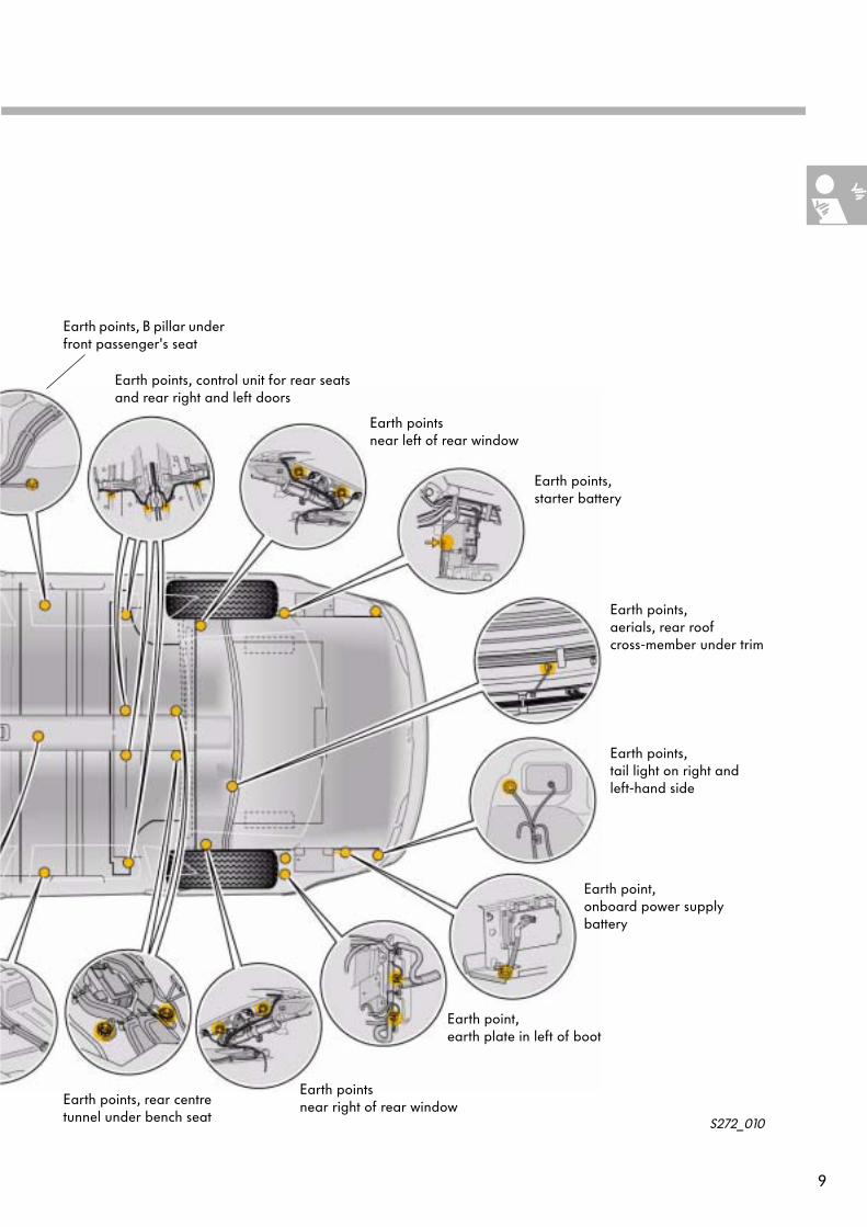
Earth points
Specially selected locations in the vehicle serve as Earth points, as they are essential on modern vehicles with a large number of high-quality electronic control units.
The electronics are dependent on equalised earth potential to be able to work faultlessly. Randomly selected Earth points can lead to different earth potentials and may cause malfunctions (e.g. compensating currents).
Introduction
Earth point, airbag control unit
Earth point, left A pillar
Earth points, left engine bulkhead
Earth pointsEngine compartment, left
Earth points at front right,near horn
Earth points, right engine compartment
Earth points, right engine bulkhead
Earth points, air conditioning system/DSP
Earth point, onboard power supply control unit
Earth points, driver's seat
9
S272_010
Earth points, control unit for rear seats and rear right and left doors
Earth pointsnear left of rear window
Earth points, starter battery
Earth points, aerials, rear roof cross-member under trim
Earth points, tail light on right and left-hand side
Earth point, onboard power supply battery
Earth point, earth plate in left of boot
Earth pointsnear right of rear windowEarth points, rear centre
tunnel under bench seat
Earth points, B pillar under front passenger's seat
10
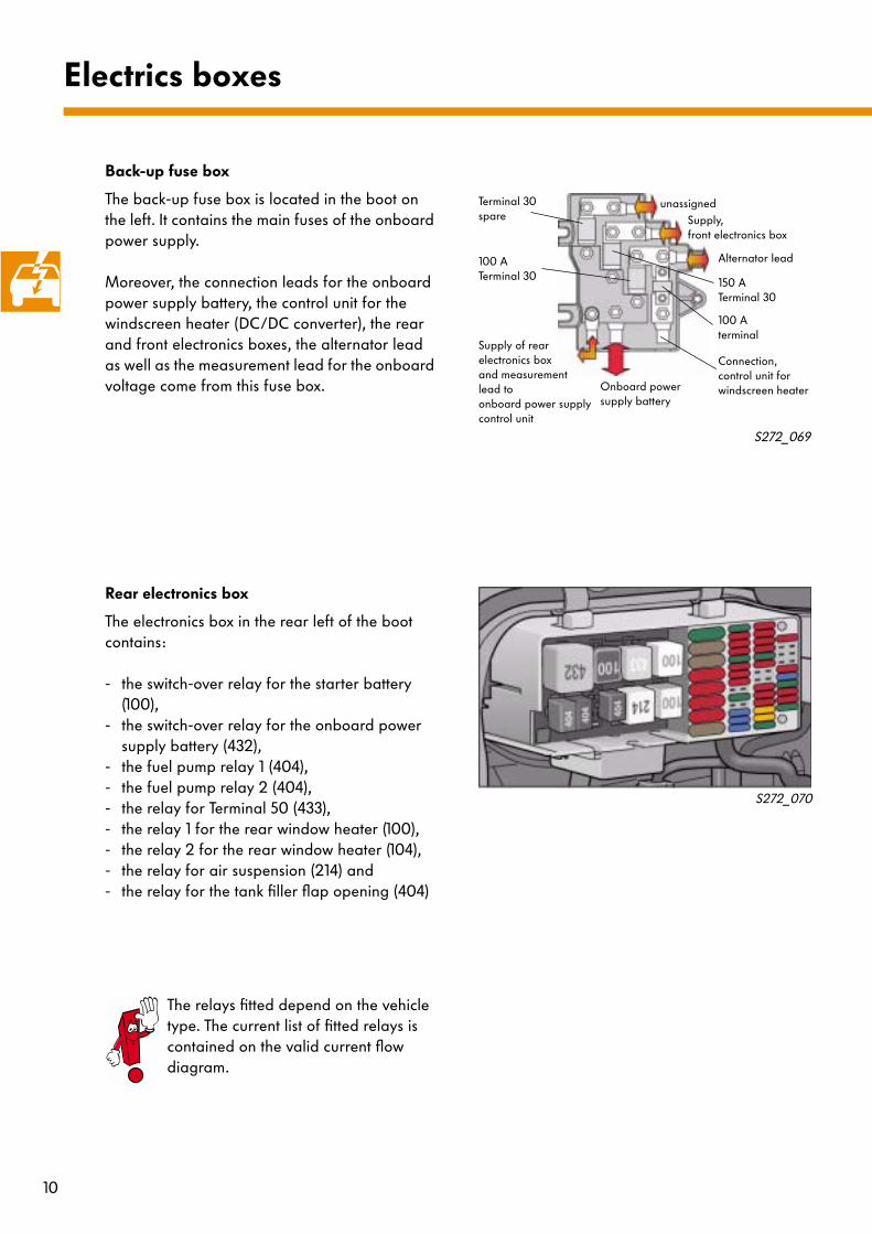
Back-up fuse box
The back-up fuse box is located in the boot on the left. It contains the main fuses of the onboard power supply.
Moreover, the connection leads for the onboard power supply battery, the control unit for the windscreen heater (DC/DC converter), the rear and front electronics boxes, the alternator lead as well as the measurement lead for the onboard voltage come from this fuse box.
Rear electronics box
The electronics box in the rear left of the boot contains:
- the switch-over relay for the starter battery (100),
- the switch-over relay for the onboard power supply battery (432),
- the fuel pump relay 1 (404),- the fuel pump relay 2 (404),- the relay for Terminal 50 (433),- the relay 1 for the rear window heater (100),- the relay 2 for the rear window heater (104),- the relay for air suspension (214) and- the relay for the tank filler flap opening (404)
Electrics boxes
S272_069
S272_070
unassignedSupply, front electronics box
Alternator lead
Onboard power supply battery
Supply of rear electronics box and measurement lead to onboard power supply control unit
Terminal 30spare
150 A Terminal 30
100 ATerminal 30
100 A terminal
The relays fitted depend on the vehicle type. The current list of fitted relays is contained on the valid current flow diagram.
Connection, control unit for windscreen heater

11
Electronics box, plenum chamber
Components
- Smoothing capacitor for onboard power supply voltage
- Main relays 1 and 2 (53 and 100)- Terminal 75 relay (100)- Terminal 15 relay (433)- Secondary air pump relays 1 and 2 (100)
as well as- Power supply relay for Motronic (167)are located in the electronics box in the front plenum chamber.
Thermo-fuse box
The thermo-fuse box in the front left footwell contains the thermo-fuses:
- left window regulator 30 A- right window regulator 30 A- driver's seat control unit 30 A- front passenger's seat control unit 30 A- rear compartment seat control unit 30 A- rear left PTC heating 30 A- rear right PTC heating 30 A
S272_071
Capacitor
S272_077
Thermo-fuses
Control unit for entry and start authorisation
The thermo-fuses fitted depend on the vehicle type. The current list of fitted thermo-fuses are contained on the valid current flow diagram.
12
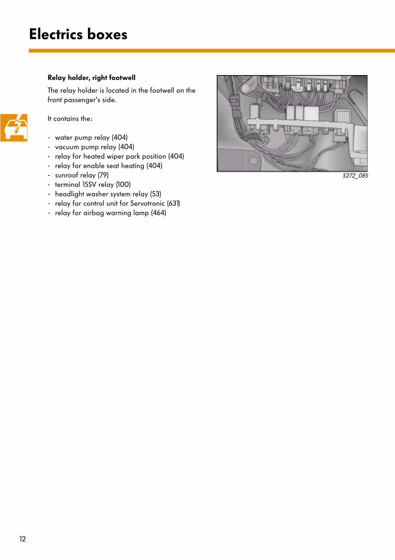
Relay holder, right footwell
The relay holder is located in the footwell on the front passenger's side.
It contains the:
- water pump relay (404)- vacuum pump relay (404)- relay for heated wiper park position (404)- relay for enable seat heating (404)- sunroof relay (79)- terminal 15SV relay (100)- headlight washer system relay (53)- relay for control unit for Servotronic (631)- relay for airbag warning lamp (464)
Electrics boxes
S272_085

13
In order to ensure sufficient power supply of the electrical equipment and the starter motor, a
- one-battery onboard power supply
as well as a
- two-battery onboard power supply
are used.
In case of vehicles with one-battery onboard power supplies, it ensures the supply of electrical energy.
Vehicles with two-battery onboard power supplies have a starter battery and an onboard power supply battery. In normal operation, the starter battery supplies the starter motor during the starting cycle and the onboard power supply battery supplies the electrical equipment. If one of the batteries does not have sufficient power, it is supported by the other. Support is controlled by the control unit for battery monitoring.
Power management
Engine Onboard power supply battery
Starter battery
V6 75 Ah/420 A* 61 Ah/330 A**
V8 75 Ah/420 A* 61 Ah/330 A**
W12 85 Ah/480 A 61 Ah/330 A
V10 TDI 85 Ah/480 A 85 Ah/480 A
*currently still 85 Ah/450 A The 75 Ah/420 A battery will be deployed later.
**optional
S272_012
S272_013
Back-up fuse box
Battery
Onboard power supply battery
Control unit for battery monitoring
Starter battery
Back-up fuse box
Relay for parallel switching of batteries

14
To ensure the power supply for the electrical equipment on the W12 and V10 TDI, the two-battery onboard power supply is used; for all other versions, it is available as an option.
Components
●
Starter battery
●
Onboard power supply battery
●
Relay for parallel switching of batteries
●
switch-over relay for starter battery
●
switch-over relay for onboard power supply battery
●
Control unit for battery monitoring
●
Temperature sensor for starter battery
Functional description
Normally, the starter battery supplies the starting circuit of the engine. The onboard power supply battery supplies the 12-volt onboard power supply; in the case of a cold start, it is supported by the starter battery.
The circuit of the starter motor and onboard power supply electrical circuit are controlled by the control unit for battery monitoring (J367). This controls the charge of the starter battery and safely ensures supply of the electrical equipment required to start the car.
Energy management
S272_072
Relay for parallel switching
Switch-over relay S
Switch-over relay BData transfer via CAN bus e.g.
from control unit for entry and start authorisation
Starter motor
Starter battery Supply Control unit for battery monitoring (J367) on left of boot
Onboard power supply battery
A1 T. 50A4 Key-InA14 Terminal 15A15 Emergency mode
A17 T. 30A18 T.l 15SV
Temperature sensor
Terminal 30SV
Terminal 30
15
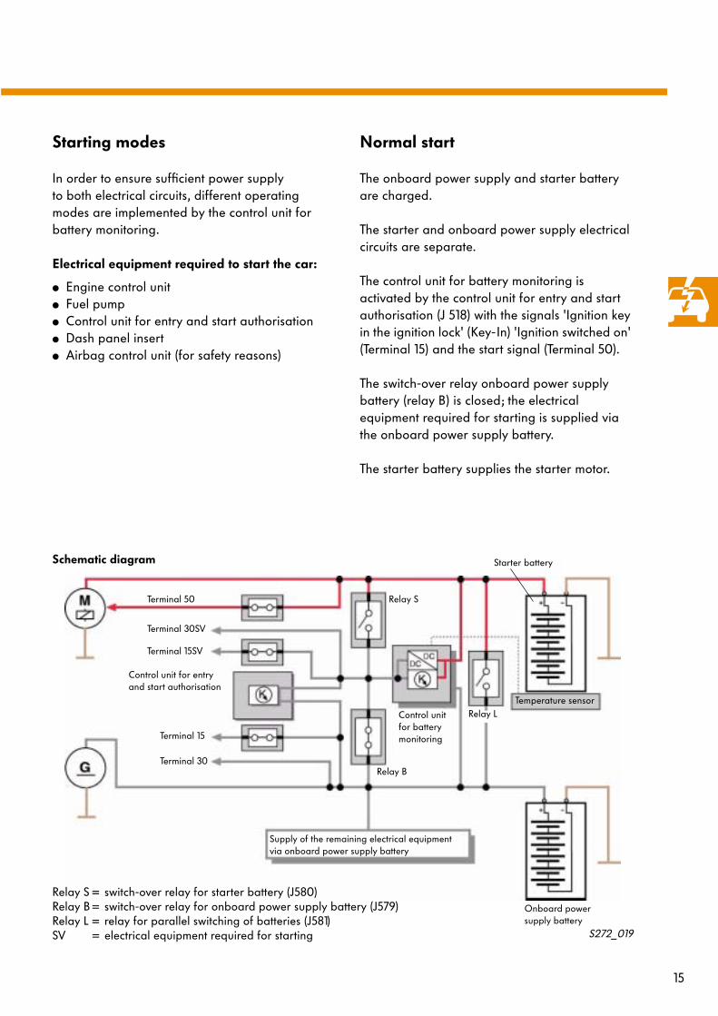
Starting modes
In order to ensure sufficient power supply to both electrical circuits, different operating modes are implemented by the control unit for battery monitoring.
Electrical equipment required to start the car:
●
Engine control unit
●
Fuel pump
●
Control unit for entry and start authorisation
●
Dash panel insert
●
Airbag control unit (for safety reasons)
Normal start
The onboard power supply and starter battery are charged.
The starter and onboard power supply electrical circuits are separate.
The control unit for battery monitoring is activated by the control unit for entry and start authorisation (J 518) with the signals 'Ignition key in the ignition lock' (Key-In) 'Ignition switched on' (Terminal 15) and the start signal (Terminal 50).
The switch-over relay onboard power supply battery (relay B) is closed; the electrical equipment required for starting is supplied via the onboard power supply battery.
The starter battery supplies the starter motor.
S272_019
Supply of the remaining electrical equipment via onboard power supply battery
Starter battery
Onboard power supply battery
Temperature sensor
Relay S = switch-over relay for starter battery (J580)Relay B= switch-over relay for onboard power supply battery (J579)Relay L = relay for parallel switching of batteries (J581)SV = electrical equipment required for starting
Terminal 50
Terminal 30SV
Terminal 15SV
Terminal 15
Terminal 30
Control unit for entry and start authorisation
Relay B
Relay S
Relay LControl unit for battery monitoring
Schematic diagram
16
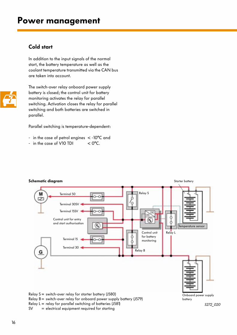
Cold start
In addition to the input signals of the normal start, the battery temperature as well as the coolant temperature transmitted via the CAN bus are taken into account.
The switch-over relay onboard power supply battery is closed; the control unit for battery monitoring activates the relay for parallel switching. Activation closes the relay for parallel switching and both batteries are switched in parallel.
Parallel switching is temperature-dependent:
- in the case of petrol engines < -10°C and- in the case of V10 TDI < 0°C.
Power management
Starter battery
Temperature sensor
Terminal 50
Terminal 30SV
Terminal 15SV
Terminal 15
Terminal 30
Relay S
Relay L
Onboard power supply battery
Schematic diagram
S272_020
Control unit for entry and start authorisation
Control unit for battery monitoring
Relay B
Relay S = switch-over relay for starter battery (J580)Relay B= switch-over relay for onboard power supply battery (J579)Relay L = relay for parallel switching of batteries (J581)SV = electrical equipment required for starting

17
The starting cycle in the case of discharged onboard power supply battery
With Terminal 15SV switched on, the 'Emergency start' mode is sent via the CAN bus and the PIN 'Emergency operation' if the voltage of the onboard power supply battery is less than 11 V.
Terminal 30SV is connected via the switch-over relay starter battery to the starter battery as soon as the ignition key is inserted in the ignition lock.
When the ignition is turned on, the Drive Train CAN bus goes to partial operation. Only control units required for starting take part in the communication.
After the engine starts, heating equipment involved in the convenience system is switched off for two to five minutes.
The 'Emergency operation' mode is cancelled approx. two seconds after the system detects that the engine is running.
Until there is sufficient charge voltage in the onboard power supply battery, the onboard power supply is supplied from the starter battery by means of parallel switching via the relay for parallel switching.
In the case of diesel engines, the connection to the starter battery is made when Terminal15SV it is switched to enable the glow phase.
Starter battery
Temperature sensor
Terminal 50
Terminal 30SV
Terminal 15SV
Terminal 15
Terminal 30
Relay S
Relay L
Onboard power supply battery
Schematic diagram
S272_021
Control unit for entry and start authorisation
Control unit for battery monitoring
Relay B
Relay S = switch-over relay for starter battery (J580)Relay B= switch-over relay for onboard power supply battery (J579)Relay L = relay for parallel switching of batteries (J581)SV = electrical equipment required for starting
18
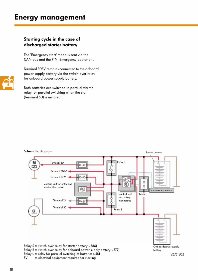
Starting cycle in the case of discharged starter battery
The 'Emergency start' mode is sent via the CAN bus and the PIN 'Emergency operation'.
Terminal 30SV remains connected to the onboard power supply battery via the switch-over relay for onboard power supply battery.
Both batteries are switched in parallel via the relay for parallel switching when the start (Terminal 50) is initiated.
Energy management
Starter battery
Temperature sensor
Terminal 50
Terminal 30SV
Terminal 15SV
Terminal 15
Terminal 30
Relay S
Relay L
Onboard power supply battery
Schematic diagram
S272_022
Control unit for entry and start authorisation
Control unit for battery monitoring
Relay B
Relay S = switch-over relay for starter battery (J580)Relay B= switch-over relay for onboard power supply battery (J579)Relay L = relay for parallel switching of batteries (J581)SV = electrical equipment required for starting

19
Monitoring after a crash event
In the case of a crash event, the control unit for battery monitoring receives a crash signal via the CAN bus. This cancels the charge operation of the starter battery. This signal remains stored until it is reset by the VAS 5051 Diagnostic Testing and Information System. Every time the ignition is switched on, the lead to the starter motor is tested for short circuits.
If a short circuit is detected, it prevents a starting cycle from initiating.
If the 'Key IN' is not present and the onboard power supply battery is discharged, no start is possible.The VAS 5051 Diagnostic Testing And Information System can be used to diagnose the control unit for battery monitoring.
Starter battery
Temperature sensor
Terminal 50
Terminal 30SV
Terminal 15SV
Terminal 15
Terminal 30 Relay B
Relay S
Relay L
Onboard power supply battery
Schematic diagram
S272_068
Control unit for entry and start authorisation
Control unit for battery monitoring
Crash signal via CAN bus
Relay S = switch-over relay for starter battery (J580)Relay B= switch-over relay for onboard power supply battery (J579)Relay L = relay for parallel switching of batteries (J581)SV = electrical equipment required for starting

20
Energy management
Alternator
A liquid-cooled alternator with 190 Amperes is fitted. Its maximum current in the short term can be up to 300 Amperes.
The alternator contains six instead of three stator windings, which are excited via a winding in the rotor. The drive on the V10 TDI is via an internal shaft and a gear.
Smoothing capacitor for the onboard power supply voltage
The onboard power supply battery is located in the boot. The length of the charge lead from the alternator to the battery is approx. 6 m. The capacitor has the task of reducing the voltage ripple on the charge lead in the vicinity of the alternator. Smoothing the charge current and charge voltage on the charge lead reduces electrical and acoustic faults. The supply for the high-current electrical equipment, where high voltage ripples can occur, is tapped in the plenum chamber.
S272_080
Exit Entry
Terminal LTerminal DF
Terminal B+
Liquid
S272_025
S272_024
Electronics box, plenum chamber
Onboard power supply electrical equipment
Vehicle electrical system battery
Legend
C - CapacitorE - Exciter winding in the rotorTerminal B+ - Battery positiveTerminal DF - Dynamo fieldTerminal L - Signal wiring for warning lamp in
dash panel insertU, V, W, X, Y, Z - Winding ends of
the generating coil
Control

21
Charge process of the starter battery
The charging process of the starter battery can take place in two operating modes:
- through the transistoror
- the DC/DC converter in the control unit for battery monitoring.
As long as the nominal charge voltage of the starter battery is lower than the current onboard power supply voltage, the charge current of the starter battery is fed via the transistor.
If the onboard power supply voltage is below the nominal value of the charge voltage, the charge current is fed via the DC/DC converter. The charge time is monitored by the control unit for battery monitoring. If the starter battery does not reach its voltage value within the prescribed parameter, the charging process is cancelled and disabled. This means that a defective battery is not continuously charged.
A fault is entered in the fault memory: charge monitoring for starter battery - upper limit value exceeded.
The control unit for battery monitoring has diagnostic capability with the VAS 5051 Diagnostic Testing and Information System.
Starter battery
Temperature sensor
Terminal 50
Terminal 30SV
Terminal 15SV
Terminal 15
Terminal 30
Relay S
Relay L
Onboard power supply battery
Schematic diagram
S272_023
Control unit for entry and start authorisation
Control unit for battery monitoring
Relay B
Relay S = switch-over relay for starter battery (J580)Relay B= switch-over relay for onboard power supply battery (J579)Relay L = relay for parallel switching of batteries (J581)SV = electrical equipment required for starting

22
The onboard power supply control unit (J519) pools various functions in the vehicle.
The various functions that until now were enabled via switches and relays
- Parking lights- Dipped beam headlights- Side lights- Turn indicators- Main beam headlights - Fog lights- Footwell lights- Terminal 58 d- Indicator lamp for hazard warning lights- Relay for headlight washer system- Relay for heating wiper park position- Fuel pump feed and- Hornare switched by the onboard power supply control unit.
Front of device connector
Back of device connector
The onboard power supply control unit is located in the electronics box in the right-hand footwell.
Onboard power supply management
S272_053
S272_055
A B C D E F G
S272_054
H J K L M N P

23
Supply voltage
CAN bus signals
Input signals
Signal Input from Output to
Voltage of onboard power supply battery Onboard power supply battery +
Voltage of starter battery Starter battery +
Voltage of starter battery Starter battery -
Voltage of onboard power supply battery Onboard power supply battery -
Terminal 15 Control unit for entry and start authorisation
Signal Input from Output to
Convenience CAN High Convenience CAN bus Convenience CAN bus
Convenience CAN Low Convenience CAN bus Convenience CAN bus
Signal Input from Output to
Hazard warning lights Button for hazard warning lights
Fog lights Button for fog lights
Automatic lights Light switch
Mirror heating Switch for door mirror
Dimming Increase dimmer +
Dimming Reduce dimmer -
Fault fibre-optic cable Headlight, right
Mirror adjustment Switch for door mirror
Fold-in mirror Switch for door mirror
Bonnet opened Switch for bonnet
Side lights Light switch
Rear fog light Light switch
Dipped beam headlights Light switch
Reversing light Switch for reversing light
Mirror adjustment GND switch for door mirror
Fog lights Terminal 30 fuse box
Low-beam and main beam headlight, left Terminal 30 fuse box

24
Input signal (continued)
Output signals
Signal Input from Output to
Low-beam and main beam headlight, left Terminal 30 fuse box
Flashing light, left side light Terminal 30 fuse box
Low-beam and main beam headlight, right Terminal 30 fuse box
Flashing light, right side light Terminal 30 fuse box
Horn Terminal 30 fuse box
Wake up running gear Running gear control
Footwell lights Terminal 58d
Headlight washer system Terminal 30 fuse box
Signal Input from Output to
Fog lights Fog lights
Footwell lighting Footwell lights
Instrument lighting Terminal 58d Instrument
Turn signal, left Headlight, left
Main beam headlight, left Headlight, left
Dipped beam headlight, left Headlight, left
Parking light, left Headlight, left
Main beam headlight, right Headlight, right
Dipped beam headlight, right Headlight, right
Turn indicator, right Headlight, right
Parking light, right Headlight, right
Horn Horn
Check of hazard warning lights Indicator lamp
Heating Wiper storage relay
Headlight washer system HWS pump
Supply line, fuel pump Fuel pump relay
Enable seat heater Relay (only in the case of veh. without seat memory control unit)
Headlight cleaning system Pop-up washer jet motor, right
Headlight washer system Pop-up washer jet motor, left
Voltage supply + Terminal 30a
Onboard power supply management

25
Special features of the lighting control system
Turn indicators
The following turn indicator controls are possible:
●
Turn indication
●
Hazard warning lights
●
Crash indication
●
Flashing on locking and activating the anti-theft alarm system as well as panic flashing (USA only)
The onboard power supply control unit also controls the onboard power supply management so that sufficient electrical energy is available continuously.
The onboard power supply management switches off electrical equipment if the battery voltage of the onboard power supply battery falls below a defined value.
Side lights and driving lights
Emergency function
An additional circuit in the onboard power supply control unit ensures that the side lights and dipped beam headlights are also switched on in the case of a defect in the onboard power supply control unit.
If a turn indicator light fails, the rate of the indicator lamp is doubled to signal the failure. The indicator lights continue to work at the normal rate. With the hazard warning lights, the indicator lamp flashes at the normal rate.
These operating modes are arranged by priority:
1 Crash indication
2 Hazard warning lights
3 Turn indication
4 Special functions, e.g. anti-theft alarm system
With this arrangement, a flashing function can be activated although another has not been deactivated.
Via the VAS 5051 Diagnostic Testing And Information System, the onboard power supply control unit has diagnostic capability.

26
Monitoring the onboard power supply voltage
The onboard power supply control unit monitors the charge state of the onboard power supply battery to avoid excessive discharge.
From the alternator (Terminal DF), the engine control unit receives the pulse-width modulated (PWM) information regarding the capacity utilisation of the alternator. This information reaches the Convenience CAN bus via the Drive Train CAN bus and the gateway in the dash panel insert. The onboard power supply control unit evaluates the state of the onboard power supply voltage by comparing the DF signal and the onboard power supply voltage.
If a critical state of the onboard power supply is detected, the idling speed is increased; in very critical states, convenience electrical equipment is switched off.
Onboard power supply management
The dynamo field signal can be shown using the VAS 5051 Diagnostic Testing and Information System.
S272_018
Engine control unit
DF signal
Drive Train CAN bus
Onboard power supply control unit
Convenience CAN bus
Battery voltage
Gateway

27
Raising the idling speed
If the voltage of the onboard power supply battery falls below 12.7 volts for longer than 10 seconds, the state of the onboard power supply is classified as critical and the idling speed is raised. The signal for requesting a rise is sent by the onboard power supply control unit via the Convenience CAN bus, the gateway and the Drive Train CAN bus to the engine control unit.
The idling speed is raised when the automatic gearbox is in positions 'P' or 'N'. It remains at the increased level if - on transition to vehicle operation - the engine speed was higher beforehand.
S272_014
Engine control unit
Idling speed increase Battery voltageDF signal
Onboard power supply control unit
The value of the speed increase varies from one engine variant to the next.
If the voltage is constantly higher than 12.7 volts for at least two seconds, the state of the onboard power supply is detected as uncritical and the request to raise the idling speed is cancelled.
Modifying the engine speed is regulated by the engine control unit according to defined values. Fluctuations in engine speed due to fluctuating voltage values are largely suppressed by the engine control unit.
Gateway
Drive Train CAN bus Convenience CAN bus