oil/water separators - comp-air southwest inc
TRANSCRIPT
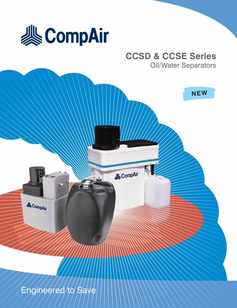
Engineered to Save
CCSD & CCSE SeriesOil/Water Separators
NEW
Oil/Water Separators
Condensate generated by lubricated type aircompressors is comprised of atmospheric borne water vapor and lubricant from the compression process. Post compression, condensate is dropped from the air stream in the cooling, refrigerated dryer, and filtration phases of the air treatment process. Regardless of site conditions, it is virtually impossible to remain legally compliant with local discharge regulations without proper separation equipment.
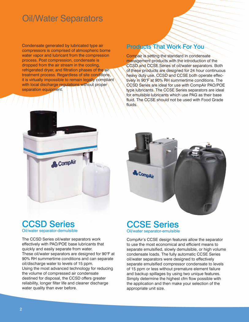
CCSD SeriesOil/water separator-demulsible
The CCSD Series oil/water separators work effectively with PAO/POE base lubricants that quickly and easily separate from water. These oil/water separators are designed for 90°F at 90% RH summertime conditions and can separate oil/discharge water to levels of 15 ppm. Using the most advanced technology for reducing the volume of compressed air condensate destined for disposal, the CCSD offers greater reliability, longer filter life and cleaner discharge water quality than ever before.
Products That Work For YouCompair is setting the standard in condensatemanagement products with the introduction of the CCSD and CCSE Series of oil/water separators. Both of these products are designed for 24 hour continuous heavy duty use. CCSD and CCSE both operate effec-tively in 90°F at 90% RH summertime conditions. The CCSD Series are ideal for use with CompAir PAO/POE type lubricants. The CCSE Series separators are ideal for emulsible lubricants which use PAG as their base fluid. The CCSE should not be used with Food Grade fluids.
CCSE SeriesOil/water separator-emulsible
CompAir’s CCSE design features allow the separator to use the most economical and efficient means to separate emulsified, slowly demulsible, or high volume condensate loads. The fully automatic CCSE Series oil/water separators were designed to effectively separate emulsified compressor condensate to levels of 15 ppm or less without premature element failure and backup spillages by using two unique features. Simply determine the highest cfm flow possible with the application and then make your selection of the appropriate unit size.
2
Product Features
CCSD Features Effective Design
• Removable Sediment Chamber prevents rust, dirt and scale from escaping into the main reservoir
• Internal filter inside Sediment Chamber accelerates the coalescing process by making fine oil droplets larger resulting in faster separation
• Timely piping removal is eliminated due to the accessibility of the Access Lid
• Replaceable pre-absorber possesses a proprietary, non-restrictive, polar absorber which extends life of the carbon bed
• Pop-up flow indicator
• Three input connections
• Integrated handles for ease of filter replacement
Reliability and Effectiveness• Designed for 24/7/365 operation
• Designed for 90°F at 90% RH conditions
• Oil Outlet Weir prevents spills by allowing the amount of oil collected to be seen.
• Sample Valve eliminates guesswork on when filters need changed, saving time and money.
Options• Heaters: Used in areas where the separator
might be subject to freezing temperatures.
• Distributor: Used to collect and evenly distribute flow into multiple units; also recommended for use with high capacity demand drains to protect the CCSD from large condensate surges. Distributor is available on CCSD120–240.
CCSE Features Unique Delivery System
• Pneumatically operated pump that feeds the filter module—no electricity needed.
• Two moving parts ensure maximum reliability.
• Filter module contains a proprietary blend of alumino silicate and carbon. Alumino silicate substrate is coated with a hydrophobic compound, resulting in the media’s ability to hold up to four times the amount of oil that standard activated carbon can hold.
• Availability of three different sized filter modules make your system easily expandable.
• Filter is completely self-contained and easily transported.
3
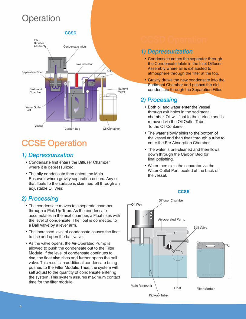
InletDiffuserAssembly
Flow Indicator
Carbon Bed Oil Container
SampleValve
Oil Outlet Tube
Pre-AbsorptionChamber
Suspended CarbonBed Handles
Vessel
Water Outlet Port
SedimentChamber
Separation Filter
Condensate Inlets
CCSD
CCSE
Operation
CCSE Operation1) Depressurization
• Condensate first enters the Diffuser Chamber where it is depressurized.
• The oily condensate then enters the Main Reservoir where gravity separation occurs. Any oil that floats to the surface is skimmed off through an adjustable Oil Weir.
2) Processing• The condensate moves to a separate chamber
through a Pick-Up Tube. As the condensate accumulates in the next chamber, a Float rises with the level of condensate. The float is connected to a Ball Valve by a lever arm.
• The increased level of condensate causes the float to rise and open the ball valve.
• As the valve opens, the Air-Operated Pump is allowed to push the condensate out to the Filter Module. If the level of condensate continues to rise, the float also rises and further opens the ball valve. This results in additional condensate being pushed to the Filter Module. Thus, the system will self adjust to the quantity of condensate entering the system. This system assures maximum contact time for the filter module.
Diffuser Chamber
Pick-up Tube
Oil Weir
Main ReservoirFloat
Air-operated Pump
Filter Module
Ball Valve
CCSD Operation1) Depressurization
• Condensate enters the separator through the Condensate Inlets in the Inlet Diffuser Assembly where air is exhausted to atmosphere through the filter at the top.
• Gravity draws the new condensate into the Sediment Chamber and pushes the old condensate through the Separation Filter.
2) Processing• Both oil and water enter the Vessel
through exit holes in the sediment chamber. Oil will float to the surface and is removed via the Oil Outlet Tube to the Oil Container.
• The water slowly sinks to the bottom of the vessel and then rises through a tube to enter the Pre-Absorption Chamber.
• The water is pre-cleaned and then flows down through the Carbon Bed for final polishing.
• Water then exits the separator via the Water Outlet Port located at the back of the vessel.
4

Water Outlet Port“G” NPT
Sample Jars (2)
Condensate Inlets (3) ½ NPT
Oil Outlet Tube
2½ Gallon Oil Container (CCSD15)5 Gallon Oil Container (CCSD30 through CCSD240)
Water Sample Valve
Diuser(see note 3) Carbon Chamber
Access Lid
Flow Indicator
DIMENSIONAL SYMBOL
Size A B C D E F G H J K L M N P Q R
CCSD15 29.75 27.00 20.75 11.25 5.25 16.00 .75 26.50 26.00 9.00 14.00 19.50 4.50 2.75 4.50 4.00
CCSD30 39.00 36.25 29.75 17.00 6.25 22.75 .75 34.00 32.00 12.50 15.00 21.00 7.50 3.50 6.50 5.25
CCSD60 39.00 36.25 29.75 17.00 5.25 23.00 1.00 35.00 32.00 22.00 26.50 30.75 6.00 3.50 13.50 5.25
CCSD120 39.00 36.25 29.75 17.00 5.25 23.00 1.00 72.00 32.00 22.00 26.50 30.75 6.00 3.50 13.50 5.25
CCSD180 39.00 36.25 29.75 17.00 5.25 23.00 1.00 109.00 32.00 22.00 26.50 30.75 6.00 3.50 13.50 5.25
CCSD240 39.00 36.25 29.75 17.00 5.25 23.00 1.00 146.00 32.00 22.00 26.50 30.75 6.00 3.50 13.50 5.25
NOTE 1: All dimensions are in inches.NOTE 2: Tolerances-all dimensions are +/- .50 unless otherwise shown.NOTE 3: Diffuser is rotatable in 90 degree increments.
CCSD Dimensional Data
5
19.5
9.8
9.8
29.5
4.7
5.8
9.4
"B"
"B"
Control AirInlet Filter1/4 FNPT
Oil Outlet3/4" BARB FTG
Access Lid
Condensate to ModuleOutlet Connection
1/4 FNPT
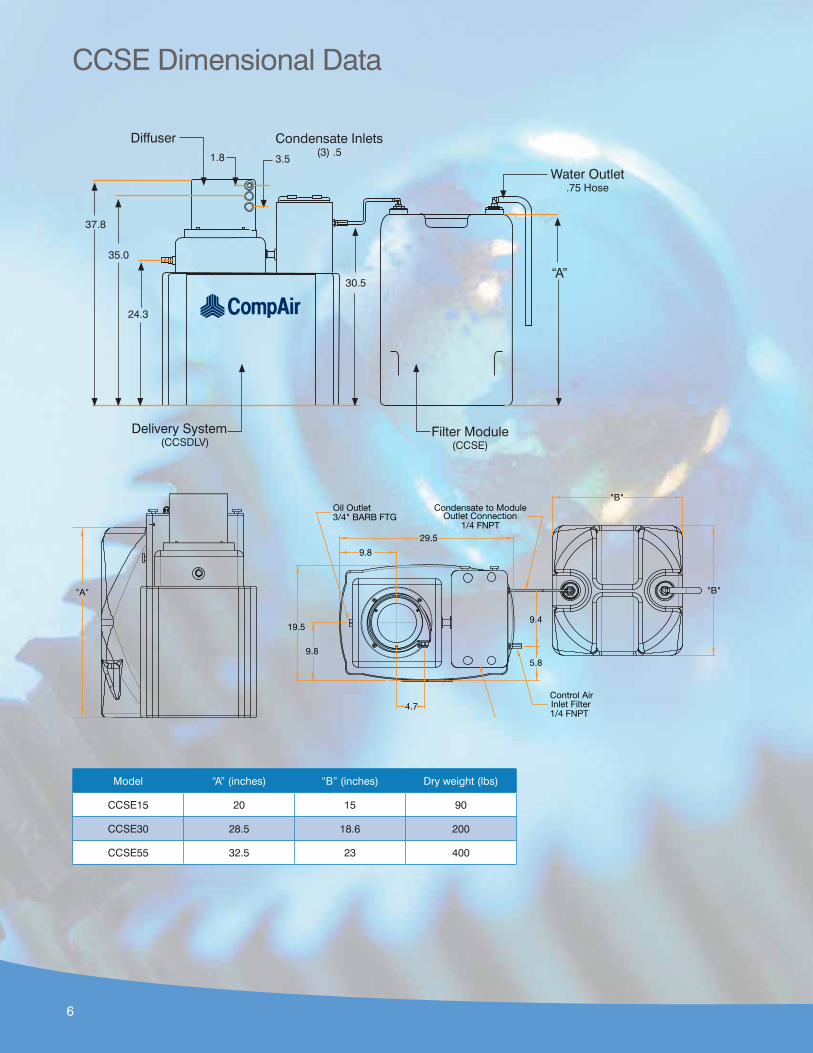
Model “A” (inches) “B” (inches) Dry weight (lbs)
CCSE15 20 15 90
CCSE30 28.5 18.6 200
CCSE55 32.5 23 400
CCSE Dimensional Data
37.8
35.0
1.8
24.3
Delivery System(CCSDLV)
Diffuser Condensate Inlets(3) .5
Water Outlet.75 Hose
Filter Module(CCSE)
30.5“A”
"A"
3.5
6

CCSD Ordering Information
ModelMax. CFM Capacity** Dimensions (inches) Inlet Water
Outlet
OilContainer Weight
90˚F @ 90% RH 70˚F @ 70% RH H D W NPT gal lbs
CCSD15 150 357 30 19 26.5 (3) ½" ¾" 2.5 53
CCSD30 300 714 39 21 34 (3) ½" ¾" 5 77
CCSD60 600 1428 39 31 35 (3) ½" 1" 5 120
CCSD120 1200 2856 39 31 72 (3) ½" (2) 1" (2) 5 240
CCSD180 1800 4284 39 31 109 (3) ½" (3) 1" (3) 5 360
CCSD240 2400 5712 39 31 146 (3) ½" (4) 1" (4) 5 480
*Optional distributor ports available for CCSD120-240**Optional heaters available for CCSD15-240
CCSE Ordering InformationModel Delivery System cfm Filter Gallons
CCSE15 125–250 15
CCSE30 250–500 30
CCSE55 560–1125 55
Filter Replacements
Part # Description
CCSFM15 Filter Module, CCSE15
CCSFM30 Filter Module, CCSE30
CCSFM55 Filter Module, CCSE55
Specifications
Delivery System
Specifications
Max GPM
CFM @ 20 psiDimensions (in) Inlet
Conn.(NPT)
Oil Outlet
Container Material
Pump Material
H D W
CCSDLV 0.9 0.35 38 18 28 (3) ½" ¾" Polypro.Acetal/Viton
Filter Module Specifications
Max Compressor
hp
Max Oil Capacity
gal
Dimensions (in)Inlet
Water Outlet
Container Material
Dry Weight
lbsH D W
CCSE15 50 5 20 15 15 3/8" ¾" Polyethyl 90
CCSE30 100 12 29 19 19 3/8" 2" Polyethyl 200
CCSE55 200 24 33 23 23 3/8" 2" Polyethyl 400
Inter-connecting fittings and hoses are supplied for connecting the delivery system to the filter modules.
Specifications
7

www.CompAir.com [email protected]
©2011 Gardner Denver, Inc. Printed in U.S.A. CU-AT-CCSD-CCSE 1st Ed. 7/11
®
MemberPlease recycle after use.
CompAir USA 1301 North Euclid Avenue Princeton, IL 61356 United States of AmericaTel (866) 994-8807 Fax (800) 443-7790
CompAir Canada 871 Cranberry Court Oakville, Ontario L6L 6J7 CanadaTel (905) 847-0688 Fax (905) 847-8124
8
ACCREDITED
Protect the Investment in CompAirRegular maintenance and service of CompAir product is critical to the performance and longevity of the equipment. Only CompAir can provide the assurance that the investment will provide a lifetime of productivity.
ReliabilityOnly CompAir can provide aftermarket parts and services that are engineered for use in CompAir products. The parts and lubricant have been tested under rigorous conditions at the factory to the highest quality standards.
PerformanceOnly CompAir can provide aftermarket parts designed specifically for the CompAir product. Use of OEM parts ensures that the investment in CompAir will continue to perform year in and year out with the same reliability and efficiency.
Ease of Doing BusinessOnly CompAir can provide the peace of mind of turning to one supplier and one source for all aftermarket needs. CompAir has the support network in place to handle all customer service, service and technical support needs.
ValueOnly CompAir can provide the high quality aftermarket parts and services for the life of the investment in CompAir. Proper care of the CompAir product is vital to the equipment’s performance and efficiency. Lean on a trusted source—CompAir.
Aftermarket Parts & Lubricants