numerical investigation on the structural behavior of two ... · pdf filethe fracture-plastic...
TRANSCRIPT
Numerical Investigation on the Structural Behavior of Two-way Slabs Containing Low Ductility WWF
* Zafer Sakka1) and R. Ian Gilbert2)
1) Energy and Building Research Center, KISR, Kuwait
2) School of Civil and Environmental Engineering. UNSW, Sydney, Australia
ABSTRACT
This paper presents the results of a numerical investigation of the impact of steel ductility on strength and structural ductility of two-way corner and edge-supported reinforced concrete slabs containing low ductility welded wire fabric (WWF). A finite element model was developed for the investigation. A parametric investigation was conducted using the numerical model to investigate several factors that influence the structural behavior at the strength limit state. Different values of steel uniform elongation and ultimate to yield strength ratios were considered. The results are presented and evaluated, with particular emphasis on strength, ductility and failure mode of the slabs. It was found that the ductility of the main flexural reinforcement has a significant impact on the ultimate load behavior of two-way corner-supported slabs, particularly when the reinforcement is in the form of cold drawn welded wire fabric. However, the impact of the low ductility WWF has shown to be less prominent in structural slabs with higher levels of structural indeterminacy, such as edge-supported slabs. The load-deflection curves of corner-supported slabs containing low ductility WWF are brittle and the slabs have little ability to undergo plastic deformation at or close to the peak load. 1. INTRODUCTION Ductility is a measure of the ability of a structural element or system to sustain plastic deformations before collapse, without substantial loss of load resistance (Warner et al. 1998). Ductility is an essential property of concrete structures and many of the assumptions made routinely in their analysis and design depend on the structure being ductile. Ductility allows for redistribution of internal forces from highly stressed regions to less stressed areas, so that structures can develop the full strength of the critical sections considered in design. On the other hand, brittle structures may not be able to do so. Ductile structures experience relatively large deformations before failure
1)
Associate Research Scientist 2)
Emeritus Professor

and this provides warning of impending failure prior to collapse. Ductility also provides robustness and resilience in dissipating the internal energy generated by loading.
The trend in the construction industry to provide more cost effective materials has led to the use of higher strength reinforcing steel and concrete. Unfortunately, the use of such materials had an adverse impact on the ductility of reinforced concrete structures (Sakka 2009). The ductility of reinforcing steel is usually specified in terms of
its minimum elongation at maximum force (u) and the minimum tensile strength to yield
stress ratio (fsu/fsy). The term su is the minimum permitted value for the strain at peak stress, corresponding to the onset of necking (Gilbert and Sakka 2007). For low ductility steel (Class L in Australia and Class A in Europe), the Australian code
(AS3600-2009) specifies a minimum value of su = 1.5%, whereas the minimum value
in Europe is su = 2.5%. Low-ductility reinforcement in the form of cold-worked welded
wire fabric with u in the range 1.5–3.5% is quite brittle, yet its use is permitted in suspended floor slabs for new and existing structures by many national standards, albeit with certain restrictions.
Concrete slabs usually have small flexural reinforcement ratios and are generally considered very ductile structural members. However, the use of low ductility reinforcing steel in the form of welded wire mesh in one-way slabs loaded to failure has been shown to produce sudden and catastrophic failures caused by fracturing of the tensile reinforcement with very little plastic deformation prior to collapse (Gilbert 2005; Gilbert and Smith 2006; Gilbert and Sakka 2007; Gilbert et al. 2006, 2007, Gilbert and Sakka 2009, Gilbert and Sakka 2010). As a result of this work, the Australian Standard
AS3600-2009 reduced the strength reduction factor for flexural elements from = 0.8
for members containing normal ductility steel reinforcement (with su ≥ 5%) to = 0.64 for member containing low-ductility (Class L) reinforcement. This decision has been vindicated for one-way slabs by subsequent experimental and theoretical work (Foster and Kilpatrick 2008; Sakka and Gilbert 2008a, 2008b, 2008c; Goldsworthy et al. 2009; Tuladhar and Lancini 2014).
This paper presents a numerical model that was developed, using ATENA software (ATENA 2016), for predicting the ultimate load behaviour of slabs containing low ductility reinforcement. The model was calibrated using the results of laboratory tested two-way slabs. A parametric investigation was conducted to investigate the various factors influencing the structural behaviour of two-way slabs at the strength limit
state. Different values of u and fsu/fsy ratios are considered. Two types of boundary conditions were considered; corner and edge-supported slabs. Recommendations on the minimum ductility limits for reinforcement used in two-way slabs are also made.
2. FINITE ELEMENT MODEL
The fracture-plastic constitutive model is used in developing the numerical model for the two-way concrete slabs. The model combines constitutive models for tensile (fracturing) and compressive (plastic) behaviour. The fracture model is based on the classical orthotropic smeared crack formulation and crack band model. The model employs Rankine failure criterion for concrete cracking. The hardening/softening plasticity model is based on Menetrey-Willam failure surface (Menetrey and Willam 1995). The model uses a return mapping algorithm for the integration of constitutive
equations. The method of strain decomposition, as introduced by Borst (De Borst 1986), is used to combine fracture and plasticity models. Both models are developed within the framework of the return mapping algorithm proposed by Wilkins (Wilkins 1964).
2.1 Rankine-Fracturing Model for Concrete Cracking
The Rankine-Fracturing model for concrete cracking assumes that strains and stresses are transformed into the material directions. In the case of fixed crack model, strains and stresses are given in the principal directions at the onset of cracking. The Rankine criterion is shown in Eq. (1) and the trial stress is computed by the elastic predictor shown in Eq. (2).
0'' ti
t
ii
f
i fF (1)
'1''
klijkl
n
ij
t
ij E (2)
where t
ii
' identifies the trial stress and '
tif the tensile strength in the material direction
i and the prime denotes quantities in the material directions. If the trial stress does not satisfy Eq. (1), the increment of fracturing strain in
direction i is computed assuming that the final stress state satisfies Eq. (3) which can be simplified by assuming that the increment of fracturing strain is normal to the failure
surface and that only one failure surface k is checked. In this case, the strain increment can be expressed as shown in Eq. (4) and after the substitution into Eq. (3),
a formula for the increment of the fracturing multiplier is derived and shown in Eq.
(5). This equation is solved by iterations where the material tensile strength max'
kt wf is
a function of crack opening, w .
0''''' ti
f
kliikl
t
iiti
n
ii
f
i fEfF (3)
ik
ij
f
kf
ij
F
' (4)
kkkk
kt
t
kk
kkkk
tk
t
kk
E
wf
E
f max''''
(5)
where w is crack opening, f
kktt Lw 'max ˆ , f
kk
'̂ is the total fracturing strain in
direction k , is the increment in fracturing strain, and tL is the characteristic
length and calculated as the size of the element projected into the crack direction as shown in Fig. 1 (Bazant and Oh 1983; Cervenka et al. 1995). 2.2 Plasticity Model for Concrete Crushing

In the plastic model, the stress state is computed using Eq. (6). The plastic
corrector p
ij is computed from the yield function shown in Eq. (7). The return direction
ijl in Eq. (7) is defined as shown in Eq. (8). Menetrey-William failure surface is
expressed using Eq. (9).
Fig. 1: Tension softening and characteristic length.
p
ij
t
ij
p
kliikl
t
ij
p
klkliikl
n
ij
n
ij EE 1 (6)
0 ij
t
ij
pp
ij
t
ij
p lFF (7)
kl
t
kl
p
ijklij
GEl
and
ij
t
ij
p
p
ij
G
(8)
03
,6
5.1''
2
'3
c
fer
fm
fF
ccc
p
P
(9)
where ijG is the plastic potential function,
13
''
2'2'
e
e
ff
ffm
tc
tc and
5.02222
222
45cos1412cos12
12cos14,
eeeee
eeer
where ,, are Heigh-Vestergaard coordinates, '
cf and '
tf are the concrete
compressive and tensile strength, respectively and e is a parameter that that defines
the roundness of the failure surface 0.1,5.0 .
Gf
'
tf
Crack width, w wct
t
f
t Lw
tL

2.3 Concrete Combined Model
In the combined model, plasticity is used for concrete crushing and the Rankine fracture model is used for concrete cracking. Two sets of simultaneous inequalities are solved for plastic and fracture strains as shown in Eq. (10).
01 p
kl
f
klklijkl
n
ij
p EF
01 f
kl
p
klklijkl
n
ij
f EF
(10)
2.4 Steel Model
The steel reinforcement is modelled using discrete truss elements. A multi-linear stress-strain relationship (Fig. 2) is used in the numerical model. This allows modelling all stages of steel behavior (elastic state, yield plateau, hardening, and fracture). The perfect reinforcement bond model was used to simulate the observed behavior of the test slabs containing Class L WWF. The mechanical anchorage provided by the welded cross-wire in the fabric, coupled with the deformations on the small diameter wires proves to provide outstandingly good bond between the cracked concrete and the longitudinal reinforcing wires. Full details on the computational approach are found in Cervenka et al. (2007).
Fig. 2: The multi-linear stress-strain curve used in the model. 3. PARAMETRIC STUDY
To investigate the impact of steel ductility on the behaviour of two-way slabs, a
range of different support conditions, aspect ratios (Lx/Ly), steel uniform elongations su, and steel ultimate to yield stress ratios fsu/ fsy, were investigated. Two types of support conditions were investigated; (a) corner and, (b) edge supported panels were investigated.
Taking advantage of the symmetry, only one-quarter of the slab was modeled. Thereby reducing the size of the numerical problem (Fig. 3). Isoparametric tetrahedral
susy002.0
MPa400
syfsuf
sf

3D elements with 4 nodes were used in the finite element model. The plan dimensions of each element were typically 50 mm. The element size selection was based on the size that produces converged results with the least number of elements that can be numerically analyzed. 15 mm thick steel plates at the corner support points and at the load application point are modeled as a 3D elastic isotropic material.
Fig. 3: Numerically modelled portion of the slabs using symmetry.
The boundary conditions of the panels modelled in the investigation are shown in
Figures 4 and 5. Two aspect ratios, namely Lx/Ly = 1.0 (square) and 1.375 (rectangular), were considered for each panel type. All slab panels contained bottom steel in the x and y directions and no top steel. For each support condition and each aspect ratio, four values of steel uniform elongation of 1.5%, 2.5%, 5.0% and 8.0% and two values of ultimate to yield stress ratio of 1.03 and 1.05 were investigated. Different values of bottom steel reinforcement ratios, p (0.21% to 0.71%) were also investigated.
Fig. 4: Boundary conditions at the roller support and lines of symmetry in the corner-
supported slabs.
Modelled portion
Modelled portion

Each slab is loaded at the mid-panel by a single point load. The load is applied incrementally up to failure. The load increment is reduced near first cracking and peak loads to accurately capture the load-deflection response at first cracking and at peak loads. Load increments for the corner-supported and edge-supported slabs are listed in Table 1.
The dimensions and reinforcement quantities of the slabs considered in the study are listed in Table 2 and shown in Fig. 6. The dimensions and reinforcement quantities listed in Table 2 and the slabs shown in Fig. 6 correspond to the portion of the slab analysed by the finite element model (i.e. one-quarter of the slab panel). In all the models, 250mm x 250mm x 15mm steel plates were used at the loading point. The plate dimensions at the roller support in Fig. 6 are 100mm x 100mm x 10mm.
Fig. 5: Boundary conditions at the edges and the lines of symmetry in the edge-supported slabs.
Table 1: Load increments used to in the numerical solution.
Slab P
(kN)
No. of Steps
P
(kN)
No. of Steps
P
(kN) No. of Steps
Corner-supported 1.0 9 0.5 7 0.125 Up to failure
Edge-supported 1.0 16 0.5 6 0.05 Up to failure
Table 2: Dimensions and reinforcement quantities of the quarter panels.
Dimensions Reinforcement
Lx / 2 (mm)
Ly / 2 (mm)
D (mm)
x-direction y-direction
Asx (mm
2)
dx
(mm) p
(%) Asy
(mm2)
dy
(mm) p
(%)
Corner-supported slabs
1,100 1,100 100 6x40=240 85 0.26 6x40=240 79 0.28 1,100 800 100 4x60=240 85 0.35 6x40=240 79 0.28

1,100 1,100 100 4x80=480 85 0.51 6x80=480 79 0.55 1,100 800 100 4x120=480 85 0.71 6x80=480 79 0.55
edge-supported two-way slabs
1,100 1,100 100 5x40=200 85 0.21 5x40=200 79 0.23 1,100 800 100 4x40=160 85 0.24 5x40=200 79 0.23 1,100 800 100 4x50=200 85 0.29 5x40=200 79 0.23
For both types of boundary conditions, the square and rectangular slabs had the same area of reinforcement in both directions. This enables a direct comparison of the numerical results for the square and rectangular slabs. For the edge-supported slabs, an additional case was examined where the area of secondary reinforcement in the long direction was less than the area of main reinforcement in the short direction. In all the numerical simulations, the reinforcement spacing was kept constant. Four different cross-sectional areas were considered for each of the reinforcing bars (wires): either 40mm2, 50mm2, 80mm2 or 120mm2.
(a) Corner-support square slabs (b) Corner-support rectangular slabs
(c) Edge-support square slabs (d) Edge-support square slabs
Fig. 6: Reinforcement layout of the modelled two-way slabs.
Reinforcing
wires
Roller support
with restrained
vertical
displacement
(100x100x15)
A
A
Sec
tio
n A
-A
Section B-B
B B
Plains of
symmetry
x
y
dx
dy
Steel plate
250x250x15 mm
Lx/2 =1,100
Ly/
2 =
1,1
00
Reinforcing
wires
Roller support
with restrained
vertical
displacement
(100x100x15)
A
A
Sec
tio
n A
-A
Section B-B
B B
Plains of
symmetry
x
y
dx
dy
Lx/2 = 1,100
Ly/
2 =
80
0
Steel plate
250x250x15 mm
Reinforcing
wires
continuous
roller
support
A
A
Sec
tio
n A
-A
Section B-B
B B
Plains of
symmetry
x
y
dx
dy
Steel plate
250x250x15 mm
Lx = 1,100
Ly
= 1
,10
0
Reinforcing
wires
A
A
Sec
tio
n A
-A
Section B-B
B B
Plains of
symmetry
x
y
dx
dy
Lx/2 = 1,100
Ly/
2 =
80
0
Steel plate
250x250x15
mm
continuous
roller
support

4. NUMERICAL RESULTS AND DISCUSSION 4.1 Corner-supported slabs
Square and rectangular two-way edge-supported slabs were numerically investigated with values of steel uniform elongation of 1.5, 2.5, 5.0 or 8.0% and strength to yield stress ratio fsu/fsy = 1.03 and 1.05. The results of the parametric study for the corner-supported slabs are summarized in Table 3. Fig. 7 shows the detailed load deflection curves for the case of a square slab with fsu/fsy = 1.03, Asx=Asy= 240
mm2, and fsy=500MPa at su = 1.5, 2.5, 5.0 and 8.0%. Deflections y1 and y2 in the figures represent the mid-panel deflections when the first wire yields at the critical section and the mid-panel deflection when all the wires across the critical section yield,
respectively. The deflection u in the figures correspond to the mid-panel deflection at the peak load. W0 represents the work done by the applied load in deforming the slab in the elastic range from first loading up until yielding of the first reinforcing wire at a mid-panel deflection of Δy1. W1 represents the work done in deforming the slab in the plastic range between the deflection Δy1 and the deflection Δu at peak load point. The measure of the ductility of the slab is the ratio W1/W0 and listed in Table 3.
Table 3: Yield and peak loads and their associated deflections and absorbed work for corner-supported slabs with fsy = 500MPa, and Asx = Asy = 240 mm2.
Lx / Ly fsu/fsy su y1
mm
Pu kN
u mm
W0 W1 W1/W0
kN.mm kN.mm kN.mm
1.0
1.03
1.5
12.3
59.7 21.5 544 535 0.98
2.5 59.8 24.8 556 717 1.29
5.0 59.8 39.7 543 1,623 2.99
8.0 59.8 53.1 552 2,412 4.37
1.05
1.5
12.4
60.5 23.1 551 622 1.13
2.5 60.6 26.5 550 829 1.51
5.0 60.7 40.5 545 1,682 3.09
8.0 60.8 53.9 544 2,482 4.56
1.375
1.03
1.5
8.37
62.2 13.4 383 247 0.64
2.5 62.9 16.8 382 459 1.20
5.0 62.9 26.0 384 1041 2.71
8.0 62.9 35.8 384 1,677 4.37
1.05
1.5
8.39
63.3 13.4 382 249 0.65
2.5 63.8 17.8 386 523 1.35
5.0 64.0 26.4 385 1081 2.81
8.0 64.0 34.6 384 1,603 4.17
Table 3 shows that the ultimate load at failure is not significantly affected by su. This is due to the determinate nature of the corner-supported slabs, where there is no load paths to transfer additional loads to the supports after the yield of the
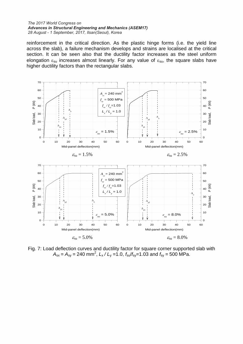
reinforcement in the critical direction. As the plastic hinge forms (i.e. the yield line across the slab), a failure mechanism develops and strains are localised at the critical section. It can be seen also that the ductility factor increases as the steel uniform
elongation su increases almost linearly. For any value of su, the square slabs have higher ductility factors than the rectangular slabs.
0 10 20 30 40 50 60
0
10
20
30
40
50
60
70
y1
Asx
= 240 mm2
fsy = 500 MPa
fsu
/ fsy=1.03
Lx / L
y = 1.0
su
= 1.5%
Sla
b lo
ad,
P (
kN)
Mid-panel deflection(mm)
u
0 10 20 30 40 50 60
0
10
20
30
40
50
60
70
su
= 2.5%
y2
y2
Sla
b lo
ad,
P (
kN)
Mid-panel deflection(mm)
y1
u
su = 1.5% su = 2.5%
0 10 20 30 40 50 60
0
10
20
30
40
50
60
70
Asx
= 240 mm2
fsy = 500 MPa
fsu
/ fsy=1.03
Lx / L
y = 1.0
su
= 5.0%
Sla
b lo
ad,
P (
kN)
Mid-panel deflection(mm)
y1
u
0 10 20 30 40 50 60
0
10
20
30
40
50
60
70
su
= 8.0%
y2
y2
Sla
b lo
ad,
P (
kN)
Mid-panel deflection(mm)
y1
u
su = 5.0% su = 8.0%
Fig. 7: Load deflection curves and ductility factor for square corner supported slab with
Asx = Asy = 240 mm2, Lx / Ly =1.0, fsu/fsy=1.03 and fsy = 500 MPa.

4.2 Edge-Supported Slabs
Square and rectangular two-way edge-supported slabs were numerically investigated with values of steel uniform elongation of 1.5, 2.5, 5.0 or 8.0% and stress ratio fsu/fsy = 1.03 and 1.05. The results of the parametric study for the edge-supported slabs is summarized in Table 4. Fig. 8 shows the detailed load deflection curves for the
case of a square slab with fsu/fsy = 1.03, Asx=Asy = 200 mm2, and fsy = 500MPa at su = 1.5, 2.5, 5.0 and 8.0%. The deflections Δy and Δu in the figures correspond to the mid-panel deflection when the first reinforcing wire yields and at ultimate load, respectively.
Table 4 lists the yield and peak loads and their associated deflections, load deflection ratios, absorbed work W0 and W1, and the ductility factors W1/W0. The Ly/Δ ratios are calculated based on the shorter span of the slabs (i.e. 2,200 mm for square and 1600 mm for rectangular slabs). Table 4 shows that square slabs are a little more ductile than the rectangular slabs and that the ductility factor increases as the steel uniform elongation increases. It is also noted that ductility of the edge-supported slabs is significantly greater than the corner supported slabs. This is due to high available redundancy in edge-supported slabs. The high redundancy allows loads to transfer from highly stressed areas to less stressed areas, and hence utilises the reserve strength in these locations in both directions. When the steel in the short direction starts to yield and the flexural strength in that direction is exhausted, additional load can be carried by other load mechanisms including torsion in the slab and membrane action. This makes edge-supported slabs exhibit reasonably ductile behaviour even at low values of steel uniform elongation, with significant plastic deformation before the peak load is reached.
Table 4 shows also that the span to deflection ratio Ly/Δu decreases when increasing the steel stress ratio fsu/fsy which means that the deflection at peak load increases with increasing fsu/fsy. The table also shows that the slab ductility increases
when increasing steel uniform elongation su and stress ratio fsu/fsy.

Table 4: Yield and peak loads and their associated deflections and absorbed work for edge-supported slabs with Asx = Asy = 200 mm2, fsy = 500 MPa, and fsu / fsy = 1.03.
Lx / Ly fsu/fsy su (%)
Py (kN)
Δy (mm)
Ly/Δy Pu
(kN) Δu
(mm) Ly/Δy
W0 kN.mm
W1 kN.mm
W1/ W0
1.0
1.03
1.5
88.8 6.03 365
94.8 15.95 138 465 909 1.95
2.5 96.2 21.74 101 465 1,461 3.14
5.0 96.8 36.24 60.7 465 2,859 6.15
8.0 97.0 47.03 46.8 465 3,905 8.40
1.05
1.5
88.8 6.03 365
95.0 16.4 134 465 949 2.04
2.5 96.4 22.6 97.2 465 1,546 3.32
5.0 97.2 36.7 59.9 465 2,906 6.25
8.0 97.4 47.6 46.2 465 3,964 8.52
1.375 1.03
1.5
101.2 4.72 339
105.0 9.77 164 416 511 1.23
2.5 109.8 13.7 117 416 944 2.27
5.0 110.0 22.8 70.2 416 1,946 4.68
8.0 110.0 32.6 49.1 416 3,052 7.34
In the edge-supported slabs, the applied load started to plateau only after the formation of the plastic hinge (i.e. yield of all the wires across the slab width and the formation of a failure mechanism). For the corner-supported slabs, the point at first cracking corresponded to a noticeable kink in the load-deflection curve (i.e. a significant change in direction of the curve), similar to the behaviour of one-way slabs reported in Gilbert and Sakka (2010). However, for the edge-supported slabs, the change in direction of the load-deflection curve at first cracking was relatively small and the loss of stiffness at first cracking was not as significant.
The two different boundary conditions selected for the study represent very different degrees of redundancy. The corner-supported two-way slabs have the least redundancy. In these slabs, the bending moment at mid-span in each direction varies across the slab width, being greatest near the column lines. The reinforcement at the critical section therefore yields progressively across the slab width as the applied load approaches the peak load. Eventually, all the reinforcement across the weaker direction yields and a failure mechanism forms. The mode of failure of a corner-supported two-way slab panel is similar to that of a one-way slab. In the case of the edge-supported slabs, a significant part of the load is carried by torsion and in-plane actions, in addition to bending in both orthogonal directions. This creates many paths for the applied load to transfer to the continuously supported edges.

0 10 20 30 40 50 60
0
20
40
60
80
100
120
y
Asy
= 200 mm2
fsy = 500 MPa
fsu
/ fsy=1.03
Lx / L
y = 1.0
su
= 1.5%
Sla
b lo
ad,
P (
kN)
Mid-panel deflection(mm)
u
0 10 20 30 40 50 60
0
20
40
60
80
100
120
su
= 2.5%
Sla
b lo
ad,
P (
kN)
Mid-panel deflection(mm)
y
u
su = 1.5% su = 2.5%
0 10 20 30 40 50 60
0
20
40
60
80
100
120
Asy
= 200 mm2
fsy = 500 MPa
fsu
/ fsy=1.03
Lx / L
y = 1.0
su
= 5.0%
Sla
b lo
ad,
P (
kN)
Mid-panel deflection(mm)
y1
u
0 10 20 30 40 50 60
0
20
40
60
80
100
120
su
= 8.0%
Sla
b lo
ad,
P (
kN)
Mid-panel deflection(mm)
y
u
su = 5.0% su = 8.0%
Fig. 8: Load deflection curves and ductility factor for edge-supported slab with Asx = Asy = 200 mm2, Lx / Ly =1.0, fsu/fsy=1.03 and fsy = 500 MPa.
Fig. 9 shows the ductility ratio W1/W0 versus the uniform elongation, su for the data in Tables 4 and 5. The figure shows that edge-supported slabs are more ductile than corner-supported slabs. It shows also that the slope of the best-fit lines for the edge-supported slabs is higher than the slope of the lines of the corner-supported slabs. This means that the change in the uniform elongation affects the ductility of slabs with high redundancy more than the less redundant slabs. The figure shows also that as the slab aspect ratio Lx/Ly increases (i.e. redundancy decreases), the slab ductility decreases significantly. Furthermore, it can be seen that the slab ductility increases as the stress ratio increases. This can be seen for both edge-supported and corner-supported slabs.

Fig. 9: Ductility ratio (W1/W0) versus uniform elongation. 5. SUMMARY AND CONCLUSIONS
The main conclusions drawn are as follows: 1. The two-way corner supported slabs reinforced with low ductility (Class L)
welded wire fabric fail in a brittle mode by fracture of the tensile reinforcement and, generally, not by crushing of the compressive concrete.
2. The uniform elongation of the reinforcement (su) has a significant effect on the ductility of two-way reinforced concrete slabs. However, the effect of the reinforcement ductility is much more prominent in the slabs with high redundancy than those with less redundancy.
3. Corner-supported slabs behave in a similar manner to one-way slabs, regardless of the slab aspect ratio Lx/Ly.
4. The change in slab aspect ratio Lx/Ly affects the ductility of edge-supported slabs much more than the corner-supported slabs.
5. The ductility of the two-way slabs is increased as the stress ratio is increased. 6. The load deflection curves for the corner-supported square and rectangular two-
way slabs were unsatisfactorily brittle when su < 3.0% and < 4.0%, respectively. These slabs had little ability to undergo significant plastic deformation at or close to the peak load. In all cases, fracture of the steel occurred at deformations not much larger than the deformation at peak load.
0.00
1.00
2.00
3.00
4.00
5.00
6.00
7.00
8.00
9.00
0 2 4 6 8 10
Duct
ilit
y (
W1/W
0)
Uniform elongation, su (%)

7. The square panels of the corner-supported and edge-supported two-way slabs have higher ductility factors than the rectangular panels.
8. A change in the steel uniform elongation su has a higher impact on the ductility factor than a change in fsu/fsy.
9. Edge-supported slabs have reasonable ductile behaviour even at low values of
su. This is due to the high redundancy and load transfer by mechanisms other than bending.
6. ACKNOWLEDGEMENT
This study was funded by the Australian Research Council through an ARC
Discovery project (DP0558370) and an Australian Professional Fellowship awarded to the second author. The support of the Australian Research Council is gratefully acknowledged. REFERENCES ATENA. (2016). Version 5.4. Bazant, Z. P., and Oh, B. H. (1983). "Crack Band Theory for Fracture of Concrete."
Materials and Structures, RILEM, Vol. 16 pp. 155-177. Cervenka, V., Jendele, L., and Cervenka, J. (2016). ATENA Program Documentation -
Part 1: Theory. Prague. De Borst, R. (1986). "Non-linear analysis of frictional materials". Ph.D. Thesis. Delft
University of Technology. Foster, S. J. and Kilpatrick, A. E. (2008). “The use of low ductility welded wire mesh in
the design of suspended reinforced concrete slabs”. Australian Journal of Structural Engineering, 8(3): 237-248.
Gilbert, R. I., and Sakka, Z. I. (2009). "Effect of Support Settlement on the Strength and Ductility of Reinforced Concrete One-way Slabs containing Class L Reinforcement." Concrete 09, Advances and Trends in Structural Engineering, Mechanics and Computation.
Gilbert, R. I., and Sakka, Z. I. (2007). "Effect of Reinforcement Type on the Ductility of Suspended Reinforced Concrete Slabs." Journal of Structural Engineering, 133(6), pp. 834–843.
Gilbert, R. I. (2005). "Strain Localization and Ductility of Reinforced Concrete Slabs". ASEC 2005, Australian Structural Engineering Conference.
Gilbert, R. I., Sakka, Z. I., and Curry, M. (2007). "The ductility of suspended reinforced concrete slabs containing Class L welded wire fabric." 19th Australasian Conference on the Mechanics of Structures and Materials, ACMSM19, November 29, 2006 - December 1, Taylor & Francis - Balkema, Christchurch, New zealand, 3-12.
Gilbert, R. I., Sakka, Z. I., and Curry, M. (2006). "Moment Redistribution In Reinforced Concrete Slabs Containing Welded Wire Fabric." Proceedings, The Tenth East Asia-Pacific Conference on Structural Engineering and Construction (EASEC-10), pp 305-310.

Gilbert, R. I., and Smith, S. T. (2006). "Strain Localization and its Impact on the Ductility of Reinforced Concrete Slabs Containing Welded Wire Reinforcement." Journal of Advances in Structural Engineering, 9(1), pp. 117-127.
Gilbert, R. I., and Sakka, Z. I. (2010). "Strength and ductility of reinforced concrete slabs containing welded wire fabric and subjected to support settlement." Eng. Struct., 32(6), 1509-1521.
Goldsworthy, H., Siddique, U. and Gravina, R. (2009). "Support settlement and slabs reinforced with low-ductility steel". ACI Structural Journal, 106(6): 840-847.
Menetrey, P., and Willam, K. J. (1995). "Triaxial failure criterion for concrete and its generalization." ACI, Structural Journal, 92(3), 311-318.
Mohammadhassani, M., Suhatril, M., Shariati , M., and Ghanbari, F. (2013). "Ductility and strength assessment of HSC beams with varying of tensile reinforcement ratios." Structural Engineering and Mechanics, an Int'l Journal, 48(6), 833-848.
Sakka, Z. (2009). "Impact of Steel Ductility on the Structural Behavior and Strength of RC Slabs.
Sakka, Z. I., and Gilbert, R. I. (2008a). "Effect of Reinforcement Ductility on the Strength and Failure Modes of One-way Reinforced Concrete Slabs." Rep. No. UNICIV Report R-450, School of Civil and Environmental Engineering, The University of New South Wales, Sydney, Australia.
Sakka, Z. I., and Gilbert, R. I. (2008b). "Effect of Reinforcement Ductility on the Strength, Ductility and Failure Modes of Continuous One-way Concrete Slabs Subjected to Support Settlement - Part 1." Rep. No. UNICIV Report R-451, School of Civil and Environmental Engineering, The University of New South Wales, Sydney, Australia.
Sakka, Z. I., and Gilbert, R. I. (2008c). "Effect of Reinforcement Ductility on the Strength, Ductility and Failure Modes of Continuous One-way Concrete Slabs Subjected to Support Settlement – Part 2." Rep. No. UNICIV Report R-452, School of Civil and Environmental Engineering, The University of New South Wales, Sydney, Australia.
Standards Australia. (2009). Concrete Structures. AS 3600-09, Sydney, Australia. Tuladhar, R. and Lancini, B. J. (2014). "Ductility of concrete slabs reinforced with low-
ductility welded wire fabric and steel fibers". Structural Engineering Mechanics, 49(4): 449-461.Warner, R. F., Rangan, B. V., Hall, A. S., and Faulkes, K. A. (1998). Concrete Structures. Longman, Australia.
Wilkins, M. L. (1964). "Calculation of elastic-plastic flow, Methods of Computational Physics." Methods of Computational Physics, 3.