numerical derivation of constitutive models for unbonded ... · uniform pressure and uniform cyclic...
TRANSCRIPT

1 Lecturer, E-mail address: [email protected]
2 PhD Student, E-mail address: [email protected]
3 Reader, E-mail address: [email protected]
1
Numerical Derivation of Constitutive Models
for Unbonded Flexible Risers
G. Alfano1, A. Bahtui
2 and H. Bahai
3
School of Engineering and Design, Brunel University, London, UB8 3PH, UK
Abstract
In this paper a new constitutive model for flexible risers is proposed and a procedure
for the identification of the related input parameters is developed using a multi-scale
approach. The constitutive model is formulated in the framework of an Euler-
Bernoulli beam model, with the addition of suitable pressure terms to the generalized
stresses to account for the internal and external pressures, and therefore can be
efficiently used for large-scale analyses. The developed non-linear relationship
between generalized stresses and strains in the beam is based on the analogy between
frictional slipping between different layers of a flexible riser and frictional slipping
between micro-planes of a continuum medium in non-associative elasto-plasticity.
Hence, a linear elastic relationship is used for the initial response in which no-slip
occurs; an onset-slip function is introduced to define the ‘no-slip’ domain, i.e. the set
of generalized stresses for which no slip occurs; a non-associative rule with linear
kinematic hardening is used to model the full-slip phase. The results of several
numerical simulations for a riser of small-length, obtained with a very detailed (small-
scale) non-linear finite-element model, are used to identify the parameters of the
constitutive law, bridging in this way the small scale of the detailed finite-element
simulations with the large scale of the beam model. The effectiveness of the proposed
method is validated by the satisfactory agreement between the results of various
detailed finite-element simulations for a short riser, subject to internal and external
uniform pressure and uniform cyclic bending loading, with those given by the
proposed constitutive law.
Keywords: non-associative plasticity; frictional slipping; parameter identification;
finite-element simulations; unbonded flexible pipes.
1 Introduction
The continuous development of unbonded flexible risers is a core factor supporting
the evolution of the subsea oil industry to face the challenges associated with the
increasing demand for ultra deep-water applications. The main advantage of flexible
risers with respect to rigid steel risers is the much lower bending stiffness of the
former, leading to smaller radii of curvature with the same pressure capacity, due to
the complex make up of flexible risers (API, 2002), in turn resulting in increased
ability of undergoing large deformations under loads induced by the sea current,
vortex-induced-vibrations, the motion of the floating-vessel and during installation.
The above advantages derive from the complex make-up of flexible risers, which
consists of different layers, each one designed for a specific task. Main components
are the helical armor layers and a set of sealing and/or anti-wear polymer layers, while

2
additional components which are typically present include a metallic internal ‘carcass’
and a pressure armor layer (API, 2002).
One of the problems associated with the complex design of unbonded flexible risers is
the difficulty in the analysis. To capture the many important aspects of their structural
response, including the energy dissipation due to frictional slip between layers, the
hysteretic response and the fatigue damage, efficient and accurate tools are required.
Current methods are generally divided into two categories: analytical formulations
and finite-element models. The analytical models share many of the following
simplifying assumptions, which significantly limit the range of applicability of the
results: displacements and strains are small (Feret and Bournazel, 1987; Claydon,
1992; Harte and McNamara, 1993); some coupling terms in total stiffness matrix are
neglected (Lanteigne, 1986; Harte and McNamara, 1993); the conventional elastic
thin-walled theory can be assumed valid (McNamara and Harte, 1989; Claydon,
1992); tendons are restricted from rotating about their local helical axis (Claydon,
1992); strains and/or stresses across the layer thickness are constant (Claydon, 1992);
thicknesses of layers remain constant during deformation (Claydon, 1992); plane
sections remain plane (Harte and McNamara, 1993); ovalisation effects are neglected
(Harte and McNamara, 1993; Kraincanic and Kebadze, 2001); contact and/or
frictional effects are ignored (Witz and Tan, 1992a&b; Harte and McNamara, 1993;
McIver, 1995; Brack et al., 2005; Tan et al., 2005); no slip occurs between layers
(Zhang et al., 2003); tendons are constrained to slide only along their own axis
(Kraincanic and Kebadze, 2001); tendons respond only axially, (bending and torsional
stiffness neglected) (Claydon, 1992; Harte and McNamara, 1993; Kraincanic and
Kebadze, 2001); the interlayer contact pressure is constant (Feret and Bournazel,
1987; Kraincanic and Kebadze, 2001); the contribution of the plastic sheaths to the
strength and stiffness of the riser can be neglected (Feret and Bournazel, 1987;
McIver, 1995); layers remain constantly in contact (no bird-caging effect) (Feret and
Bournazel, 1987; McNamara and Harte, 1989; Claydon, 1992); the radial deformation
is the same for all layers (Claydon, 1992; Kraincanic and Kebadze, 2001; Bahtui et
al., 2008a); initial manufacturing residual stresses can be ignored (Brack et al., 2005).
Claydon et al. studied the assessment of service life of unbonded flexible pipes under
deterministic cyclic loading (Claydon, 1992). They took the interlayer contact
pressures into account and also considered stress recovery, slip between layers and
riser interlayer wear and fatigue. Kraincanic and Kebadze presented a non-linear
formulation which accounts for the variation of the bending stiffness of an unbonded
flexible riser due to frictional sliding between layers, as a function of curvature,
friction coefficient and interlayer pressures (Kraincanic and Kebadze, 2001).
McNamara and Harte developed a method for calculating the deformations, stresses
and pressures in layered flexible pipelines under three-dimensional loading
(McNamara and Harte, 1989). Their model was capable of estimating wear, slip,
rupture, collapse of the carcass, and tendon failure. Similar approaches are used in
other analytical works (Bahtui et al., 2008a; Bahtui et al., 2008b; McIver, 1995;
Harte, 1993; Witz, 1992a; Witz, 1992b; Serta and Brack, 1990; Out, 1989; Feret,
1986; Lanteigne, 1986).
Almost all the weaknesses of these analytical methods can be overcome using
detailed, three-dimensional finite-element (FE) analyses, as is shown in previous work
by the authors (Bahtui et al., 2008a), where the results of a FE simulation for a six-
layer pipe made of a carcass layer, three anti-wear isotropic polymer layers and two
steel helical armor layers well correlate with those of an analytical model derived as a
combination and an enhancement of the work presented by Kraincanic and Kebadze

3
(2001), McNamara and Harte (1989) and Lanteigne (1986) and demonstrate higher
accuracy and reliability, as well as a wider range of applicability. However, the
downside of this type of analysis is the high computational cost so that, to make the
analysis feasible, the riser model length is restricted to only few meters in the best
case scenario for which top-end computational facilities and a large solution time are
available.
Figure 1: six-layer unbonded flexible riser analyzed by Bahtui et al. (2008a).
The aim of this paper is to address the above issue by combining the accuracy of a
detailed FE model of a short part of riser, with the low computational cost of a 3D
Euler-Bernoulli beam element, in the framework of a novel, multi-scale approach
capable of addressing large scale problems. An ‘equivalent elasto-plastic’ constitutive
law for the beam cross-section is introduced to relate axial strain, torsion and bending
curvatures to the conjugate stress resultants. Such law models the small-scale
frictional slip occurring between the layers, when a combination of values of the
stress resultants and of the internal and external pressures overcome a given threshold,
at the macroscopic level of the cross section. To this end, an ‘equivalent yield
function’ is defined, which depends on the current values of the stress resultants, on a
set of internal history variables, but also on the values of the external and internal
pressures acting on or within the pipe. This last functional relationship simulates the
effect that the pressure values have on the inter-layer normal stress, which in turn
affects the inter-layer frictional sliding and the overall dissipation. The zero level set
of the yield function represents the boundary of a ‘no-slip domain’, that is the onset of
slipping.
In formulating this first model a linear kinematic hardening law has been employed.
For the case of monotonic loading, the assumptions of linear hardening and of linear
elastic behavior within the ‘no-slip domain’ result in a bilinear response, which can
provide sufficient approximation of the structural response in many cases of interest.
This simplified model entails that the single cross section of the riser can be either in a
state in which ‘no slip’ is found, or in a state in which ‘full slip’ occurs.
The bridging between the beam model, suitable for large-scale analyses of the entire
riser, and the small-scale detailed FE model relies on the identification of the
parameters of the beam model, which is achieved through a combination of
reasonable engineering assumptions and careful curve fitting, using the small-scale
detailed FE model as a virtual testing rig. It is worth observing that the numerical

4
data, on which the constitutive model is calibrated on, can also be directly originated
from experiments if such results are available. However accurate experimental testing
of flexible risers which correctly reproduces the in-service conditions is difficult and
very expensive, whereas the availability of a detailed FE model to minimize the
number of required experiments is very important, and its use within the proposed
multi-scale method capable of analyzing both short and long risers is expected to have
a significant impact on the feasibility, accuracy and economy of the overall design
and analysis of flexible pipes.
The paper is structured as follows. In Section 2 the constitutive law for the 3D beam
model is formulated. In Section 3, the detailed FE model, mainly based on earlier
work by the authors (2008a), is described. In Section 4 the key issue of the
identification of the parameters of the beam constitutive model is addressed. In
Section 5 numerical results are presented and discussed to validate the effectiveness
of the proposed method. Some conclusions are finally drawn in Section 6, where other
aspects to be investigated in future work are also discussed.
2 Formulation of the Constitutive Model
In this Section the constitutive law of a flexible riser for an Euler-Bernoulli 3D beam
model is formulated. It is assumed that locally the pipe develops along a straight line,
so that an infinitesimal element of pipe can be represented as in Figure 2. A local
right-handed Cartesian system is introduced with the origin and the x and y axes
located at the cross section and the z axis coincident with the centroid axis.
2.1 Generalized stresses and strains
The stress resultants, shown in Figure 2, are the axial force N, the torque T, and the
bending moments around axes x and y, denoted by Mx and My, respectively.
Figure 2: stress resultants.
In addition, the internal and external pressures need to be considered in the model.
Referring to the cross-sectional view of the riser in Figure 3, the average radial
strain r is given by
in
inr
t
tt (1)
where tin and t denote the initial and the current thickness of the whole riser,
respectively. Notice that the negative sign is added for convenience in the above

5
equation so that the work done by the pressure parameter P , which is introduced
later in Equation (5), for a positive r is positive.
Figure 3: cross view of the riser section.
The radial displacement of the average radius, the radial displacement of the internal
layer and the radial displacement of the external layer, indicated with int,uur and extu ,
respectively, are related to the radial strain and to the current thickness as follows:
2
2int
tuu
tuu
rrext
rr
(2)
The work W done by the pressure per unit of length of the riser is then
extextext RuPRuPW 22 intintint (3)
where intR and extR are the internal and external radiuses, while intP and extP
represent the internal and external applied pressures.
By substituting Eq. 2 into Eq. 3 we have:
rru PuPW (4)
where uP and P are the conjugate actions working for ur and r , defined by:
)(
)(2
intint
intint
extext
extextu
RPRPtP
RPRPP
(5)
Increasing values of P result in increasing compression normal stresses between
layers in the radial direction and, therefore, in increasing frictional stresses. Instead,
the value of uP controls the radial displacement and does not affect the radial stresses
or the amount of friction.

6
Hence, in the proposed model uyxt PMMMN ,,,, and P are the generalized
stresses. The corresponding work-conjugated generalized strains
are rryxz u ,,,,, , where yxz ,, and are the axial strain, the curvatures
about the x and y directions and the torsional curvature, which are in turn related to
the axial displacement uz and the torsional rotation by the following relationships:
.;;;2
2
2
2
dz
d
dz
ud
dz
ud
dz
du xy
yx
zz
(6)
A compact notation is conveniently introduced denoting by and the generalized
stresses and strains:
r
r
y
x
z
u
y
x
t
u
P
P
M
M
M
N
(7)
2.2 Constitutive law
As discussed in Section 1, the constitutive law for the beam model is based on the
observation that the local (small-scale) frictional slip between the different layers
results in a macroscopic (large-scale) relationship between generalized stresses and
strains which has many analogies with the laws of elasto-plasticity.
Figure 4 shows the response of the flexible riser shown in Figure 1 under cyclic
loading, evaluated using a detailed three-dimensional FE analysis which accurately
models the interaction between all layers. For the qualitative analysis in this section,
presented to justify the assumptions of the proposed constitutive model, it is sufficient
to state that the values of the applied loading (internal and external pressures
included) are within a meaningful range typical of practical cases. For the first
monotonic increase of the curvature, the bending moment increases with an almost
linear stiffness between points (a) and (b). Then the stiffness rapidly decreases
between points (b) and (c) to a value which remains approximately constant up to
point (d). Upon unloading, the flexural stiffness is initially very close to the initial
stiffness, between points (d) and (e), and then it rapidly decreases between points (e)
and (f) to a value which is constant between points (f) and (g) and approximately
equal to that between points (c) and (d). Replacing the rounded parts between points
(b) and (c) and between points (e) and (f) with two sharp elbows, a bilinear curve
response is obtained with very good approximation. Such a bilinear curve represents
the same type of response as that obtained using an elasto-plastic model with linear
kinematic hardening, which is the model proposed here.

7
-20000
-15000
-10000
-5000
0
5000
10000
15000
20000
-0.1 -0.05 0 0.05 0.1
Curvature (1/m)
Ben
din
g M
om
en
t (N
.m)
a
b
c
d
e
f
g
Figure 4: plot of the bending moment against the corresponding
curvature for the unbonded flexible riser of Figure 1 during
cyclic loading; the response is evaluated with a detailed finite-
element simulation.
In analogy with the elasto-plastic case, the generalized strains are additively
decomposed into an elastic-like, i.e. ‘no-slip’, part e , and a plastic-like, i.e. ‘full-
slip’, part s .
se (8)
The generalized stress is obtained from the no-slip components of the generalized
strains via a linear-elastic relationship:
eD ˆ (9)
where D indicates the stiffness during the no-slip phase. The full-slip strains evolve
in accordance with a law which is analogous to the plastic flow rule of elasto-
plasticity, and which can be expressed as follows:
gs
, (10)
where g represents a suitable defined real-valued ‘slip potential’. The multiplier
evolves in accordance with the Khun-Tucker conditions:

8
0 0 f 0 f (11)
where represents the ‘back-stress’ associated with kinematic hardening.
The real-valued function f represents the equivalent of the yield function in elasto-
plasticity and will be indicated as ‘slip-onset’ function in view of its mechanical
meaning in the current context. When the stress resultant is such that
0 f , then no slip occurs, i.e. the stress resultants are inside the ‘no-slip’
domain. Instead, when 0 f , slip can occur because it is possible to have
0 .
Notice that it is not possible to have 0 f . However, the back-stress follows
the evolution of the full-slip component s in accordance with a hardening
relationship which, in this case, is assumed to be linear:
sH ˆ (12)
where H is a matrix of hardening coefficients. Therefore, although the value of the
slip-onset function remains constantly null during the frictional slipping phase, the
value of the stress components increase because of the hardening, in accordance with
the expected response shown in Figure 4.
The slip-onset function f and the potential g have to incorporate the dependence of the
response of the flexible pipe cross section on the current state of internal stress. In
particular, the values of the pressure component P has a great influence on the
normal interaction between layers and then on the onset of friction.
Notice that the slip potential g and the slip-onset function f are different because of the
frictional nature of the constitutive law. The mechanical meaning of this assumption
will be discussed later in more detail.
2.2.1 Finite-step equations
From a computational point of view, the time domain needs to be subdivided into a
number of finite steps. Adopting a fully implicit backward-Euler time-integration
scheme, the equations to solve in each step are as follows:
000
ˆ
0
ff
H
g
D
s
ss
s
(13)
In a conventional displacement-based finite-element analysis the constitutive law is
‘strain driven’, whereby the generalized strain at the end of the step and the history
variables at the beginning the step, that is 0s in this case, are given, and the
remaining variables at the end of the step, that is the stress , the back-stress and
the full-slip generalized strain s have to be computed. The solution is found

9
iteratively, using the same well-established return-map algorithms used in elasto-
plasticity.
The above equations provide a general formulation which is the basis for the current
and future developments of this research work. As will be discussed later in more
detail, the main difficulty lies in the identification of the coefficients of the stiffness
and hardening matrices D and H , and of both the expression and the related
coefficients of functions f and g. Addressing the most general case is not convenient
in this phase of the research work in which the main aim is to demonstrate the validity
and the potential of the proposed method. Hence, in the following section some
reasonable assumptions will be made to study some cases of significant interest.
2.2.2 Specialisation to the case of cyclic flexural loading
In this section, the very important case of cyclic flexural loading will be considered.
To simplify the treatment and better focus on the factors which have a major influence
on the structural response, the assumption is made that the axial force N and the
torque Mt are constant throughout the deformation process. Hence, their influence on
the determination of functions f and g can be incorporated within the coefficients and
then ignored. Furthermore, a pure elastic relationship can be assumed between N and
Mt and the conjugated variables z and , so that the hypothesis made that N and Mt
are constant allows us to completely ignore these terms.
A further simplifying assumption made is that 0uP . This seems reasonable in this
phase of the work because the main influence on the response of the flexible pipe on
the onset of and during frictional slipping is given by the other term P . The latter
simplification further reduces the number of degrees of freedom of the model and,
because of Eq. (5)1, it results in the following relationship to be satisfied by the
pressure values applied to the (small-scale) detailed FE model:
extext RPRP intint (14)
Symmetry of the cross section rules out coupling terms in the elastic relationship
between the remaining components of the generalized stresses and strains, and also
results in the same flexural response about the x and y axes, whereby the initial
stiffness is represented by a diagonal matrix:
r
y
x
y
x
D
D
D
P
M
M
33
11
11
00
00
00
(15)
The components of the back-stress vector which correspond to the generalised-
stress components xM , yM and P are denoted by x , y and , so that the
argument of the onset-slip function is given by:
P
M
M
yy
xx
(16)

10
To determine functions f and g and the coefficients of the kinematic hardening matrix,
many results of several numerical simulations made with the detailed FE model have
been reviewed and the following expression has been found to be sufficiently valid:
aPMMbf yyxx )(22
(17)
where a and b are material parameters to be identified, and again symmetry of the
cross section has been exploited.
The slip potential g has to account for the finding that frictional slipping in bending is
not accompanied by any significant relative opening between layers. At the small-
scale level this means that no significant dilatancy is observed in the frictional
slipping between layers. A suitable expression for the potential g which meets this
requirement is as follows:
22yyxx MMbg (18)
which results in the following slip rule:
0
2
2
y
x
y
x
sr
sy
sx
s Mb
Mb
P
g
M
g
M
g
g
(19)
where sysx , and sr denote the full-slip components of the bending curvatures
about the x and y axes and of the radial strain. Overlapping the generalized stresses
and strains spaces, Figure 5 describes the above equation and shows that the
inequality between functions f and g results in the full-slip strain rate s being not
normal to the slip-onset surface, i.e. not parallel to the normal n . This is in analogy
with the non-associative plasticity models used for many materials exhibiting internal
friction for which the normality rule is not satisfied.

11
Figure 5: non-associative behaviour of the proposed model.
The following proportional hardening law is used:
sr
sy
sx
y
x
ss hhH
ˆ (20)
It is worth observing that because of the slip law in Equation (19), the radial full-slip
strain sr results to be constantly zero, so that also does so and the above
equation further specializes as follows:
0
sy
sx
y
x
h
h
(21)
A final remark is that, having the same response about the x and y axes because of
symmetry, a simple plane model can be used to study the structural response and to
identify the model parameters, as will be done in Sections 3 to 5. Nevertheless, it was
preferred to derive all the above equations for the general case in which components
of moment and curvature about both axes are non-zero to clarify that the model can be
used in a general three-dimensional problem.
3 Detailed FE Model of an Unbonded Flexible Riser
Several FE simulations for a typical 1.7 m long unbonded flexible riser have been
conducted using the FE code ABAQUS. The model includes a complex make up of
seven-layers of internal and external plastic sheaths, helical armors, carcass and anti-
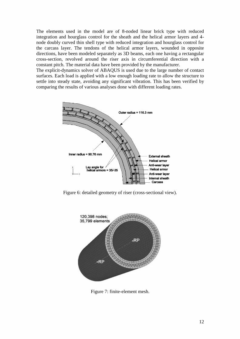
wear layers and is described in the cross-sectional view of Figure 6. It has been
created adding one additional layer to the model considered by the authors in previous
work (Bahtui et al., 2008a and 2008b). Figure 7 shows the finite element mesh of the
riser and indicates the number of nodes and elements used.
n
P
g
M
12
The elements used in the model are of 8-noded linear brick type with reduced
integration and hourglass control for the sheath and the helical armor layers and 4-
node doubly curved thin shell type with reduced integration and hourglass control for
the carcass layer. The tendons of the helical armor layers, wounded in opposite
directions, have been modeled separately as 3D beams, each one having a rectangular
cross-section, revolved around the riser axis in circumferential direction with a
constant pitch. The material data have been provided by the manufacturer.
The explicit-dynamics solver of ABAQUS is used due to the large number of contact
surfaces. Each load is applied with a low enough loading rate to allow the structure to
settle into steady state, avoiding any significant vibration. This has been verified by
comparing the results of various analyses done with different loading rates.
Figure 6: detailed geometry of riser (cross-sectional view).
Figure 7: finite-element mesh.

13
3D contact interaction is introduced between all layers, using a penalty contact
method based on Coulomb friction model together with the general contact algorithm
of ABAQUS/Explicit (Bahtui et al. 2008a), so that frictional sliding between the
layers is correctly accounted for. The friction coefficient is assumed to be 0.1, in
accordance with the experimental results provided by Saevik and Berge (1995).
For the identification of the parameters, it was enough to consider the planar case in
which moments are applied about the x axis in Figure 6. Accordingly, the only non-
zero flexural curvature is also about the same axis.
The analysis starts with an initial ‘pressure load step’ which accounts for the internal
fluid pressure and the external hydrostatic pressure. Four different input pressures are
analysed and referred to as cases 1, 2, 3, and 4, respectively. The values of the applied
internal and external pressures are given in Table 1 and satisfy Equation (14).
The pressure step is then followed by a ‘bending step’, in which a 16 kNm bending
moment is cyclically applied to the free end of the pipe. In each loading or unloading
part of the cycles the moment is applied linearly with time.
All the nodes at each of the two cross sections at both ends of the riser are rigidly
connected to two reference points which are positioned at the center of the sections
and marked as RP in Figure 7. The reference point connected to the bottom end of the
riser is completely constrained in all translational and rotational directions during the
analysis. The reference point which is connected to the top end of the riser model is
completely free during the pressure loading step, whereas for the bending step is fixed
in the rotational direction about the longitudinal axis of the riser.
Load
Case
Loads applied to riser
Pressure Loading
(MPa) P ( kN) Max. bending
moment (kNm)
Min. bending
moment (kNm)
1 Internal = 0
External = 0 0 16 -16
2 Internal = 10
External = 7.804 145.6 16 -16
3 Internal = 30
External = 23.41 436.9 16 -16
4 Internal = 50
External = 39.02 728.2 16 -16
Table 1: load cases – steps and magnitudes.
For each case analyzed, an average curvature of the riser has been computed at each
increment by dividing the rotation of the free end of the riser about the x axis by the
length of the riser. In Figure 8 the applied bending moment is plotted against the
computed average curvature for the four different load cases. Notice that the initial
pressure load step does not result in any curvature. As expected, results are similar to
those in Figure 4.
All results of Figure 8, except for the case P. = 0, illustrate a hysteretic behavior of
the riser subjected to cyclic bending moment, the response tending towards a
stabilized cyclic response gradually as the number of cycles increases. The first cycle
represents the installation phase, whereas the stabilized results are more suitable to be
used for the calibration procedure, which will be discussed in the next section. Figure
8 also shows that the higher the pressure, the more cycles are needed to reach a

14
stabilized hysteresis loop, and the greater the energy dissipated during the hysteresis
loop.
Case 1
Pε = 0
-20000
-15000
-10000
-5000
0
5000
10000
15000
20000
-0.15 -0.1 -0.05 0 0.05 0.1 0.15
Curvature (1/m)
Ben
din
g M
om
en
t (N
.m)
(a)
Case 2
Pε = 145.6 kN
-20000
-15000
-10000
-5000
0
5000
10000
15000
20000
-0.1 -0.05 0 0.05 0.1 0.15
Curvature (1/m)
Ben
din
g M
om
en
t (N
.m)
(b)

15
Case 3
Pε = 436.9 kN
-20000
-15000
-10000
-5000
0
5000
10000
15000
20000
-0.1 -0.05 0 0.05 0.1 0.15
Curvature (1/m)
Ben
din
g M
om
en
t (N
.m)
(c)
Case 4
Pε = 728.2 kN
-20000
-15000
-10000
-5000
0
5000
10000
15000
20000
-0.1 -0.05 0 0.05 0.1 0.15
Curvature (1/m)
Ben
din
g M
om
en
t (N
.m)
(d)
Figure 8: bending moment-curvature curves for the four different load cases (a)
P = 0, (b) P = 145.6 kN, (c) P = 436.9 kN and (d) P = 728.2 kN.
4 Calibration of the constitutive model
Several FE simulations have been used to calibrate the constitutive model. Each
bending moment-curvature result from the numerical simulations was curve fitted
using a bilinear curve, using the stabilised cycle. This bilinear curve can give three
specific parameters for the constitutive model: the initial no-slip slope, a slip-initiation
point, and a full-slip slope. In Figure 9 two representative results from the FE
simulations are shown together with the fitted bi-linear curves.

16
Pε = 291.3 kN
-20000
-15000
-10000
-5000
0
5000
10000
15000
20000
-0.1 -0.05 0 0.05 0.1
Curvature (1/m)
Be
nd
ing
Mo
me
nt
(Nm
)
(a)
Pε = 436.9 kN
-20000
-15000
-10000
-5000
0
5000
10000
15000
20000
-0.1 -0.05 0 0.05 0.1
Curvature (1/m)
Be
nd
ing
Mo
me
nt
(Nm
)
(b)
Figure 9: two representative results from the FE simulations and related fitted
bilinear curves.
For all cases except those with zero or very small applied pressure, an initial linear
response can very clearly be identified. Therefore, an initial ‘no-slip slope’ can be
determined and is found to be the same for each of the analysed cases. This validates
the hypothesis that an initial linear part of the moment-curvature diagram, in which
frictional slip between layers is absent or negligible, does exist. This slope directly
provides the flexural stiffness D11 = D22.
After this initial linear response, a non-linear part of the curve follows, which
relatively rapidly tends to join a final full-slip slope. Upon repeated loading and
unloading cycles, this final slope changes and stabilizes on a straight line which is that
used in the identification procedure. This final full-slip slope is not equal to the
hardening parameter h, but it is related to it and therefore its determination allows to
estimate h.

17
The intersection point between the initial slope and the final slope provides a ‘slip-
initiation’ point, which is also a point of the boundary of the no-slip domain, i.e. a
point of the zero level set of the slip-onset function.
Remark 4.1
In this proposed model, the non-linear transitional regime between the initial no-slip
response and the final full-slip response is replaced with a bilinear response and a
sharp elbow at the slip-initiation point. During the transition phase one part of the
layers in contact (particularly the armor tendons) slip with respect to each other, and
another part of them do not. Although the results of the proposed simplified model
can be accurate enough in many cases, it is important to underline that the method can
be further refined, as discussed later.
The slip-initiation points identified have been fitted with the quadratic expression of
Equation (17) and the resulting curve is shown in Figure 10.
0
100
200
300
400
500
600
700
0 1000 2000 3000 4000 5000 6000
Bending Moment (Nm)
Avera
ge P
ressu
re P
ε (k
N)
Figure 10: curve-fitting of the slip-initiation points.
Finally, the last parameter of the model to be identified is the stiffness value D33. This
has been done by analysing the pressure steps in the above described analyses for
different values of the pressure, and identifying the initial no-slip, nearly linear
response. Table 2 reports the parameters of the model determined with the proposed
procedure:
Stiffness Slip-onset function Hardening
D11 (kNm2) D33 (kN) a b (N
-1 m
-2) h (Nm
2)
608 26707 0 0.023 2.5 · 105
Table 2: identified parameters.
18
5 Validation of the model
To demonstrate the validity of the proposed method, the same cyclic analyses
performed using the detailed finite-element model in ABAQUS have been reproduced
using the simplified proposed constitutive model adopting the parameters of Table 2
identified as described in the previous section, and using the solution scheme
described in Section 2.1.
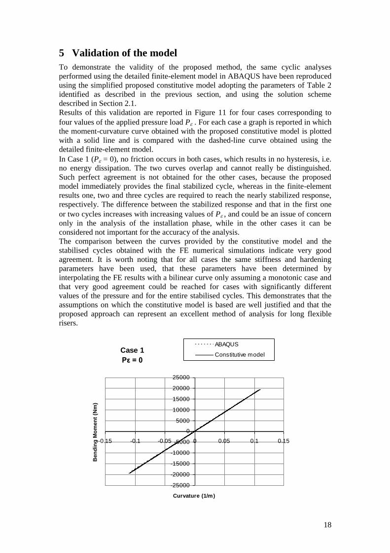
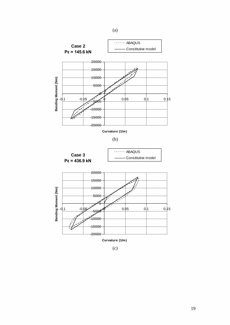
Results of this validation are reported in Figure 11 for four cases corresponding to
four values of the applied pressure load P . For each case a graph is reported in which
the moment-curvature curve obtained with the proposed constitutive model is plotted
with a solid line and is compared with the dashed-line curve obtained using the
detailed finite-element model.
In Case 1 (P = 0), no friction occurs in both cases, which results in no hysteresis, i.e.
no energy dissipation. The two curves overlap and cannot really be distinguished.
Such perfect agreement is not obtained for the other cases, because the proposed
model immediately provides the final stabilized cycle, whereas in the finite-element
results one, two and three cycles are required to reach the nearly stabilized response,
respectively. The difference between the stabilized response and that in the first one
or two cycles increases with increasing values of P, and could be an issue of concern
only in the analysis of the installation phase, while in the other cases it can be
considered not important for the accuracy of the analysis.
The comparison between the curves provided by the constitutive model and the
stabilised cycles obtained with the FE numerical simulations indicate very good
agreement. It is worth noting that for all cases the same stiffness and hardening
parameters have been used, that these parameters have been determined by
interpolating the FE results with a bilinear curve only assuming a monotonic case and
that very good agreement could be reached for cases with significantly different
values of the pressure and for the entire stabilised cycles. This demonstrates that the
assumptions on which the constitutive model is based are well justified and that the
proposed approach can represent an excellent method of analysis for long flexible
risers.
Case 1
Pε = 0
-25000
-20000
-15000
-10000
-5000
0
5000
10000
15000
20000
25000
-0.15 -0.1 -0.05 0 0.05 0.1 0.15
Curvature (1/m)
Ben
din
g M
om
en
t (N
m)
ABAQUS
Constitutive model
19
(a)
Case 2
Pε = 145.6 kN
-20000
-15000
-10000
-5000
0
5000
10000
15000
20000
-0.1 -0.05 0 0.05 0.1 0.15
Curvature (1/m)
Ben
din
g M
om
en
t (N
m)
ABAQUS
Constitutive model
(b)
Case 3
Pε = 436.9 kN
-20000
-15000
-10000
-5000
0
5000
10000
15000
20000
-0.1 -0.05 0 0.05 0.1 0.15
Curvature (1/m)
Ben
din
g M
om
en
t (N
m)
ABAQUS
Constitutive model
(c)

20
Case 4
Pε = 728.2 kN
-20000
-15000
-10000
-5000
0
5000
10000
15000
20000
-0.1 -0.05 0 0.05 0.1 0.15
Curvature (1/m)
Ben
din
g M
om
en
t (N
m)
ABAQUS
Constitutive model
(d)
Figure 11: comparison of the results obtained from the constitutive model (solid
line) and from the detailed FE model (dashed line).
6 Conclusions
A new method has been proposed for the formulation of constitutive models for
flexible risers, suitable for large-scale analyses, and for the identification of the
related input parameters. The approach used is multi-scale and entirely numerical. At
the small scale, a detailed finite-element model of a riser of small-length has been
used to conduct several numerical simulations for different values of the applied loads
and internal/external pressure. This model accurately takes into account the detailed
geometry of the riser and the frictional contact between various layers. At the large
scale, an Euler-Bernoulli beam model has been developed with the addition of
suitable pressure terms in the generalized stresses to account for the internal and
external pressures. The constitutive law for the beam model has been derived based
on a set of assumptions which are motivated by the analogy between the structural
response obtained in the numerical simulations and that of an elasto-plastic model
with non-associative type of flow rule, the frictional slipping between the different
layers of the riser producing a similar type of response as the frictional slipping of
micro-planes in a continuum medium. The parameters of the beam constitutive law
are identified by ensuring that the analyses performed at different scales provide as
close as possible results for a number of representative cases.
The beam model supplemented with the proposed constitutive law is clearly suitable
for large-scale analysis, unlike the detailed finite element model used to formulate it
and to determine its parameters. On the other hand, it is able to capture all the
important aspects of the structural response of the riser.
The model has been specialized to the important case of cyclic bending loading of a
riser subject to different values of internal and external pressures. In these first

21
developments of the method, linear kinematic hardening has been assumed. Very
good agreement has been obtained between the response provided by the proposed
(large-scale) model and that of the detailed (small-scale) finite element simulations.
This makes this first implemented model already suitable to study many problems,
such as hysteretic damping in vibration analysis.
In future work the constitutive law will be improved by including non-linear
hardening as well as more refined hardening models capable of simulating the
stabilisation of the response during cyclic loading. Further improvements can be made
by accounting for the presence of the shear force (switching to a Timoshenko beam
model) and by incorporating the influence of variable axial force and torque on the
non-linear response. Clearly, more sophisticated models will also imply more
parameters to be identified and therefore call on the development of more refined
identification procedures.
Acknowledgments
The work has been sponsored by Lloyds Register EMEA, which is gratefully
acknowledged for funding the project and for providing material properties and
geometrical data of the flexible pipe. In particular, the authors wish to thank Dr
Graham Stewart and Dr Lakis Andronicou from Lloyds Register for the precious and
fruitful discussions.
References
API, American Petroleoum Institute (2002). Recommended Practice for Flexible Pipe.
API Recommended Practice 17B, 3rd
Ed.
Alfano, G., Rosati, L., Valoroso, N. (1999). A Tangent-secant Approach to Rate-
independent elastoplasticity: Formulations and Computational Issues. Computer
Methods in Applied Mechanics and Engineering; 179: 379-405.
Bahtui, A., Bahai, H., Alfano, G. (2008a). A Finite Element Analysis for Unbonded
Flexible Risers under Torsion. Journal of Offshore Mechanics and Arctic
Engineering. In press.
Bahtui, A., Bahai, H., Alfano, G. (2008b). Numerical and Analytical Modeling of
Unbonded Flexible Risers. Submitted to Journal of Offshore Mechanics and Arctic
Engineering.
Claydon, P., Cook, G., Brown, P.A., Chandwani, R. (1992). A Theoretical Approach
to Prediction of Service Life of Unbonded Flexible Pipes under Dynamic Loading
Conditions. Marine Structures; 5(5): 399-429.
Crisfield, M.A. (1991). Non-linear Finite Element Analysis of Solids and Structures.
Volume 1. Chichester: John Wiley & Sons LTd.
Feret, J.J., Bournazel, C.L. (1987). Calculation of Stresses and Slip in Structural
Layers of Unbonded Flexible Pipes. Journal of Offshore Mechanics and Arctic
Engineering; 109: 263-269.

22
Feret, J.J., Bournazel, C.L., and Rigaud, J. (1986). Evaluation of Flexible Pipes' Life
Expectancy Under Dynamic Conditions. Offshore Technology Conference (OTC);
Houston, Texas, May, 83-90.
Harte, A.M., and McNamara, J.F. (1993). Modeling Procedures for the Stress
Analysis of Flexible Pipe Cross Sections. Transactions of the ASME; 115: 46-51.
Hill, R. (1950). The Mathematical Theory of Plasticity. Oxford: Oxford University
Press.
Kraincanic, I., Kebadze, E. (2001). Slip Initiation and Progression in Helical
Armouring Layers of Unbonded Flexible Pipes and its Effect on Pipe Bending
Behaviour. Journal of Strain Analysis; 36(3): 265-275.
Lanteigne, J. (1986). Theoretical Estimation of the Response of Helically Armored
Cables to Tension, Torsion, and Bending. Journal of Applied Mechanics-Transactions
of the ASME; 52: 423-432
McIver, D.B. (1995). A Method of Modelling the detailed Component and Overall
Structural Behaviour of Flexible Pipe Sections. Engineering Structures; 17(4): 254-
266.
McNamara, J.F., Harte, A.M. (1989). Three Dimensional Analytical Simulation of
Flexible Pipe Wall Structure. In Proceedings of the 8th International Conference on
Offshore Mechanics and Arctic Engineering; 1(8): 477-482.
Out, J.M.M. (1989). On the Prediction of the Endurance Strength of Flexible Pipe.
Offshore Technology Conference (OTC), Houston, Texas, May; 487-496.
Serta, O.B., and Brack, M. (1990). Stress and Strain Assessment of Multi-layer
Flexible Pipes. Proceedings of the First European Offshore Mechanics Symposium,
Trondheim, Norway, August; 442-448.
Witz, J.A., and Tan, Z. (1992a). On the Axial-Torsional Structural Behaviour of
Flexible Pipes, Umbilicals and Marine Cables. Marine Structures; 5: 205-227.
Witz, J.A., and Tan, Z. (1992b). On the Flexural Structural Behaviour of Flexible
Pipes, Umbilicals and Marine Cables. Marine Structures; 5: 229-249.