evaluation of composite pavement unbonded overlays
TRANSCRIPT

Evaluation of CompositePavement Unbonded Overlays:Phases I and II
Sponsored by
the Federal Highway Administration,U.S. Department of Transportation,Project DTFH6101X00042-CTRE Phases I and II, Project #2
and
the Iowa Department of Transportationand the Iowa Highway Research Board,Project HR-1093, TR-478
Construction ReportApril 2003
Department of Civil, Construction, and Environmental Engineering

The opinions, findings, and conclusions expressed in this publication are those of the authors andnot necessarily those of the U.S. Department of Transportation, Federal HighwayAdministration, Iowa Department of Transportation, or Iowa Highway Research Board. Thecontents of this report reflect the views of the authors, who are responsible for the facts and theaccuracy of the information presented herein. This document is disseminated under thesponsorship of the U.S. Department of Transportation, Federal Highway Administration, in theinterest of information exchange. The U.S. government assumes no liability for the contents oruse thereof. The sponsors do not endorse products or manufacturers. Trade and manufacturersnames appear in this report only because they are considered essential to the objective of thisdocument.
The mission of the Center for Portland Cement Concrete Pavement Technology (PCC Center) isto advance the state of the art of portland cement concrete pavement technology. The centerfocuses on improving design, materials science, construction, and maintenance in order toproduce a durable, cost-effective, sustainable pavement.
DISCLAIMER

Technical Report Documentation Page 1. Report No. 2. Government Accession No. 3. Recipient’s Catalog No. FHWA Project DRFH6101X00042-
CTRE Phases I and II, Project #2 Iowa DOT Project HR-1093, TR-478
4. Title and Subtitle 5. Report Date April 2003 6. Performing Organization Code
Evaluation of Composite Pavement Unbonded Overlays: Phases I and II
7. Author(s) 8. Performing Organization Report No. J.K. Cable, M.L. Anthony, F.S. Fanous, and B.M. Phares CTRE Project 01-95 9. Performing Organization Name and Address 10. Work Unit No. (TRAIS)
11. Contract or Grant No.
Center for Portland Cement Concrete Pavement Technology Iowa State University 2901 South Loop Drive, Suite 3100 Ames, IA 50011-8634
12. Sponsoring Organization Name and Address 13. Type of Report and Period Covered Construction Report 14. Sponsoring Agency Code
Federal Highway Administration U.S. Department of Transportation Washington, DC 20590 Iowa Highway Research Board Iowa Department of Transportation 800 Lincoln Way Ames, IA 50011
15. Supplementary Notes 16. Abstract In recent years, thin whitetopping has evolved as a viable rehabilitation technique for deteriorated asphalt cement concrete (ACC) pavements. Numerous projects have been constructed and tested; these projects allow researchers to identify the important elements contributing to the projects’ successes. These elements include surface preparation, overlay thickness, synthetic fiber reinforcement usage, joint spacing, and joint sealing. Although the main factors affecting thin whitetopping performance have been identified by previous research, questions still existed as to the optimum design incorporating these variables. The objective of this research is to investigate the interaction between these variables over time. Laboratory testing and field-testing were planned in order to accomplish the research objective. Laboratory testing involved shear testing of the bond between the portland cement concrete (PCC) overlay and the ACC surface. Field-testing involved falling weight deflectometer deflection responses, measurement of joint faulting and joint opening, and visual distress surveys on the 9.6-mile project. The project was located on Iowa Highway 13 extending north from the city of Manchester, Iowa, to Iowa Highway 3 in Delaware County. Variables investigated included ACC surface preparation, PCC thickness, synthetic fiber reinforcement usage, and joint spacing. This report documents the planning, equipment selection, construction, field changes, and construction concerns of the project built in 2002. The data from this research could be combined with historical data to develop a design specification for the construction of thin, unbonded overlays. 17. Key Words 18. Distribution Statement portland cement concrete pavement overlays, maturity, temperature-monitoring systems
No restrictions.
19. Security Classification (of this report)
20. Security Classification (of this page)
21. No. of Pages 22. Price
Unclassified. Unclassified. 28 + appendixes NA

EVALUATION OF COMPOSITE PAVEMENT UNBONDED OVERLAYS: PHASES I AND II
FHWA Project DTFH6101X0042-CTRE Phases I and II, Project #2 Iowa DOT Project HR-1093, TR-478
CTRE Project 01-95
Principal Investigator J.K. Cable
Associate Professor of Civil Engineering, Iowa State University
Co-Principal Investigators
F.S. Fanous Professor of Civil Engineering, Iowa State University
B.M. Phares
Manager, Bridge Engineering Center, Iowa State University Associate Director for Bridges and Structures, Center for Transportation Research and Education
Research Assistant
M.L. Anthony
Authors J.K. Cable, M.L. Anthony, F.S. Fanous, and B.M. Phares
Preparation of this report was financed in part through funds provided by the Iowa Department of Transportation
through its research management agreement with the Center for Transportation Research and Education.
Center for Portland Cement Concrete Pavement Technology Iowa State University
2901 South Loop Drive, Suite 3100 Ames, IA 50010-8634
Phone 515-294-8103; Fax 515-294-0467 www.ctre.iastate.edu/pcc/
Construction Report • April 2003

iii
TABLE OF CONTENTS
ACKNOWLEDGEMENTS........................................................................................................... ix
INTRODUCTION ...........................................................................................................................1
Background................................................................................................................................1 Research Objectives...................................................................................................................1
REVIEW OF CONCRETE OVERLAY PROJECTS......................................................................2
Ultrathin Whitetopping Experiences..........................................................................................2 Unbonded Overlay Experience on County Roads .....................................................................3
TEST SITE DESCRIPTION............................................................................................................4
Soil Conditions...........................................................................................................................7 Design Traffic ............................................................................................................................8
EXPERIMENTAL DESIGN ...........................................................................................................9
CONSTRUCTION.........................................................................................................................14
Construction Concerns.............................................................................................................21 Field Changes...........................................................................................................................23
TEST FREQUENCY AND METHODS.......................................................................................25
Lab Shear Testing ....................................................................................................................25 Field Testing ............................................................................................................................26
Falling Weight Deflectometer Testing...............................................................................26 Joint Openings and Faulting Measurements ......................................................................26 Visual Distress Surveys .....................................................................................................27 Weigh-in-Motion Device Measurements...........................................................................27 Cross Sectional Structural Analysis...................................................................................27
SUMMARY...................................................................................................................................28
REFERENCES ..............................................................................................................................28
APPENDIX A: MATURITY MEASUREMENT EQUIPMENT EVALUATION ................... A-1
APPENDIX B: FALLING WEIGHT DEFLECTOMETER DATA...........................................B-1
APPENDIX C: JOINT OPENING AND FAULTING DATA....................................................C-1
APPENDIX D: CROSS SECTIONAL STRUCTURAL ANALYSIS....................................... D-1

v
LIST OF FIGURES Figure 1. Project Location............................................................................................................... 5 Figure 2. Pavement Layers and the Dates of Construction............................................................. 6 Figure 3. Longitudinal Cracking and Current Condition of the Roadway ..................................... 6 Figure 4. Typical Cross Section for the Iowa Highway 13 Project .............................................. 14 Figure 5. Scarified Pavement Surface........................................................................................... 15 Figure 6. Completed Milling Operation........................................................................................ 15 Figure 7. HMA Stress Relief Layer .............................................................................................. 16 Figure 8. Tied Transverse Crack................................................................................................... 17 Figure 9. Labeling Plate................................................................................................................ 18 Figure 10. Stapled #4 Bar that Ties the Widening Unit to the Thin Overlay ............................... 19 Figure 11. Longitudinal Joint Forming Knife............................................................................... 19 Figure 12. Typical of Panel Sizes ................................................................................................. 20 Figure 13. Fibers Being Blown into the Concrete Mixing Drum ................................................. 21 Figure 14. Adjustment to Blower for Better Fiber Dispersion ..................................................... 22 Figure 15. Schematic of FWD Deflection Sensors....................................................................... 26

vii
LIST OF TABLES Table 1. UTW Properties for the Louisville, Kentucky, Project .................................................... 2 Table 2. UTW Properties for the Leawood, Kansas, Project.......................................................... 2 Table 3. Soil Names and AASHTO Classifications of Project Soils.............................................. 7 Table 4. Design Characteristics of Current UTW Projects............................................................. 9 Table 5. Test Section Characteristics............................................................................................ 10 Table 6. Stationing and Side of the Road of New/Existing Longitudinal Subdrains ................... 16 Table 7. Tied Transverse Crack Locations ................................................................................... 17 Table 8. Adjusted Beginning and Ending Stations of Fiber Inclusion ......................................... 24 Table 9. Information and Results of Shear Test ........................................................................... 25

ix
ACKNOWLEDGEMENTS
The construction of this project would not have been possible without the cooperation of the Fred Carlson Company and the Iowa Department of Transportation Office of Materials, Office of Construction, and the Resident Engineers’ Staff—Manchester Office. Funding would not have been possible without the help of the Iowa Highway Research Board and the Federal Highway Administration. The Iowa Concrete Paving Association helped make the project a reality with their support of the concept. Special thanks goes out to Alan Johnson of W.R. Grace for supplying the blower, which dispersed the fibers more evenly, and for being on site to deal with any fiber-related problems that arose. This is another great example of how industry partnerships move technology forward.

1
INTRODUCTION
Background
Iowa is one of several states known for its large amounts of portland cement concrete (PCC) pavements. The original design life of the initial pavement systems was established as 20 years. This meant that by the 1970s much of the system had reached or was exceeding the design life. The decision was made to widen and resurface these pavements with asphalt cement concrete (ACC). This philosophy was used to extend the life for 10–15 years or until funding could be found to replace the pavements.
Rather than continue to overlay these composite pavements with asphalt, concrete alternatives that provide longer life at a lower life-cycle cost were needed. Thin, unbonded concrete overlays are a relatively new idea in the paving industry. Unbonded PCC overlays have been used to extend the pavement life of Iowa Highway 21 near Belle Plaine, Iowa. From this research, several valuable things were learned about slab thickness, bond strength, and the use of fiber reinforcement in the concrete. However, there is a definite need for further research in order to present a cost-effective concrete alternative to asphalt overlays.
Research Objectives
The goal of this research project was to measure the stability and durability of unbonded, thin PCC overlays over time. In conducting the research, the following factors were considered:
• bonding between the PCC and ACC layers • joint spacing • PCC thickness • use of concrete fibers in the concrete • surface preparation • joint/crack preparation in the existing pavement
The objectives of this research will be accomplished by conducting both laboratory and field tests, collecting data, and analyzing the data appropriately. Following these steps, a final report containing information regarding the various research components will be produced. The report will document practices and results, as well as information concerning the achievements of the research.

2
REVIEW OF CONCRETE OVERLAY PROJECTS
Ultrathin Whitetopping Experiences
In 1991, the first modern ultrathin whitetopping (UTW) project was constructed on an entrance road to a waste management facility near Louisville, Kentucky. The project focused on assessing the viability of UTW. Table 1 shows the UTW properties for the project.
Table 1. UTW Properties for the Louisville, Kentucky, Project
Section Number
Dimensions (feet x feet)
PCC Thickness(inches)
Surface Preparation
Synthetic Fiber Usage (lb./c.y.)
Joint Spacing(feet x feet)
1 275 x 24 3.5 Milled 3.0 6 x 6 2 50 x 24 3.5–2.0 Milled 3.0 6 x 6 3 275 x 24 2.0 Milled 3.0 6 x 6, 2 x 2 The first urban arterial UTW project was developed in 1995. The city of Leawood, Kansas, constructed it, in conjunction with the Kansas Department of Transportation. The roadway selected was 119th Street between Roe Avenue and Mission Road. The project focused on evaluating synthetic fiber reinforcement usage, joint spacing, joint sealing, and the suitability of UTW in an urban application. Table 2 shows the UTW properties for the project.
Table 2. UTW Properties for the Leawood, Kansas, Project
Section Number
Dimensions (feet x feet)
PCC Thickness (inches)
Surface Preparation
Synthetic Fiber Usage (lb./c.y.)
Joint Spacing (feet x feet)
Joint Sealant
1 800 x 24 2.0 Milled 3.0 3 x 3 — 2 800 x 24 2.0 Milled — 3 x 3 — 3 800 x 24 2.0 Milled 3.0 3 x 3 Silicone4 800 x 24 2.0 Milled — 4 x 4 — 5 800 x 24 2.0 Milled 3.0 4 x 4 — 6 800 x 24 2.0 Milled — 4 x 4 Silicone In 1994, the Iowa Department of Transportation (Iowa DOT) constructed a 7.2-mile UTW project in Iowa County, near Belle Plaine, Iowa. The project was located on Iowa Highway 21 between Iowa Highway 212 and U.S. Highway 6. The objective of this research was to investigate the interface bonding condition between an ultrathin PCC overlay and an ACC base over time with consideration for the ACC surface preparation (milled, patch only, or cold in-place recycle), PCC thickness (2, 4, 6, or 8, inches), synthetic fiber reinforcement usage (fibrillated, monofilament, or no fibers), joint spacing (2 x 2, 4 x 4, 6 x 6, 12 x 12, and 15 x 12 foot panels), and joint sealing (widths of 1/8 or 1/4 of an inch, seal or no seal).

3
The conclusions from these projects and the results of the Iowa Highway 13 will be used to formulate a design specification for UTW projects.
Unbonded Overlay Experience on County Roads
Pottawattamie County has been interested in the unbonded overlay of a composite pavement since the early 1990s. The county has constructed nine separate projects involving the overlay of composite pavements consisting of an original PCC pavement with a surface layer of various depths of bituminous materials.
The earliest unbonded overlay was placed on 9.44 miles in 1992. The original section was 22 feet in width and made up of a 6-inch depth of PCC layer with a 3-inch asphaltic concrete overlay. A 6-inch PCC overlay was placed on the composite pavement. The visual survey in 2002 identified some 61 transverse joint patches, and some 268 longitudinal cracks primarily at the lane midpoint or centerline.
In the same year, the county tried to use a slurry coat as the bond breaker between an existing 22-foot wide, 6-inch-deep PCC pavement and a 6-inch PCC overlay of three projects for a total length of 7.9 miles. Testing indicated that the slurry effort was not successful as a bond breaker. The 2002 visual survey identified some 26 transverse joint patches and over 50 longitudinal cracks of random or midlane location.
In 1995, the county constructed 10.57 miles of unbonded overlay on a 22-foot-wide PCC pavement, 6 inches in depth, overlaid by 3 inches of ACC. A 2002 visual survey of the project noted approximately 100 feet of longitudinal random cracks, two transverse cracks, and one corner crack.
Approximately 3.07 miles of unbonded overlay were placed on a 22-foot-wide section of PCC in 1996, which was 6 inches in depth and had a previous 3-inch ACC overlay placed at various locations in 1963–1976. A 6-inch PCC overlay was placed on this pavement. This pavement currently exhibits only minor evidence of transverse joint cracking and one expansion joint problem.
In 2000, the county overlaid 5.00 miles of 22-foot-wide pavement with 6 inches of PCC. The underlying 6-inch PCC pavement that was overlaid with 2 inches of ACC in previous years. This project points out the need to consider expansion joints in the design, with some 18 expansion joints noting some distress and one corner broken slab in the project.
In 2001, the county constructed two unbonded overlay projects. The first was 1.01 miles in length, 22 feet in width, and consisted of a thickened edge (7 inches) and centerline (6 inches) depth. It was overlaid in previous years with 4 inches of ACC. No distress is noted at this time in the overlay.

4
The second unbonded overlay placed in 2001 was 6.00 miles in length, 22 feet in width, and placed on 2 inches of ACC over 6 inches of original PCC. There are no signs of visual distress showing on this project also.
The lessons learned from the Pottawattamie County experience include the following:
• Slurry bond breakers are not sufficient in depth to develop the bond breaker impact on the overlay performance.
• Attention must be given to existing expansion joints or the evidence of soil movement areas in the design of the joint locations in the overlay.
• Bridging or reinforcement over existing working cracks should be considered in the overlay design.
• Unbonded PCC overlays can be placed efficiently over composite pavements and provide good performance for extending the life of in-service pavements.
TEST SITE DESCRIPTION
Existing pavement condition was a major factor in the site decision. Care was also taken to select a project that could be constructed during the summer months of June through August. These dates were used to reduce the effects road closure would have on the through traffic as well as the school traffic. It was also desirable to take advantage of the warm, summer temperatures to increase the speed of concrete strength development.
The Iowa Highway 13 project is a 9.6-mile long stretch of roadway that extends from Manchester, Iowa, to Iowa Highway 3 in Delaware County. Figure 1 illustrates the project location. This portion of Iowa 13 is a two-lane rural roadway, 24 feet in width, with a narrow granular surfaced shoulder and rolling longitudinal grade with minimum ditch depths approximately 3 to 6 feet below the top of the pavement.
In 1931, the first improvements were made to Iowa 13 in the project area. The improvements included a thickened edge pavement with 10-inch depths at each edge and 7 inches at the centerline, 18 feet wide centered on the roadbed. The pavement cross section also included a 4-inch high lip curb on each edge to control pavement drainage. Longitudinal subdrains were placed at the low points of the roadway to facilitate water runoff. Table 6 shows the stationing and side of the road of the existing subdrains. The concrete slab was used as the driving surface until 1964, when 2 inches of Type B ACC was placed over it. This was done in order to both fill in the curbed section on the outer wheel path and rehabilitate the driving surface. In 1984, another 3-inch ACC widening surface was applied to the roadway. The first lift was 1.5 inches of Type B ACC binder and the surface layer was 1.5 inches of Type A ACC. This overlay extended the roadway from its original 18 feet to its present 24-foot width. Figure 2 shows the pavement layers and the dates of their construction.

5
Figure 1. Project Location

6
Figure 2. Pavement Layers and the Dates of Construction
The roadway, in 2002, was in good to fair condition with minimum cracking. One longitudinal crack extended through the entire 9.6 miles of roadway. It was located on both sides of the road where the concrete slab ends and the asphalt-widening unit extends. Figure 3 shows the longitudinal crack and the current condition of some of the roadway. Prior to the placement of the concrete overlay, the “floating” asphalt section was milled down to be replaced with a full 8-inch PCC slab.
Figure 3. Longitudinal Cracking and Current Condition of the Roadway

7
Soil Conditions
According to the Iowa County Soil Survey Report, Clyde - Floyd Complex and Kenyon Loam are the primary soil associations that occur along the project. The Clyde - Floyd Complex is deposited in the drainage ways of glacial uplands. This association is generally poorly drained, the permeability is moderate, the runoff is slow, and the soil has a high water capacity. This is a poor road fill soil because of its low strength and wetness. The Kenyon Loam is deposited along ridge tops and side slopes in the uplands. This association is generally moderately well drained, the permeability is moderate, the runoff is medium, and the soil has a high water capacity. This is a fair roadfill soil because of is low strength. Table 3 details the soil names and American Association of State Highway and Transportation Officials (AASHTO) classifications of the project soils.
Table 3. Soil Names and AASHTO Classifications of Project Soils
Station to Station Soil Name and Class AASHTO Classification 5100 6300 Waspie Loam A-4 6300 6800 Saude Loam A-6 6800 7200 Lawler Loam A-6, A-7 7200 7500 Clyde - Floyd Complex Clyde A-7, Floyd A-6, A-7 7500 8000 Olin Fine Sandy Loam A-2, A-4 8000 8400 Clyde - Floyd Complex Clyde A-7, Floyd A-6, A-7 8400 9200 Kenyon Loam A-6 9200 9500 Clyde - Floyd Complex Clyde A-7, Floyd A-6, A-7 9500 9800 Kenyon Loam A-6 9800 10100 Clyde - Floyd Complex Clyde A-7, Floyd A-6, A-7
10100 11700 Kenyon Loam A-6 11700 12100 Clyde - Floyd Complex Clyde A-7, Floyd A-6, A-7 12100 15300 Kenyon Loam A-6 15300 16600 Clyde - Floyd Complex Clyde A-7, Floyd A-6, A-7 16600 17400 Kenyon Loam A-6 17400 17600 Clyde - Floyd Complex Clyde A-7, Floyd A-6, A-7 17600 18500 Kenyon Loam A-6 18500 19700 Clyde - Floyd Complex Clyde A-7, Floyd A-6, A-7 19700 19900 Kenyon Loam A-6 19900 20700 Clyde - Floyd Complex Clyde A-7, Floyd A-6, A-7 20700 21200 Kenyon Loam A-6 21200 21500 Dickinson Fine Sandy Loam A-4, A-2 21500 22000 Olin Fine Sandy Loam A-2, A-4 22000 22900 Clyde - Floyd Complex Clyde A-7, Floyd A-6, A-7 22900 23200 Rockton Loam A-4 23200 26200 Clyde - Floyd Complex Clyde A-7, Floyd A-6, A-7 26200 26700 Kenyon Loam A-6 26700 27100 Clyde - Floyd Complex Clyde A-7, Floyd A-6, A-7 27100 28000 Kenyon Loam A-6 28000 28300 Clyde - Floyd Complex Clyde A-7, Floyd A-6, A-7 28300 28700 Kenyon Loam A-6 28700 29900 Clyde - Floyd Complex Clyde A-7, Floyd A-6, A-7
8
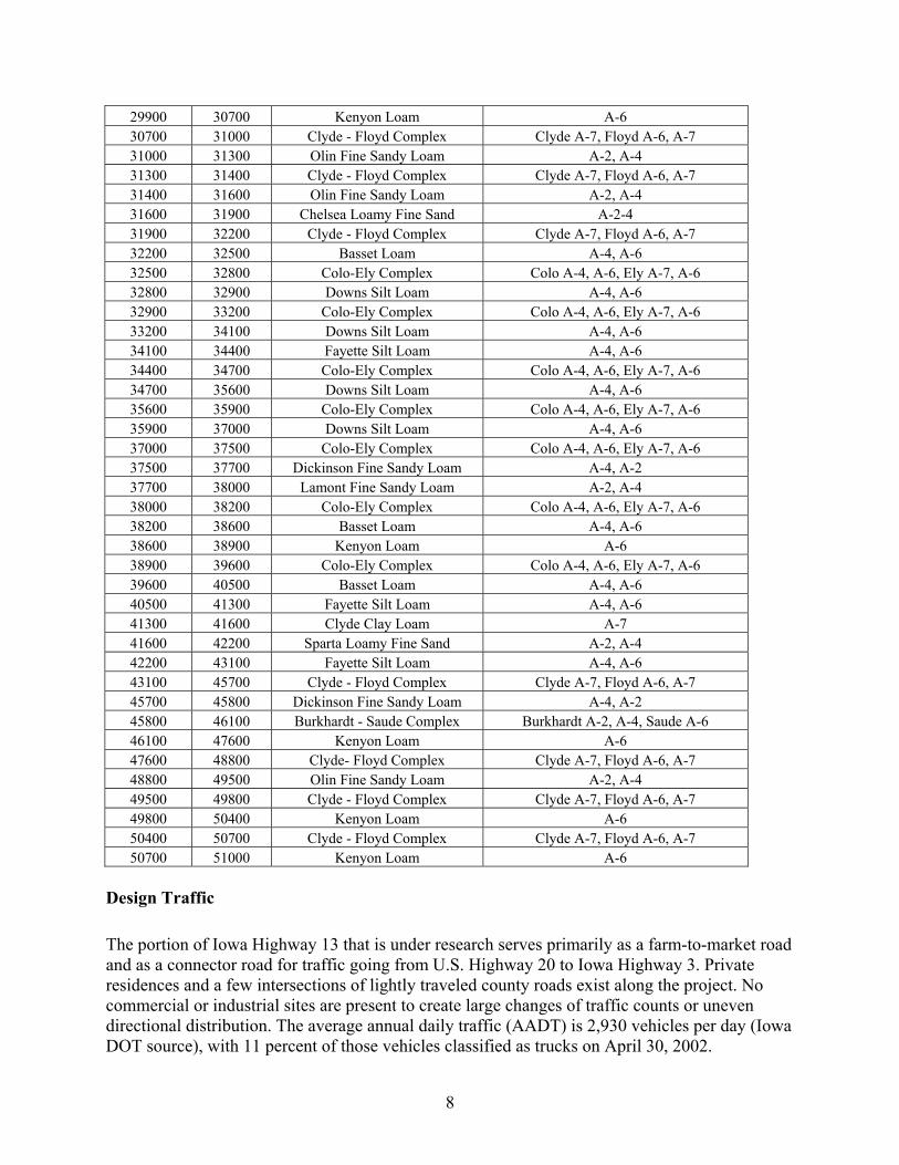
29900 30700 Kenyon Loam A-6 30700 31000 Clyde - Floyd Complex Clyde A-7, Floyd A-6, A-7 31000 31300 Olin Fine Sandy Loam A-2, A-4 31300 31400 Clyde - Floyd Complex Clyde A-7, Floyd A-6, A-7 31400 31600 Olin Fine Sandy Loam A-2, A-4 31600 31900 Chelsea Loamy Fine Sand A-2-4 31900 32200 Clyde - Floyd Complex Clyde A-7, Floyd A-6, A-7 32200 32500 Basset Loam A-4, A-6 32500 32800 Colo-Ely Complex Colo A-4, A-6, Ely A-7, A-6 32800 32900 Downs Silt Loam A-4, A-6 32900 33200 Colo-Ely Complex Colo A-4, A-6, Ely A-7, A-6 33200 34100 Downs Silt Loam A-4, A-6 34100 34400 Fayette Silt Loam A-4, A-6 34400 34700 Colo-Ely Complex Colo A-4, A-6, Ely A-7, A-6 34700 35600 Downs Silt Loam A-4, A-6 35600 35900 Colo-Ely Complex Colo A-4, A-6, Ely A-7, A-6 35900 37000 Downs Silt Loam A-4, A-6 37000 37500 Colo-Ely Complex Colo A-4, A-6, Ely A-7, A-6 37500 37700 Dickinson Fine Sandy Loam A-4, A-2 37700 38000 Lamont Fine Sandy Loam A-2, A-4 38000 38200 Colo-Ely Complex Colo A-4, A-6, Ely A-7, A-6 38200 38600 Basset Loam A-4, A-6 38600 38900 Kenyon Loam A-6 38900 39600 Colo-Ely Complex Colo A-4, A-6, Ely A-7, A-6 39600 40500 Basset Loam A-4, A-6 40500 41300 Fayette Silt Loam A-4, A-6 41300 41600 Clyde Clay Loam A-7 41600 42200 Sparta Loamy Fine Sand A-2, A-4 42200 43100 Fayette Silt Loam A-4, A-6 43100 45700 Clyde - Floyd Complex Clyde A-7, Floyd A-6, A-7 45700 45800 Dickinson Fine Sandy Loam A-4, A-2 45800 46100 Burkhardt - Saude Complex Burkhardt A-2, A-4, Saude A-6 46100 47600 Kenyon Loam A-6 47600 48800 Clyde- Floyd Complex Clyde A-7, Floyd A-6, A-7 48800 49500 Olin Fine Sandy Loam A-2, A-4 49500 49800 Clyde - Floyd Complex Clyde A-7, Floyd A-6, A-7 49800 50400 Kenyon Loam A-6 50400 50700 Clyde - Floyd Complex Clyde A-7, Floyd A-6, A-7 50700 51000 Kenyon Loam A-6
Design Traffic
The portion of Iowa Highway 13 that is under research serves primarily as a farm-to-market road and as a connector road for traffic going from U.S. Highway 20 to Iowa Highway 3. Private residences and a few intersections of lightly traveled county roads exist along the project. No commercial or industrial sites are present to create large changes of traffic counts or uneven directional distribution. The average annual daily traffic (AADT) is 2,930 vehicles per day (Iowa DOT source), with 11 percent of those vehicles classified as trucks on April 30, 2002.

9
EXPERIMENTAL DESIGN
After analyzing the performance of past UTW projects, Iowa Highway 13 has the advantage of testing the top performing design alternatives within one roadway. The design variables that were considered in this project include ACC surface preparation (milled, one-inch hot mix asphalt [HMA] stress relief course, and broomed only); use of concrete fibers (sections of polypropylene, monofilament, proprietary structural, and no fibers); pavement thickness (3.5 and 4.5 inches); joint spacing (4.5 x 4.5, 6 x 6, and 9 x 9 foot sections); and joint/crack preparation (bridge with concrete or a #4 rebar stapled to the pavement surface). Table 4 shows the design characteristics of this project and other UTW projects.
Table 4. Design Characteristics of Current UTW Projects Project Reference Design Characteristics A B C D
Location (date)
Entrance road to waste management facility, Louisville, Kentucky (1991)
Iowa Highway 21, between Victor and Belle Plaine, Iowa (1994)
119th Street, Leawood, Kansas (1995)
Iowa Highway 13, between Manchester, Iowa, and Iowa Highway 3 (2002)
Concrete thickness (inches) 2, 3.5 2, 4, 6, 8 2 3.5, 4.5
Joint spacing (feet) 2, 6 squares 2, 4, 6, 12 squares 3, 4 squares 4.5, 6, 9 squares
Asphalt treatment Milled Patch and scarify, patch only, cold in-place recycle
Milled Milled, HMA stress relief layer, broomed only
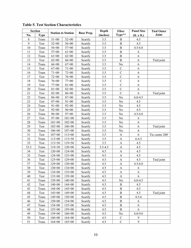
Fibers Yes Some Some Some The project was divided into 183 sections according to the previously mentioned variables, including 91 test sections. The test sections had lengths of 400 feet except for four that had to be increased to 600 feet to accommodate changes to the project beginning and the end. Each of the test sections represents a stretch of roadway where all of the variables remained constant. The change of a variable was accomplished in the transition sections, which precede each of the test sections. Table 5 displays the design properties for the project test sections.
10
Table 5. Test Section Characteristics Section Depth Panel Size
No. Type Station to Station Base Prep.
(inches) Fiber
Type** (ft. x ft.) Tied Outer
Joint 8 Trans 51+00 52+00 Scarify 3.5 B 4.5 9 Test 52+00 56+00 Scarify 3.5 B 4.5
10 Trans 56+00 57+00 Scarify 3.5 B 4.5-6.0 11 Test 57+00 61+00 Scarify 3.5 B 6 12 Trans 61+00 62+00 Scarify 3.5 B 6 13 Test 62+00 66+00 Scarify 3.5 B 6 Tied joint 14 Trans 66+00 67+00 Scarify 3.5 No 6 15 Test 67+00 71+00 Scarify 3.5 C 6 16 Trans 71+00 72+00 Scarify 3.5 C 6 17 Test 72+00 76+00 Scarify 3.5 C 6 18 Trans 76+00 77+00 Scarify 3.5 C 6 19 Test 77+00 81+00 Scarify 3.5 C 6 20 Trans 81+00 82+00 Scarify 3.5 C 6 21 Test 82+00 86+00 Scarify 3.5 C 6 Tied joint 22 Trans 86+00 87+00 Scarify 3.5 No 6.0-4.5 23 Test 87+00 91+00 Scarify 3.5 No 4.5 24 Trans 91+00 92+00 Scarify 3.5 No 4.5 25 Test 92+00 96+00 Scarify 3.5 No 4.5 26 Trans 96+00 97+00 Scarify 3.5 No 4.5-6.0 27 Test 97+00 101+00 Scarify 3.5 No 6 28 Trans 101+00 102+00 Scarify 3.5 No 6 29 Test 102+00 106+00 Scarify 3.5 No 6 Tied joint 30 Trans 106+00 107+00 Scarify 3.5 No 6 31 Test 107+00 113+00 Scarify 3.5 A 6 Tie center 200' 32 Trans 113+00 113+50 Scarify 3.5 A 6-4.5 33 Test 113+50 119+50 Scarify 3.5 A 4.5
33.5 Trans 119+50 120+00 Scarify 3.5-4.5 A 4.5 34 Test 120+00 124+00 Scarify 4.5 A 4.5 35 Trans 124+00 125+00 Scarify 4.5 A 4.5 36 Test 125+00 129+00 Scarify 4.5 A 4.5 Tied joint 37 Trans 129+00 130+00 Scarify 4.5 A 4.5-6.0 38 Test 130+00 134+00 Scarify 4.5 A 6 39 Trans 134+00 135+00 Scarify 4.5 A 6 40 Test 135+00 139+00 Scarify 4.5 A 6 41 Trans 139+00 140+00 Scarify 4.5 No 6.0-4.5 42 Test 140+00 144+00 Scarify 4.5 B 4.5 43 Trans 144+00 145+00 Scarify 4.5 B 4.5 44 Test 145+00 149+00 Scarify 4.5 B 4.5 Tied joint 45 Trans 149+00 150+00 Scarify 4.5 B 4.5-6 46 Test 150+00 154+00 Scarify 4.5 B 6 47 Trans 154+00 155+00 Scarify 4.5 B 6 48 Test 155+00 159+00 Scarify 4.5 B 6 49 Trans 159+00 160+00 Scarify 4.5 No 6.0-9.0 50 Test 160+00 164+00 Scarify 4.5 C 9 51 Trans 164+00 165+00 Scarify 4.5 C 9

11
52 Test 165+00 169+00 Scarify 4.5 C 9 53 Trans 169+00 170+00 Scarify 4.5 C 9 54 Test 170+00 174+00 Scarify 4.5 C 9 Tied joint 55 Trans 174+00 175+00 Scarify 4.5 C 9 56 Test 175+00 179+00 Scarify 4.5 C 9 57 Trans 179+00 181+50 Scarify 4.5 No 9.0-6.0 58 Trans 181+50 183+75 Remove 0.0-4.5 No 6 59 Test 183+75 186+75 Remove 4.5 No 6 60 Trans 186+75 189+00 Remove 4.5-0.0 No 6.0-4.5 61 Test 189+00 193+00 Scarify 4.5 No 4.5 62 Trans 193+00 194+00 Scarify 4.5 No 4.5 63 Test 194+00 198+00 Scarify 4.5 No 4.5 Tied joint 64 Trans 198+00 199+00 Scarify 4.5 No 4.5-6.0 65 Test 199+00 203+00 Scarify 4.5 No 6 66 Trans 203+00 204+00 Scarify 4.5 No 6 67 Test 204+00 208+00 Scarify 4.5 No 6 68 Trans 208+00 209+00 HMA S.R. 4.5-3.5 No 6.0-4.5 69 Test 209+00 213+00 HMA S.R. 3.5 A 4.5 70 Trans 213+00 214+00 HMA S.R. 3.5 A 4.5 71 Test 214+00 218+00 HMA S.R. 3.5 A 4.5 72 Trans 218+00 219+00 HMA S.R. 3.5 A 4.5-6.0 73 Test 219+00 223+00 HMA S.R. 3.5 A 6 74 Trans 223+00 224+00 HMA S.R. 3.5 A 6 75 Test 224+00 228+00 HMA S.R. 3.5 A 6 Tied joint 76 Trans 228+00 229+00 HMA S.R. 3.5 No 6.0-4.5 77 Test 229+00 233+00 HMA S.R. 3.5 B 4.5 78 Trans 233+00 234+00 HMA S.R. 3.5 B 4.5 79 Test 234+00 238+00 HMA S.R. 3.5 B 4.5 80 Trans 238+00 239+00 HMA S.R. 3.5 B 4.5-6.0 81 Test 239+00 243+00 HMA S.R. 3.5 B 6 82 Trans 243+00 244+00 HMA S.R. 3.5 B 6 83 Test 244+00 248+00 HMA S.R. 3.5 B 6 Tied joint 84 Trans 248+00 249+00 HMA S.R. 3.5 No 6.0-9.0 85 Test 249+00 253+00 HMA S.R. 3.5 C 9 86 Trans 253+00 254+00 HMA S.R. 3.5 C 9 87 Test 254+00 258+00 HMA S.R. 3.5 C 9 88 Trans 258+00 259+75 Remove 0.0-3.5 No 4.5 89 Test 259+75 263+25 Remove 3.5 No 4.5 90 Trans 263+25 265+00 Remove 3.5-0.0 No 4.5 91 Test 265+00 269+00 HMA S.R. 3.5 C 9 92 Trans 269+00 270+00 HMA S.R. 3.5 C 9 93 Test 270+00 274+00 HMA S.R. 3.5 C 9 Tied joint 94 Trans 274+00 275+00 HMA S.R. 3.5 No 9.0-4.5 95 Test 275+00 279+00 HMA S.R. 3.5 No 4.5 97 Trans 279+00 280+00 HMA S.R. 3.5 No 4.5 98 Test 280+00 284+00 HMA S.R. 3.5 No 4.5 99 Trans 284+00 285+00 HMA S.R. 3.5 No 4.5-6.0 100 Test 285+00 289+00 HMA S.R. 3.5 No 6

12
101 Trans 289+00 290+00 HMA S.R. 3.5 No 6 102 Test 290+00 294+00 HMA S.R. 3.5 No 6 Tied joint 103 Trans 294+00 295+00 HMA S.R. 3.5-4.5 No 6.0-4.5 104 Test 295+00 299+00 HMA S.R. 4.5 A 4.5 105 Trans 299+00 300+00 HMA S.R. 4.5 A 4.5 106 Test 300+00 304+00 HMA S.R. 4.5 A 4.5 Tied joint 107 Trans 304+00 305+00 HMA S.R. 4.5 A 4.5-6.0 108 Test 305+00 309+00 HMA S.R. 4.5 A 6 109 Trans 309+00 310+00 HMA S.R. 4.5 A 6 110 Test 310+00 314+00 HMA S.R. 4.5 A 6 111 Trans 314+00 315+00 HMA S.R. 4.5 No 6.0-4.5 112 Test 315+00 319+00 HMA S.R. 4.5 B 4.5 113 Trans 319+00 320+00 HMA S.R. 4.5 B 4.5 114 Test 320+00 324+00 HMA S.R. 4.5 B 4.5 Tied joint 115 Trans 324+00 325+00 HMA S.R. 4.5 B 4.5-6.0 116 Test 325+00 329+00 HMA S.R. 4.5 B 6 117 Trans 329+00 330+00 HMA S.R. 4.5 B 6 118 Test 330+00 334+00 HMA S.R. 4.5 B 6 119 Trans 334+00 335+00 HMA S.R. 4.5 No 6.0-9.0 120 Test 335+00 339+00 HMA S.R. 4.5 C 9 121 Trans 339+00 340+00 HMA S.R. 4.5 C 9 122 Test 340+00 344+00 HMA S.R. 4.5 C 9 Tied joint 123 Trans 344+00 345+00 HMA S.R. 4.5 C 9 124 Test 345+00 349+00 HMA S.R. 4.5 C 9 125 Trans 349+00 350+00 HMA S.R. 4.5 C 9 126 Test 350+00 354+00 HMA S.R. 4.5 C 9 127 Trans 354+00 355+00 HMA S.R. 4.5 No 9.0-4.5 128 Test 355+00 359+00 HMA S.R. 4.5 No 4.5 129 Trans 359+00 360+00 HMA S.R. 4.5 No 4.5 130 Test 360+00 364+00 HMA S.R. 4.5 No 4.5 Tied joint 131 Trans 364+00 365+00 HMA S.R. 4.5 No 4.5-6.0 132 Test 365+00 369+00 HMA S.R. 4.5 No 6 133 Trans 369+00 370+00 HMA S.R. 4.5 No 6 134 Test 370+00 374+00 HMA S.R. 4.5 No 6 135 Trans 374+00 375+00 Patch 4.5-3.5 No 6.0-4.5 136 Test 375+00 379+00 Patch 3.5 A 4.5 137 Trans 379+00 380+00 Patch 3.5 A 4.5 138 Test 380+00 384+00 Patch 3.5 A 4.5 139 Trans 384+00 385+00 Patch 3.5 A 4.5-6.0 140 Test 385+00 389+00 Patch 3.5 A 6 141 Trans 389+00 390+00 Patch 3.5 A 6 142 Test 390+00 394+00 Patch 3.5 A 6 Tied joint 143 Trans 394+00 395+00 Patch 3.5 No 6.0-4.5 144 Test 395+00 399+00 Patch 3.5 B 4.5 145 Trans 399+00 400+00 Patch 3.5 B 4.5 146 Test 400+00 404+00 Patch 3.5 B 4.5 147 Trans 404+00 405+00 Patch 3.5 B 4.5-6.0 148 Test 405+00 409+00 Patch 3.5 B 6

13
149 Trans 409+00 410+00 Patch 3.5 B 6 150 Test 410+00 414+00 Patch 3.5 B 6 Tied joint 151 Trans 414+00 415+00 Patch 3.5 No 6 152 Test 415+00 419+00 Patch 3.5 C 6 153 Trans 419+00 420+00 Patch 3.5 C 6 154 Test 420+00 424+00 Patch 3.5 C 6 155 Trans 424+00 425+00 Patch 3.5 C 6 156 Test 425+00 429+00 Patch 3.5 C 6 Tied joint 157 Trans 429+00 430+00 Patch 3.5 C 6 158 Test 430+00 434+00 Patch 3.5 C 6 159 Trans 434+00 435+00 Patch 3.5 No 6.0-4.5 160 Test 435+00 439+00 Patch 3.5 No 4.5 161 Trans 439+00 440+00 Patch 3.5 No 4.5 162 Test 440+00 444+00 Patch 3.5 No 4.5 163 Trans 444+00 445+00 Patch 3.5 No 4.5-6.0 164 Test 445+00 449+00 Patch 3.5 No 6 165 Trans 449+00 450+00 Patch 3.5 No 6 166 Test 450+00 454+00 Patch 3.5 No 6 Tied joint 167 Trans 454+00 455+00 Patch 3.5-4.5 No 6.0-4.5 168 Test 455+00 459+00 Patch 4.5 A 4.5 169 Trans 459+00 459+50 Patch 4.5 A 4.5 170 Test 459+50 463+50 Patch 4.5 A 4.5 Tied joint 171 Trans 463+50 464+00 Patch 4.5 A 4.5-6.0 172 Test 464+00 468+00 Patch 4.5 A 6 173 Trans 468+00 468+50 Patch 4.5 A 6 174 Test 468+50 472+50 Patch 4.5 A 6 175 Trans 472+50 473+00 Patch 4.5 No 6.0-4.5 176 Test 473+00 477+00 Patch 4.5 B 4.5 177 Trans 477+00 477+50 Patch 4.5 B 4.5 178 Test 477+50 481+50 Patch 4.5 B 4.5 Tied joint 179 Trans 481+50 482+00 Patch 4.5 B 4.5-6.0 180 Test 482+00 486+00 Patch 4.5 B 6 181 Trans 486+00 486+50 Patch 4.5 B 6 182 Test 486+50 490+50 Patch 4.5 B 6 183 Trans 490+50 491+00 Patch 4.5 No 6.0-9.0 184 Test 491+00 495+00 Patch 4.5 C 9 185 Trans 495+00 495+50 Patch 4.5 C 9 Tied joint 186 Test 495+50 499+50 Patch 4.5 C 9 188 Trans 499+50 500+50 Patch 4.5 No 9-4.5 189 Test 500+50 506+60 Patch 4.5 No 4.5 Tie center 200' 190 Trans 506+60 507+60 Patch 4.5 No 4.5-6 191 Test 507+60 513+70 Patch 4.5 No 6
EOP 513+70 *A = polypropylene fibrillated, B = polypropylene monofilament, C = W.R. Grace structural fibers, No = no fiber reinforcement.

14
CONSTRUCTION
The Iowa Highway 13 project consists of concrete widening and resurfacing. The previous driving surface was a 24-foot-wide ACC surface. At the completion of the current construction phase, the roadway surface is 28 feet wide with an 8-inch-thickened edge on the outer 5 feet of each side and a thin concrete surface on the middle 18 feet. Figure 4 shows the proposed cross section for Iowa Highway 13.
Figure 4. Typical Cross Section for the Iowa Highway 13 Project
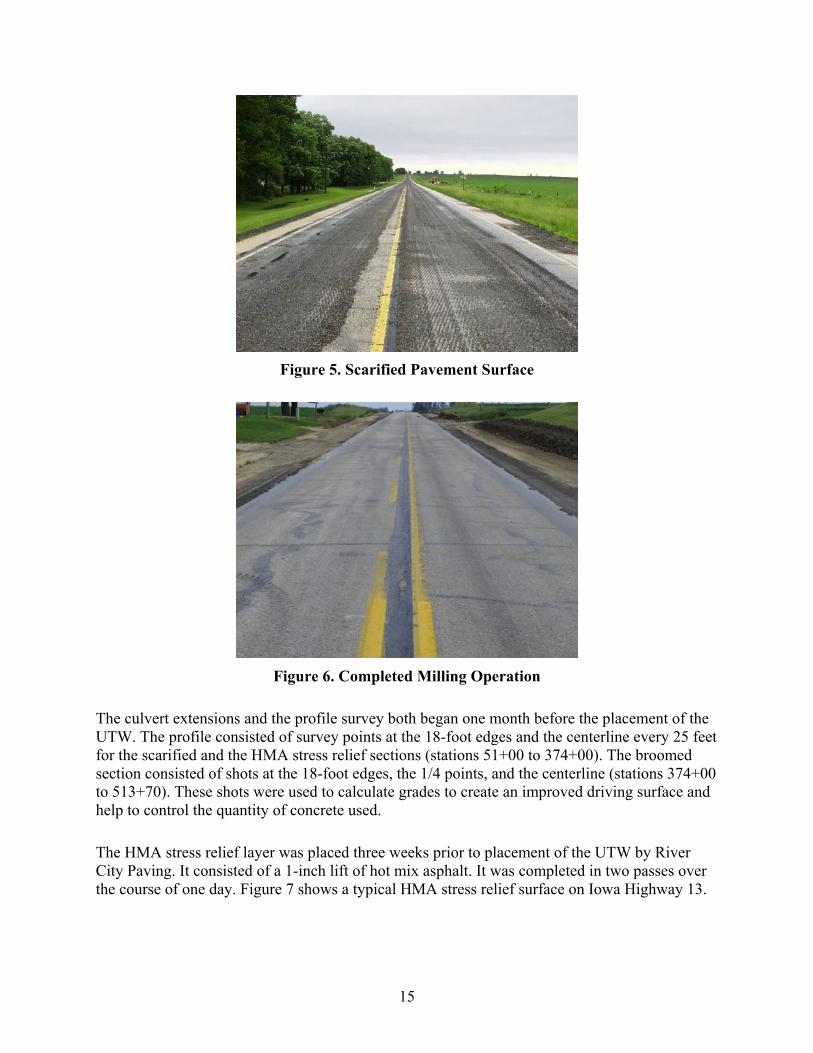
Scarification of the asphalt surface from station 51+00 to station 208+00 was performed two months prior to the UTW. The goal of the scarification was to remove the top layer, 1/4 inches, of oils and road grime to create a surface that the concrete would bond to easily. A 6-foot-wide Wirtgen 900 DC milling machine was used to remove the upper ACC layer. The milling machine followed the crown of the road and completed the work in four passes. Debris from the scarification was transported and piled on the shoulder using a loading belt mounted to the front of the milling machine. Figure 5 shows a typical scarified pavement surface on Iowa Highway 13.
The scarification of the above-described section was completed in two days, after which the milling of the asphalt widening unit began. The outer 3 feet of the asphalt widening unit was removed in order to bring the roadway back to the original 18 feet, which has a concrete base underneath it. The depth of the milling varied from 3.5 inches to 4.5 inches, dependant upon the thickness of the concrete to be placed in the overlay, so a constant 8-inch-thickened edge was created on each side of the roadway. The milling operation was followed by a motorgrader that pushed the shoulder material into the ditch and created a stable surface for the slip-form paver tracks to be supported upon. Figure 6 shows a typical milled widening unit on Iowa Highway 13.
15
Figure 5. Scarified Pavement Surface
Figure 6. Completed Milling Operation
The culvert extensions and the profile survey both began one month before the placement of the UTW. The profile consisted of survey points at the 18-foot edges and the centerline every 25 feet for the scarified and the HMA stress relief sections (stations 51+00 to 374+00). The broomed section consisted of shots at the 18-foot edges, the 1/4 points, and the centerline (stations 374+00 to 513+70). These shots were used to calculate grades to create an improved driving surface and help to control the quantity of concrete used.
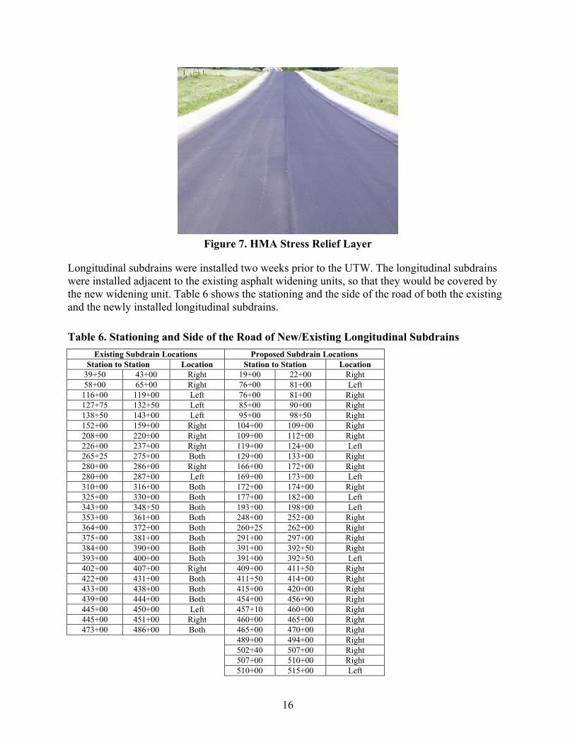
The HMA stress relief layer was placed three weeks prior to placement of the UTW by River City Paving. It consisted of a 1-inch lift of hot mix asphalt. It was completed in two passes over the course of one day. Figure 7 shows a typical HMA stress relief surface on Iowa Highway 13.
16
Figure 7. HMA Stress Relief Layer
Longitudinal subdrains were installed two weeks prior to the UTW. The longitudinal subdrains were installed adjacent to the existing asphalt widening units, so that they would be covered by the new widening unit. Table 6 shows the stationing and the side of the road of both the existing and the newly installed longitudinal subdrains.
Table 6. Stationing and Side of the Road of New/Existing Longitudinal Subdrains Existing Subdrain Locations Proposed Subdrain Locations
Station to Station Location Station to Station Location 39+50 43+00 Right 19+00 22+00 Right 58+00 65+00 Right 76+00 81+00 Left
116+00 119+00 Left 76+00 81+00 Right 127+75 132+50 Left 85+00 90+00 Right 138+50 143+00 Left 95+00 98+50 Right 152+00 159+00 Right 104+00 109+00 Right 208+00 220+00 Right 109+00 112+00 Right 226+00 237+00 Right 119+00 124+00 Left 265+25 275+00 Both 129+00 133+00 Right 280+00 286+00 Right 166+00 172+00 Right 280+00 287+00 Left 169+00 173+00 Left 310+00 316+00 Both 172+00 174+00 Right 325+00 330+00 Both 177+00 182+00 Left 343+00 348+50 Both 193+00 198+00 Left 353+00 361+00 Both 248+00 252+00 Right 364+00 372+00 Both 260+25 262+00 Right 375+00 381+00 Both 291+00 297+00 Right 384+00 390+00 Both 391+00 392+50 Right 393+00 400+00 Both 391+00 392+50 Left 402+00 407+00 Right 409+00 411+50 Right 422+00 431+00 Both 411+50 414+00 Right 433+00 438+00 Both 415+00 420+00 Right 439+00 444+00 Both 454+00 456+90 Right 445+00 450+00 Left 457+10 460+00 Right 445+00 451+00 Right 460+00 465+00 Right 473+00 486+00 Both 465+00 470+00 Right
489+00 494+00 Right 502+40 507+00 Right 507+00 510+00 Right 510+00 515+00 Left

17
In the broomed-only section of the project, a bridging technique was used determine the minimum amount of surface preparation that could be performed and still obtain desirable overlay performance. Areas of the pavement that were in extremely poor condition having multiple transverse cracks and extensive faulting existed. Six cracks with this degree of distress were bridged with #4 coated epoxy rebars stapled to the slab. The bars were 36 inches long and placed 30 inches on center perpendicular to the direction of the crack. Figure 8 show the bars stapled to the slab before they were overlaid with concrete. Table 7 shows the stations at which the transverse cracks were tied in this manner.
Figure 8. Tied Transverse Crack
Table 7. Tied Transverse Crack Locations
1 2 3 4 5 6 Station 385+98 396+33 404+82 409+65 418+00 456+66 Due to the high number of changing variables being tested on this project, the Iowa State University staff created signs that alerted construction workers to changes in jointing patterns, fiber inclusion, and beginning and ending points of the tied outer joints. Figure 9 shows the labeling plates that were placed throughout the length of the project alerting of changes.

18
Figure 9. Labeling Plate
Paving operations took place from July 2 to July 23, 2002. After subtracting rain days and holidays, the 9 miles of paving was completed in 12 working days. The PCC mixes used were Quality Management–Concrete (QMC) mixes designed by Fred Carlson Company.
Materials were stored, proportioned, and mixed at a portable central mix PCC plant located at the north end of the project, in Kuhlman’s Quarry on the west side of the town of Edgewood, Iowa. Agitator trucks and dump trucks transported the mix to the construction location. Power brooming was conducted just prior to the placement of the PCC. The brooming was done to remove loose pavement or contaminants on the ACC surface. Also prior to placement, in test sections that required, the 18-foot joints on either side of the pavement were tied with #4 by 3-foot epoxy coated steel bars. These bars were stapled to the pavement at 30-inch intervals in an effort to connect the 8-inch widening unit to the thin, unbonded pavement. Figure 10 shows the bars stapled to the asphalt slab prior to being covered by concrete.
Due to the high daytime temperature during the construction of this project, water was used to control the temperature of the ACC base. The Iowa State University staff monitored the temperature of the subbase with infrared temperature guns. When the base reached 100 degrees Fahrenheit, the base was sprayed with water. The water was placed on the existing surface, an adequate length in front of the slip-form paver, so that by the time the paving train would pass by, evaporation of standing water had already occurred and the pavement cooled to a safe level.

19
Figure 10. Stapled #4 Bar that Ties the Widening Unit to the Thin Overlay
A CMI Caterpillar SF-550 slip-form paver, with electronic horizontal and vertical grade control, was used to pave both lanes of the project simultaneously. Horizontally projected vibrators provided consolidation of the concrete. Following vibration, the PCC was struck off to achieve final thickness and a two percent crown. Attached to the bottom of the pan were two longitudinal joint forming knives. The knives separated the aggregates, leaving a weakened joint of concrete cream 2 inches deep. The knives were attached to the pan 9 feet from the centerline on each side of the pan. The use of the longitudinal joint forming knives on this project eliminated 17.5 miles of joint sawing. Figure 11 shows the longitudinal joint forming knife as it was attached to the bottom of the pan.
Figure 11. Longitudinal Joint Forming Knife

20
Following the paver, bullfloating and initial texturing were performed by construction workers. The construction workers were followed by a Guntert and ZimmermanTC-850, which performed the longitudinal tining and sprayed the 1600 White curing compound on the exposed portions of the slab. The outer 2.5 feet of each side of the slab was not tined in order to create a natural shoulder appearance on the slab.
The sawing of joints began as soon as the concrete was set enough to support the equipment, typically 3 to 4 hours after the application of the curing compound. Sawing of the transverse joints continued until raveling occurred; at that time the operation was paused for 30 to 60 minutes to allow for more set time. The joints were cut in a way to form 4.5 x 4.5, 6 x 6, and 9 x 9 foot square panels. Figure 12 is a diagram that shows how the joint patterns were laid out on the slab.
Figure 12. Typical of Panel Sizes
Longitudinal joints were sawed 3 hours after the transverse joints, and they were sawed from south to north. The rate of placement required as many as three saws being used simultaneously in order keep up with the paving operation.
Since a 1/8-inch joint width was used, the joints were not sealed, but they were cleaned. The process of cleaning the joints consisted of a high-pressure air blast, which would drive the concrete dust out of the joint and off the slab.

21
Three varieties of synthetic fiber reinforcement were used on this project—polypropylene fibrillated, polypropylene monofilament, and structural fibers. All fibers on this project were provided by W.R. Grace. The fibers were added at 1 pound of monofilament per cubic yard of concrete, 3 pounds of fibrillated polypropylene fibers per cubic yard of concrete, and 3 pounds of structural fibers per cubic yard of concrete. The fibers were blown into the concrete mixing drum by use of a hopper system supplied by W.R. Grace. Figure 13 shows the operation of the fiber inclusion system.
Figure 13. Fibers Being Blown into the Concrete Mixing Drum
The strength development for this project was measured using the maturity method. Temperature probes were inserted 100 feet from the end point of each test section. A 7.5-inch probe was inserted one foot from the pavement edge and monitored the temperature at depths of 1, 4, 7.5 inches. Another probe was placed in the thin overlay section six feet from the pavement edge and monitored the temperature at depths of 1 and 2 inches. One set of probes was placed 100 feet from the end of each of the 91 test sections. The temperature was read from these probes four times daily, Monday through Friday, to determine the time-temperature factor, which can be correlated to concrete flexural strength. The center portion of the new roadway was open to local traffic at a flexural strength of 350 psi, and construction traffic was allowed on the slab at 500 psi as determined by the maturity probes. The slab could be opened to local traffic the day after it was placed; however, local traffic was not allowed on until two days after in an effort to protect the paving equipment and the workers.
A separate agreement was made with the Federal Highway Administration–Iowa Division to test multiple maturity devices on the same project. The objectives of this work were to provide an evaluation of various types of maturity measuring equipment in a side-by-side demonstration of the materials and methods. For a full report about the testing and evaluation of these devices, see Appendix A.
Construction Concerns
Difficulties were encountered on numerous occasions in trying to reach a balance between overrun, achieving the appropriate thickness, and maintaining a smooth ride. These problems

22
were the result of the survey/grade not being finished until after paving began. The grades had to be calculated in a rush, not allowing time to input corrective measures into the design of the new roadway. In an effort to control the concrete overrun, the Iowa DOT lowered the grades, and as a result the ride measured by the profilograph suffered.
The use of fibers caused concerns for construction workers who were trying to finish the slab, especially when using the structural fibers at the end-of-day joints. As a result, the fiber inclusion was stopped both in and out of the headers at the conclusion and the beginning of each day. If the paving was stopped in a test section that included fibers, the last two truckloads of the day were mixed without fibers. The same was true for the first two truckloads that were mixed in the morning. This change allowed for smoother headers and easier finishing. The tining process caused the fibers to stand up making the surface of the slab look “hairy.” All of the surface fibers were worn away after a few days of highway traffic. During the second day of paving, large concentrations of fiber were seen in the concrete. This was found to be caused by a lack of suction in the blower to evenly distribute the fibers throughout the concrete in the mixing drum. To create more suction, a small cardboard piece was held over the opening of the blower after the fibers had been emptied into the blower. All clumps disappeared after use of the cardboard piece. Figure 14 shows how the cardboard piece was used to create increased blowing power.
Figure 14. Adjustment to Blower for Better Fiber Dispersion
The 1-inch HMA stress relief layer that was placed over the existing asphalt retained a large amount of heat in the midday sun. Even after one application of water, the temperature of that surface was measured to be 120 to 130 degrees Fahrenheit. Questions arose as to what effect the heat would have on bond between the slabs and the strength gain of the slab.
The longitudinal joint forming knife was leaving a wide gap behind the paver. As a result, it required extra passes from the workers using the bullfloats to properly close the gap. In an experiment, the joint forming knife on the right side of the pan was cut off at the backside of the pan on July 16, 2002. The aggregates were still being separated and the workers were able to

23
properly close the gap with one pass. Due to the success of the previous day, the left knife was cut off at the back of the pan on the next day.
At station 81+00 to station 81+50, the right-side pad of the paver was stuck in the mud; as a result, the paver pivoted, bringing the left pad into the edge of the fresh concrete. The excess concrete during the pivot forced the paver pan upward, creating a bump. A great deal of handwork was required to finish the slab, which was particularly difficult because of the use of the structural fibers. From station 85+00 to station 96+00, a sudden rainstorm saturated the slab before it could be covered. The slab from 87+50 to 96+00 was able to be longitudinally tined and resprayed with curing compound. The slab from 85+00 to 87+50 was too set to re-tine and sustained visible damage to the surface. From 101+75 to 102+75, plant problems caused the concrete to sit in front of the paver for about one hour before it was finished. After the plant was repaired, the concrete was sprayed with water and progress resumed.
Other construction concerns were quickly remedied, causing only minor delays. Other concerns included rainstorms, running out of fibers, and other equipment breakdowns.
Field Changes
Since the fiber inclusion cannot be started and stopped immediately, it sometimes ran short or over the beginning or end of the test section. Table 8 shows the adjusted beginning and ending stations and which types of fibers were used.
During construction, questions were raised on the validity of blowing the concrete dust out of the joints after they had been sawed. Like the longitudinal joint forming knife, the saw had already created a plane of weakness for the concrete to crack if needed. Since the joints were not going to be filled, the cleaning of the joints may be unnecessary. As a result, the Iowa State University staff set out two test sections along the project to test the effects of not cleaning the joints. These test sections were located from 258+00 to 265+00 and from 495+00 to 513+66.
On the first day of paving, there was confusion between the specifications for the width of the concrete joints. As a result, the joints in the first and second day of paving were sawed with a 1/4-inch blade instead of the specified 1/8-inch blade. The 1/4-inch joints were not sealed and the problem was eliminated before the third day’s paving was sawed. The 1/4-inch blade was used from station 51+02 to station 97+35.
The original proposal had called for surface patching of rough areas as one of the asphalt surface preparations. This was not done because of the overall good condition of the existing asphalt surface. As a result, the sections that were identified to be surface patched were simply broomed prior to construction.
The original proposal had also called for the existing joint to be either bridged with concrete or cut to match the cracks of the base PCC layer. All of the joints on this project were bridged with concrete.

24
Table 8. Adjusted Beginning and Ending Stations of Fiber Inclusion Section Station to Station Length Fiber Type
3-8 51+02 66+00 1,498 B 14 66+00 66+90 90 No
15-21 66+90 86+00 1,910 C 22-30 86+00 107+75 2,175 No 31-40 107+75 139+15 3,140 A
41 139+15 140+10 95 No 42-48 140+10 158+75 1,865 B
49 158+75 159+80 105 No 50-56 159+80 179+25 1,945 C 57-68 179+25 209+00 2,975 No 69-75 209+00 229+00 2,000 A
76 229+00 230+05 105 No 77-83 230+05 247+55 1,750 B
84 247+55 248+60 105 No 85-87 248+60 258+25 965 C 88-92 258+25 270+31 1,206 No
93 270+31 274+25 394 C 94-103 274+25 294+65 2,040 No
104-110 294+65 314+25 1,960 A 111 314+25 315+25 100 No
112-116 315+25 326+44 1,119 B 326+44 326+44 0 Header - two loads in and two out with no fibers
116-118 326+44 334+25 781 B 119 334+25 335+50 125 No
120-126 335+50 354+00 1,850 C 127-135 354+00 374+98 2,098 No 136-142 374+98 393+75 1,877 A
143 393+75 395+00 125 No 144-150 395+00 414+00 1,900 B
151 414+00 414+75 75 No 152-153 414+75 419+45 470 C
419+45 419+45 0 Header – two loads in and two out with no fibers 153-158 419+45 434+50 1,505 C 159-167 434+50 458+01 2,351 No 168-174 458+01 472+00 1,399 A
175 472+00 472+50 50 No 176-182 472+50 490+80 1,830 B
183 490+80 491+50 70 No 184-186 491+50 497+25 575 C - ran out of C fibers 187-191 497+25 513+66 1,641 No

25
TEST FREQUENCY AND METHODS
Lab Shear Testing
Lab testing involved shear testing on cores from the length of the project to test the bond between the new concrete overlay and the existing asphalt overlay. Three cores were taken from each of the specified locations to be tested in the lab. The cores were removed from the center of three consecutive panels within the given test section at the specified stationing. The cores were tested using the Iowa DOT Office of Materials Test Method #Iowa 406-C. Table 9 shows the results of the shear test and information about where the cores were taken from.
Table 9. Information and Results of Shear Test Thickness Sample Station Lane Overlay ACC Old PCC Total
Shear Strength (psi)
1 58+00 NBL 3.75 2.75 8.00 14.50 207 2 58+00 NBL 3.75 2.75 7.75 14.25 194 3 58+00 NBL 3.75 2.75 8.25 14.75 180 1 73+00 NBL 4.75 3.50 7.50 15.75 184 2 73+00 NBL 4.75 3.75 7.50 16.00 156 3 73+00 NBL 4.50 3.75 7.00 15.25 200 1 98+00 NBL 6.00 3.75 7.00 16.75 152 2 98+00 NBL 5.75 4.00 7.00 16.75 175 3 98+00 NBL 5.75 3.75 7.00 16.50 200 1 115+00 NBL 4.75 2.75 7.50 15.00 183 2 115+00 NBL 4.50 2.50 — 7.00 204 3 115+00 NBL 4.50 2.75 7.00 14.25 150 1 215+00 SBL 4.50 4.00 7.50 16.00 177 2 215+00 SBL 4.50 4.50 7.50 16.50 203 3 215+00 SBL 4.50 4.00 7.25 15.75 153 1 235+00 SBL 4.25 3.25 7.25 14.75 120 2 235+00 SBL 4.25 3.25 7.50 15.00 135 3 235+00 SBL 4.25 3.25 7.75 15.25 158 1 271+00 SBL 3.75 4.25 6.75 14.75 110 2 271+00 SBL 4.00 4.25 6.75 15.00 197 3 271+00 SBL 4.00 4.25 6.75 15.00 168 1 281+00 SBL 4.50 4.25 7.00 15.75 139 2 281+00 SBL 4.50 4.25 7.00 15.75 144 3 281+00 SBL 4.50 4.25 7.00 15.75 153 1 376+00 NBL 4.00 5.25 8.50 17.75 282 2 376+00 NBL 4.00 5.00 8.00 17.00 300 3 376+00 NBL 4.00 5.00 8.00 17.00 475 1 401+00 NBL 4.25 4.75 7.75 16.75 211 2 401+00 NBL 4.25 4.75 7.50 16.50 212 3 401+00 NBL 4.25 4.50 7.75 16.50 264 1 426+00 NBL 5.00 4.50 7.00 16.50 360 2 426+00 NBL 5.00 4.50 7.25 16.75 460 3 426+00 NBL 5.00 4.50 7.00 16.50 290 1 436+00 NBL 4.25 7.50 — 11.75 269 2 436+00 NBL 4.50 7.50 — 12.00 270 3 436+00 NBL 4.25 7.00 — 11.25 228

26
Field Testing
Falling Weight Deflectometer Testing
Falling weight deflectometer (FWD) testing was conducted before and after the construction of the project. It will be done biannually, once in the fall and once in the spring, for the next five years. Before construction, the original pavement structure was tested in the outer wheel path of the north and southbound lanes. Each location was tested once. After construction, the new pavement was tested in the same spots twice a year, once in October and once in April.
Testing is conducted by the Iowa DOT Ames Office using a Foundation Mechanics JILS-20-FWD with a 6-inch load plate and nine displacement measuring sensors. One transducer is located at the center of the load plate, and the remaining transducers are spaced at varying intervals from the plate. Figure 15 shows the location of the deflection sensors in relation to the load.
Figure 15. Schematic of FWD Deflection Sensors
The computer and system processor controlled testing operations and recorded maximum deflection responses measured by each transducer. At each of the test locations, drops were made at a target load of 9,000 pounds. A drop sequence was performed at each test location at the transverse joint and at the slab center along the outer wheel path. Appendix B contains the data for the FWD testing that was done before construction and after construction. Test locations were established to provide replicates of the test variable combinations and direction of travel. Testing locations are also shown in Appendix B with the FWD data.
Joint Openings and Faulting Measurements
Twice a year the staff from Iowa State University measures the joint openings and the faulting of 10 consecutive transverse joints located at the center of each test sections. During the construction process, nails were placed on each side of the transverse joints 10 inches apart and 1 foot from the edge of the northbound lane. The distance between the nails is measured and

27
recorded to determine the effects of the changing climate on the pavement surface. The faulting is measured using a faultmeter at the same 10 transverse joints that were measured for joint openings. The faulting is read 4.5 feet from the outer edge of both the northbound and southbound lanes. Appendix C contains joint opening data and the faulting data that have been collected since construction.
Visual Distress Surveys
Following the construction of the project, visual distress surveys have been conducted. The types of distresses considered in the survey include transverse cracks, longitudinal cracks, corner cracks, diagonal cracks, popouts, joint spalls, and fractured panels. Surveys are conducted twice per year, one in October and the other in April. The tests were performed to identify the impact of the freeze thaw cycles and the impact of heavy loads on pavement performance.
Visual distress survey results from two walking surveys are not conclusive, but provide some insight into long-range performance related to overlay design features. Working centerline joints cannot be bridged with concrete up to 4.5 inches in depth without expecting some reflective cracking. One such instance has occurred in the first year in a 6-foot-wide panel that bridges the only centerline.
In one area of the project, the existing ACC materials were almost completely removed to allow the new surface to meet and existing concrete road at an intersection. This was the tradeoff to removal of a large amount of relatively new county road approach PCC. This resulted in effectively building a bonded overlay in this short area. It is performing well, but care should have been taken to match new and existing joints. By continuing the normal joint pattern for the test section, we have observed two transverse cracks and one longitudinal centerline crack.
Weigh-in-Motion Device Measurements
A weigh-in-motion device was installed at station 340+00. It records the number of axels and the weight of the axels that pass that particular point. The device monitors the traffic in both the northbound and southbound lanes. The data will be useful in future analysis of the overlay variables versus pavement performance.
Cross Sectional Structural Analysis
During the course of the planning and construction of this project, the project team questioned the design and purpose of the widening units to the overall performance of the overlay. The widening units appeared to contain the overlay and provide edge support or act as a paved shoulder for the existing pavement width. A finite elemental structural analysis was conducted to determine the value of the overlay and widening units in the reduction of stress and strain applied to the original pavement. The intent of this work was to aid in determining some of the expected performance enhancements from the overall design.

28
The pavement was analyzed in terms of two designs, one without the widening units and one with the widening units of PCC. The study considered variations in subgrade support, cross slope, and joints at each edge of the original pavement width.
Results of the deflection analysis indicate a 40 percent reduction in stresses as the subgrade support value is doubled or the assumed values for design are reached. A 60 percent reduction in deflection values is noted when the widening units are added to the pavement cross section. See Appendix D for additional information regarding the cross sectional structural analysis.
SUMMARY
The Iowa Highway 13 project was developed efficiently and according to acceptable construction practices. The team of the Iowa DOT, Iowa State University, and Fred Carlson Company created an award-winning project. Due to the constant interaction with neighbors affected by the construction and the timely opening of the road to traffic, the project won the Traffic Management Award from the Iowa Concrete Paving Association. The construction concerns were relatively minor, with the exception of the difficulty in maintaining a balance between pavement thickness, concrete overruns, and ride.
Proper construction and recording of the project performance measures should provide a solid basis for data collection and analysis. Ultimately, it is desired to develop a construction specification on how to design a thin, unbonded concrete overlay in terms of joint spacing, PCC thickness, surface preparation, use of fibers, and the sealing of joints. The number and range of design variables will prove valuable to such research efforts.
REFERENCES
Cable, J.K., J.M. Hart, and T.J. Ciha. 1999. Thin Bonded Overlay Evaluation. Construction Report. Department of Civil and Construction Engineering, Iowa State University, Ames, Iowa.
Iowa Department of Transportation. 2001. Standard Specifications for Highway and Bridge Construction. Iowa Department of Transportation, Ames, Iowa.
U.S. Department of Agriculture. 1986. Soil Survey of Delaware County, Iowa. U.S. Department of Agriculture, Washington, D.C.

APPENDIX A
MATURITY MEASUREMENT EQUIPMENT EVALUATION: FINAL REPORT

A-1
J.K. Cable, M.L. Anthony
Maturity Measurement Equipment Evaluation
Final Report
May 2003
Sponsored by the Federal Highway Administration,
U.S. Department of Transportation
U.S. DOT Ref. No. 2-0019-100 Iowa State University Continuing Education

A-2
Technical Report Documentation Page
1. Report No. 2. Government Accession No. 3. Recipient’s Catalog No. U.S. DOT Ref. No. 2-0019-100
4. Title and Subtitle 5. Report Date May 2003 6. Performing Organization Code
Maturity Measurement Equipment Evaluation
7. Author(s) 8. Performing Organization Report No. J.K. Cable, M.L. Anthony 9. Performing Organization Name and Address 10. Work Unit No. (TRAIS)
11. Contract or Grant No.
Continuing Education Iowa State University Ames, IA 50011 12. Sponsoring Organization Name and Address 13. Type of Report and Period Covered
Final Report 14. Sponsoring Agency Code
Federal Highway Administration U.S. Department of Transportation Washington, DC 20590 15. Supplementary Notes 16. Abstract Since 1995, Iowa has been leading the way to greater use of the maturity concept in portland cement concrete pavement construction. New technologies have emerged to further that concept. The Federal Highway Administration and Iowa State University teamed to evaluate four temperature-monitoring systems: (1) Iowa Maturity Device, (2) Total Environmental Management for Paving System (Transtec Group, Inc.), (3) IRD Concrete Maturity Monitor (International Road Dynamics), and (4) IntelliROCK System (Nomadics Construction Laboratory). Side-by-side evaluation was conducted on 12 sites in a nine-mile pavement overlay project. Each device performed well and gave corresponding temperature values. The attributes and limitations of each device are described in this report. The specific devices with memory are well suited to structural concrete temperature monitoring. In the case of highway pavements, ease of installation and operation, wireless remote data transmittal, and minimal cost remain the goals to be achieved.
17. Key Words 18. Distribution Statement portland cement concrete pavement overlays, maturity, temperature-monitoring systems
No restrictions.
19. Security Classification (of this report)
20. Security Classification (of this page)
21. No. of Pages 22. Price
Unclassified. Unclassified. 16 NA

A-3
INTRODUCTION
Background
In recent years, the Iowa Department of Transportation has conducted research through Iowa State University (ISU) that resulted in the implementation of the maturity concept for estimating the strength of portland cement concrete pavements in the field. This work has allowed the department and the contracting industry to reduce the amount of time between concrete placement and opening of the pavement to traffic from seven days to two or less in many cases. Contractors have embraced the concept and it is employed on a majority of state projects in Iowa at this time.
ISU, through its Department of Civil, Construction, and Environmental Engineering and Center for Portland Cement Concrete Pavement Technology, is currently under contract to conduct research on the “Evaluation of Composite Pavement Unbonded Overlays.” As part of this work, maturity is to be used to measure estimated strength gain in the concrete to allow for early opening. The project team and the Federal Highway Administration (FHWA) Iowa Division entered into a separate agreement to test multiple maturity devices on the above-described project.
Objectives
The objectives of this work are to provide an evaluation of various types of maturity measuring equipment in a side-by-side demonstration of the materials and methods. The methods considered are as follows:
1. Iowa Maturity Device—conventional thermocouple wires and digital thermometers (part of the current research contract) employing the Iowa Maturity Device.
2. Total Environmental Management for Paving (TEMP) System—Electronic buttons with wire antennas and remote access (provided by Transtec Group, Inc., as a subcontract in current research).
3. IRD Concrete Maturity Monitor—Concrete maturity monitor by International Road Dynamics (IRD) with memory and remote access (under evaluation by the FHWA Midwest Resource Center).
4. IntelliROCK System—IntelliROCK System by Nomadics Construction Laboratory, including sensors with memory capability and lead wires and a physical logger system.
RESEARCH METHODOLOGY
The current research was conducted on Iowa Highway 13 in Delaware County between the north city limits of Manchester, Iowa, and Iowa Highway 3 (9.45 miles). There were 92 separate test sections provided to test base preparation methods, overlay depth, joint spacing, and fiber inclusion. The 28-foot roadway was constructed with one pass of a slip-form paver over the top of an existing 18-foot concrete roadway overlaid with two asphalt layers. The four types of
A-4
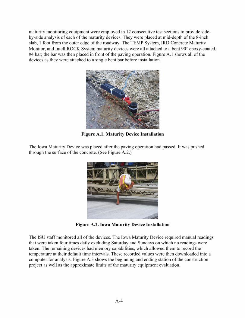
maturity monitoring equipment were employed in 12 consecutive test sections to provide side-by-side analysis of each of the maturity devices. They were placed at mid-depth of the 8-inch slab, 1 foot from the outer edge of the roadway. The TEMP System, IRD Concrete Maturity Monitor, and IntelliROCK System maturity devices were all attached to a bent 90° epoxy-coated, #4 bar; the bar was then placed in front of the paving operation. Figure A.1 shows all of the devices as they were attached to a single bent bar before installation.
Figure A.1. Maturity Device Installation
The Iowa Maturity Device was placed after the paving operation had passed. It was pushed through the surface of the concrete. (See Figure A.2.)
Figure A.2. Iowa Maturity Device Installation
The ISU staff monitored all of the devices. The Iowa Maturity Device required manual readings that were taken four times daily excluding Saturday and Sundays on which no readings were taken. The remaining devices had memory capabilities, which allowed them to record the temperature at their default time intervals. These recorded values were then downloaded into a computer for analysis. Figure A.3 shows the beginning and ending station of the construction project as well as the approximate limits of the maturity equipment evaluation.

A-5
Figure A.3. Project Map

A-6
MATERIALS
Iowa Maturity Device
Figure A.4. Iowa Maturity Device
The Iowa Maturity Device (see Figure A.4) is a 4-inch wood dowel with two sets of thermocouple wires attached to it. The device is able to measure the real-time temperature of the concrete at depths of 1 inch and 4 inches when a digital thermometer is connected to the proper leads. In the comparison with the other maturity monitors, the 4-inch depth was used. The 4-inch depth was selected because it was located in the middle of the 8-inch-thick widening unit as well as being the same depth the other maturity monitors were installed. The Iowa Maturity Device requires manual reading and recording of all temperature values. These reading are placed into a spreadsheet that calculates the time-temperature factor (TTF). It is a destructive testing method that is employed after the paving train has already gone by. The Iowa Maturity Device was used to monitor the strength gain of the concrete to control opening times for this project. The concrete was monitored up until a 500-psi flexural strength was attained. At this point, the wires were cut at the pavement surface, and only the buried wooden dowel was left in the concrete. As a result, the Iowa Maturity Device controlled the amount of data provided in the graphs of time vs. temperature and time vs. TTF, which only include data up through 100 hours.

A-7
TEMP System (Transtec Group, Inc.)
Figure A.5. TEMP System (Transtec Group, Inc.)
The Total Environmental Management for Paving (TEMP) System (see Figure A.5) is comprised of concrete temperature gages similar to those used by modern maturity systems, as well as an inexpensive laptop or handheld computer loaded with the TEMP System software product. An optional antenna station can be included as an add-on to the system in order to transmit downloaded data to a location within a one-mile radius.
The sensor currently used by the TEMP System is an iButton, manufactured by Dallas Semiconductor and modified for use in concrete construction. Each iButton is a rugged, self-sufficient system that records up to 2,048 temperature values taken at uniform time intervals ranging from 1 to 255 minutes. An interval of 5 minutes was used during this project. If the temperature leaves a user-programmable range, the iButton will also record when this happened, for how long the temperature stayed outside the permitted range, and if the temperature was too high or too low. A total of 24 such events can be recorded, 12 exceeding each temperature limit. Data are transferred via a serial connection on a personal computer (PC). The TEMP System is a nondestructive monitoring device that is placed in the flow of concrete in front of the paving train. However, it does contain wire leads that need to be protected for the remainder of the construction process. The wires are cut at the pavement surface when testing is complete, and only the buried iButton is left in the concrete.

A-8
IRD Concrete Maturity Monitor (International Road Dynamics)
Figure A.6. IRD Concrete Maturity Monitor (International Road Dynamics)
The IRD Concrete Maturity Monitor (see Figure A.6) is a 1-1/4 inch by 5 inch by 1 inch tag that contains a thermometer, memory for storage, and a remote transmitter. The default setting is to record the temperature every half hour, but this can be changed to any desired interval. The default half-hour interval was used for this research. The required iPaq Pocket PC with antenna iCard, dimensions 3-1/2 inches by 5-1/4 inches by 2 inches, is able to download data from the tag into the Pocket PC’s memory via a wireless transmission. The data can be exported in a comma-separated file to be used with Microsoft Excel on any computer. The tag records and exports the following data:
• Tag serial number • Location of the tag (if saved to the tag during construction) • Logging interval • Start/end time of the tags recording • Number of times recording was taken • Average temperature of all the records • High temperature of all the records • Low temperature of all the records • Time and temperature data for every interval from start/end time
The tags are initialized before being placed in front of the paving train. After initialization, the tags will record the temperature at the set interval. The tag is a nondestructive monitoring device that is placed in the flow of concrete in front of the paving train. It does not need to be pushed into the surface of the concrete, nor does it contain wire leads that need to be protected. The tags

A-9
have a limited memory dependant upon the logging interval, but can be reinitialized and begin recording again until battery failure.
IntelliROCK System (Nomadics Construction Laboratory)
Figure A.7. IntelliROCK System (Nomadics Construction Laboratory)
The IntelliROCK System (see Figure A.7) is a 1-1/2 inch by 1-1/8 inch cylinder that contains a thermometer and memory for storage. The logger is programmed to record the temperature of the concrete at 0, 4, 12, 24, 48, 72, 96, 120, 144, and 168 hours. The logger uses these recorded temperatures to calculate the maturity of the concrete using the Nurse-Saul Method at a user-selected datum (-10°C was the datum for this project). The IntelliROCK System also records the minimum and maximum temperature and the time that it occurred. The required maturity reader is used to download the data from the loggers using a wire connection. This data can be exported from the reader to a computer in a Microsoft Excel file. The IntelliROCK System records and exports the following data:
• Serial number • Datum temperature that was used • Temperature and calculated maturity (degree-hours) at 0, 4, 12, 24, 48, 72, 96,
120, 144, and 168 hours • Maximum temperature and time it occurred • Minimum temperature and time it occurred • Current temperature and maturity at time of download
The IntelliROCK logger is a nondestructive monitoring device that is placed in the flow of concrete in front of the paving train. However, it does contain wire leads that need to be

A-10
protected for the remainder of the construction process. The wires are cut at the pavement surface when testing is complete, and only the buried logger is left in the concrete. The IntelliROCK loggers are initialized after they have been paved over and have a battery life of 3 months from that time.
ANALYSIS
Table A.1 ranks each of the maturity devices on six characteristics of their use. A “5” means the device is excellent, and a “1” means the device performed poorly when compared to the other maturity devices.
Table A.1. Equipment Comparison
Equipment Iowa Maturity Device
TEMP System
IRD Concrete Maturity Monitor
IntelliROCK System
Ease of installation 2 3 4 3
Ease of use 3 4 2 5
Training requirements 4 3 2 4
Durability 2 3 4 3
Flexibility 2 3 4 3
Total 13 16 16 18 Ease of Installation and Use
Iowa Maturity Device
Ease of Installation 2
Ease of Use 3
The Iowa Maturity Device was installed after the paving train had passed, by pressing it into the surface of the concrete. It is a destructive testing method that mars the surface of the concrete. It does not contain memory for storage; therefore, it must be read by manual means at the specified interval.
TEMP System
Ease of Installation 3
Ease of Use 4
The TEMP System is made up of a small, button-sized recorder that was attached to a #4 rebar ahead of the paving operation. The recorder contained wire leads that needed to be buried in order for the paving operation to pass by safely. After the concrete is placed, the

A-11
TEMP System contains a memory system in which it records the temperature of the concrete at the user specified interval. The temperature data are stored and can be downloaded straight into a software program. The TEMP System has the option of connecting an antenna to the wire leads in order to transmit the downloaded data to a location within a one-mile range. The software is programmed to calculate the maturity in both Fahrenheit and Celsius degree-hours.
IRD Concrete Maturity Monitor
Ease of Installation 4
Ease of Use 2
The IRD Concrete Maturity Monitor, a remote system, was also attached to a #4 rebar ahead of the paving operation. It also contains a memory system that records the temperature of the concrete at the user-specified interval. The temperature data were stored and available for download at anytime. The IRD system uses an iPaq Pocket PC in order to communicate with the buried tag. The tag must be initialized before they are buried in order to begin recording temperatures. After initialization, the Pocket PC should be held directly above the tag in order to download the temperature data from the tag via radar. However, the research crew had a number of problems communicating with the tags. Once the tags were buried in the concrete, it often took 8–10 attempts before a connection was established between the tag and the Pocket PC. The software has the ability to calculate the maturity in both Fahrenheit and Celsius degree-hours. It can also calculate the flexural strength of the slab if the proper data were inputted to the tag. All of the location and mix information is saved to the tag, but the research team had a major problem with the tags not saving the data. When future readings were made, the saved location data and mix information was not on file.
IntelliROCK System
Ease of Installation 3
Ease of Use 5
The IntelliROCK System was placed ahead of the paving operation in the same manner as the TEMP System. It contains a memory system that records the temperature of the concrete, but at programmed intervals of 0, 4, 12, 24, 48, 72, 96, 120, 144, and 168 hours. The IntelliROCK System also needs to be initialized in order to begin recording temperature data. The IntelliROCK System comes with an easy-to-use reader that can be connected to the wire leads. Once connected, one button operation allows the user to download the data into a self-contained spreadsheet, which calculates the maturity in Celsius degree-hours. The IntelliROCK System comes with software that can be loaded onto a desktop PC that facilitates reception of the downloaded data.

A-12
Training Requirements
Iowa Maturity Device
Training Requirements 4
The Iowa Maturity Device is a very basic system. All that is required is knowledge of how to connect the thermocouple wires to a digital thermometer. The digital thermometer display gives a visual readout of the temperature for manual recording.
TEMP System
Training Requirements 3
Information on the training requirements was not available for the TEMP System at the time of this test. A representative was on site during the research testing to complete all of the necessary procedures.
IRD Concrete Maturity Monitor
Training Requirements 2
The IRD Concrete Maturity Monitor comes with software that must be loaded onto the iPaq Personal PC. The tags and the software come with a nine-section instruction manual that explains the requirements and procedures for use. The IRD system also requires that the user be familiar with how to use an iPaq Personal PC. A moderate amount of technological knowledge was required to use the system, combined with a couple of hours of reading the supplied instruction manuals.
IntelliROCK System
Training Requirements 4
The IntelliROCK System comes with a short instructional manual and unlike the IRD Concrete Maturity Monitor is very simple to use. The supplied reader has a very simple display and allows the user to complete most commands with the press of one button. The supplied IntelliROCK software package can download the saved data to a computer with the press of one button. A minimal amount of technological knowledge was required to use the IntelliROCK System.

A-13
Durability
Iowa Maturity Device
Durability 2
The Iowa Maturity Device is very susceptible to damage from the construction process. The Iowa Maturity Device uses very lightweight thermocouple wires; as a result, the wires were often damaged while lying on the pavement surface. Another problem was the wires losing contact with each other when being inserted into the concrete. These two problems resulted in the loss of temperature data and therefore an unknown concrete maturity. However, of the 12 sites that were monitored for this project, none of the wire leads was damaged by construction traffic.
TEMP System
Durability 3
The TEMP System also uses a wire lead that is susceptible to damage. However, the wire lead is much thicker than the one used in the Iowa Maturity Device and was able to withstand damage from the construction process. None of the wire leads used on this project was damaged by construction traffic.
IRD Concrete Maturity Monitor
Durability 4
The IRD Concrete Maturity Monitor does not contain any wire leads that can be damaged. Once safely placed in the concrete, it was not affected by any part of the construction process. The IRD system had problems obtaining readings through concrete of depths greater than 4 inches or containing large amounts of water. The thicker and the wetter the concrete, the harder it was to get a reading from the tag. Obtaining readings through the concrete could be completed after several trials, but the researcher must always be aware of how deep the tag is being placed to ensure that a proper reading can be obtained.
IntelliROCK System
Durability 3
The IntelliROCK System is much like the TEMP System in that it has a wire lead that needs to be protected. The wire lead is also much thicker then the one used with the Iowa Maturity Device, but the research team did have some problems with a couple of the IntelliROCK wires being damaged during construction. Of the 12 sites that were

A-14
monitored for this project, two of the wire leads were damaged by construction traffic and data were unable to be downloaded from these sites.
Flexibility
Iowa Maturity Device
Flexibility 2
The quality of thermocouple wires that are used and the type of digital thermometer limit the Iowa Maturity Device’s effectiveness. The personnel that are available to read the devices also limit it. The device can, however, be employed on a variety of projects from highway to structural.
TEMP System
Flexibility 3
The TEMP System is a nondestructive test. The user can also set it to record temperature data at any time increment from 1 to 255 minutes. Its versatility allows it to be utilized on a variety of projects, from highway to structural.
IRD Concrete Maturity Monitor
Flexibility 4
The IRD Concrete Maturity Monitor is also a nondestructive test. Because it does not have wires that need to be protected, it is more flexible. Like the TEMP System, it can be set to record temperature data at any time increment that is desired by the user. It is easily attached to structural rebar and can be employed in all aspects of concrete construction.
IntelliROCK System
Flexibility 3
The IntelliROCK System is a nondestructive test that requires the protection of the wire leads. However, it limits temperature readings to 0, 4, 12, 24, 48, 72, 96, 120, 144, and 168 hours. It could be utilized on a variety of projects, from highway to structural.

A-15
Limitations
Iowa Maturity Device
The simplicity limits the Iowa Maturity Device. The Iowa Maturity Device was
monitored regularly and provided effective results in predicting concrete strength.
However, it requires personnel to be on site to take readings at the prescribed interval.
TEMP System
The only limitation with the TEMP System was the wire leads that need to be protected.
IRD Concrete Maturity Monitor
After working with the IRD Concrete Maturity Monitor, it was evident that the software
was trying to do too much. The software has many features, but one of its flaws is in
saving data to the tags. Most of the time, the information that was sent to the tags was not
recorded. Another problem was communicating with the tags. After burying the tags in
the concrete, it often took repeated trials in order to connect with the tag. Finally, to
ensure a proper reading, the PC had to be placed right on top of the slab.
IntelliROCK System
Like the TEMP System, the IntelliROCK System has wire leads that need to be protected.
Another limitation was the low number of times that temperatures were recorded in the
first 72 hours of initial pavement curing. However, IntelliROCK System also makes a
logger that records temperatures at intervals that are more frequent. This type of device
would have improved the comparison of data between maturity devices.
Cost
Table A.2 presents a cost comparison.

A-16
Table A.2. Cost of the Maturity Monitor Components
Component Iowa
Maturity Device
TEMP System
IRD Concrete Maturity
Meter
IntelliROCK System
Reading meter or computer $100.00 $1,000.00 $800.00 $875.00
Antenna support system $0.00 $495 each (optional) $1,083.00 $0.00
Software $0.00 $795.00 $775.00 $0.00
Logging device $5.00 each $30.00 each $4.87 each $25.00 each
Number of sites used at 12 5 12 12
Contractor Evaluation of Potential Use
At the current time, it is the feeling of a number of the contractors in Iowa that the industry is not ready to move to computer-managed products. The contractors that were questioned about their use said that they would be better suited for use in structural applications. What they would like to see is an inexpensive device that can continually monitor temperatures. Another wish is to get the maturity monitoring off the slab to avoid damage during the construction process.
CONCLUSIONS
• Each of the devices evaluated yield comparable results.
• Differences in maturity for each device are primarily associated with the frequency of
data collection.
• Maturity required to open the pavement to traffic can be accurately obtained with a
minimum of four temperature values per day to collect the maximum and minimum
temperature values.
• The current Iowa method is most widely accepted for pavements due to minimum cost
and labor availability.
• Devices with memory (e.g., the TEMP System, IRD Concrete Maturity Meter, and
IntelliROCK System) are well suited to structural monitoring for temperature
maintenance.
• Future direction should focus on reduced cost and wireless sensors with a 1–10 mile
range for construction applications.

APPENDIX B
FALLING WEIGHT DEFLECTOMETER DATA

B-1
Table B.1. Preconstruction FWD Data (Performed on 5/21/2002 on Previous Existing Asphalt Roadway Surface) Sensor Number
Test #
Lane
Station
Load (kips) 1 2 3 4 5 6 7 8 9
Temp (ºF)
1 North 43+02 9.06 4.75 3.91 3.67 3.49 3.25 2.76 2.3 1.79 3.56 53.1 2 North 52+94 9.17 5.53 5.43 5.25 4.99 4.68 4.05 3.41 2.79 4.99 53.5 3 North 63+03 9.06 6.59 5.74 5.4 4.96 4.51 3.62 2.87 2.21 5.75 53.8 4 North 73+08 9 7.55 7.41 7.24 6.92 6.52 5.6 4.66 3.75 7.21 53.5 5 North 83+13 8.89 7.43 7.31 7.29 7.18 7.05 5.57 4.32 3.24 6.64 54.2 6 North 93+00 8.79 0.52 9.53 9.21 8.66 8.26 7.12 5.85 4.45 9.3 53.5 7 North 103+09 8.65 7.52 7.13 6.79 6.29 5.86 4.84 3.9 3.31 5.94 54.6 8 North 113+27 8.97 6.39 5.97 5.86 5.61 5.34 4.67 3.95 3.28 5.77 54.2 9 North 123+09 8.78 6.65 6.36 6.23 5.91 5.58 4.81 4.01 3.26 5.96 54.2
10 North 133+03 8.8 3.78 3.66 3.58 3.44 3.3 2.99 2.69 1.71 3.29 53.8 11 North 143+00 8.81 3.37 3.13 2.96 2.81 2.69 2.38 2.07 1.77 2.88 52.4 12 North 152+80 8.83 6 5.24 5.06 4.89 4.65 4.06 3.45 2.85 5.01 55.7 13 North 163+02 8.78 7 6.6 6.3 5.96 5.38 4.57 3.79 3.09 5.47 55.7 14 North 173+12 8.8 6.71 5.79 5.41 5.04 4.71 3.85 3.15 2.44 5.32 54.6 15 North 186+22 8.94 7.04 6.03 5.71 5.37 5.01 4.19 3.35 2.61 5.8 55.3 16 North 195+10 8.9 7.4 6.24 5.78 5.38 4.97 4.11 3.26 2.56 6.24 55.7 17 North 205+12 8.34 7.2 6.91 6.59 6.16 5.63 4.57 3.63 2.8 5.83 54.6 18 North 215+22 8.51 7.92 7.27 7.09 6.78 6.35 5.38 4.42 3.48 6.99 54.2 19 North 225+34 8.35 6 5.85 5.8 5.59 5.17 4.28 3.48 2.77 5.41 56 20 North 235+41 8.46 7.43 6.93 6.67 6.28 5.87 5.01 4.2 3.51 7.64 57.1 21 North 245+64 8.4 5.53 5.2 5.11 4.91 4.66 4.03 3.38 2.71 4.9 56.4 22 North 255+59 8.33 6.29 5.69 5.22 4.55 3.94 2.85 2.07 1.61 5.07 54.6 23 North 268+29 8.03 10.3 10.18 10.13 10.06 9.95 6.59 5.48 4.43 9.29 56.8 24 North 278+47 8.41 8.3 8.21 8.12 7.94 7.72 6.68 5.4 4.19 7.64 55.7 25 North 289+31 8.48 6.88 6.32 6.06 5.83 5.58 4.93 4.25 3.52 6.01 56 26 North 298+06 8.47 6.61 6.56 6.54 6.46 6.39 5.79 4.85 3.97 6.18 54.9 27 North 308+11 8.53 6.75 6.13 5.9 5.69 5.46 4.87 4.3 3.69 6.04 55.7 28 North 328+10 8.24 8.4 7.73 7.35 7.01 6.71 6.11 5.43 4.78 7.03 55.3 29 North 328+17 8.36 7.94 6.99 6.64 6.3 5.98 5.32 4.48 3.73 6.61 55.3 30 North 338+19 8.48 8.64 7.84 7.44 7.1 6.85 6.17 5.29 4.48 7.27 55.7 31 North 348+23 8.4 11.05 10.35 10.18 9.93 9.62 8.87 7.95 7.05 10.34 51.6 32 North 358+32 8.22 8.96 8.12 7.84 7.53 7.19 6.32 5.42 4.47 7.82 55.3 33 North 368+44 8.3 8.47 7.22 6.78 6.4 6.03 5.25 4.44 3.61 7.11 52.7 34 North 377+94 8.35 13.32 11.54 10.97 10.45 9.98 8.88 7.72 6.56 11.58 51.6 35 North 388+04 8.36 9.06 7.64 7.16 6.68 6.22 5.27 4.41 3.63 7.96 56 36 North 398+59 8.31 7.45 6.55 6.12 5.71 5.37 4.66 3.97 3.32 6.25 56.4 37 North 408+09 8.25 5.63 5.11 4.96 4.82 4.59 4.03 3.4 2.85 4.85 56 38 North 417+89 7.89 5.47 5.59 5.26 4.94 4.5 3.59 2.74 2.22 4.46 56.4 38 North 419+49 8.39 13.51 11.06 9.38 7.65 6.27 4.29 3.1 2.23 9.9 55.7 39 North 428+02 8.37 7.64 6.96 6.76 6.55 6.3 5.63 4.9 4.24 6.71 56 40 North 437+08 8.12 12.11 11.23 10.83 10.26 9.69 8.43 7.27 6.19 12.25 56.8 41 North 447+90 8.34 8.47 7.64 7.22 6.77 6.34 5.44 4.52 3.61 8.25 56 42 North 459+03 8.11 10.02 9.04 8.7 8.35 7.96 7.06 6.13 5.17 9.2 54.6 43 North 465+36 8.41 9.43 8.39 7.82 7.31 6.91 6.02 5.1 4.26 8.22 57.9 44 North 475+02 8.18 6.28 6.1 5.92 5.74 5.54 5 4.4 3.74 5.8 59.7

B-2
45 North 484+11 8 9.2 8.67 8.51 8.2 7.79 6.86 5.76 4.7 8.52 58.2 46 North 491+10 8.12 7.79 7.34 7.19 6.9 6.55 5.66 4.72 3.81 6.93 58.2 47 North 500+16 8.39 7.19 6.89 6.74 6.47 6.13 5.31 4.47 3.67 6.69 59.7 48 North 508+19 8.35 5.15 5.01 4.89 4.67 4.43 3.85 3.26 2.7 4.9 59.7 49 North 517+42 8.23 8 7 6.33 5.4 4.57 3.18 2.18 1.8 7.06 56.4 50 North 518+92 8.24 6.03 5.36 4.93 4.35 3.82 2.84 2.09 1.69 4.74 57.9 1 South 525+02 8.18 6.15 5.6 5.17 4.57 4 2.91 2.07 1.66 4.89 58.2 2 South 508+30 8.39 8.57 7.95 7.68 7.25 6.75 5.73 4.77 3.86 8.48 58.2 3 South 498+74 8.56 9.34 8.69 8.46 8.05 7.64 6.66 5.65 4.7 8.86 57.9 4 South 489+67 8.33 8.39 7.92 7.63 7.34 7.03 6.18 5.13 2.55 7.37 57.1 5 South 480+01 8.04 6.41 5.8 5.61 5.46 5.26 4.73 4.11 3.47 5.34 58.2 6 South 470+04 8.24 7.3 6.36 5.9 5.41 4.99 4.11 3.28 2.5 6.11 58.6 7 South 462+84 8.28 8.54 7.45 7.12 6.88 6.58 5.81 5.05 4.27 7.28 58.6 8 South 450+85 8.01 6.9 6.22 5.8 5.44 5.21 4.71 4.03 3.45 5.61 57.5 9 South 441+05 8.41 9.51 9.04 8.9 8.62 8.29 7.4 6.46 5.44 8.91 58.6
10 South 431+08 8.19 7.36 6.84 6.34 5.98 5.71 5.11 4.47 3.78 5.95 60.1 11 South 420+99 8.45 6.85 6.24 6.04 5.78 5.48 4.73 3.97 3.22 6.22 59.7 12 South 411+34 8.34 8.13 7.53 7.29 7.01 6.74 6.06 5.29 4.56 7.74 59.7 13 South 401+13 8.53 6.73 5.91 5.67 5.44 5.16 4.51 3.82 3.22 5.73 58.6 14 South 391+07 7.96 8.96 8.21 7.8 7.42 7.07 6.2 5.33 4.47 8.71 59.7 15 South 381+43 8.31 7.84 7.37 7.23 6.99 6.7 5.98 5.19 4.39 7.26 59.7 16 South 371+00 8.22 8.03 7.07 6.54 5.96 5.49 4.68 3.89 3.15 6.5 59.7 17 South 360+76 8.14 7.64 7.37 6.78 6.31 5.9 4.92 4.02 3.22 6.34 59.7 18 South 350+83 8.15 8.62 7.73 7.43 7.08 6.72 5.9 5.05 4.22 7.34 60.1 19 South 340+67 8.51 8.61 8.18 8 7.74 7.48 6.75 5.91 5.09 8.14 59.7 20 South 331+00 8.48 7.14 6.63 6.44 6.23 6.01 5.38 4.7 3.99 6.37 59.7 21 South 321+05 8.09 8.24 7.65 7.53 7.35 7.1 6.38 5.56 4.74 7.43 59.3 22 South 310+86 8.28 7.54 6.48 6.22 5.93 5.6 4.84 4.08 3.38 6.17 60.8 23 South 300+87 8.11 9.04 8.75 8.59 8.27 7.91 7.03 5.97 4.57 8.63 59.7 24 South 291+14 8.31 5.85 5.47 5.29 5.05 4.78 4.18 3.57 3 5.5 53.1 25 South 279+94 8.01 9.45 8.65 8.26 7.91 7.42 6.37 5.33 4.33 7.78 63 26 South 270+96 8.06 12.63 10.73 10.04 9.15 8.29 6.62 5.25 4.06 10.86 63 27 South 260+26 8.03 7.14 6.42 5.89 5.18 4.54 3.38 2.5 2.09 7.01 60.4 28 South 250+05 8.03 6.5 6 5.84 5.51 5.16 4.37 3.59 2.86 6.04 62.6 29 South 240+08 8.36 5.63 5.42 5.31 5.1 4.73 3.83 3.05 2.34 5.09 62.6 30 South 230+05 7.96 6.19 6.15 6.09 5.96 5.73 4.77 3.95 3.26 5.71 51.6 31 South 219+35 8.14 8.56 8.49 8.49 8.35 7.66 6.14 4.85 3.7 7.2 64.8 32 South 209+93 8.03 6.2 5.97 5.83 5.57 5.26 4.47 3.68 2.93 5.74 63.7 33 South 199+95 8.26 7.51 5.8 5.03 4.52 4 3.09 2.39 1.77 4.92 65.2 34 South 189+83 8.11 5.63 4.81 4.61 4.42 4.18 3.57 2.92 2.33 4.56 64.5 35 South 175+90 8.11 6.21 6.05 5.94 5.74 5.49 4.93 4.37 2.26 5.88 63.4 36 South 165+87 8.44 5.64 5.2 5.07 4.87 4.65 4.04 3.4 2.75 5.05 64.5 37 South 155+59 7.92 3.48 3.28 3.18 3.04 2.92 2.69 2.5 2.37 3.02 64.5 38 South 144+80 7.92 7.93 7.21 6.74 6.25 5.82 4.88 4.02 3.15 6.68 66.3 39 South 136+24 8.34 5.61 4.96 4.81 4.64 4.44 3.9 3.36 2.76 4.59 63.4 40 South 126+07 8 8.02 7.72 7.58 7.26 6.91 6.05 5.2 2.66 7.4 66.3 41 South 116+26 8.07 6.19 6.05 5.91 5.67 5.35 4.56 3.77 3.03 5.76 67 42 South 106+06 8.28 6.25 5.54 5.34 5.14 4.92 4.29 3.64 2.97 5.35 67.7

B-3
43 South 95+29 8.11 6.24 6.16 6.01 5.83 5.6 4.95 4.23 3.48 5.6 66.7 44 South 85+34 8.45 10.16 8.67 8.11 7.41 6.69 5.33 4.14 3.06 8.63 71.4 45 South 75+41 8.17 6.75 6.1 5.9 5.62 5.3 4.51 3.72 3 6.15 71.8 46 South 65+97 8.39 4.65 4.13 3.94 3.69 3.42 2.83 2.27 1.76 4.22 69.9 47 South 55+95 8.4 8.45 7.77 7.29 6.59 5.89 4.55 3.31 2.11 6.97 70.7 48 South 45+84 7.91 2.56 2.41 2.34 2.26 2.12 1.81 1.5 0 2.14 57.5

B-4
Table B.2. Postconstruction FWD Data (Performed on 8/7/2002) Sensor Number
Test #
Lane
Station
Location
*
Load (kips) 1 2 3 4 5 6 7 8 9
Temp (ºF)
1 North 53+25 2 8.97 3.17 2.83 2.61 2.37 2.2 1.87 1.61 1.36 2.69 89
2 North 53+27 1 8.94 2.89 2.68 2.54 2.39 2.25 1.97 1.7 1.43 2.52 89
3 North 63+25 2 8.81 2.71 2.51 2.34 2.19 2.02 1.78 1.51 0 2.36 89.4
4 North 63+29 1 8.79 2.82 2.64 2.51 2.34 2.17 1.85 1.55 0 2.35 90.1
5 North 73+25 2 8.89 3.19 2.97 2.85 2.7 2.55 2.29 2 1.75 2.78 89.7
6 North 73+28 1 8.78 3.48 3.24 3.12 2.97 2.74 2.41 2.03 1.74 2.98 89.4
7 North 83+30 2 8.54 4.41 3.43 3.26 3.02 2.82 2.39 1.97 1.65 3.36 89
8 North 83+33 1 8.69 3.46 3.19 2.95 2.75 2.57 2.25 1.92 1.61 3.03 89.7
9 North 93+32 2 8.76 3.16 2.92 2.72 2.53 2.37 2.07 1.78 1.66 2.76 86.1
10 North 96+64 1 8.52 2.8 2.61 2.48 2.33 2.2 1.97 1.73 1.71 2.46 91.2
11 North 103+32 2 8.67 3.65 3.49 3.19 2.92 2.72 2.37 2.02 1.67 2.97 89.7
12 North 103+35 1 8.31 3.35 3.12 2.91 2.63 2.47 2.18 1.9 1.73 2.83 91.6
13 North 113+41 2 8.53 4.42 3.44 3.26 3.03 2.84 2.41 2.04 1.81 3.47 90.1
14 North 113+44 1 8.73 4.14 3.08 2.9 2.72 2.58 2.27 1.95 1.7 3.04 90.1
15 North 123+40 2 8.7 4.09 3.89 3.66 3.45 3.25 2.88 2.39 1.88 3.53 91.9
16 North 124+44 1 8.61 4.97 4.66 4.31 3.83 3.41 2.76 2.27 1.87 4.12 93.8
17 North 133+41 2 8.64 2.7 2.55 2.38 2.23 2.08 1.91 1.75 0 2.27 90.8
18 North 133+43 1 8.47 3.27 3.12 2.94 2.68 2.41 2.07 1.79 0 2.69 91.2
19 North 143+48 2 8.69 2.79 2.59 2.36 2.08 1.86 1.51 1.3 0 2.18 92.3
20 North 143+56 1 8.72 3.01 2.61 2.35 2.09 1.9 1.67 1.45 0 2.37 91.9
21 North 153+52 2 8.69 2.58 2.32 2.12 1.93 1.79 1.57 1.38 0 2.18 92.3
22 North 153+52 1 8.75 2.47 2.17 2.03 1.88 1.74 1.57 1.35 0 2.07 93
23 North 163+44 2 8.61 3.03 2.77 2.58 2.36 2.22 1.99 1.78 0 2.54 94.1
24 North 163+47 1 8.29 3 2.79 2.63 2.43 2.28 2.06 1.85 0 2.55 93.4
25 North 173+51 2 8.29 4.72 3.65 3.33 2.94 2.64 2.12 1.73 1.45 3.44 94.8
26 North 174+24 1 8.37 3.9 3.44 3.13 2.78 2.53 2.1 1.72 1.42 3.16 96.3
27 North 183+52 2 8.62 3.99 3.83 3.52 3.22 3 2.57 2.15 1.97 3.33 97
28 North 183+56 1 8.62 3.15 3.04 2.98 2.89 2.78 2.51 2.17 2.09 2.95 96.7
29 North 186+57 2 8.11 4.07 3.29 3.02 2.72 2.47 2.04 1.67 0 3.21 97
30 North 186+60 1 8.39 3.99 3.51 3.19 2.79 2.49 2.06 1.75 1.48 3.27 97
31 North 195+51 2 8.75 5.01 4.02 3.62 3.17 2.87 2.36 1.95 1.53 3.75 90.8
32 North 195+54 1 9.05 4.71 4.16 3.77 3.27 2.88 2.31 1.85 1.46 3.66 93
33 North 205+54 2 8.8 3.84 3.55 3.18 2.8 2.55 2.15 1.8 1.54 2.97 94.1
34 North 206+08 1 8.65 3.27 2.92 2.72 2.55 2.38 2.04 1.76 1.26 2.78 97.8
35 North 215+53 2 9.05 3.12 2.85 2.65 2.46 2.3 2.02 1.74 1.48 2.6 92.7
36 North 215+55 1 9.17 3.14 2.89 2.68 2.5 2.34 2.06 1.74 0 2.63 93
37 North 225+63 2 8.85 4.63 3.02 2.85 2.65 2.46 2.07 1.72 0 3.03 76.5
38 North 225+63 1 8.97 2.92 2.62 2.46 2.3 2.16 1.86 1.57 0 2.57 76.2
39 North 235+56 2 9.07 3.52 2.95 2.8 2.64 2.44 2.09 1.77 0 2.83 92.7
40 North 235+60 1 8.89 2.93 2.68 2.48 2.32 2.17 1.92 1.71 0 2.6 94.1
41 North 245+65 2 8.58 2.57 2.41 2.27 2.09 1.96 1.71 0 0 2.17 90.1
42 North 245+67 1 8.95 2.62 2.43 2.31 2.15 2.05 1.85 1.64 1.39 2.28 91.2
43 North 255+65 2 8.42 4.16 3.9 3.5 2.96 2.55 1.89 1.47 0 3.27 92.3
44 North 255+68 1 8.96 3.81 3.44 3.19 2.81 2.51 1.96 1.57 0 3.21 91.9
45 North 268+68 2 8.3 4.72 4.38 4.1 3.76 3.5 3.05 2.64 2.29 4.06 94.1

B-5
46 North 268+72 1 8.65 3.52 3.33 3.22 3.08 2.94 2.68 2.43 2.15 3.29 94.1
47 North 278+68 2 9.16 3.92 3.77 3.55 3.31 3.08 2.72 2.4 2.05 3.43 94.8
48 North 278+71 1 8.42 3.44 3.3 3.16 2.99 2.74 2.4 2.09 0 3.11 93.8
49 North 288+69 2 8.73 3.24 2.97 2.75 2.51 2.32 2 1.74 0 2.75 95.9
50 North 288+73 1 9.08 3.19 2.95 2.78 2.58 2.41 2.06 1.8 0 2.75 95.2
51 North 298+70 2 9 3.01 2.84 2.71 2.58 2.48 2.25 2.04 1.84 2.72 93
52 North 299+65 1 8.83 3.01 2.84 2.73 2.6 2.49 2.26 2.03 1.81 2.71 97
53 North 308+68 2 8.92 3.24 2.94 2.84 2.68 2.54 2.21 1.91 0 2.81 94.5
54 North 308+71 1 8.59 3.37 3.1 2.9 2.61 2.42 2.11 1.86 1.7 2.87 93.4
55 North 318+72 2 9 3.64 3.41 3.26 3.09 2.94 2.69 2.43 2.19 3.22 94.8
56 North 318+00 1 8.25 3.56 3.38 3.23 3.07 2.95 2.56 2.25 1.95 3.11 94.1
57 North 327+97 2 8.69 5.12 4.61 4.18 3.7 3.34 2.8 2.37 2.04 4.38 95.2
58 North 327+99 1 8.85 4.49 4.1 3.8 3.42 3.17 2.72 2.32 1.96 3.76 94.8
59 North 337+94 2 8.73 4.34 4.06 3.8 3.51 3.32 3 2.63 2.39 3.71 94.5
60 North 337+98 1 8.7 4.58 4.29 4.03 3.71 3.49 3.06 2.63 2.32 3.89 96.3
61 North 348+03 2 8.86 5.71 5.48 5.19 4.86 4.56 3.91 3.25 2.73 5.1 93
62 North 348+07 1 8.69 5.84 5.48 5.16 4.74 4.39 3.75 3.17 2.71 5.22 93
63 North 358+05 2 8.75 3.77 3.57 3.38 3.2 3.05 2.76 2.44 2.13 3.34 96.7
64 North 358+09 1 8.79 3.87 3.65 3.49 3.25 3.05 2.65 2.3 2.01 3.4 95.9
65 North 368+04 2 8.8 4.15 3.89 3.55 3.21 2.93 2.45 2.06 1.68 3.39 79.8
66 North 368+07 1 8.81 5.27 3.73 3.44 3.1 2.85 2.37 1.97 1.62 3.42 80.2
67 North 378+02 2 8.63 5.53 4.94 4.63 4.28 3.98 3.47 3 2.58 4.64 97.8
68 North 378+06 1 8.86 5.05 4.75 4.51 4.2 3.94 3.47 3.02 2.64 4.54 94.8
69 North 388+06 2 8.7 5.01 4.59 4.25 3.88 3.58 2.98 2.45 2 4.12 97.4
70 North 388+09 1 8.79 5.32 4.69 4.27 3.76 3.37 2.75 2.27 1.88 4.42 97
71 North 398+07 2 8.18 3.89 3.54 3.23 2.88 2.66 2.33 2.01 1.77 3.18 97.8
72 North 398+09 1 8.15 3.95 3.56 3.26 2.93 2.71 2.36 2.04 1.89 3.19 98.1
73 North 408+04 2 8.64 4.96 4.37 4.06 3.72 3.48 2.98 2.46 2.04 4.03 97
74 North 408+08 1 8.12 4.75 4.24 3.93 3.59 3.32 2.83 2.36 1.93 3.99 96.3
75 North 418+06 2 8.58 7.28 6.23 5.29 4.34 3.65 2.77 2.19 1.87 4.92 94.1
76 North 418+09 1 8.78 4.88 4.37 4.03 3.61 3.23 2.63 2.11 1.75 4.26 93.8
77 North 428+13 2 8.42 4.44 3.9 3.62 3.3 3.09 2.74 2.41 2.14 3.56 93.4
78 North 428+15 1 8.69 4 3.68 3.47 3.23 3.04 2.72 2.43 2.15 3.54 93.4
79 North 438+09 2 8.61 5.98 4.92 4.6 4.25 3.94 3.42 2.97 2.59 4.96 93
80 North 438+13 1 8.75 4.25 3.94 3.8 3.62 3.49 3.12 2.78 2.49 4.12 93
81 North 448+13 2 8.81 5.16 4.58 4.32 4.03 3.79 3.39 2.97 2.54 4.38 93.4
82 North 448+16 1 8.89 5.22 4.95 4.69 4.31 3.98 3.45 2.96 2.56 4.53 92.3
83 North 458+13 2 8.72 4.23 4 3.79 3.56 3.35 3.03 2.71 2.46 3.79 93.8
84 North 458+15 1 8.84 4.36 4.15 3.96 3.75 3.54 3.14 2.76 2.44 3.84 94.1
85 North 465+11 2 8.7 4.69 4.42 4.16 3.84 3.57 3.1 2.68 2.37 4.16 94.5
86 North 465+13 1 8.4 4.24 3.99 3.78 3.52 3.29 2.88 2.57 2.32 3.82 94.5
87 North 475+15 2 8.14 3.32 3.2 3 2.77 2.6 2.23 2.11 1.83 2.84 98.1
88 North 475+21 1 8.74 4.04 3.79 3.53 3.19 2.91 2.47 2.12 2.03 3.41 99.6
89 North 485+21 2 8.7 4.58 4.25 3.96 3.7 3.51 3.07 2.62 2.22 3.94 98.5
90 North 485+23 1 8.04 3.95 3.66 3.44 3.2 3.04 2.68 2.35 2.08 3.49 97.4
91 North 492+20 2 8.8 3.69 3.51 3.31 3.13 2.97 2.59 2.23 1.88 3.3 96.7
92 North 492+22 1 8.81 3.79 3.53 3.38 3.18 3.03 2.65 2.24 1.88 3.32 95.9
93 North 501+24 2 8.7 3.12 2.94 2.82 2.69 2.58 2.3 2.05 1.8 2.81 97.4

B-6
94 North 501+27 1 8.78 3.09 2.91 2.81 2.68 2.55 2.3 2.05 1.86 2.81 97.4
95 North 509+23 2 8.4 3 2.78 2.67 2.53 2.41 2.12 1.87 1.79 2.68 96.7
96 North 509+25 1 9.03 3.05 2.87 2.74 2.61 2.48 2.21 1.94 1.71 2.75 95.9
1 South 510+99 2 8.74 4.34 4.06 3.86 3.68 3.51 3.13 2.73 2.35 3.97 95.9
2 South 510+96 1 8.84 4.07 3.88 3.72 3.55 3.38 3.04 2.65 2.3 3.72 95.9
3 South 499+01 2 8.64 4.36 4.13 3.88 3.66 3.49 3.09 2.65 2.28 3.86 97.4
4 South 498+98 1 8.79 4.88 4.61 4.36 4.06 3.78 3.25 2.79 2.35 4.17 98.5
5 South 490+00 2 8.69 5.2 5.07 4.83 4.45 4.04 3.24 2.58 2.06 4.41 99.2
6 South 489+97 1 8.69 5.72 5.17 4.81 4.39 4.05 3.4 2.8 2.32 4.92 100
7 South 479+91 2 8.91 4.44 3.89 3.43 2.95 2.62 2.2 1.87 1.58 3.42 101.8
8 South 479+89 1 8.85 3.61 3.26 3.01 2.77 2.59 2.24 1.98 1.7 3.03 99.2
9 South 469+93 2 8.87 4.07 3.84 3.59 3.3 3.05 2.58 2.19 1.86 3.5 95.2
10 South 469+91 1 8.74 4.08 3.75 3.49 3.21 2.96 2.5 2.13 1.77 3.47 96.3
11 South 462+25 2 8.94 4.76 4.45 4.16 3.88 3.64 3.23 2.86 2.44 4.17 99.2
12 South 462+22 1 8.85 4.65 4.36 4.11 3.83 3.6 3.18 2.81 2.46 4.1 96.7
13 South 450+26 2 8.84 4.78 4.35 4.03 3.69 3.46 3.1 2.73 2.32 4.03 99.2
14 South 450+24 1 8.87 4.76 4.46 4.2 3.9 3.67 3.21 2.75 2.31 4.07 99.2
15 South 440+26 2 8.85 4.07 3.99 3.86 3.71 3.52 3.15 2.79 2.45 3.78 101.1
16 South 440+23 1 8.89 4.22 4 3.87 3.71 3.52 3.19 2.84 2.52 3.91 100.7
17 South 430+27 2 8.73 3.9 3.64 3.38 3.17 2.98 2.65 2.32 1.96 3.34 103.3
18 South 430+25 1 8.54 3.78 3.5 3.3 3.08 2.89 2.52 2.14 1.75 3.19 102.5
19 South 420+24 2 8.15 3.95 3.65 3.45 3.24 3.07 2.74 2.38 2.06 3.43 101.8
20 South 420+19 1 8.89 4.54 4.22 3.97 3.73 3.53 3.18 2.79 2.45 3.99 101.8
21 South 410+29 2 8.79 5.05 4.78 4.54 4.29 4.1 3.71 3.23 2.86 4.53 101.4
22 South 410+26 1 8.57 5.44 5.02 4.74 4.38 4.14 3.73 3.3 2.96 4.7 101.4
23 South 400+24 2 8.64 3.63 3.39 3.14 2.87 2.7 2.43 2.14 1.86 3.03 101.1
24 South 400+21 1 8.23 3.46 3.21 3.02 2.82 2.64 2.35 2.07 1.84 2.95 100
25 South 390+23 2 8.72 5.73 5.4 4.94 4.4 3.98 3.4 2.93 2.49 4.79 98.5
26 South 390+20 1 8.76 5.08 4.67 4.39 4.05 3.77 3.36 2.85 2.48 4.53 97
27 South 380+21 2 9.03 4.91 4.46 4.12 3.82 3.56 3.09 2.58 2.06 4.22 98.9
28 South 380+19 1 8.68 4.92 4.49 4.11 3.63 3.24 2.61 2.13 1.82 3.97 98.5
29 South 371+00 2 8.86 3.85 3.49 3.28 3.06 2.84 2.45 2.12 1.84 3.27 103.3
30 South 370+99 1 8.64 3.74 3.53 3.29 2.99 2.79 2.39 2.1 1.84 3.19 101.4
31 South 360+97 2 8.9 3.33 3.16 3.01 2.81 2.65 2.36 2.08 1.88 2.94 102.9
32 South 360+93 1 8.79 3.27 3.11 2.96 2.78 2.62 2.33 2.09 1.91 2.89 102.9
33 South 350+94 2 8.79 3.95 3.67 3.45 3.2 2.99 2.59 2.25 1.97 3.46 104.4
34 South 350+92 1 8.9 4.04 3.73 3.47 3.19 2.93 2.54 2.17 1.9 3.51 104.4
35 South 340+93 2 8.81 4.75 4.15 3.88 3.59 3.38 2.99 2.63 2.31 4.08 104
36 South 340+91 1 8.91 4.26 3.94 3.7 3.45 3.22 2.93 2.58 2.29 3.77 104
37 South 330+97 2 8.83 2.66 2.52 2.37 2.21 2.09 1.87 1.68 0 2.37 105.5
38 South 330+95 1 8.11 2.58 2.42 2.3 2.19 2.1 1.91 1.71 0 2.26 104
39 South 320+95 2 8.57 3.62 3.39 3.21 3.02 2.84 2.54 2.25 2.09 3.24 107.3
40 South 320+92 1 8.78 3.7 3.4 3.2 3.01 2.88 2.61 2.34 2.09 3.27 108
41 South 310+96 2 8.8 3.97 3.63 3.31 2.99 2.76 2.4 2.06 1.75 3.25 107.3
42 South 310+94 1 8.68 3.92 3.52 3.26 2.97 2.78 2.42 2.07 1.74 3.23 104.7
43 South 301+00 2 8.72 4.54 4.38 4.2 3.93 3.7 3.28 2.86 2.53 4.07 104
44 South 300+97 1 8.08 4.09 3.84 3.68 3.47 3.3 2.93 2.62 2.32 3.76 104.4
45 South 291+00 2 8.81 4.4 3.95 3.63 3.32 3.08 2.71 2.35 2.19 3.57 103.6

B-7
46 South 290+97 1 8.75 4.26 3.91 3.65 3.34 3.14 2.75 2.42 2.13 3.6 101.8
47 South 280+94 2 8.07 4.27 3.98 3.74 3.48 3.26 2.8 2.36 1.93 3.69 103.6
48 South 280+91 1 8.7 5.08 4.71 4.39 4.02 3.69 3.12 2.65 2.23 4.22 103.3
49 South 259+90 2 8.63 3.66 3.23 2.94 2.59 2.31 1.8 1.46 0 3.02 102.5
50 South 259+88 1 8.78 3.47 3.13 2.86 2.55 2.27 1.76 1.4 0 2.84 103.3
51 South 249+97 2 8.73 4.37 3.99 3.68 3.39 3.16 2.67 2.23 1.82 3.64 104.4
52 South 249+94 1 8.86 4.03 3.7 3.46 3.22 3.06 2.6 2.08 1.7 3.41 103.3
53 South 239+91 2 8.75 3.96 3.64 3.33 3.06 2.84 2.35 1.95 1.59 3.27 99.6
54 South 239+89 1 8.68 3.95 3.51 3.19 2.94 2.74 2.34 1.98 1.64 3.19 98.9
55 South 229+90 2 8.76 3.51 3.29 3.07 2.87 2.69 2.35 2.07 1.9 2.95 104.7
56 South 229+87 1 8.51 3.5 3.31 3.16 3.02 2.81 2.51 2.21 1.96 3.02 102.9
57 South 219+91 2 8.08 3.74 3.42 3.19 3.01 2.87 2.5 2.14 1.84 3.12 102.9
58 South 219+88 1 8.75 4.22 3.85 3.62 3.39 3.2 2.8 2.33 1.99 3.48 103.3
59 South 209+94 2 8.75 4.33 4 3.73 3.45 3.2 2.78 2.35 2 3.66 102.5
60 South 209+92 1 8.95 4.39 4.06 3.8 3.52 3.29 2.86 2.43 2.07 3.75 101.8
61 South 199+91 2 8.74 4.56 4.28 3.94 3.56 3.27 2.77 2.34 1.95 3.73 103.3
62 South 199+90 1 9 4.93 4.62 4.27 3.89 3.58 3.06 2.56 2.1 4.06 102.9
63 South 189+92 2 8.81 4.38 4.11 3.8 3.45 3.18 2.7 2.26 1.89 3.73 99.2
64 South 189+89 1 9 4.06 3.82 3.6 3.36 3.14 2.67 2.26 1.91 3.51 100.3
65 South 175+91 2 9.01 4.04 3.66 3.49 3.28 3.1 2.73 2.38 2.02 3.49 102.5
66 South 175+88 1 9.09 4.11 3.89 3.71 3.49 3.25 2.71 2.33 1.99 3.59 102.9
67 South 165+85 2 8.89 3.96 3.46 3.27 3.09 2.93 2.58 2.26 1.93 3.37 103.3
68 South 165+83 1 9.06 3.67 3.4 3.22 3.05 2.88 2.54 2.23 1.92 3.25 100.3
69 South 155+80 2 9.25 2.76 2.61 2.45 2.29 2.11 1.83 0 0 2.42 97.4
70 South 155+77 1 9.45 2.74 2.54 2.39 2.25 2.08 1.82 0 0 2.39 98.1
71 South 145+78 2 8.91 4.75 4.51 4.17 3.78 3.45 2.87 2.4 2.03 4 106.2
72 South 145+74 1 9.02 4.52 4.28 4.02 3.73 3.44 2.9 2.4 1.98 3.89 105.8
73 South 135+84 2 8.85 3.2 2.93 2.7 2.46 2.27 1.95 1.76 0 2.67 106.2
74 South 135+83 1 9.18 3.2 2.94 2.75 2.53 2.33 2.06 1.84 0 2.76 105.8
75 South 125+88 2 8.9 4.43 4.18 3.97 3.79 3.62 3.23 2.77 2.38 3.89 101.1
76 South 125+84 1 9.48 5.8 5.31 4.98 4.54 4.19 3.58 3.06 2.59 4.81 101.8
77 South 115+88 2 9.11 3.93 3.68 3.47 3.27 3.14 2.7 2.28 1.86 3.47 103.3
78 South 115+87 1 9.11 3.93 3.68 3.53 3.3 3.08 2.61 2.2 1.85 3.42 102.5
79 South 105+89 2 8.69 4.86 4.27 3.82 3.41 3.16 2.79 2.4 2.04 3.9 104
80 South 105+87 1 8.69 4.67 4.09 3.76 3.44 3.22 2.87 2.45 2.08 3.77 102.9
81 South 95+85 2 9.31 3.95 3.62 3.37 3.13 2.88 2.43 2.03 1.7 3.69 102.9
82 South 95+82 1 9.27 3.62 3.35 3.17 2.99 2.79 2.39 2.02 1.81 3.12 101.4
83 South 85+86 2 8.37 6.13 5.36 4.84 4.37 3.99 3.26 2.62 2.06 5.21 103.6
84 South 85+84 1 9.14 6.3 5.36 4.86 4.37 4.05 3.37 2.67 1.98 5.14 102.9
85 South 75+84 2 9.07 4.87 4.46 4.16 3.87 3.66 3.22 2.77 2.34 4.1 103.6
86 South 75+82 1 9.05 4.87 4.46 4.2 3.94 3.77 3.3 2.78 2.26 4.12 103.3
87 South 65+82 2 9 3.37 3.05 2.85 2.65 2.48 2.11 1.83 1.52 2.88 105.1
88 South 65+79 1 9.22 3.06 2.81 2.69 2.5 2.35 2.04 1.75 0 2.71 105.5
89 South 55+83 2 9.25 4.35 3.96 3.63 3.32 3.05 2.6 2.24 1.85 3.56 105.5
90 South 55+81 1 9 3.37 3.16 2.99 2.83 2.7 2.38 2.08 1.89 3.08 104 * 1 = midpanel deflection test, 2 = joint transfer deflection test.

APPENDIX C:
JOINT OPENING AND FAULTING DATA

C-1
Table C.1. Joint Opening and Fault Data Faulting Measurement Joint Opening (inches) NBL SBL NBL SBL Date 7/25/2002 10/11/2002 4/11/2003 10/12/2002 10/12/2002 4/12/2003 4/12/2003
Section Station 9 54+00. 9.81 9.82 9.76 -0.2 -0.3 -0.2 0.0 54+04.5 10.01 10.05 10.07 -0.1 -0.1 -0.5 0.0 54+09. 9.88 9.95 9.94 -0.2 0.5 -0.1 0.0 54+13.5 10.03 10.10 9.92 1.1 -0.3 -0.9 -1.0 54+18. 10.13 10.11 10.12 -0.3 -0.6 -0.8 0.0 54+22.5 9.99 10.03 9.99 1.1 0.4 -0.2 -1.0 54+27. 10.05 10.12 10.06 0.8 0.2 0.1 0.0 54+31.5 10.11 10.13 10.11 -0.8 1.0 -1.0 -2.0 54+36. 9.93 9.96 9.99 -0.4 -1.0 -1.0 0.0 54+40.5 10.15 10.20 10.08 0.2 0.1 -0.6 0.0
11 59+00. 9.95 9.97 9.95 1.1 0.1 -0.5 0.0 59+06. 9.98 10.01 9.96 -1.1 -0.8 -1.1 -1.0 59+12. 10.27 10.30 10.30 -0.2 0.0 0.2 0.0 59+18. 9.95 9.97 10.07 0.2 0.1 -0.6 0.0 59+24. 9.95 9.98 10.08 0.5 0.2 -0.5 0.0 59+30. 9.92 9.94 9.96 0.7 -1.3 -0.1 0.0 59+36. 9.98 10.03 10.02 0.2 -0.8 0.1 0.0 59+42. 9.94 9.94 9.96 0.7 -1.5 -0.2 0.0 59+48. 9.76 9.80 9.79 -0.8 0.3 -0.8 0.0 59+54. 10.15 10.19 10.19 -0.9 0.1 -1.2 -1.0
13 64+00. 9.67 9.64 9.65 -1.0 -0.5 -0.4 -1.0 64+06. 9.68 9.76 9.71 -0.8 0.4 0.2 -1.0 64+12. 10.09 10.11 10.11 -0.3 -0.8 -1.2 -1.0 64+18. 9.91 9.93 9.86 0.5 -0.3 0.1 0.0 64+24. 9.60 9.65 9.59 0.5 0.3 -1.3 0.0 64+30. 10.07 10.07 10.04 0.0 0.6 0.0 -1.0 64+36. 10.21 10.19 10.17 0.4 1.1 0.4 -1.0 64+42. 10.01 10.03 10.02 0.2 0.8 -1.0 0.0 64+48. 9.92 9.92 9.90 0.9 0.6 1.2 0.0 64+54. 10.03 10.14 10.12 0.5 -0.3 0.4 0.0
15 69+00. 9.97 9.98 9.96 -0.6 0.7 -0.5 0.0 69+06. 9.06 9.08 9.06 -1.0 0.9 -1.8 0.0 69+12. 8.93 8.92 8.91 0.3 -0.8 0.0 0.0 69+18. 9.26 9.33 9.25 1.0 -0.7 0.7 0.0 69+24. 9.16 9.21 9.16 1.0 0.4 -0.3 -1.0 69+30. 8.84 8.85 8.85 1.1 -0.6 0.7 0.0 69+36. 8.79 8.87 8.81 -0.3 0.7 0.5 0.0 69+42. 9.07 9.08 9.00 -0.6 0.3 1.0 0.0 69+48. 9.57 9.59 9.61 -1.3 0.7 -0.6 -1.0 69+54. 8.95 9.00 8.93 -0.5 -0.7 -1.0 -1.0
17 74+00. 9.89 9.95 9.90 0.2 1.0 0.9 0.0 74+06. 9.81 9.86 9.79 0.0 -0.3 0.3 0.0 74+12. 9.84 9.90 9.85 0.9 0.5 -1.0 0.0

C-2
74+18. 10.06 10.06 9.96 0.9 0.0 -1.3 -1.0 74+24. 10.36 10.36 10.27 0.4 0.0 -1.3 -1.0 74+30. 9.89 9.90 9.91 -0.7 -0.1 0.1 0.0 74+36. 9.97 10.00 9.96 0.9 0.5 0.7 -1.0 74+42. 9.91 9.94 9.94 0.5 -0.3 0.5 -1.0 74+48. 10.02 10.01 10.07 0.5 -1.0 -1.1 -1.0 74+54. 10.02 10.05 10.03 0.4 -0.3 -0.7 -1.0
19 79+00. 10.01 10.02 9.99 -1.3 -0.3 -0.7 0.0 79+06. 9.99 10.00 9.98 0.0 -0.3 0.2 0.0 79+12. 10.21 10.21 10.18 1.1 0.0 0.4 -1.0 79+18. 9.93 9.90 9.94 0.2 -0.2 -0.4 -1.0 79+24. 9.53 9.60 9.57 0.1 0.6 -0.3 -1.0 79+30. 9.68 9.72 9.82 0.7 -0.5 0.0 -1.0 79+36. 10.05 10.06 10.05 1.4 -0.9 -0.5 0.0 79+42. 10.08 10.06 10.04 0.1 -0.8 -1.0 0.0 79+48. 10.04 10.04 10.03 -1.3 -1.3 -0.8 0.0 79+54. 10.07 10.10 10.11 1.3 0.2 -1.5 -1.0
21 84+00. 10.06 10.11 10.07 0.3 -0.7 -0.6 0.0 84+06. 10.02 9.98 9.98 0.3 0.8 0.1 -3.0 84+12. 9.99 9.62 9.96 -0.8 1.0 0.5 -1.0 84+18. 10.04 10.07 10.10 1.0 2.2 0.9 -1.0 84+24. 10.23 10.24 10.27 -0.4 0.7 -1.0 0.0 84+30. 9.96 10.00 9.97 -0.3 -0.3 0.0 -1.0 84+36. 9.64 9.69 9.66 0.6 -0.8 0.2 -2.0 84+42. 9.92 9.95 9.92 0.0 -0.3 -0.4 -1.0 84+48. 10.08 10.11 10.09 -1.3 -1.0 0.5 -1.0 84+54. 10.19 10.23 10.19 0.3 1.2 0.7 0.0
23 89+00. 9.85 9.81 0.1 -0.5 0.0 0.0 89+04.5 10.16 10.21 -0.3 -0.3 0.5 0.0 89+09. 9.92 10.00 0.2 -0.4 -0.2 0.0 89+13.5 9.98 10.00 0.6 -0.3 -1.2 -1.0 89+18. 10.23 10.24 0.8 0.2 -0.5 -1.0 89+22.5 10.34 10.32 0.4 0.2 -0.8 0.0 89+27. 10.19 10.27 0.2 0.0 1.2 0.0 89+31.5 9.91 9.95 1.0 0.5 -0.4 -1.0 89+36. 9.85 9.86 0.4 1.8 -0.8 -1.0 89+40.5 10.47 10.50 0.2 0.3 0.2 0.0
25 94+00. -0.4 0.4 0.0 0.0 94+04.5 0.5 -1.0 0.6 0.0 94+09. 0.0 0.4 1.0 -1.0 94+13.5 0.1 -0.3 0.4 0.0 94+18. 0.5 0.8 0.8 0.0 94+22.5 1.3 -0.2 1.0 0.0 94+27. -0.9 0.4 -0.4 0.0 94+31.5 -0.5 1.5 0.0 -1.0 94+36. 0.9 1.5 -0.3 0.0 94+40.5 -0.7 1.3 0.2 -1.0
27 99+00. 1.0 -0.4 1.1 0.0

C-3
99+06. -0.6 -0.3 0.1 0.0 99+12. -0.9 -1.5 -0.9 -1.0 99+18. -1.0 0.2 -0.8 0.0 99+24. 0.0 -0.5 0.1 -1.0 99+30. 0.8 -0.2 0.5 0.0 99+36. 0.8 -0.3 0.0 0.0 99+42. -0.3 0.1 -1.0 -1.0 99+48. 0.5 -0.2 -1.0 0.0 99+54. 0.2 0.0 -0.5 -1.0
29 104+00. 9.59 9.65 9.66 0.6 0.1 -0.6 -1.0 104+06. 9.27 9.28 9.93 0.1 0.2 -0.2 0.0 104+12. 10.00 10.01 9.99 -1.0 -0.5 0.0 0.0 104+18. 9.49 9.50 9.55 0.4 1.0 0.0 0.0 104+24. 9.52 9.55 9.53 -1.5 0.2 -0.6 -1.0 104+30. 9.74 9.76 9.72 -0.6 0.5 -1.1 0.0 104+36. 9.58 9.55 9.56 -0.3 0.1 -1.0 -1.0 104+42. 9.83 9.86 9.83 0.0 -1.0 -0.7 -1.0 104+48. 9.46 9.50 9.46 0.6 1.1 -2.9 1.0 104+54. 9.77 9.81 9.79 0.0 -0.2 -1.3 0.0
31 110+00. 9.49 9.44 9.42 1.5 -1.3 0.3 0.0 110+06. 9.72 9.75 9.65 0.0 0.0 -0.8 -1.0 110+12. 9.49 9.47 9.47 0.1 -0.6 -0.7 0.0 110+18. 11.38 11.37 11.35 -0.3 -1.0 -0.4 0.0 110+24. 11.28 11.24 11.27 -0.5 -0.9 -0.6 0.0 110+30. 9.10 9.09 9.09 0.8 -0.3 0.7 -1.0 110+36. 9.65 9.67 9.69 1.0 -0.5 -0.5 0.0 110+42. 10.07 10.09 10.11 -0.2 0.0 -1.1 -1.0 110+48. 9.53 9.62 9.52 0.8 0.0 -0.5 0.0 110+54. 9.67 9.66 9.64 -0.9 0.3 -0.9 -1.0
33 116+50. 9.47 9.51 9.50 -1.3 -1.0 -0.5 0.0 116+54.5 9.11 9.09 9.73 -0.6 -0.7 0.6 0.0 116+59. 8.94 8.95 8.95 -0.5 -0.8 -0.5 0.0 116+63.5 9.11 9.11 9.10 -0.2 0.6 -1.0 -1.0 116+68. 9.23 9.21 9.23 0.0 0.1 0.8 0.0 116+72.5 9.42 9.45 9.44 0.5 0.2 0.7 0.0 116+77. 9.44 9.44 9.44 0.2 -1.3 -0.4 -1.0 116+81.5 9.62 9.64 9.67 0.2 -0.3 0.1 -1.0 116+86. 9.21 9.20 9.27 0.1 -0.4 -0.4 -1.0 116+90.5 9.54 9.62 9.56 2.0 -0.3 -0.8 -1.0 116+95. 9.91 9.91 9.92 -0.8 -0.8
34 122+00. 9.34 9.42 9.36 -0.9 -0.2 0.0 0.0 122+04.5 9.51 9.55 9.52 -0.3 -0.9 0.7 0.0 122+09. 9.09 9.06 9.06 0.4 -0.4 -2.3 0.0 122+13.5 9.71 9.73 9.72 -0.1 -0.2 0.1 0.0 122+18. 9.42 9.45 9.44 0.3 -0.1 -0.7 -1.0 122+22.5 10.12 10.10 10.09 -1.2 -0.4 -0.2 0.0 122+27. 8.94 8.97 8.93 0.8 -0.7 0.2 -1.0 122+31.5 9.81 9.83 9.80 0.8 -0.8 0.4 0.0

C-4
122+36. 9.94 10.00 9.97 -0.2 0.3 0.3 0.0 122+40.5 9.58 9.61 9.56 0.1 0.4 -0.8 0.0
36 126+00. -0.3 1.5 -0.3 -1.0 126+04.5 0.1 0.2 0.2 -1.0 126+09. -0.4 0.3 -0.3 0.0 126+13.5 0.5 0.7 -0.9 0.0 126+18. -0.2 -0.3 -0.6 -1.0 126+22.5 -0.2 0.3 -1.0 0.0 126+27. 0.7 0.6 -0.5 0.0 126+31.5 0.2 1.1 0.6 0.0 126+36. 0.4 0.4 0.1 -1.0 126+40.5 -0.3 -0.3 -0.7 1.0
38 132+00. 9.26 9.28 9.23 -0.3 0.5 0.6 -1.0 132+06. 9.71 9.83 9.76 -0.5 -0.5 -0.6 0.0 132+12. 8.90 8.95 8.90 0.0 0.2 -0.5 0.0 132+18. 9.09 9.14 9.11 -0.3 -0.2 -1.2 -1.0 132+24. 9.09 9.09 9.05 -0.3 0.0 -0.2 -1.0 132+30. 8.64 8.69 8.67 0.1 0.8 -0.7 0.0 132+36. 9.13 9.16 9.08 -0.7 0.0 -0.5 0.0 132+42. 9.51 9.60 9.58 0.2 -1.2 -0.8 -1.0 132+48. 9.73 9.91 9.89 0.0 0.4 -0.8 0.0 132+54. 8.41 8.46 8.42 -0.5 0.0 -0.5 -1.0
40 137+00. 9.24 9.28 9.33 -0.3 -0.1 0.5 0.0 137+06. 9.34 9.49 9.46 -0.4 0.7 -0.3 0.0 137+12. 9.01 9.01 9.01 -1.0 -0.4 -0.5 1.0 137+18. 9.92 9.98 9.95 -0.1 -0.1 -0.4 0.0 137+24. 9.55 9.58 9.54 -0.3 -0.5 -0.5 0.0 137+30. 9.68 9.69 9.64 -1.1 -0.1 -0.6 0.0 137+36. 9.59 9.60 9.56 -1.5 -0.1 -0.4 -1.0 137+42. 9.11 9.17 9.17 0.3 0.5 -0.3 0.0 137+48. 9.32 9.38 9.32 -0.3 -0.6 -0.7 0.0 137+54. 9.71 9.74 9.11 0.4 0.1 -0.5 0.0
42 142+00. 10.10 10.11 10.10 -1.0 0.0 0.0 0.0 142+04.5 9.72 9.76 9.72 0.1 0.7 -0.8 0.0 142+09. 9.53 9.55 9.53 0.3 -0.2 0.1 0.0 142+13.5 8.60 8.65 9.86 0.9 -0.7 0.7 -1.0 142+18. 10.89 10.90 10.87 -0.1 0.5 0.7 0.0 142+22.5 9.77 9.79 9.75 0.0 0.0 -0.7 -1.0 142+27. 9.22 9.21 9.24 -0.1 -0.4 -0.8 0.0 142+31.5 9.62 9.62 9.68 0.5 0.7 -0.5 -1.0 142+36. 9.54 9.59 9.50 -0.1 0.2 -0.3 -1.0 142+40.5 10.23 10.24 10.15 -0.5 0.2 -0.5 0.0
44 147+00. 9.28 9.29 9.28 0.6 0.5 -0.9 0.0 147+04.5 9.52 9.57 9.44 0.5 -0.5 0.0 0.0 147+09. 8.99 8.98 8.98 0.5 -0.8 -1.1 0.0 147+13.5 9.59 9.60 8.57 -1.9 -0.3 -0.3 0.0 147+18. 9.18 9.23 9.22 -0.4 -0.4 -0.7 0.0 147+22.5 9.65 9.69 9.67 -1.2 0.0 -0.5 0.0

C-5
147+27. 8.54 8.63 8.53 0.8 -0.4 -0.3 0.0 147+31.5 10.79 10.80 10.76 0.1 0.2 -0.3 0.0 147+36. 9.87 9.83 9.88 0.1 0.6 -0.2 0.0 147+40.5 10.13 10.11 10.14 0.0 0.4 -0.1 0.0
46 152+00. 9.35 9.36 9.30 -0.5 0.2 -0.4 0.0 152+06. 9.64 9.66 9.62 0.2 0.2 -0.6 0.0 152+12. 9.20 9.25 9.25 -0.8 -0.7 -1.0 0.0 152+18. 10.10 10.15 10.09 0.3 0.1 0.0 0.0 152+24. 10.03 10.12 10.09 -1.2 0.0 -0.5 0.0 152+30. 9.73 9.75 9.14 -1.5 -0.3 -0.6 0.0 152+36. 10.52 10.59 10.55 -0.1 0.5 0.3 0.0 152+42. 9.45 9.46 9.44 -0.7 0.2 -0.2 0.0 152+48. 9.85 9.91 9.88 -0.3 0.1 0.0 0.0 152+54. 10.00 10.03 9.97 -0.5 0.1 -0.2 0.0
48 157+00. 9.41 9.44 9.41 -0.8 0.0 -0.7 -1.0 157+06. 8.99 9.05 9.02 -0.1 -1.1 -0.8 0.0 157+12. 9.42 9.48 9.42 -0.5 -1.2 -1.2 0.0 157+18. 9.32 9.38 9.41 -3.0 -0.9 -1.0 0.0 157+24. 9.73 9.74 9.72 0.2 -0.4 0.4 0.0 157+30. 9.53 9.52 9.51 -0.3 -0.3 -1.0 0.0 157+36. 8.32 8.37 8.43 -0.1 -0.3 -0.7 0.0 157+42. 9.72 9.72 9.72 -0.5 -1.2 -1.3 0.0 157+48. 9.98 10.03 9.99 0.5 -0.8 -0.3 -1.0 157+54. 8.81 8.83 9.79 1.1 0.5 -0.5 -1.0
50 162+00. 9.27 9.32 9.32 -0.4 1.4 -0.5 -1.0 162+09. 9.63 9.71 9.65 0.5 0.0 -0.4 0.0 162+18. 9.39 9.41 9.31 -1.8 1.3 -0.5 -1.0 162+27. 9.84 9.89 9.86 0.0 0.8 -1.0 -1.0 162+36. 9.80 9.91 9.91 0.2 -0.3 0.1 -1.0 162+45. 0.0 1.2 -0.5 -1.0 162+54. -1.5 0.7 -0.5 0.0 162+63. 1.0 1.2 0.0 0.0 162+72. 1.5 0.3 0.0 0.0 162+81. 0.5 0.7 0.1 0.0
52 167+00. -0.3 -1.7 0.2 0.0 167+09. -1.7 -0.3 1.6 0.0 167+18. -1.0 0.7 -0.8 0.0 167+27. 0.5 -0.2 -0.7 -1.0 167+36. -0.6 0.0 -0.3 0.0 167+45. 0.3 -0.2 0.7 -2.0 167+54. -0.8 1.7 0.0 -1.0 167+63. -0.4 0.5 -0.4 -3.0 167+72. -0.5 0.9 -0.3 0.0 167+81. 0.2 1.5 -1.0 -1.0
54 172+00. 9.10 9.19 9.20 0.0 1.3 -0.3 0.0 172+09. 9.49 9.54 9.53 0.2 -0.3 -0.4 -1.0 172+18. 9.91 9.99 9.97 0.7 0.7 -0.2 -1.0 172+27. 9.57 9.64 9.59 0.8 0.4 -1.2 -1.0

C-6
172+36. 9.31 9.41 9.37 0.5 -0.4 -0.6 0.0 172+45. 10.34 10.44 10.39 -0.6 0.5 -0.5 -1.0 172+54. 9.67 9.77 9.69 -0.3 -0.9 0.5 -1.0 172+63. 9.48 9.56 9.56 -0.6 -0.5 -0.4 0.0 172+72. 9.49 9.57 9.57 1.0 -0.7 -0.3 0.0 172+81. 9.20 9.24 9.25 1.1 -0.5 0.5 -1.0
56 176+00. -0.6 0.2 -0.90 -1.0 176+09. 0.2 -0.3 0.00 0.0 176+18. 0.7 0.1 -0.10 0.0 176+27. 0.8 1.0 -0.20 0.0 176+36. 1.0 0.4 -0.8 -1.0 176+45. -0.6 0.0 0.0 -1.0 176+54. 0.2 -0.5 -0.5 -1.0 176+63. 0.3 -0.2 -1.0 0.0 176+72. -0.8 -0.3 0.5 0.0 176+81. 1.8 -0.2 -0.3 0.0
57 180+00. -0.8 -0.6 -0.6 -1.0 180+09. -0.8 -1.0 0.1 -1.0 180+18. -1.3 0.2 -1.0 -2.0 180+27. -0.4 -0.5 -0.6 -1.0 180+36. 0.2 0.3 -0.1 -1.0 180+45. -0.5 0.0 -0.2 0.0 180+54. 0.0 -0.8 -0.3 -1.0 180+63. 0.3 -1.2 -0.7 0.0 180+72. 0.0 -0.9 0.0 0.0 180+81. -0.9 0.2 1.0 -2.0
59 185+00. -0.4 0.2 0.2 0.0 185+06. 0.5 -0.5 -0.8 -1.0 185+12. 0.0 0.1 -0.5 -1.0 185+18. 0.3 0.3 0.0 -1.0 185+24. 1.1 -0.8 -1.5 -1.0 185+30. -1.9 0.3 -1.3 0.0 185+36. 0.3 1.5 -0.4 -1.0 185+42. 0.1 0.4 -0.1 -1.0 185+48. 0.8 0.1 -0.6 -1.0 185+54. 0.0 -1.4 -0.5 0.0
61 191+00. 9.39 9.52 9.42 -0.5 0.2 -0.5 0.0 191+04.5 9.13 9.18 9.18 1.2 -0.8 0.0 0.0 191+09. 9.48 9.55 9.51 0.4 -1.1 -1.3 0.0 191+13.5 9.95 10.05 10.01 0.8 -0.1 -0.5 1.0 191+18. 9.21 9.30 9.27 0.1 -0.4 -0.5 0.0 191+22.5 9.26 9.36 9.33 0.3 -0.3 -0.6 0.0 191+27. 9.40 9.51 9.44 0.6 -0.5 -0.3 -1.0 191+31.5 9.25 9.31 9.30 0.5 0.0 -1.2 0.0 191+36. 9.36 9.43 9.35 0.2 -0.5 -0.9 0.0 191+40.5 9.50 9.60 9.54 -0.3 -0.2 0.0 0.0
63 196+00. 9.70 9.66 -1.9 0.2 -1.4 0.0 196+04.5 9.00 9.08 9.05 -1.1 -0.8 -0.9 0.0

C-7
196+09. 9.48 9.53 9.53 -0.2 -1.1 -0.5 0.0 196+13.5 9.63 9.71 9.70 -0.8 0.9 -1.5 0.0 196+18. 9.75 9.80 9.76 -0.5 -0.2 0.4 0.0 196+22.5 9.49 9.53 9.51 -0.2 -0.3 -0.2 0.0 196+27. 9.78 9.88 9.86 0.2 -0.7 -0.1 0.0 196+31.5 10.22 10.32 9.03 0.3 0.2 -0.5 0.0 196+36. 9.09 9.25 9.22 1.3 1.0 0.1 0.0 196+40.5 9.03 9.08 9.05 1.0 0.3 -0.8 0.0
65 201+00. 9.15 9.22 9.23 0.7 0.2 0.0 0.0 201+06. 9.14 9.24 9.23 -1.2 0.5 -1.3 0.0 201+12. 9.58 9.65 9.62 0.5 -0.3 -0.3 0.0 201+18. 9.49 9.52 9.51 -0.1 0.0 -0.5 0.0 201+24. 9.64 9.72 9.61 1.6 0.4 0.6 -1.0 201+30. 9.66 9.71 9.69 0.6 -3.0 0.0 0.0 201+36. 9.88 9.92 9.88 0.5 -1.0 0.1 0.0 201+42. 10.69 10.76 10.83 0.3 0.8 -0.5 -1.0 201+48. 10.16 10.28 10.25 0.3 0.1 -0.4 -1.0 201+54. 9.69 9.78 9.70 -0.9 1.0 -0.2 -1.0
67 206+00. 9.97 10.05 10.02 0.9 1.0 -0.4 0.0 206+06. 10.00 10.09 10.07 1.0 -1.0 -1.2 0.0 206+12. 9.20 9.26 9.26 -0.7 -0.3 -0.8 0.0 206+18. 9.75 9.76 9.79 0.6 -1.1 -0.5 0.0 206+24. 9.66 9.71 9.67 0.7 -0.1 -0.5 0.0 206+30. 9.04 9.15 9.11 0.6 0.3 -1.0 0.0 206+36. 10.46 10.55 10.49 -0.5 1.0 0.0 0.0 206+42. 9.44 9.47 9.49 1.0 0.4 -2.2 -1.0 206+48. 9.74 9.81 9.78 -0.5 0.8 -0.4 0.0 206+54. 9.28 9.36 9.34 0.7 -0.2 -1.0 0.0
69 211+00. 9.69 9.77 9.78 -2.9 1.5 -0.2 0.0 211+04.5 9.81 9.84 9.88 0.6 -0.2 -0.3 0.0 211+09. 8.98 9.11 9.07 1.0 -0.5 -0.6 0.0 211+13.5 9.69 9.74 9.69 -1.4 -1.7 0.3 0.0 211+18. 9.87 9.92 9.93 -1.0 -0.1 0.1 -1.0 211+22.5 8.92 8.96 8.95 0.5 -0.5 -0.5 0.0 211+27. 8.72 8.80 8.78 0.2 0.5 -0.5 0.0 211+31.5 9.01 9.10 9.06 -0.7 -0.4 0.9 0.0 211+36. 9.82 9.87 9.87 0.6 -0.5 -2.9 0.0 211+40.5 10.15 10.22 10.27 1.2 0.6 -0.8 0.0
71 216+00. 0.2 -0.8 -1.3 0.0 216+04.5 -0.5 0.1 -0.7 0.0 216+09. 0.4 -0.8 -0.5 0.0 216+13.5 -1.1 0.5 -0.5 0.0 216+18. 0.0 1.1 -0.3 0.0 216+22.5 -1.6 1.8 -1.6 0.0 216+27. 1.2 -0.5 -0.5 0.0 216+31.5 0.2 0.5 -1.0 0.0 216+36. 0.4 0.1 0.6 0.0 216+40.5 -0.3 0.0 -0.2 0.0

C-8
73 221+00. 9.38 9.49 9.44 1.0 -0.7 0.7 -1.0 221+06. 8.60 8.68 8.65 0.5 -0.9 -0.3 0.0 221+12. 8.75 8.80 8.78 1.2 -1.6 -0.8 0.0 221+18. 9.32 9.39 9.36 -0.9 1.3 0.0 0.0 221+24. 9.53 9.59 9.59 1.2 -1.5 0.0 0.0 221+30. 9.09 9.16 9.14 1.5 -0.2 0.4 0.0 221+36. 9.87 10.00 9.95 -0.8 -0.8 -0.5 0.0 221+42. 9.75 9.78 9.78 -1.0 0.5 0.2 -1.0 221+48. 10.63 10.68 10.62 0.3 1.5 -0.6 0.0 221+54. 9.92 10.00 9.97 1.4 0.5 0.8 -2.0
75 226+00. 9.77 9.83 9.84 0.7 1.7 0.1 -1.0 226+06. 9.27 9.30 9.32 1.0 0.2 0.9 0.0 226+12. 9.80 9.79 9.75 1.3 1.0 0.6 -1.0 226+18. 9.69 9.68 9.69 1.2 0.0 0.0 0.2 226+24. 9.50 9.57 9.58 1.1 0.6 0.0 0.2 226+30. 9.39 9.44 9.38 -1.3 0.6 0.2 0.0 226+36. 9.64 9.68 9.78 -0.3 -0.5 -0.8 -1.0 226+42. 9.33 9.35 9.39 -1.3 -0.4 0.3 0.0 226+48. 9.82 9.86 9.83 -1.0 1.0 -0.5 -1.0 226+54. 10.20 10.25 10.14 -0.5 -0.9 -0.4 -1.0
77 231+00. 9.33 9.40 9.39 1.2 0.7 -0.6 0.0 231+04.5 9.91 9.99 9.94 0.6 0.2 -1.0 0.0 231+09. 9.49 9.58 9.55 1.5 1.5 -0.1 -1.0 231+13.5 9.34 9.43 9.42 -0.3 -0.2 -0.9 -1.0 231+18. 9.81 9.87 9.88 0.2 -0.5 -0.2 0.2 231+22.5 9.88 9.91 9.94 -0.8 0.5 -0.3 0.0 231+27. 9.34 9.43 9.42 2.0 0.3 -0.8 0.0 231+31.5 9.90 9.97 10.00 1.4 -0.5 -0.9 -1.0 231+36. 10.06 10.13 10.09 1.6 -0.5 -1.1 -1.0 231+40.5 9.59 9.63 9.57 0.5 -0.4 0.2 -1.0
79 236+00. 9.33 9.36 9.36 -0.7 1.0 -1.1 -1.0 236+04.5 9.56 9.59 9.58 0.2 1.4 0.2 -2.0 236+09. 10.40 10.44 10.42 -0.5 -0.3 -0.3 0.0 236+13.5 8.85 8.87 8.87 1.0 0.2 -0.7 -1.0 236+18. 8.99 9.00 9.02 1.4 -0.8 0.0 -1.0 236+22.5 9.82 9.87 9.82 -0.2 2.7 -0.3 -1.0 236+27. 9.66 9.66 9.65 0.0 0.2 -0.1 0.0 236+31.5 9.63 9.70 9.68 -0.4 -0.8 -0.1 -1.0 236+36. 8.71 8.71 8.77 -0.5 1.5 -0.1 -1.0 236+40.5 8.79 8.87 8.31 0.5 0.9 -0.3 -1.0
81 241+00. 9.29 9.29 9.25 0.4 0.1 -0.4 0.0 241+06. 9.78 9.90 9.82 -0.3 1.5 -0.8 -1.0 241+12. 9.66 9.72 9.69 -0.2 -0.5 -1.3 0.0 241+18. 10.24 10.25 10.26 1.5 0.2 -1.3 0.0 241+24. 9.71 9.81 9.79 0.2 -0.5 0.0 0.0 241+30. 9.74 9.77 9.76 1.0 -2.0 -0.4 0.0 241+36. 10.07 10.14 10.10 -0.2 -0.8 -0.6 -1.0 241+42. 9.35 9.36 9.34 0.2 0.4 -1.4 0.0

C-9
241+48. 9.19 9.23 9.22 0.2 -0.7 -0.2 0.0 241+54. 10.33 10.35 10.37 1.2 -0.8 0.2 0.0
83 246+00. 9.27 9.29 9.26 0.1 0.0 -0.3 0.0 246+06. 10.09 10.18 10.11 0.0 0.6 -1.3 -1.0 246+12. 8.78 8.79 8.78 -0.3 1.1 0.0 -1.0 246+18. 9.78 9.84 8.83 -0.9 -0.1 -0.1 0.0 246+24. 9.22 9.24 9.23 0.7 1.0 -0.8 0.0 246+30. 9.32 9.39 9.35 0.0 0.5 0.2 0.0 246+36. 8.96 9.01 8.98 -0.1 0.5 -0.3 -1.0 246+42. 9.76 9.82 9.78 0.2 0.2 0.1 -1.0 246+48. 9.42 9.48 9.46 -0.4 0.0 -1.4 0.0 246+54. 9.97 10.01 9.98 0.5 -0.2 -0.2 0.0
85 251+00. 9.53 9.59 9.54 1.8 0.7 -0.5 -1.0 251+09. 9.66 9.71 9.67 0.0 0.2 -0.2 -1.0 251+18. 9.81 9.88 9.83 1.5 1.2 1.8 -2.0 251+27. 9.51 9.62 9.55 0.0 0.0 0.7 -1.0 251+36. 9.46 9.50 9.48 1.9 0.2 0.5 -1.0 251+45. 9.09 9.13 9.76 1.4 -0.5 -0.8 0.0 251+54. 9.33 9.37 9.38 1.4 1.0 -0.5 0.0 251+63. 9.17 9.23 9.78 1.4 -0.3 0.1 0.0 251+72. 9.61 9.64 9.66 -0.8 0.2 -0.9 -1.0 251+81. 0.2 0.6 0.2 0.0
87 256+00. 9.87 9.92 9.92 0.5 -0.4 -0.7 -1.0 256+09. 9.68 9.73 9.67 0.8 1.3 -0.7 0.0 256+18. 8.77 8.84 9.82 1.5 0.6 -0.5 0.0 256+27. 9.78 9.86 9.87 0.0 0.6 -0.7 -1.0 256+36. 10.04 10.11 10.06 1.0 0.5 -0.6 -1.0 256+45. 9.89 9.97 9.93 0.5 0.0 -1.0 -1.0 256+54. 9.99 10.02 10.03 -1.4 0.1 0.0 0.0 256+63. 10.78 10.82 10.81 0.3 -0.5 -0.3 -1.0 256+72. 9.25 9.33 9.30 0.1 -1.3 -1.1 0.0 256+81. 9.36 9.35 9.38 0.4 -0.9 0.0 -2.0
89 261+00. 1.3 0.5 -1.0 0.0 261+04.5 0.5 1.0 -0.4 -1.0 261+09. 0.7 -0.5 0.0 0.0 261+13.5 1.6 -1.8 0.6 -1.0 261+18. -1.6 0.7 -0.6 -1.0 261+22.5 0.3 0.7 -0.3 -1.0 261+27. -0.7 0.5 -0.5 -1.0 261+31.5 -0.5 1.6 -0.6 -1.0 261+36. 0.5 0.5 -1.0 0.0 261+40.5 -0.6 -1.2 -0.2 0.0
91 267+00. 9.65 9.69 9.64 1.5 -1.1 -0.3 0.0 267+09. 9.96 9.97 9.96 1.2 0.4 -0.3 0.0 267+18. 10.07 10.13 10.09 0.0 -0.3 -0.9 -1.0 267+27. 9.20 9.26 9.21 0.7 1.3 0.4 -1.0 267+36. 9.71 9.79 9.76 1.2 0.6 -0.2 0.0 267+45. 9.38 9.44 9.43 1.2 1.2 -1.5 0.0

C-10
267+54. 8.53 8.56 8.56 -0.1 -0.3 0.5 -1.0 267+63. 10.26 10.31 10.30 -1.8 0.0 -1.3 -1.0 267+72. 8.83 8.93 8.89 0.9 1.2 -0.3 0.0 267+81. 8.91 8.92 8.97 0.0 -1.1 0.3 0.0
93 272+00. 9.10 9.17 9.09 0.7 -0.5 -0.8 -1.0 272+09. 10.51 10.57 10.56 1.1 0.9 -0.3 -1.0 272+18. 8.93 9.04 9.02 -1.4 0.7 -1.3 -1.0 272+27. 9.49 9.56 9.52 2.5 0.6 0.0 -1.0 272+36. 9.20 9.25 9.17 2.0 1.0 0.0 -1.0 272+45. 9.64 9.69 9.68 -0.3 0.8 0.0 0.0 272+54. 9.05 9.13 9.06 1.9 0.3 0.0 -2.0 272+63. 10.08 10.08 10.19 0.1 0.6 0.0 0.0 272+72. 8.85 8.87 8.86 0.8 2.0 0.0 0.0 272+81. 9.47 9.51 9.48 0.7 -0.8 0.0 0.0
95 277+00. 9.24 9.29 9.28 1.0 1.1 0.0 -1.0 277+04.5 8.73 8.74 8.78 0.0 0.9 0.0 -1.0 277+09. 10.45 10.47 10.49 -0.2 0.0 0.0 0.0 277+13.5 9.05 9.05 9.07 1.0 0.0 -1.0 0.0 277+18. 8.59 8.63 8.63 0.1 1.2 0.0 0.0 277+22.5 9.57 9.65 9.63 0.6 -1.0 0.0 0.0 277+27. 9.62 9.68 9.65 -0.8 -0.7 -1.0 -1.0 277+31.5 9.83 9.84 9.84 -0.5 1.0 0.0 -1.0 277+36. 9.83 9.83 9.91 0.3 -0.2 0.0 -1.0 277+40.5 9.17 9.22 9.29 0.4 0.2 0.0 0.0
98 282+00. 9.70 9.77 9.79 1.1 0.3 -0.2 0.0 282+04.5 9.30 9.35 9.37 -0.5 -0.4 -1.0 0.0 282+09. 9.33 9.33 9.34 0.4 0.7 -0.5 0.0 282+13.5 8.83 8.89 8.89 -1.2 -0.5 -0.5 -1.0 282+18. 9.89 9.95 9.88 0.2 0.0 -0.3 0.0 282+22.5 9.59 9.57 9.56 0.2 0.2 -0.1 0.0 282+27. 10.16 10.19 9.90 1.4 -0.5 0.4 0.0 282+31.5 10.31 10.33 10.34 0.4 0.3 -1.1 0.0 282+36. 10.40 10.46 10.44 1.0 0.2 -1.4 0.0 282+40.5 9.91 9.91 9.98 0.1 -0.5 -0.5 0.0
100 287+00. 8.85 8.84 8.88 -0.9 -0.4 -0.9 -1.0 287+06. 9.91 9.91 10.00 0.1 0.6 -0.3 -1.0 287+12. 9.90 9.92 9.94 1.2 0.6 -0.5 0.0 287+18. 8.89 8.90 8.93 -0.5 0.5 -0.3 0.0 287+24. 9.10 9.12 9.11 0.7 0.1 -1.0 -1.0 287+30. 9.58 9.68 9.67 0.0 0.4 -0.7 -1.0 287+36. 9.59 9.62 9.62 0.5 0.0 -0.8 0.0 287+42. 9.50 9.53 9.52 0.9 0.8 -1.0 -1.0 287+48. 9.27 9.24 9.32 -0.7 0.3 -0.4 -1.0 287+54. 9.40 9.40 9.44 -0.9 0.3 -1.0 0.0
102 292+00. 9.30 9.34 9.34 -0.5 -0.2 -0.5 0.0 292+06. 10.43 10.44 10.44 0.0 1.5 -0.6 0.0 292+12. 9.95 9.96 10.00 -0.2 0.2 -0.9 0.0 292+18. 10.71 10.83 10.14 0.1 0.3 -0.9 -1.0

C-11
292+24. 9.39 9.39 9.43 -0.3 0.4 -0.7 0.0 292+30. 9.48 9.47 9.46 0.3 0.0 -0.4 0.0 292+36. 9.36 10.36 10.37 0.2 -0.3 -0.4 0.0 292+42. 8.93 8.98 8.99 -0.3 -0.5 -0.8 0.0 292+48. 10.15 10.16 10.18 -0.1 0.6 -0.5 -1.0 292+54. 8.85 8.91 8.94 2.8 -1.0 0.6 -1.0
104 297+00. 9.59 9.61 9.61 -0.5 -0.1 -0.7 0.0 297+04.5 9.62 9.63 9.60 0.4 0.4 -0.1 0.0 297+09. 9.96 10.00 10.00 0.0 -0.8 0.2 0.0 297+13.5 10.62 10.65 10.67 -1.0 0.1 -1.5 0.0 297+18. 10.38 10.42 10.47 -0.7 -0.2 -0.5 -1.0 297+22.5 10.14 10.15 10.18 0.5 -0.2 -1.0 0.0 297+27. 8.74 8.78 8.83 -0.1 0.5 -0.5 -1.0 297+31.5 9.95 9.97 10.00 0.3 0.7 -0.6 0.0 297+36. 9.46 9.57 9.54 2.1 -0.1 -0.8 0.0 297+40.5 9.50 9.53 9.51 -0.4 -0.6 0.0 1.0
106 302+00. 8.79 8.81 8.78 0.5 -0.3 -1.6 0.0 302+04.5 8.97 9.03 9.08 1.0 -1.2 -1.1 0.0 302+09. 8.51 8.52 8.57 0.7 0.3 -1.2 0.0 302+13.5 9.90 9.95 9.87 1.4 -0.5 -0.5 -1.0 302+18. 8.90 8.94 8.96 0.7 -0.2 -0.3 0.0 302+22.5 9.39 9.50 9.46 0.8 0.3 -0.1 -1.0 302+27. 9.37 9.40 9.40 0.5 -0.2 -1.1 -1.0 302+31.5 9.48 9.55 9.53 0.0 0.7 -0.7 0.0 302+36. 10.04 10.15 10.13 -1.5 0.0 0.2 0.0 302+40.5 10.14 10.20 10.16 0.4 0.2 -0.3 0.0
108 307+00. 9.58 9.64 9.58 -0.2 -1.3 0.2 0.0 307+06. 9.47 9.48 9.50 -0.2 -0.2 -0.3 0.0 307+12. 9.77 9.78 9.81 -0.4 -0.2 -0.1 -1.0 307+18. 9.30 9.33 9.30 -0.3 0.8 -0.4 -1.0 307+24. 10.11 10.17 10.16 0.7 0.4 -0.9 0.0 307+30. 8.94 8.96 8.97 0.2 0.5 -0.5 0.0 307+36. 9.82 9.92 9.81 0.5 0.7 -2.3 -1.0 307+42. 9.33 9.35 9.35 -0.5 0.2 -0.5 0.0 307+48. 10.71 10.74 10.14 0.0 0.2 -1.1 0.0 307+54. 10.12 10.17 10.04 -0.9 0.5 -0.8 0.0
110 312+00. 9.60 9.61 9.63 -0.5 0.2 -0.4 0.0 312+06. 9.89 9.91 10.17 -1.0 0.4 0.1 -1.0 312+12. 9.82 9.89 9.90 -0.1 0.1 -0.6 -1.0 312+18. 8.83 8.85 8.81 0.2 -1.0 -0.3 0.0 312+24. 9.78 9.85 9.86 1.7 0.1 -0.8 -1.0 312+30. 10.25 10.31 10.32 -0.2 0.2 0.0 0.0 312+36. 9.30 9.38 9.40 0.1 -0.2 0.7 -1.0 312+42. 9.29 9.38 9.38 0.6 0.1 0.1 0.0 312+48. 8.61 8.61 8.77 1.2 0.7 -0.5 -1.0 312+54. 8.30 8.30 8.33 0.3 -0.1 -0.7 -1.0
112 317+00. 9.18 9.22 9.29 -0.7 0.3 -1.1 -1.0 317+04.5 9.23 9.26 9.28 0.9 0.5 -0.3 0.0

C-12
317+09. 9.40 9.42 9.40 -0.1 -0.2 -1.3 0.0 317+13.5 8.91 8.95 8.96 0.2 -1.2 0.4 0.0 317+18. 9.33 9.40 9.40 0.6 0.3 0.5 0.0 317+22.5 9.98 10.02 10.06 0.6 -0.8 -0.9 0.0 317+27. 9.38 9.44 9.48 0.5 -0.5 -1.2 -1.0 317+31.5 9.81 9.84 9.75 -0.5 -0.6 -0.9 0.0 317+36. 9.20 9.27 9.78 0.5 0.0 0.0 0.0 317+40.5 9.29 9.34 9.28 -0.4 0.5 -0.7 0.0
114 322+00. -0.5 -0.5 0.5 -1.0 322+04.5 0.3 1.0 1.0 0.0 322+09. 0.7 0.2 0.3 -1.0 322+13.5 1.2 0.5 0.8 0.0 322+18. 0.1 0.0 0.0 -1.0 322+22.5 0.2 0.7 -0.5 0.0 322+27. -0.5 0.4 -1.2 0.0 322+31.5 0.2 -1.0 -0.3 0.0 322+36. 0.1 -1.4 0.6 0.0 322+40.5 -0.6 -0.9 0.3 0.0
116 327+00. 9.51 9.61 9.55 0.6 -1.8 0.8 0.0 327+06. 9.49 9.53 9.50 0.2 -0.1 -1.0 0.0 327+12. 9.40 9.50 9.47 -1.2 -0.2 -0.6 0.0 327+18. 8.62 8.64 8.69 0.7 -0.1 -0.6 -1.0 327+24. 10.18 10.33 10.29 0.1 -0.7 -0.5 -1.0 327+30. 8.79 8.82 886.00 -0.4 0.6 -0.1 0.0 327+36. 9.42 9.55 9.54 -1.1 -0.4 -1.3 -1.0 327+42. 9.69 9.71 9.72 -0.9 0.8 -0.7 0.0 327+48. 9.85 9.94 9.92 1.4 0.5 0.0 0.0 327+54. 8.71 8.82 8.81 -0.3 1.0 -3.0 -1.0
118 332+00. 9.38 9.49 9.46 -0.2 -0.3 -1.1 -1.0 332+06. 9.38 9.45 9.44 0.4 0.0 -0.8 -1.0 332+12. 9.27 9.32 9.27 -0.2 0.2 0.0 0.0 332+18. 9.41 9.43 9.41 -0.5 1.0 0.3 0.0 332+24. 9.40 9.40 9.47 0.5 0.4 -0.5 0.0 332+30. 9.57 9.66 9.64 0.1 0.2 -0.6 0.0 332+36. 10.10 10.15 10.18 -0.5 0.0 -1.0 -1.0 332+42. 9.45 9.48 9.46 -0.3 1.2 -0.4 -1.0 332+48. 9.57 9.62 9.63 0.7 0.2 -0.8 0.0 332+54. 9.50 9.57 9.52 -0.3 0.7 -1.1 0.0
120 337+00. 9.27 9.37 9.35 1.0 -0.7 -0.5 0.0 337+09. 9.78 9.82 9.81 0.5 -1.5 -0.5 0.0 337+18. 8.47 8.52 8.54 0.5 0.3 -0.7 0.0 337+27. 9.94 10.03 9.99 -0.9 0.2 0.2 0.2 337+36. 9.73 9.77 9.77 0.9 0.3 0.2 0.0 337+45. 8.96 9.08 9.04 0.4 0.5 -1.3 0.0 337+54. 8.91 8.98 8.99 0.8 -1.4 0.6 0.0 337+63. 9.56 9.66 9.61 1.4 0.8 -0.8 0.0 337+72. 8.89 8.95 8.91 0.7 0.7 -2.2 -1.0 337+81. 9.62 9.66 9.67 -1.2 -0.2 -0.7 -1.0

C-13
122 342+00. 9.91 10.01 10.00 -0.6 0.4 -0.5 0.0 342+09. 10.01 10.06 10.08 -0.4 0.5 0.4 0.0 342+18. 8.91 8.95 9.20 -0.6 1.0 0.7 0.0 342+27. 9.55 9.53 9.57 0.7 0.2 -1.0 0.0 342+36. 9.82 9.88 9.19 -0.3 -0.2 2.0 0.0 342+45. 8.94 9.03 9.01 0.3 0.7 -1.5 0.0 342+54. 9.79 9.86 9.90 0.9 0.0 -8.0 0.0 342+63. 8.67 8.65 8.75 0.0 0.2 0.1 -1.0 342+72. 9.55 9.62 9.43 0.5 1.8 -1.7 -1.0 342+81. 9.56 9.61 9.60 -0.3 0.0 -1.6 0.0
124 347+00. 8.93 8.99 8.96 -1.2 -1.3 -0.9 -1.0 347+09. 8.85 8.92 8.96 0.0 2.2 0.2 -1.0 347+18. 9.25 9.31 9.32 0.7 0.7 0.5 0.0 347+27. 9.20 9.28 9.25 1.0 0.3 -0.6 0.0 347+36. 9.65 9.73 9.70 0.6 1.5 -0.9 0.0 347+45. 9.12 9.25 9.27 0.7 0.5 -0.3 0.0 347+54. 9.66 9.73 9.75 -0.6 -1.2 -0.7 0.0 347+63. 9.48 9.59 9.58 0.2 0.0 0.0 0.0 347+72. 9.03 9.02 9.06 -0.1 0.0 -1.0 -1.0 347+81. 9.42 9.48 9.48 0.5 -0.2 -0.8 -1.0
126 352+00. 9.24 9.23 9.19 -1.4 -0.5 -0.9 0.0 352+09. 9.07 9.12 9.06 -0.4 0.5 -2.1 -1.0 352+18. 10.51 10.54 10.57 0.7 1.2 0.1 0.0 352+27. 9.29 9.38 9.39 -0.2 0.9 -0.7 0.0 352+36. 9.21 9.25 9.12 -0.5 -0.4 1.0 0.0 352+45. 9.21 9.23 9.25 1.2 -0.2 -1.3 0.0 352+54. 9.51 9.61 9.56 1.0 -0.1 -0.6 0.0 352+63. 8.90 8.92 9.01 -0.4 -0.8 -1.7 0.0 352+72. 9.74 9.90 9.76 1.0 -0.5 -1.3 0.0 352+81. 10.75 10.80 10.79 -0.6 -0.3 -0.6 0.0
128 356+00. -0.1 0.2 -0.8 0.0 356+04.5 -0.1 0.4 -0.4 1.0 356+09. -0.1 0.8 -1.5 0.0 356+13.5 0.1 0.9 -0.2 0.0 356+18. -0.4 -1.0 -1.0 -1.0 356+22.5 0.5 -0.7 -1.4 0.0 356+27. 1.0 0.2 0.3 0.0 356+31.5 0.5 -0.8 0.5 1.0 356+36. 1.4 -0.3 0.4 0.0 356+40.5 0.2 0.2 -1.0 0.0
130 362+00. 9.57 9.61 9.58 0.7 -0.8 0.3 0.0 362+04.5 9.03 9.05 9.07 0.5 -0.3 -0.8 0.0 362+09. 9.81 9.72 9.83 -1.0 -1.5 -0.4 0.0 362+13.5 8.96 9.02 8.95 0.8 1.5 -0.3 0.0 362+18. 9.05 9.09 9.13 0.8 0.0 1.4 0.0 362+22.5 9.00 9.00 9.01 -0.9 0.8 0.7 0.0 362+27. 9.76 9.80 9.76 -0.9 1.0 -0.6 0.0 362+31.5 9.46 9.44 9.42 0.0 -1.1 -0.3 0.0

C-14
362+36. 9.52 9.56 9.51 -1.2 0.5 -0.6 0.0 362+40.5 10.31 10.29 10.34 1.1 -0.8 0.2 0.0
132 367+00. 9.38 9.41 9.41 -0.4 0.2 -1.1 0.0 367+06. 9.59 9.56 9.61 0.1 0.5 0.4 0.0 367+12. 8.95 8.92 9.07 0.7 0.8 -0.8 0.0 367+18. 8.63 8.63 8.68 -0.7 -1.2 -1.3 0.0 367+24. 9.87 9.73 8.88 -0.1 0.3 -0.5 0.0 367+30. 9.18 9.17 9.17 0.7 -1.0 -1.1 0.0 367+36. 9.18 9.16 9.19 0.1 -0.4 1.0 0.0 367+42. 9.65 9.70 9.65 0.0 1.2 0.7 0.0 367+48. 8.80 8.82 8.87 0.9 -0.4 -0.6 -1.0 367+54. 9.73 9.75 9.69 -0.4 0.2 0.3 0.0
134 372+00. 8.51 8.50 8.52 0.2 -0.3 0.3 0.0 372+06. 9.10 9.17 9.18 0.5 -0.7 -0.3 0.0 372+12. 8.88 8.84 8.84 0.1 -0.1 -0.3 0.0 372+18. 9.49 9.54 9.58 0.3 0.6 -0.7 0.0 372+24. 9.31 9.32 9.29 -0.3 -1.0 -1.0 0.0 372+30. 10.07 10.07 10.01 1.4 -0.1 -1.0 0.0 372+36. 9.41 9.39 9.43 1.5 0.0 0.5 0.0 372+42. 9.69 9.71 9.67 -1.3 1.0 -0.8 0.0 372+48. 9.85 9.85 9.85 1.6 -0.5 -0.3 0.0 372+54. 9.41 9.49 9.52 -0.7 0.0 0.2 0.0
136 377+00. 9.30 9.29 9.34 0.1 -1.0 -0.4 0.0 377+04.5 9.51 9.56 9.62 0.2 1.2 -1.6 0.0 377+09. 9.20 9.21 9.30 0.3 1.0 0.4 0.0 377+13.5 9.38 9.38 9.40 -0.9 0.0 -1.3 0.0 377+18. 9.13 9.17 9.16 -0.9 0.2 -1.0 -1.0 377+22.5 9.23 9.27 9.35 0.1 1.0 -0.9 0.0 377+27. 9.24 9.22 9.22 1.5 0.4 -0.7 0.0 377+31.5 8.50 8.51 8.67 -1.1 -0.6 -1.0 -1.0 377+36. 10.44 10.46 10.50 0.2 0.5 -1.2 0.0 377+40.5 9.20 9.27 9.29 0.2 1.1 -0.7 0.0
138 382+00. 9.83 9.78 9.88 -0.2 0.5 -1.0 0.0 382+04.5 9.57 9.57 9.63 1.8 0.7 -0.3 0.0 382+09. 9.09 9.04 9.14 -0.5 0.3 0.3 0.0 382+13.5 9.05 9.05 9.13 1.3 -1.1 0.2 0.0 382+18. 9.45 9.47 9.35 -0.5 0.0 -0.2 0.0 382+22.5 10.50 10.55 10.49 0.7 -0.3 1.3 -1.0 382+27. 9.56 9.50 9.47 -0.7 -0.2 -0.7 0.0 382+31.5 9.15 9.16 9.01 0.9 1.6 -1.4 -1.0 382+36. 9.84 9.83 9.76 0.2 0.5 1.1 0.0 382+40.5 9.55 9.62 9.66 0.7 0.9 -0.5 0.0
140 387+00. 9.25 9.25 9.25 0.2 0.5 0.6 0.0 387+06. 8.97 9.05 9.06 0.0 1.0 -0.3 0.0 387+12. 9.48 9.47 9.47 0.5 0.0 -0.7 -1.0 387+18. 10.07 10.10 10.10 1.9 0.0 -1.5 -2.0 387+24. 8.87 8.86 8.50 -1.0 1.1 -0.3 -1.0 387+30. 10.91 10.94 10.93 1.0 -0.4 1.2 0.0

C-15
387+36. 9.33 9.32 9.32 -1.2 0.3 -0.5 0.0 387+42. 9.33 9.36 9.43 -0.7 -0.3 0.3 0.0 387+48. 8.53 8.59 8.53 0.0 -1.5 0.0 0.0 387+54. 9.17 9.12 9.13 1.2 0.8 0.3 0.7
142 392+00. 9.26 9.24 9.25 1.9 -0.5 -0.5 0.0 392+06. 9.41 9.34 9.39 -0.2 -0.8 0.1 0.0 392+12. 8.91 8.91 8.95 0.4 0.1 -1.1 0.0 392+18. 9.62 9.63 9.65 -0.2 0.8 -2.9 0.0 392+24. 9.38 9.36 9.46 0.2 0.0 1.2 -1.0 392+30. 8.86 8.82 8.87 -0.8 -1.1 -1.2 0.0 392+36. 10.11 10.17 10.76 1.5 0.2 -1.1 -1.0 392+42. 8.95 8.97 9.01 0.2 0.1 0.1 0.0 392+48. 9.35 9.35 9.41 2.0 1.2 -2.2 -1.0 392+54. 9.42 9.45 9.52 0.5 0.5 1.0 -1.0
144 397+00. 10.29 10.29 10.24 0.7 -0.4 1.2 0.0 397+04.5 9.85 9.74 9.88 0.1 0.3 -1.3 0.0 397+09. 9.30 9.27 9.37 -1.6 0.4 -0.8 0.0 397+13.5 8.63 8.60 8.72 0.9 0.6 -0.8 -1.0 397+18. 8.92 8.92 8.97 1.7 -0.2 -1.1 0.0 397+22.5 9.49 9.55 9.45 -1.1 1.3 -0.9 0.0 397+27. 9.00 9.04 9.07 1.0 1.5 0.2 0.0 397+31.5 10.33 10.34 10.02 -0.8 -0.5 -0.8 -1.0 397+36. 9.05 9.09 9.07 0.2 1.5 -1.7 0.0 397+40.5 8.73 8.73 8.67 -0.5 2.6 -0.4 -1.0
146 402+00. 8.80 8.85 8.83 -0.5 0.3 -1.5 0.0 402+04.5 9.63 9.58 9.58 1.7 0.1 -0.8 -1.0 402+09. 9.53 9.55 9.56 1.0 -0.4 0.2 0.0 402+13.5 9.15 9.19 9.16 -0.3 0.1 -0.5 0.0 402+18. 9.18 9.17 9.24 0.2 -0.3 0.8 0.0 402+22.5 10.03 10.00 10.05 0.2 1.4 -2.4 0.0 402+27. 9.68 9.69 9.71 0.5 -1.3 -2.3 -1.0 402+31.5 9.96 9.92 10.07 0.5 0.2 -1.6 -1.0 402+36. 9.53 9.45 9.47 0.7 -1.1 0.5 0.0 402+40.5 9.80 9.83 9.86 0.3 1.2 -0.3 0.0
148 407+00. 9.18 9.13 9.14 0.3 0.2 -0.7 0.0 407+06. 9.25 9.23 9.33 1.3 0.7 -0.3 0.0 407+12. 9.51 9.57 9.54 1.2 -0.6 0.4 0.0 407+18. 9.55 9.58 9.54 -0.1 1.1 -1.1 0.0 407+24. 9.32 9.32 9.33 -0.1 -1.5 -1.3 0.0 407+30. 10.17 10.14 10.01 0.6 -0.5 -0.3 0.0 407+36. 9.13 9.19 9.14 0.5 0.2 0.2 0.0 407+42. 9.85 9.86 9.87 1.1 1.6 -1.0 -1.0 407+48. 8.88 8.89 8.98 -0.8 1.0 -0.8 0.0 407+54. 8.98 9.01 9.01 0.5 -0.8 -0.1 0.0
150 412+00. 10.16 10.13 10.18 -0.2 1.1 0.9 -1.0 412+06. 8.46 8.45 8.51 0.3 1.1 -0.3 0.0 412+12. 9.91 9.95 9.91 -0.2 -0.8 -1.7 0.0 412+18. 10.39 10.42 10.41 1.1 -1.4 -1.2 0.0
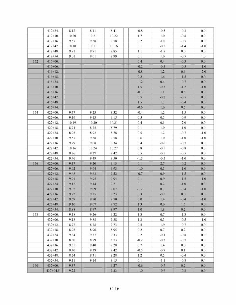
C-16
412+24. 8.12 8.11 8.41 -0.8 -0.5 -0.3 0.0 412+30. 10.20 10.21 10.22 1.7 1.0 -0.8 0.0 412+36. 9.57 9.58 9.58 0.2 -1.0 -0.5 0.0 412+42. 10.10 10.11 10.16 0.1 -0.5 -1.4 -1.0 412+48. 9.91 9.91 9.85 1.1 -1.8 0.0 0.0 412+54. 9.01 9.01 8.99 0.1 1.0 -0.5 1.0
152 416+00. 0.4 0.4 -0.3 0.0 416+06. -0.2 -0.5 -0.5 -1.0 416+12. -0.8 1.2 0.6 -2.0 416+18. 0.2 1.6 -1.5 0.0 416+24. -1.2 0.4 -0.7 0.0 416+30. 1.5 -0.3 -1.2 -1.0 416+36. -0.3 1.1 0.8 0.0 416+42. 0.5 -0.2 -0.5 0.0 416+48. 1.5 1.3 -0.4 0.0 416+54. -0.6 1.0 0.5 0.0
154 422+00. 9.37 9.23 9.32 -0.4 1.2 -1.5 0.0 422+06. 9.19 9.13 9.15 0.5 0.5 -0.9 0.0 422+12. 10.19 10.20 10.31 0.4 0.1 -2.0 0.0 422+18. 8.74 8.75 8.79 0.1 1.0 -1.0 0.0 422+24. 8.93 8.92 8.78 0.5 1.2 -0.7 -1.0 422+30. 9.57 9.58 9.58 0.6 1.0 -1.0 -1.0 422+36. 9.29 9.08 9.34 0.4 -0.6 -0.7 0.0 422+42. 10.16 10.24 10.27 0.8 -0.5 -0.8 0.0 422+48. 9.26 9.27 9.42 0.5 -0.5 -0.5 0.0 422+54. 9.46 9.49 9.50 -1.3 -0.5 -1.0 0.0
156 427+00. 9.17 9.20 9.13 0.1 2.7 -0.2 0.0 427+06. 9.92 9.94 9.93 -1.0 0.5 -1.0 0.0 427+12. 9.68 9.63 9.52 -0.7 0.9 -1.5 0.0 427+18. 9.91 9.95 9.94 0.1 0.9 -1.5 -1.0 427+24. 9.12 9.14 9.21 0.1 0.2 -1.0 0.0 427+30. 9.02 9.09 9.07 -1.2 0.7 -0.4 -1.0 427+36. 9.22 9.25 9.23 0.3 -0.5 0.0 0.0 427+42. 9.69 9.70 9.70 0.0 1.4 -0.4 -1.0 427+48. 9.10 9.07 9.72 1.3 0.0 1.5 0.0 427+54. 8.88 8.97 8.97 1.0 1.8 0.2 0.0
158 432+00. 9.18 9.26 9.22 1.3 0.7 -1.3 0.0 432+06. 9.18 9.88 9.88 1.3 0.3 -0.5 -1.0 432+12. 8.72 8.78 9.73 0.5 1.9 -0.7 0.0 432+18. 8.93 8.96 8.95 0.2 0.7 0.2 0.0 432+24. 9.34 9.37 9.33 0.2 -0.1 -0.8 0.0 432+30. 8.80 8.79 8.73 -0.2 -0.3 -0.7 0.0 432+36. 9.35 9.40 9.28 0.7 1.4 0.0 0.0 432+42. 9.40 9.39 9.42 -0.5 -0.7 0.1 0.0 432+48. 8.24 8.31 8.28 1.2 0.5 -0.4 0.0 432+54. 9.11 9.14 9.15 0.1 -1.1 -0.8 0.4
160 437+00. 9.37 9.27 -0.6 -0.7 0.2 0.0 437+04.5 9.22 9.33 -1.0 -0.6 -0.8 0.0

C-17
437+09. 9.45 9.45 0.0 -0.9 0.4 -1.0 437+13.5 9.04 9.10 -0.3 -1.3 -0.5 -1.0 437+18. 9.18 9.12 0.2 0.3 -1.6 0.0 437+22.5 9.74 9.86 0.1 -0.3 0.2 0.0 437+27. 8.69 8.67 0.5 -0.5 -0.3 -1.0 437+31.5 9.36 9.38 1.0 0.0 -1.0 -1.0 437+36. 9.48 9.50 0.6 -1.3 -0.2 0.0 437+40.5 9.94 9.67 -0.3 -0.1 -0.5 -1.0
162 442+00. 9.19 9.12 9.13 1.5 0.6 0.4 0.0 442+04.5 9.61 9.61 9.49 0.4 0.0 -0.4 0.0 442+09. 9.23 9.21 9.19 1.1 -0.1 -0.8 0.0 442+13.5 9.44 9.52 9.38 1.3 -1.5 -0.4 -1.0 442+18. 8.45 8.44 8.48 1.2 -0.8 0.0 0.0 442+22.5 9.13 9.15 9.15 -0.6 -0.2 0.0 0.0 442+27. 9.41 9.45 9.36 0.2 0.1 0.0 0.0 442+31.5 9.53 9.46 9.44 1.3 -0.4 -0.7 0.0 442+36. 9.95 9.89 9.74 -0.3 0.6 -0.8 0.0 442+40.5 9.36 9.43 9.32 0.5 0.6 -0.5 0.0
164 447+00. 9.32 9.40 9.35 0.7 -0.3 -1.3 0.0 447+06. 10.08 10.15 9.97 -0.3 -2.2 -1.3 0.0 447+12. 9.75 9.81 9.82 -1.3 0.2 -1.7 0.0 447+18. 10.07 10.02 10.05 -1.0 -1.3 -1.0 0.0 447+24. 8.63 8.61 8.61 0.3 -0.2 0.2 0.0 447+30. 9.46 9.46 9.57 -0.5 0.7 -0.5 0.0 447+36. 9.57 9.54 9.54 -0.5 1.1 -0.3 0.0 447+42. 8.13 8.16 8.23 0.9 1.0 -2.0 0.0 447+48. 9.91 9.91 9.95 1.3 -0.7 -0.3 -1.0 447+54. 10.06 10.06 10.08 -0.2 0.0 -1.1 -1.0
166 452+00. 9.22 9.20 9.16 0.5 -0.4 0.0 0.0 452+06. 8.96 8.96 9.05 -0.7 -0.4 -0.5 0.0 452+12. 9.97 10.00 10.04 -0.1 -0.6 -1.5 -1.0 452+18. 9.11 9.07 9.20 -0.4 -0.9 -0.4 0.0 452+24. 9.07 8.94 9.06 0.0 0.7 -0.6 0.0 452+30. 8.39 8.35 8.41 -2.9 -0.8 -1.3 0.0 452+36. 8.54 8.52 8.52 0.2 0.7 0.2 0.0 452+42. 8.03 8.01 8.09 0.2 1.0 0.5 -1.0 452+48. 9.06 9.09 9.13 0.9 -0.2 0.3 1.0 452+54. 9.66 9.66 9.57 1.7 1.5 -0.3 -1.0
170 461+50. 9.72 9.64 9.69 0.7 -1.3 0.0 0.0 461+54.5 9.14 9.05 9.08 0.4 -0.5 -2.7 0.0 461+59. 10.24 10.16 10.02 -0.4 -0.2 -0.3 0.0 461+63.5 9.94 9.98 10.05 1.1 0.2 0.2 0.0 461+68. 10.28 10.21 10.15 0.6 0.5 0.7 -1.0 461+72.5 9.16 9.15 9.29 0.5 0.0 -1.1 0.0 461+77. 8.93 8.92 9.05 -0.6 0.4 -0.2 -1.0 461+81.5 9.33 9.37 9.36 -0.3 0.8 -0.2 -1.0 461+86 8.90 8.90 8.75 0.4 -0.6 -1.7 0.0 461+90.5 10.11 10.13 9.98 -0.3 1.8 0.5 0.0

C-18
172 466+00. 9.92 9.91 9.84 -1.0 1.2 0.2 0.0 466+06. 10.30 10.29 10.28 0.0 0.4 -0.9 0.0 466+12. 10.04 10.07 10.11 -0.4 -0.8 0.4 0.0 466+18. 8.58 8.54 8.57 -0.2 -1.1 -0.3 0.0 466+24. 10.19 10.20 10.27 0.2 -0.2 -0.3 0.0 466+30. 9.21 9.18 9.17 1.2 -2.3 -0.5 -2.0 466+36. 9.74 9.74 9.61 -0.6 -0.5 -1.1 0.0 466+42. 9.07 9.02 9.13 -0.2 -0.3 -0.3 0.0 466+48. 9.15 9.11 8.97 0.7 -0.5 0.1 0.0 466+54. 9.81 9.80 9.81 -1.2 -1.5 -1.4 -1.0
174 470+50. 9.64 9.59 9.49 0.0 0.4 -0.6 0.0 470+56. 8.63 8.63 8.64 0.3 -0.3 -1.3 0.0 470+62. 10.06 10.04 10.04 0.6 0.0 -1.4 0.0 470+68. 9.00 8.98 9.03 0.7 -0.5 -0.8 0.0 470+74. 8.91 8.86 8.88 -0.8 -0.4 -0.7 0.0 470+80. 9.95 9.93 9.95 0.8 -0.3 -1.0 0.0 470+86 8.99 8.97 8.95 -1.1 0.3 -2.0 0.0 470+92. 9.87 9.72 9.87 -0.5 0.6 -0.3 0.0 470+98. 9.58 9.53 9.48 -0.1 0.5 -0.7 0.0 471+04. 9.45 9.50 9.32 1.2 -0.6 -1.5 0.0
176 475+00. 9.65 9.59 9.65 -0.8 -1.6 -0.8 0.0 475+04.5 9.83 9.86 9.92 1.6 -1.0 0.0 0.0 475+09. 9.26 9.22 9.23 0.1 -0.2 -0.5 -1.0 475+13.5 9.14 9.18 9.22 -0.3 0.2 -0.9 0.0 475+18. 8.87 8.75 8.79 0.3 -0.3 -0.8 0.0 475+22.5 9.35 9.32 9.37 0.4 -0.3 -0.9 -1.0 475+27. 8.33 8.37 8.26 0.8 -0.1 0.0 0.0 475+31.5 - - - 0.7 0.1 0.0 0.0 475+36. 9.14 9.19 9.73 -0.6 0.2 -1.8 0.0 475+40.5 9.66 9.62 9.43 0.0 -0.5 0.7 0.0
178 479+50. 9.57 9.58 9.69 0.3 -0.3 0.5 0.0 479+54.5 9.47 9.53 9.55 -0.4 -0.4 -0.7 0.0 479+59. 8.67 8.62 8.62 -0.2 0.0 -0.5 -1.0 479+63.5 9.26 9.26 9.28 0.6 1.2 -0.2 0.0 479+68. 9.85 9.80 9.77 0.0 0.2 -1.8 0.0 479+72.5 9.87 9.92 9.95 -1.4 -0.4 -0.6 0.0 479+77. 11.15 11.13 11.02 -1.0 23.0 -0.3 0.0 479+81.5 9.20 9.23 9.19 -0.3 0.0 -0.9 0.0 479+86. 8.82 8.79 8.72 -0.8 -2.0 -0.6 0.0 479+90.5 9.30 9.29 9.30 -0.3 -0.3 -0.2 0.0
180 484+00. 8.93 8.88 8.99 -0.5 0.5 0.4 0.0 484+06. 9.08 9.06 8.82 1.4 2.0 -1.0 0.0 484+12. 9.81 9.80 9.76 -0.5 0.8 -0.1 0.0 484+18. 9.69 9.69 9.69 0.7 1.3 -1.2 0.0 484+24. 9.71 9.69 9.54 0.9 0.1 -0.8 0.0 484+30. 9.87 9.77 9.98 1.8 0.2 -1.0 0.0 484+36. 8.88 8.88 8.74 0.0 -0.5 -0.5 0.0 484+42. 9.57 9.53 9.42 -1.3 0.8 -1.1 -1.0

C-19
484+48. 9.34 9.37 9.38 -0.7 0.4 -1.8 0.0 484+54. 9.65 9.66 9.44 -0.5 1.0 -1.0 0.0
182 488+50. 9.34 9.40 9.34 0.4 0.1 -1.6 0.0 488+56. 8.49 8.49 8.46 -0.3 0.2 -1.2 -1.0 488+62. 10.43 10.48 10.14 0.2 0.2 -1.5 0.0 488+68. 9.51 9.47 9.64 -1.9 1.0 -1.3 0.0 488+74. 9.72 9.77 9.73 1.8 0.2 -0.8 -1.0 488+80. 9.01 8.97 8.97 -1.8 0.5 0.5 0.0 488+86. 9.50 9.52 9.54 -0.8 0.8 0.1 0.0 488+92. 9.65 9.57 9.52 0.5 0.5 0.1 -1.0 488+98. 9.40 9.33 9.35 0.1 0.2 0.3 0.0 489+04. 9.95 10.01 9.82 0.3 0.0 -0.2 -1.0
184 493+00. 8.97 8.97 8.89 0.5 0.9 -0.5 0.0 493+09. 8.42 8.59 8.48 0.1 0.5 -1.4 0.0 493+18. 9.29 9.20 9.21 0.6 -0.9 -1.7 0.0 493+27. 10.62 10.63 10.52 0.3 1.4 0.0 -1.0 493+36. 9.38 9.45 9.41 -0.5 0.5 0.0 -1.0 493+45. 9.67 9.66 9.56 -0.8 1.3 0.7 0.0 493+54. 9.55 9.50 9.54 1.3 0.7 0.0 0.0 493+63. 9.65 9.59 9.58 1.5 1.0 0.1 -2.0 493+72. 9.05 9.10 9.12 0.3 0.4 0.2 -1.0 493+81. 9.57 9.45 9.45 -0.1 0.7 0.2 -1.0
186 497+50. 9.06 9.11 9.00 1.0 -0.5 -0.2 -1.0 497+59. 8.56 8.64 8.53 -0.4 -0.9 -1.0 0.0 497+68. 8.84 8.81 8.81 0.5 1.0 -0.7 0.0 497+77. 9.46 9.43 9.49 -0.4 0.2 -0.7 0.0 497+86. 10.13 10.07 10.09 -0.7 0.5 0.5 0.0 497+95. 9.58 9.50 9.56 0.1 0.6 -1.3 0.0 498+04. 10.08 10.10 10.07 -0.5 0.5 1.0 0.0 498+13. 9.83 9.84 9.74 -0.8 0.7 -0.1 0.0 498+22. 10.85 10.75 10.71 0.0 1.3 -0.8 0.0 498+31. 9.87 9.91 9.87 -1.2 0.0 -1.3 0.0
189 504+50. 9.47 9.44 9.41 0.3 -1.0 -0.3 0.0 504+54.5 9.40 9.39 9.38 0.6 1.2 0.2 0.0 504+59. 9.94 9.92 9.78 -0.8 -0.1 -0.8 0.0 504+63.5 9.69 9.65 9.56 -1.6 -1.5 -0.5 0.0 504+68. 9.87 9.79 9.86 0.0 0.0 -2.2 0.0 504+72.5 9.01 8.97 8.88 -0.1 -0.7 0.5 0.0 504+77. 8.86 8.92 8.89 -0.2 0.7 -0.8 0.0 504+81.5 9.59 9.47 9.45 0.2 -0.2 0.0 -1.0 504+86. 9.16 9.14 8.91 1.2 0.1 -1.0 -1.0 504+90.5 9.04 9.11 9.00 0.0 1.2 -0.8 0.0
191 510+50. 9.43 9.47 9.34 0.3 0.4 -0.6 -1.0 510+56. 9.90 9.89 9.97 -0.1 0.3 -0.5 -1.0 510+62. 10.17 10.13 9.99 0.7 -0.2 -0.5 0.0 510+68. 8.96 9.01 8.96 0.2 0.3 0.0 -1.0 510+74. 9.26 9.24 9.23 0.7 0.5 -0.1 0.0 510+80. 9.22 9.23 9.12 -0.4 -1.0 -0.6 0.0

C-20
510+86. 9.81 9.88 9.68 -1.0 -1.1 -1.0 0.0 510+92. 9.59 9.59 9.57 1.5 -0.3 -0.8 -1.0 510+98. 8.70 8.65 8.54 -1.8 0.1 -0.3 0.0 511+04. 9.20 9.17 9.14 0.5 -0.5 -0.4 0.0

APPENDIX D:
CROSS SECTIONAL STRUCTURAL ANALYSIS

D-1
CROSS SECTIONAL STRUCTURAL ANALYSIS DESCRIPTION OF THE COMPOSITE PAVEMENT The cross section of the pavement on IA 13 is as shown in Figure D.1. The bottom portland cement concrete (PCC) layer consists of a thickened edge section that is 18 feet wide. This layer is 10 inches deep at each edge and 7 inches deep at the centerline and 40+ years old. Later this section was overlaid to a depth of 5 inches with asphalt cement concrete (ACC) over time during the 1970–1990s. During the summer of 2001, this overlaid and widened as shown in the figure with PCC. This consisted of 5-foot-wide by 8-inch-deep widening unit sections and an overlay of 3.5 inches of PCC in half the length of the project (9.2 miles) and 4.5 inches of PCC depth in the other half. Three different surface preparations (milling, patching, and ACC bond breaker) were used to prepare the ACC surface for the overlay and potential bonding. The PCC overlay and widening includes sections with three types of fiber reinforcement and some without reinforcement. In addition, there are three joint patterns on the PCC surface over the original pavement ACC overlay area. The 18-foot width is divided into 4.5-foot squares, 6-foot squares, or 9-foot squares. Furthermore, deformed reinforcing bars were added at the interface between the old and the concrete along the edges on some specific test sections. The pavement is provided with a two percent crown. OBJECTIVE
The general profile of the cross section of the composite pavement shown in Figure D.1 appears to have a crown that could be considered to development of arch action. In this case, one can infer that the arch action, along with the confinement provided by the two concrete widening units along the edges of the original pavement result in reducing the loads transmitted to the original ACC and the PCC pavement sublayers. This conclusion seems to agree with basic structures behavior; however, more justification is needed to reinforce such a conclusion. The objective of this study was to develop analytical model(s) that can provide insight into the potential stress reduction in the two sublayers beneath the top PCC layer due to the arch action and the lateral confinement. In addition, a parametric study was conducted to investigate the factors that may affect, and ultimately improve the overall structural behavior of this type of composite pavement.

D-2
(c) Cross Section View – Pavement 2
Figure D.1. Schematics of the Composite Pavement (Not to Scale)
9’ 9’
9’ 9’ 9’
4.5’ 4.5’ 4.5’ 4.5’5’ 5’
6’
6’
6’ 6’
(a) Plan View
4.5’ 4.5’
6’ 6’
Sawed joints (1.5 “ deep) Joint formed not sawed (1.0 “ deep)
5’. 9’ 5’
5”
7”
5”
PCC
ACCACC
Concrete Lug
Concrete Lug
10”
9’ 9’
5” 7”
5”
(b) Cross Section View – Pavement 1
PCC
ACCACC
10”
3.5
8”
9’
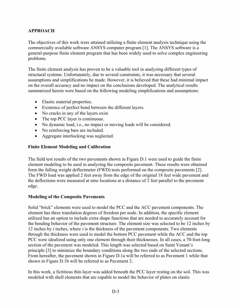
D-3
APPROACH The objectives of this work were attained utilizing a finite element analysis technique using the commercially available software ANSYS computer program [1]. The ANSYS software is a general-purpose finite element program that has been widely used to solve complex engineering problems. The finite element analysis has proven to be a valuable tool in analyzing different types of structural systems. Unfortunately, due to several constraints, it was necessary that several assumptions and simplifications be made. However, it is believed that these had minimal impact on the overall accuracy and no impact on the conclusions developed. The analytical results summarized herein were based on the following modeling simplifications and assumptions:
• Elastic material properties. • Existence of perfect bond between the different layers. • No cracks in any of the layers exist. • The top PCC layer is continuous. • No dynamic load, i.e., no impact or moving loads will be considered. • No reinforcing bars are included. • Aggregate interlocking was neglected.
Finite Element Modeling and Calibration
The field test results of the two pavements shown in Figure D.1 were used to guide the finite element modeling to be used in analyzing the composite pavement. These results were obtained form the falling weight deflectmeter (FWD) tests performed on the composite pavements [2]. The FWD load was applied 2 feet away from the edge of the original 18 feet wide pavement and the deflections were measured at nine locations at a distance of 2 feet parallel to the pavement edge. Modeling of the Composite Pavements Solid “brick” elements were used to model the PCC and the ACC pavement components. The element has three translation degrees of freedom per node. In addition, the specific element utilized has an option to include extra shape functions that are needed to accurately account for the bending behavior of the pavement structure. The element size was selected to be 12 inches by 12 inches by t inches, where t is the thickness of the pavement components. Two elements through the thickness were used to model the bottom PCC pavement while the ACC and the top PCC were idealized using only one element through their thicknesses. In all cases, a 70-foot-long section of the pavement was modeled. This length was selected based on Saint Venant’s principle [3] to minimize the boundary conditions along the two ends of the selected sections. From hereafter, the pavement shown in Figure D.1a will be referred to as Pavement 1 while that shown in Figure D.1b will be referred to as Pavement 2. In this work, a fictitious thin layer was added beneath the PCC layer resting on the soil. This was modeled with shell elements that are capable to model the behavior of plates on elastic

D-4
foundation. Different soil sub-grade reactions ranging from 100 pci to 150 pci were investigated. This was considered since no FWD test results were performed on the soil at the pavement site. Similar shell elements were also added along the two sides of the 5-foot-widened section to investigate the effects of the confinement provided by soil along the side of the road. A crack depth (joint) of one inch was considered along the two edges between the original and the widened pavement. Compression only springs were added to connect the middle part of the pavement and the 5-foot-widened sections. This type of element requires that an iterative solution be utilized until a converged solution is reached. The finite element idealization of Pavements 1 and 2 are shown in Figures D.2 and D.3, respectively. The finite element model of Pavement 1 consisted of 6,580 elements and 9,017 nodes, while 11,482 elements and 12,283 nodes were utilized in the idealization of Pavement 2.
Figure D.2. Isometric View of Pavement 1 Finite Element Model

D-5
Figure D.3. Isometric View of Pavement 2 FINITE ELEMENT MODEL VS. FIELD TEST RESULTS Figures D.4 and D.5 summarize the deflection results induced in the two pavement structures in the vicinity of the applied load considering different soil sub-grade reactions. Shown in Figure D.6 is a summary of the finite element results considering Pavement 1, Pavement 2, and without the two 5-foot-widened sections. These results were included here in to illustrate the effects of the two widening units on the deflection in Pavement 2. The solutions were carried out using different soil subgrade reactions.

D-6
-0.009
-0.008
-0.007
-0.006
-0.005
-0.004
-0.003
-0.002
-0.001
0.000
-20 -10 0 10 20 30 40 50 60 Location (in.)
( 0.0 in. = Under the applied load)
Def
lect
ion-
in.
Field Test F.E. (Ks =150 psi)F. E. (Ks=125 psi)F.E. ( Ks=100 psi)
-0.00400
-0.00350
-0.00300
-0.00250
-0.00200
-0.00150
-0.00100
-0.00050
0.00000
-20 -10 0 10 20 30 40 50 60Location-in.
(0.0 in. = under the applied load)
Def
lect
ion-
in.
Field TestF.E. ( Ks=150 psi)F.E. ( Ks=125 psi)F.E. ( Ks=100 psi)
Figure D.4. Comparison between Field and Analytical Results for Pavement 1 (FWD Applied Near Edge)
Figure D.5. Comparison between Field and Analytical Results for Pavement 2 (FWD Applied Near Edge)

D-7
-0.008
-0.007
-0.006
-0.005
-0.004
-0.003
-0.002
-0.001
0.000
-20 -10 0 10 20 30 40 50 60 Location (in.)
( 0.0 in. = Under the applied load)
Def
lect
ion
(in.)
pavement 1pavement 2 without widening sectionspavement 2
Figure D.6. Comparison between Field and Analytical Results for Pavement 2 without the Two Widening Units (FWD Applied Near the Edge)
As can be seen, the deflection distribution obtained from the finite element analyses generally follows the deflection profile of the field test. The slight discrepancy between the test and theoretical results can be attributed to the fact that the actual pavement material properties were not known, and/or not including the presence of cracks that may have existed in the pavement. However, since the differences were generally small, it was concluded that the utilized finite element models could accurately predict the deflections in the composite pavement. Effects of the Two Widening Units
Comparing the results in Figure D.6 reveals that the addition of the two lugs reduced the deflection from 0.00765 to 0.00347 inches. On the other hand, the results summarized in Figure D.6 includes only the top PCC layer and excludes the two widening units reducing the maximum deflection from 0.00765 to 0.00492 inches. This illustrates that the two widening units provide confinement to the arch action due to the presence of the two percent crown resulting in reducing the deflection in the composite pavement.

D-8
Analysis of the Composite Pavements under Truck Loading
The two pavements illustrated in Figures D.1a and D.1b were analyzed considering the load illustrated in Figure D.7. Axel loads were applied as pressures on the elements that correspond to the tire locations. These pressures were calculated based on the load per tire and the area of element, i.e., 12 inches by 12 inches. The effects of the soil modulus, the crown, and the depth of the crack (joint) along the edges of the top PCC pavement were investigated.
Figure D.7. Configuration of Truckload Used in Analysis Deflection Results The two composite pavements were analyzed considering soil modulus of 75 and 150 pci, which were selected to represent two different seasons, i.e., spring and fall, respectively. In addition, a crack (joint) depth of one inch along the two edges of the original pavement was considered. Table D.1 summarizes the predicted maximum deflections in Pavements 1 and 2. The different layers of the pavement are listed from top to bottom, i.e., in the following order: top PCC, ACC, and the PCC resting on the soil. The overall deflected shapes of the two pavements are shown in Figures D.8 and D.9, respectively. Notice that the maximum deflection is localized and occurs in the vicinity of the applied duel load near the pavement edge.
92.5”
8k 16k 16k 21k 20k
12′ 3′ 15′ 15′
70.3”
Axel Load

D-9
Minimum Maximum Note: Negative sign indicates downward deflection.
Figure D.8. Deformed Shape of Pavement 1 under Truckload Shown in Figure D.7 (Deflection Is Magnified)

D-10
Note: Negative sign indicates downward deflection.
Figure D.9. Deformed Shape of Pavement 2 under Truckload Shown in Figure D.7 (Deflection Is Magnified)
Table D.1. Maximum Deflections in the Composite Pavements
Soil Subgrade = 75 pci Soil Subgrade = 150 pci Crown = 2% Crown = 3% Crown = 2% Crown = 3%
(2) Pavement 1
(3) 0.0325
(4) 0.03240
(5) 0.0195
(6) 0.0194
(1) Deflection (inches) Pavement 2 0.0128 0.01279 0.0080 0.0078
Note: ( ) = column number. Examining the results in Table D.1 reveals that increasing the crown from two percent to three percent resulted in an insignificant reduction in the deflection (compare columns 3 and 4 or columns 5 and 6 of Table D.1). Also, comparing columns 3 and 5 or 4 and 6 of Table D.1 demonstrates that a reduction of 40 percent was reached as the soil modulus was doubled. In addition, the results in Table D.1 show that the deflection in the composite pavement was
Minimum Maximum
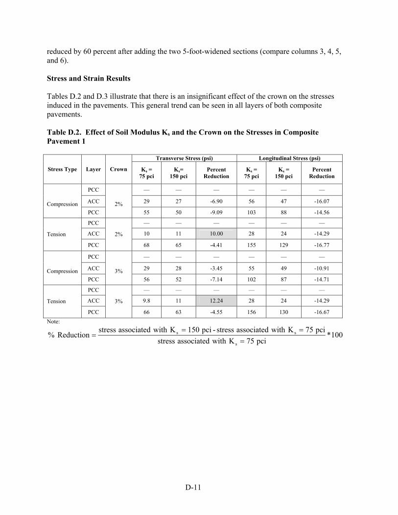
D-11
reduced by 60 percent after adding the two 5-foot-widened sections (compare columns 3, 4, 5, and 6). Stress and Strain Results Tables D.2 and D.3 illustrate that there is an insignificant effect of the crown on the stresses induced in the pavements. This general trend can be seen in all layers of both composite pavements. Table D.2. Effect of Soil Modulus Ks and the Crown on the Stresses in Composite Pavement 1
Transverse Stress (psi) Longitudinal Stress (psi)
Stress Type Layer Crown Ks = 75 pci
Ks= 150 pci
Percent Reduction
Ks = 75 pci
Ks = 150 pci
Percent Reduction
PCC — — — — — —
ACC 29 27 -6.90 56 47 -16.07 Compression PCC
2%
55 50 -9.09 103 88 -14.56
PCC — — — — — —
ACC 10 11 10.00 28 24 -14.29 Tension
PCC
2%
68 65 -4.41 155 129 -16.77
PCC — — — — — —
ACC 29 28 -3.45 55 49 -10.91 Compression PCC
3%
56 52 -7.14 102 87 -14.71
PCC — — — — — —
ACC 9.8 11 12.24 28 24 -14.29 Tension
PCC
3%
66 63 -4.55 156 130 -16.67 Note:
100*pci75Kwithassociatedstress
pci75Kwithassociatedstress-pci150KwithassociatedstressReduction %
s
ss
===
=

D-12
Table D.3. Effect of Soil Modulus Ks on the Stress in Composite Pavement 2
Transverse Stress (psi) Longitudinal Stress (psi)
Stress Type Layer Crown Ks = 75 pci
Ks= 150 pci
Percent Reduction
Ks = 75 pci
Ks = 150 pci
Percent Reduction
PCC 103 92 -10.68 73 64 -12.33
ACC 23 23 0.00 9.6 8.5 -11.46 Compression PCC
2%
8.5 8 -5.88 51 32 -37.25
PCC 15 15 0.00 65 40 -38.46
ACC 16 14 -12.50 9 5.5 -38.89 Tension
PCC
2%
74 66 -10.81 78 68 -12.82
PCC 101 91 -9.90 73 64 -12.33
ACC 23 22 -4.35 9.5 8.5 -10.53 Compression PCC
3%
10 9 -10.00 49 31 -36.73
PCC 13 14 7.69 66 41 -37.88
ACC 15 13.7 -8.67 9 6 -33.33 Tension
PCC
3%
73 66 -9.59 79 69 -12.66 Note:
100*pci75Kwithassociatedstress
pci75Kwithassociatedstress-pci150KwithassociatedstressReduction %
s
ss
===
=
Tables D.2 and D.3 also show that in most cases, increasing the soil subgrade modulus resulted in reducing the stress in the transverse and longitudinal directions. These tables also show that there were slight increases in (about 12 percent) the stress in the transverse direction in the ACC pavement (see the shaded cells in Tables D.2 and D.3) as the sub-grade modulus was increased from 75 pci to 150 pci. This increase is insignificant since these values were very small compared to the typical pavement material compressive strengths. The induced strains in Pavements 1 and 2 when subject to the truckload are summarized in Tables D.4 and D.5. Notice that the maximum tabulated compressive strain value is 72 microstrains and occurred in the ACC layer of Pavement 1. Table D.4 also illustrates that the maximum induced tensile strain was 50 microstrains and occurred in the bottom layer of Pavement 1. The maximum compressive and tensile strains induced in Pavement 2 were 29 and 25 microstrains, respectively.

D-13
Table D.4. Effect of Soil Modulus Ks and the Crown on Strains in Composite Pavement 1 Transverse Strain (µε) Longitudinal Strain (µε)
Stress Type Layer Crown Ks = 75 pci
Ks= 150 pci
Percent Reduction
Ks = 75 pci
Ks = 150 pci
Percent Reduction
PCC — — — — — —
ACC 31 30 -3.23 72 61 -15.28 Compression
PCC
2%
13.5 13.4 -0.74 33 27 -18.18
PCC — — — — — —
ACC 18 18.8 4.44 37 32 -13.51 Tension PCC
2% 16.5 16.1 -2.42 50 42 -16.00
PCC — — — — — —
ACC 32 30 -6.25 72 61 -15.28 Compression
PCC
3%
14 13.5 -3.57 32 27 -15.63
PCC — — — — — —
ACC 18 18 0.00 37 32 -13.51 Tension PCC
3% 16 16 0.00 50 42 -16.00
Note:
100*pci75Kwithassociatedstrain
pci75Kwithassociatedstrain-pci150KwithassociatedstrainReduction %
s
ss
===
=
Table D.5. Effect of Soil Modulus Ks and the Crown on Strains in Composite Pavement 2 Transverse Strain (µε) Longitudinal Strain (µε)
Stress Type Layer Crown Ks = 75 pci
Ks= 150 pci
Percent Reduction
Ks = 75 pci
Ks = 150 pci
Percent Reduction
PCC 27 24 -11.11 19.7 17. -13.71
ACC 29 28 -3.45 10.3 9.0 -12.62 Compression PCC
2%
4 3.5 -12.50 16.5 10.3 -37.58
PCC 8 7.8 -2.50 21 13 -38.10
ACC 22 19.6 -10.91 11.6 7.2 -37.93 Tension
PCC
2%
21.5 19.0 -11.63 25 21.9 -12.40
PCC 26.5 23 -13.21 19.6 17.0 -13.27
ACC 27.8 27 -2.88 10.3 9.0 -12.62 Compression PCC
3%
4.1 3.5 -14.63 16 10 -37.50
PCC 7.4 7.2 -2.70 21.4 13.3 -37.85
ACC 21.4 19 -11.21 12.1 7.5 -38.02 Tension
PCC
3%
21.4 19 -11.21 25.3 22 -13.04 Note:
100*pci75Kwithassociatedstrain
pci75Kwithassociatedstrain-pci150KwithassociatedstrainReduction %
s
ss
===
=

D-14
Summarized in Tables D.6 and D.7 are the stresses in Pavement 1 and 2 considering two soils with different modules of elasticity. As can be noticed, there was a significant decrease in the longitudinal stresses induced in Pavement 2 when compared to similar stresses in Pavement 1. Including the two 5 feet widening sections results in reducing these stresses in each layer of the composite pavement. Similar observations can also be noticed when comparing the compressive stresses in the transverse direction. However, one may also notice that adding the two 5-foot-widened sections results in increasing the tensile stress in the transverse direction. The shaded cells in Tables D.6 and D.7 designate these locations. Table D.6. Comparison between the Stresses in Pavements 1 and 2 (Ks = 75 pci)
Transverse Stress (psi) Longitudinal Stress (psi)
Pavement Pavement Stress Type Layer
Crown
(1) (2) Percent
Difference (1) (2) Percent
Difference
PCC — 103 N/A — 73 N/A
ACC 29 23 -20.69 56 9.6 -82.86 Compression PCC
2%
55 8.5 -84.55 103 51 -50.49
PCC — 15 N/A — 65 N/A
ACC 10 16 60.00 28 9.0 -67.86 Tension
PCC
2%
68 74 8.82 155 78 -49.68
PCC — 101 N/A — 73 N/A
ACC 29 23 -20.69 55 9.5 -82.73 Compression PCC
3%
56 10 -82.14 102 49 -51.96
PCC — 13 N/A — 66 N/A
ACC 9.8 15 53.06 28 9.0 -67.86 Tension
PCC
3%
66 73 10.61 156 79 -49.36 Note: % Difference = (stress in Pavement 2 - stress in Pavement 1) / (stress in Pavement 1)

D-15
Table 7. Comparison between the Stresses in Pavements 1 and 2 (Ks = 150 pci)
Transverse Stresses (psi) Longitudinal Stresses (psi) Pavement Pavement Stress Type
Layer
Crown (1) (2)
Percent Difference (1) (2)
Percent Difference
PCC — 92 N/A — 64 N/A
ACC 27 23 -14.81 56 8.5 -84.82 Compression
PCC
2%
50 8 -84.00 103 32 -68.93
PCC — 15 N/A — 40 N/A
ACC 11 14 27.27 28 5.5 -80.36 Tension PCC
2%
65 66 1.54 155 68 -56.13
PCC — 91 N/A — 64 N/A
ACC 28 22 -21.43 55 8.5 -84.55
Compression
PCC
3%
52 9 -82.69 102 31 -69.61
PCC — 13.7 N/A — 41 N/A
ACC 11 13.7 24.55 28 6 -78.57
Tension
PCC
3%
63 66 4.76 156 69 -55.77
Note: % Difference = (stress in Pavement 2 - stress in Pavement 1) / (stress in Pavement 1) The above listed observations can be attributed to the structural behavior of the widened pavement. In general, the composite pavement behaves as a shallow shell structure supported on a elastic foundation. In the longitudinal direction, the structure follows beam theory. In this case, adding the top PCC and the two widened sections increase the overall section flexural rigidity. This results in reducing the longitudinal stresses. On the other hand, the effects of adding these two components on the induced transverse stress can be explained as follows. Figure D.10 illustrates the forces acting on s cross section of the composite pavement. As can be seen, the confinement force, F, provides a compression force in the transverse direction as well as a moment, M (see Figure D.10). Utilizing the principles of mechanics of material, the combination of these two forces would result in an increase in compressive and tensile stresses in the area of the pavement above and below the neutral axis, respectively.

D-16
Concrete Lug
PC
ACCACC
Concrete Lug
F e
A
A
M=F.e
Sec. A-A
PC
PCAC Centerline of pavement (location
varies with overall depth)
LC of pavement
Figure D.10. Schematic Showing Forces Acting on Composite Pavement, Effect of Crack (Joint) Depth
The pavement in Figure D.1c was reanalyzed to investigate the effects of the crack depth along the edges of the top PCC pavement on the structural behavior of the composite pavement. Two different crack depths of one and two inches were considered, and the results of these analyses are summarized in Table D.8. The results demonstrated that there was an increase of 35 percent and 67 percent in the transverse and the longitudinal stresses, respectively, and in the ACC pavement when the crack depth was doubled. In addition, the compression and tension stresses induced in the top PCC layer were reduced as the crack depth was increased. This is due to the fact that this layer is acting as a free plate supported on a rigid foundation that is provided by the ACC and the Bottom PCC layers. Table D.8 also illustrates that there were insignificant changes in the stresses in the other layers of the composite pavement. Table D.8. Effect of Crack (Joint) Depth on the Stress in Composite Pavement 2 (Ks = 75 pci and Crown = 2%)
Transverse Stresses (psi) Longitudinal Stress (psi) Crack Depth Crack Depth Stress Type Layer
1 inch 2 inches Percent Change 1 inch 2 inches
Percent Change
PCC 103 93 -9.71 73 71 -2.74 ACC 23 31 34.78 9.6 16 66.67
Compression PCC 8.5 8.0 -5.88 51 52 1.96 PCC 15 9.1 -39.33 65 65 0.00 ACC 16 17 6.25 9 9.5 5.56 Tension PCC 74 77 4.05 78 79 1.28
Note:

D-17
100in. 1depth crack a with associated stress
in.] 1depth crack a with associated stress- in. 2depth crack a with associated [stress Change % x=
SUMMARY, CONCLUSIONS, AND RECOMMENDATIONS Two types of composite pavements subjected to a truckload were analyzed utilizing static and elastic finite element idealizations. The analyses considered the effects of the soil subgrade reaction, the crown and other parameters on the overall structural behavior of the pavements. The results illustrated that adding two widening sections and a PCC overlay resulted in significant reduction in the deflection and the stresses in the original composite pavement. This was due to the increase in the flexural rigidity of the pavement section and the presence of the arch action along with the confinement force provided by the two widening sections. Future work should account for the non-linear behavior of the different components of the pavement material. The effect of the cracks, bond, and aggregate interlocking should be addressed in the future since these may have dominated effects on the structural behavior of this type of pavement. REFERENCES 1. ANSYS, Inc. ANSYS Finite Element Program. ANSYS Inc., Canonsburg, Pennsylvania.
2. “IA 13, Delaware County, Pre- and Post-Overlay Test Results,” personal correspondence
from J.K. Cable to F.S. Fanous, January 23, 2003.
3. Cook, R.D., and W.C. Young. 2000. Advanced Mechanics of Materials. Macmillan Publishing Company, New York, New York.