best practices-long life rigid pavement … · 5 types of concrete overlays to design and construct...
TRANSCRIPT

February 6, 2013
RECOMMENDATIONS FOR THE DESIGN AND CONSTRUCTION OF LONG LIFE RIGID PAVEMENT
ALTERNATIVES USING EXISTING PAVEMENTS

1
Table of Contents
Topic Page Introduction 3
Pavement Distress Thresholds 3
Types of Concrete Overlays 5
Rigid Renewal Strategies 6
Supporting Data and Practices 6
Concepts for Developing Long-Life Renewal Strategies 8
Material Considerations 11
Cementitious Materials 11
Supplementary Cementitious Materials 11
Fly Ash 12
Slag Cements and Ground Granulated Blast Furnace Slag (GGBFS) 12
Aggregates 13
Maximum Aggregate Size 14
Aggregate Gradation 14
Deleterious Substances 18
Soundness 18
Flat and Elongated Particles 18
Los Angeles Abrasion Test 19
Durability (D-Cracking) 19
Alkali-Aggregate Reactivity 20
Coefficient of Thermal Expansion 22
Chemical Admixtures 23
Other Materials 23
Unbonded Concrete Overlays of Concrete Pavements 25
Criteria for Long-Life Potential 25
General Design Considerations 27
Structural Design and Joint Design Considerations 28
Drainage Design 30
Separator Layers 30
Performance Considerations 32
Transverse Cracking 32
International Roughness Index (IRI) 33
Joint and Crack Faulting 34
Impact of Interlayer Design on Performance 35
Construction Considerations 37
Construction of the Separator Layer 37
Concrete Temperature During Construction 38
Surface Texture 39
Dowel Placement 39
Example Designs 41
Summary for Unbonded Concrete Overlays of Concrete Pavements 42
Unbonded Concrete Overlay of Hot Mix Asphalt Concrete Pavements 42

2
Criteria for Long-Life Potential 42
General Design Considerations 44
Preoverlay Repairs 46
Structural Design 46
Performance Considerations 47
Example Designs 47
Added Lanes and Transitions for Adjacent Structures for Unbonded PCC Overlays over Existing Concrete and HMA Pavements
48
Bridge and Overcrossing Structure Approaches 48
Added Lanes and Widening 49
Lane Widening 50
Added Lanes 50
Best Practices Summary 52
References 54
Appendix: Concrete Overlays—Supporting Data and Practices 59

3
RECOMMENDATIONS FOR THE DESIGN AND CONSTRUCTION OF LONG LIFE RIGID PAVEMENT
ALTERNATIVES USING EXISTING PAVEMENTS
Introduction
Long life pavements as considered in this document are pavement sections designed and built to last 30 to 50 years or longer without requiring major structural rehabilitation or reconstruction. Periodic surface renewal activities are expected over the 30 to 50 year duration. The study primarily focused on the longer service lives but feedback, largely from State DOTs, recommended a lower threshold of 30 years. Long lasting concrete pavements are readily achievable, as evidenced by the number of pavements in excess of 30 to 50 years old that remain in service; however, recent advances in design, construction, and materials provide the knowledge and technology needed to consistently achieve this level of performance. The longer service lives are desirable in providing lower life cycle costs as well as reduced user and environmental impacts. A more detailed working definition as suggested by Tayabji and Lim (2007) of long-life concrete pavement is:
Original concrete service life is 40+ years.
Pavement will not exhibit premature construction and materials-related distress.
Pavement will have reduced potential for cracking, faulting, and spalling.
Pavement will maintain desirable ride and surface texture characteristics with minimal intervention activities, if warranted, for ride and texture, joint resealing, and minor repairs.
Reduce life cycle costs and user costs. The pursuit of long-life concrete pavements requires an understanding of analysis, design and construction factors that affect short and long-term pavement performance. This requires an understanding of how concrete pavements deteriorate and fail. Photos of completed and under construction jointed plain concrete pavements (JPCPs) and continuously reinforced concrete pavements (CRCPs) are shown in Figure 1.
Pavement Distress Thresholds Generally recognized threshold values in the United States for distresses at the end of the pavement's service life are presented in Table 1 for JPCP and CRCP. These failure mechanisms can be addressed through application of best practices for structural design (layer thicknesses, panel dimensions, joint design, base selection, and drainage considerations), material selection (concrete ingredients, steel, and

4
foundation), and construction activities (compaction, curing, saw cut timing, surface texture, and dowel alignment). The trends in structural design of rigid pavements have generally resulted in thicker slabs and shorter joint spacings (for JPCP) along with widespread use of corrosion-resistant dowel bars and stabilized base layers (especially asphalt stabilized). CRCP pavements have moved toward thicker slabs as well—which were commonly about 8 in. thick during the 1960s increasing to 11 to 13 in. today.
JPCP constructed on HMA base
CRCP Constructed on HMA Base
Figure 1. Completed and under construction JPCP and CRCP. (Photos: J. Mahoney)
Table 1. Threshold values for concrete pavement distresses. (Tayabji and Lim, 2007)
Distress Threshold Value
Cracked slabs, % of total slabs (JPCP) 10-15%
Faulting (JPCP) 0.25 in.
Smoothness (IRI), m/km (in/mi) (JPCP and CRCP) 2.5-3.0 (150-180)
Spalling (JPCP and CRCP) Minimal
Material related distress (JPCP and CRCP) None
Punchouts, number/mi (CRCP) 12-16
5
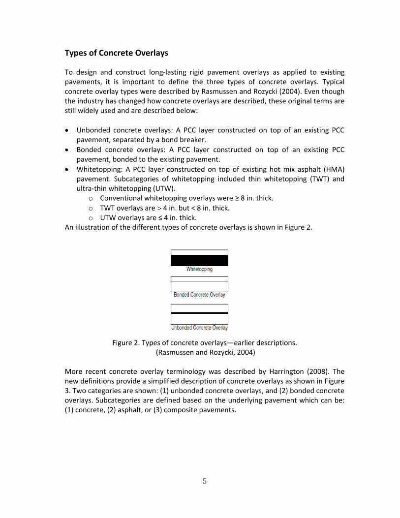
Types of Concrete Overlays
To design and construct long-lasting rigid pavement overlays as applied to existing pavements, it is important to define the three types of concrete overlays. Typical concrete overlay types were described by Rasmussen and Rozycki (2004). Even though the industry has changed how concrete overlays are described, these original terms are still widely used and are described below:
Unbonded concrete overlays: A PCC layer constructed on top of an existing PCC pavement, separated by a bond breaker.
Bonded concrete overlays: A PCC layer constructed on top of an existing PCC pavement, bonded to the existing pavement.
Whitetopping: A PCC layer constructed on top of existing hot mix asphalt (HMA) pavement. Subcategories of whitetopping included thin whitetopping (TWT) and ultra-thin whitetopping (UTW).
o Conventional whitetopping overlays were ≥ 8 in. thick.
o TWT overlays are 4 in. but < 8 in. thick. o UTW overlays are ≤ 4 in. thick.
An illustration of the different types of concrete overlays is shown in Figure 2.
Figure 2. Types of concrete overlays—earlier descriptions.
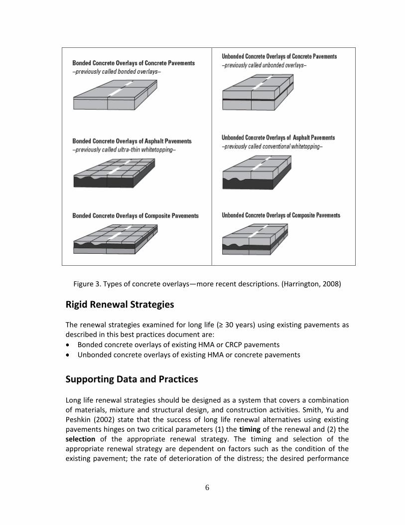
(Rasmussen and Rozycki, 2004) More recent concrete overlay terminology was described by Harrington (2008). The new definitions provide a simplified description of concrete overlays as shown in Figure 3. Two categories are shown: (1) unbonded concrete overlays, and (2) bonded concrete overlays. Subcategories are defined based on the underlying pavement which can be: (1) concrete, (2) asphalt, or (3) composite pavements.
6
Figure 3. Types of concrete overlays—more recent descriptions. (Harrington, 2008)
Rigid Renewal Strategies
The renewal strategies examined for long life (≥ 30 years) using existing pavements as described in this best practices document are:
Bonded concrete overlays of existing HMA or CRCP pavements
Unbonded concrete overlays of existing HMA or concrete pavements
Supporting Data and Practices
Long life renewal strategies should be designed as a system that covers a combination of materials, mixture and structural design, and construction activities. Smith, Yu and Peshkin (2002) state that the success of long life renewal alternatives using existing pavements hinges on two critical parameters (1) the timing of the renewal and (2) the selection of the appropriate renewal strategy. The timing and selection of the appropriate renewal strategy are dependent on factors such as the condition of the existing pavement; the rate of deterioration of the distress; the desired performance

7
life from the repair strategy; lane closures and traffic control considerations; and user costs. Given the definition of long life renewal strategies and the constraints of life expectancy associated with timing and selection of pavement renewal strategies, only unbonded concrete overlays (using HMA separator layers) of existing concrete and asphalt pavements are likely to perform adequately for 30 or more years. This conclusion is based on several sets of information which includes, but is not limited to, (1) existing pavement design criteria, (2) State DOT criteria and field projects, (3) LTPP results, (4) state field visits, and (5) the National Concrete Pavement Technology Center (Harrington, 2008). In addition to existing design procedures and State DOT practices, an extensive amount of pavement performance data has been collected over the last 20 years via the Long Term Pavement Performance (LTPP) program. These results, as relevant to long life rigid renewal best practices, are summarized in the Supplemental Documentation at the end of this Appendix. The pavement performance information presented in these best practices is largely based on field experiments and projects. Thus, a wide range of traffic conditions are not available; however, the thickness design information available in the study developed “app” does reflect the use of formal design processes and a wide range of traffic conditions. Given the information summarized, the performance of concrete overlays over existing HMA or concrete is a function of slab thickness and design details such as joints and remaining HMA thickness, condition of the existing concrete, aggregate type,
reinforcing, etc. Given Interstate types of traffic ( 1 million ESALs per year), Table 2 shows typical pavement lives that can be expected for various slab thicknesses along with bonding condition and joint details over existing HMA. The expected lives shown are tentative and reflect an extrapolation the field data reviewed. Based on TxDOT experience, CRCP overlays over existing CRCP can achieve a 20 year life for a range of thicknesses (those reviewed ranged from a minimum of 2 in. up to 6.5 in.). TxDOT has accumulated substantial experience on both design and construction practices for this type of overlay. The thinnest CRCP overlays appear to address functional issues with the existing pavement. The most commonly applied CRCP overlay found in the TxDOT literature is typically 4 in. thick; however, more recent designs in the Houston area have been in the range of 6 to 8 in. thick (R23 Houston Trip Report). Only unbonded concrete overlays ≥ 8 in. thick meet the threshold for long life as defined in this study. This assumes that thicker bonded overlays (≥ 7 in. thick) are rarely applied.

8
Table 2. Bonded and unbonded JPCP concrete overlays over existing HMA with 1 million ESALs per year with sufficient existing HMA thickness
Slab Thickness (in.) Bonded or
Unbonded
Joints Dowels? Expected Life (years)
3 Bonded 5 ft by 6 ft No 5
4 Bonded 5 ft by 6 ft No 5 to 10
5 Bonded 5 ft by 6 ft No 10 to 15
6 Bonded 6 ft by 6 ft No 15 to 20
7 Bonded 6 ft by 6 ft Optional 20 to 25
8 Unbonded 12 ft by 12 ft Yes 25 to 30
9 Unbonded 15 ft by 12 ft Yes 30 to 35
Note: Additional information about this table is contained in the Supplemental Documentation at the end of this Appendix.
Concepts for Developing Long Life Renewal Strategies Commonly accepted criteria for defining long life concrete pavement performance (Tayabji and Lim, 2007) were described previously. For the purposes of this document, those criteria are generally applicable, although the performance life requirement has been extended to 30 to 50 years. Long performance life, in combination with good ride quality and minimal distress, cannot be achieved with increased pavement thickness or improved structural design alone. It requires the selection of durable component materials, proper mixture proportioning, comprehensive structural design, and best practices for construction to ensure acceptable long-term performance. Furthermore, it must be recognized that changes in one design or construction parameter (thickness or curing practices, for example) may have implications for the selection of other design parameters (joint spacing, for example). In other words, the pavement structure, materials, and construction practices must be recognized as a system where the failure of any one component (whether structural, functional, or related to durability) results in a system that will not achieve the goal of long life. One general concept or approach for developing a long-life pavement design or renewal strategy is to identify potential failure mechanisms and address each of them in the design, construction, and/or materials specifications. There are many potential failure mechanisms that may limit the performance life of a given pavement structure, and each of these mechanisms can be addressed in the materials, design, and construction specifications and procedures. Key considerations often include:

9
Foundation support (uniformity, volumetric stability [including stabilizing treatments])
Drainage design (moisture collection/removal and design for minimal maintenance)
Concrete mixture proportioning and components (selected to minimize shrinkage and potential for chemical attack, low CTE, provide adequate strength, etc.)
Dowels and reinforcing (corrosion resistance, sized and located for good load transfer)
Accuracy of design inputs
Construction parameters (including paving operations, surface texture, initial smoothness, etc.)
QA/QC (certification, pre-qualification, inspection, etc.)
All of the potential failure mechanisms (including those associated with structural or functional deterioration) must be addressed to ensure the pavement system achieves the desired level of performance over 30 to 50 or more years. Addressing only one or two distresses or design parameters (e.g., only pavement slab thickness and joint spacing to reduce uncontrolled cracking) while ignoring others (such as durability of materials and concrete curing practices) may postpone the development of some distresses for 30 to 50 or more years without preventing the pavement from failing due to other distresses in less than 30 years. The overall pavement performance life will be only as long as the “weakest link” (or shortest life) in the chain of factors that controls the system.
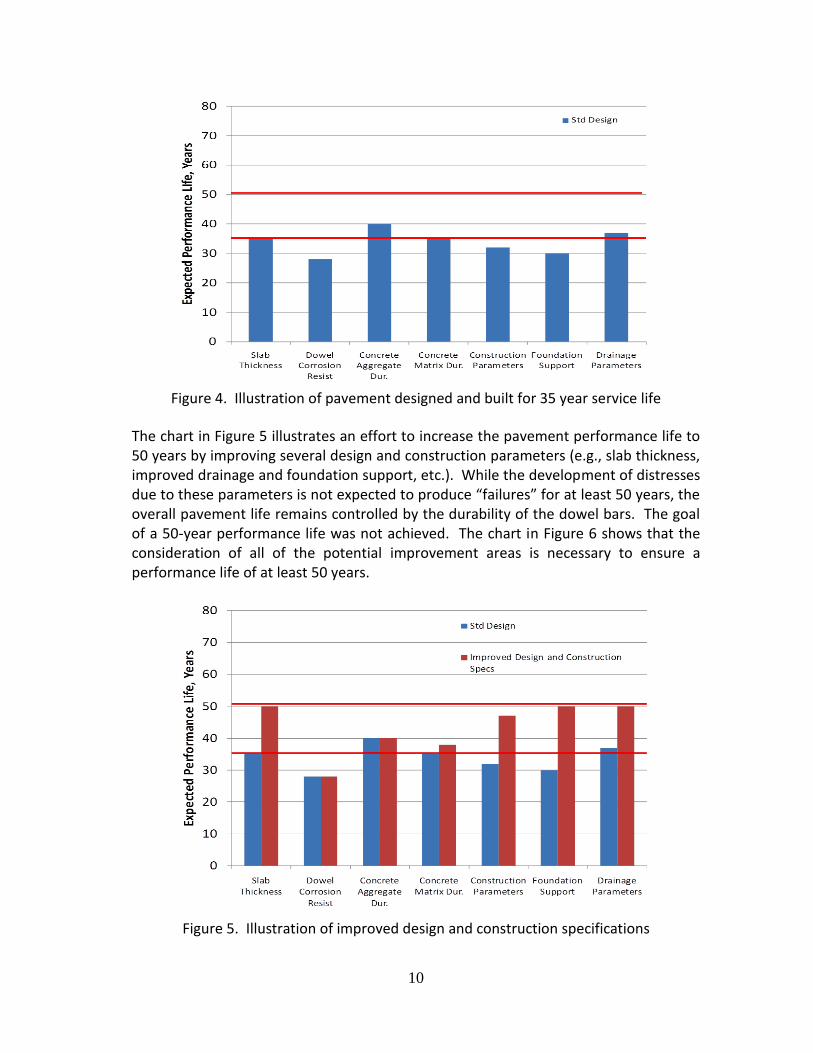
The need for a “systems approach” to long-life pavement renewal or design is illustrated in Figure 4. The chart presents an illustration of the expected performance life of an example standard pavement (with a 35-year nominal design life) due to the impacts of various design, materials and construction parameters. It can be seen that, for this example, all of the components being considered result in a life of about 35 years; if we consider the pavement to be “failed” when any of the component performances “fails”, then the expected life of this pavement is equal to the shortest component performance life (about 28 years in this case, limited by the dowel bar corrosion).
10
Figure 4. Illustration of pavement designed and built for 35 year service life
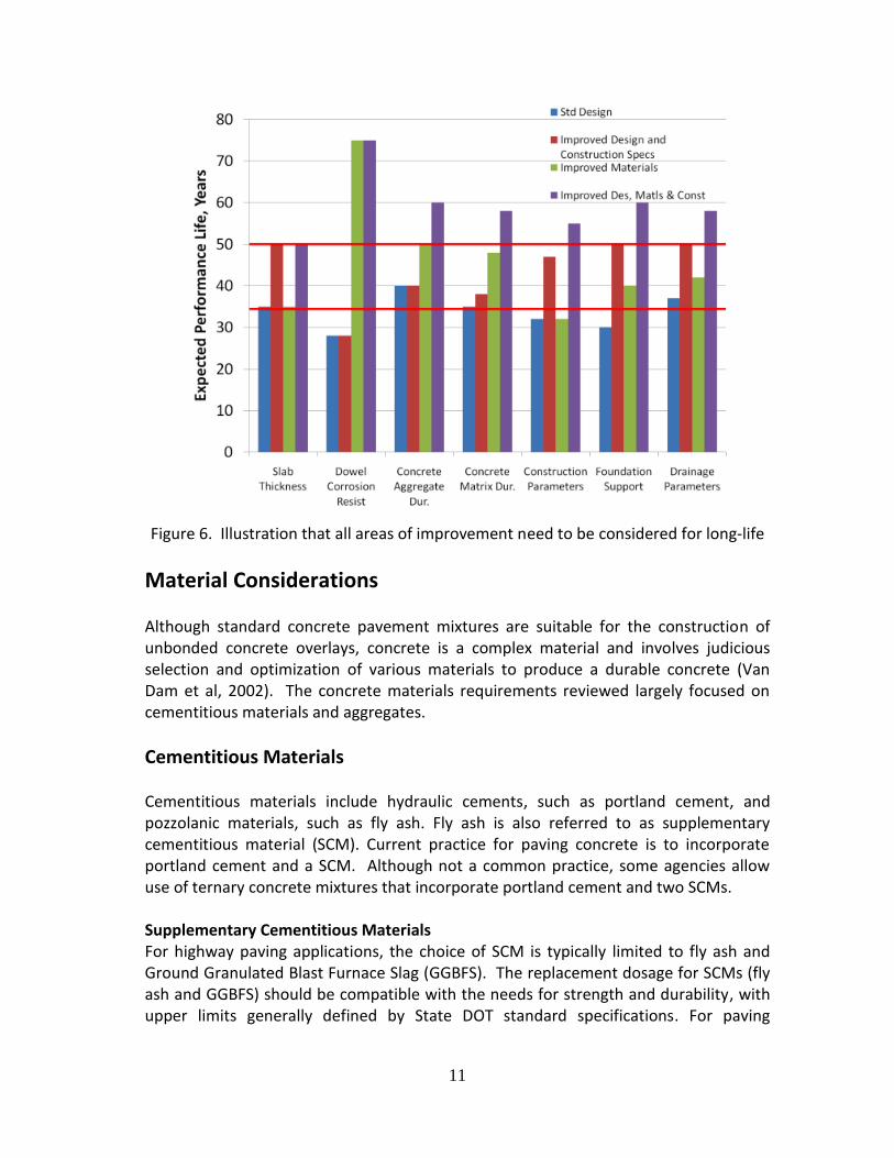
The chart in Figure 5 illustrates an effort to increase the pavement performance life to 50 years by improving several design and construction parameters (e.g., slab thickness, improved drainage and foundation support, etc.). While the development of distresses due to these parameters is not expected to produce “failures” for at least 50 years, the overall pavement life remains controlled by the durability of the dowel bars. The goal of a 50-year performance life was not achieved. The chart in Figure 6 shows that the consideration of all of the potential improvement areas is necessary to ensure a performance life of at least 50 years.
Figure 5. Illustration of improved design and construction specifications
11
Figure 6. Illustration that all areas of improvement need to be considered for long-life
Material Considerations Although standard concrete pavement mixtures are suitable for the construction of unbonded concrete overlays, concrete is a complex material and involves judicious selection and optimization of various materials to produce a durable concrete (Van Dam et al, 2002). The concrete materials requirements reviewed largely focused on cementitious materials and aggregates.
Cementitious Materials Cementitious materials include hydraulic cements, such as portland cement, and pozzolanic materials, such as fly ash. Fly ash is also referred to as supplementary cementitious material (SCM). Current practice for paving concrete is to incorporate portland cement and a SCM. Although not a common practice, some agencies allow use of ternary concrete mixtures that incorporate portland cement and two SCMs. Supplementary Cementitious Materials For highway paving applications, the choice of SCM is typically limited to fly ash and Ground Granulated Blast Furnace Slag (GGBFS). The replacement dosage for SCMs (fly ash and GGBFS) should be compatible with the needs for strength and durability, with upper limits generally defined by State DOT standard specifications. For paving

12
applications, the desired SCM content should be established considering durability concerns (ASR), if applicable, along with economic and sustainability considerations. Fly ash and slag are covered under the Environmental Protection Agency’s Comprehensive Procurement Guidelines (CPG) (EPA, 2011). The CPGs are Federal Law that requires federally funded construction projects to include certain recycled materials in construction specifications. Concrete specifications, therefore, must include provisions that allow use of fly ash and slag. The CPGs state that no preference should be given to one of these materials over another; rather, they should all be included in the specification. The enabling federal legislation is from the Resource Conservation and Recovery Act (RCRA).
Fly Ash Fly ash must meet the requirements of ASTM C 618; however, care should be taken in applying ASTM C 618, as it is rather broad. Class F fly ash is the preferred choice for controlling ASR, and it also improves sulfate resistance. Selection of fly ash type and dosage for ASR mitigation should be based on local best practices. A photo of Class F fly ash is shown in Figure 7. Typical dosages for Class F fly ash are generally between 15 percent and 25 percent by mass of cementitious materials. Sources must be evaluated for typical usage rates. As the amount of fly ash increases, some air entraining and water reducing admixtures are not as effective and require higher dosage rates due to interactions with the carbon in the fly ash. While ASTM C 618 permits up to 6% loss on ignition (LOI), the state DOTs should establish their own LOI limits. Changes in LOI can result in changes to the amount of air-entraining admixture required in the mixture. If fly ash will be used to control expansion due to ASR, the lower the CaO content the more effective it will be. Ideally, the CaO content should not exceed 8 percent.
Figure 7. Class F fly ash. (Photo: FHWA) Slag Cements and Ground Granulated Blast Furnace Slag (GGBFS) In the recent past, cement typically used in concrete pavements was traditional portland cement Type I or II (occasionally Type III for decreased cure times). Today, a wider range of cements are available, including slag cements and cements that are combinations of portland and slag cement.

13
Blast furnace slag is a by-product of manufacturing molten iron in a blast furnace. This granular material (Figure 8) results when the molten slag is quenched with water. The rapid cooling forms glassy silicates and aluminosilicates of calcium. Once ground to a suitable particle size, the end result is GGBFS. This is commonly referred to as “slag cement” (SCA, 2002).
GGBFS must meet the requirements of ASTM C 989. The following three grades are based on their activity index:
1. Grade 80. This is the least reactive and is typically not used for highway or airport projects.
2. Grade 100. This is moderately reactive. 3. Grade 120. This is the most reactive, with the increased activity achieved
through finer grinding. Grade 120 can be difficult to obtain in some regions of the US.
It is common that blends of slag and portland cements are made (typically designated Type IS(X) where X = the % of GGBFS). Typical dosages of slag should be between 25 percent and 50 percent of cementitious materials. Concrete strength at early ages (up to 28 days) may be lower using slag-cement combinations, particularly at low temperatures or at high slag percentages. The desired slag content must be established considering the importance of early strengths for the panel fabrication process. However, if the slag will be used to control expansions due to ASR, the minimum slag content used is that needed to control ASR.
Figure 8. Preprocessed blast furnace slag. (Photos: J. Mahoney)
Aggregates
Aggregates are a key component of concrete and can affect the properties of both fresh and hardened concrete. This is, in part, due to 70 to 80 percent of the PCC

14
volume being composed of aggregates. Aggregate selection should maximize the volume of aggregate in the concrete mixture in order to minimize the volume of cementitious paste (without compromising the durability and strength of the concrete mixture). Aggregate requirements for pavement concrete are typically established in accordance with the requirements of ASTM C33. Some of the key aggregate requirements are discussed below. Tables 3 and 4 summarize the relationship between aggregate properties and possible pavement distresses and standard test methods (Folliard and Smith, 2003), and illustrate the critical roles of competent aggregates. Figure 9 shows typical aggregate processing prior to batching concrete for paving. Maximum Aggregate Size The concern with aggregate size involves selecting an aggregate that will maximize aggregate volume and minimize cementitious material volume. In general, the larger the maximum size of the coarse aggregate, the less cementitious material is required, potentially leading to lower costs. Use of smaller maximum size aggregate (e.g., 0.75-in. maximum size) is required for D-cracking regions. However, the use of 0.75-in. maximum aggregate size alone does not prevent D-cracking, and many state agencies have criteria for D-cracking other than maximum aggregate size. Aggregate Gradation In the past, paving concrete was produced using coarse and fine aggregates. Today, agencies are moving toward the use of a combined gradation that may require use of more than two aggregate sizes. A combined gradation is based on an 8-to-18 specification. The percentage retained on all specified standard sieves should be between 8 and 18 percent, except the coarsest sieve and finer than the No. 30 sieve. The coarseness factor differentiates between gap graded and well graded aggregate gradations, whereas the workability factor determines the mix coarseness. Concrete made with combined aggregate gradation has improved workability for slipform paving applications, requires use of less cementitious materials, exhibits less drying shrinkage, and may be more economical (Richardson, 2005).

15
Figure 9. Aggregate processing, which includes stockpiles, conveyors, and screening.
(Photos: J. Mahoney)

16
Table 3. Concrete pavement performance parameters affected by aggregate properties. (after Folliard and Smith, 2003)
Performance Parameter
Manifestation Mechanism(s) PCC Properties Aggregate Properties
Alkali-Aggregate Reactivity
Shallow map cracking and joint/crack spalling, accompanied by staining
Chemical reaction between alkalis in cement paste and either susceptible siliceous or carbonate aggregates
Mineralogy
Size
Porosity
Blowups Upward lifting of PCC slabs at joints or cracks, often accompanied by shattered PCC
Excessive expansive pressures caused by incompressibles in joints, alkali-aggregate reactivity (AAR), or extremely high temperature or moisture conditions
Coefficient of thermal expansion
Coefficient of thermal expansion
Mineralogy
D-Cracking Crescent-shaped hairline cracking generally occurring at joints and cracks in an hourglass shape
Water in aggregate pores freezes and expands, cracking the aggregate and/or surrounding mortar
Air void quality Mineralogy
Pore size distribution
Size
Longitudinal Cracking
Cracking occurring parallel to the centerline of the pavement
Late or inadequate joint sawing, presence of alkali-silica reactivity (ASR), expansive pressures, reflection cracking from underlying layer, traffic loading, loss of support
Coefficient of thermal expansion
Coarse aggregate-mortar bond
Shrinkage
Coefficient of thermal expansion
Gradation
Size
Mineralogy
Shape, angularity, and texture
Hardness
Abrasion resistance
Strength
Roughness Any surface deviations that detract from the rideability of the pavement
Development of pavement distresses, foundation instabilities, or “built in” during construction
Any that affects distresses
Elastic modulus
Workability
Any that affect distresses
Gradation
Elastic modulus
Spalling Cracking, chipping, breaking, or fraying of PCC within a few feet of joints or cracks
Incompressibles in joints, D-cracking or AAR, curling/ warping, localized weak areas in PCC, embedded steel, poor freeze-thaw durability
Coefficient of thermal expansion
Coarse aggregate-mortar bond
Workability
Durability
Strength
Air-void quality
Shrinkage
Gradation
Mineralogy
Texture
Strength
Elastic modulus
Size
Surface Friction Force developed at tire-pavement interface that resists sliding when braking forces applied
Final pavement finish and texture of aggregate particles (mainly fine aggregates)
Hardness
Shape, angularity, and texture
Mineralogy
Abrasion resistance

17
Table 3. Continued. Performance
Parameter Manifestation Mechanism(s) PCC Properties Aggregate
Properties Transverse Cracking
Cracking occurring perpendicular to the centerline of the pavement
PCC shrinkage, thermal shrinkage, traffic loading, curling/warping, late or inadequate sawing, reflection cracking from underlying layer, loss of support
Shrinkage
Coarse aggregate-mortar bond
Coefficient of thermal expansion
Strength
Coefficient of thermal expansion
Gradation
Size
Shape, angularity, and texture
Mineralogy
Hardness
Abrasion resistance
Strength
Corner Breaks (Jointed PCC)
Diagonal cracks occurring near the juncture of the transverse joint and the longitudinal joint or free edge
Loss of support beneath the slab corner, upward slab curling
Strength
Coarse aggregate-mortar bond
Coefficient of thermal expansion
Elastic modulus
Coefficient of thermal expansion
Gradation
Size
Mineralogy
Shape, angularity, and texture
Hardness
Abrasion resistance
Strength
Transverse Joint Faulting (Jointed PCC)
Difference in elevation across transverse joints
Pumping of fines beneath approach side of joint, settlements or other foundation instabilities
Elastic modulus Size
Gradation
Shape, angularity, and texture
Abrasion resistance
Elastic modulus
Coefficient of thermal expansion
Punchouts (CRCP)
Localized areas of distress characterized by two closely spaced transverse cracks intersected by a longitudinal crack
Loss of support beneath slab edges and high deflections
Elastic modulus
Strength
Shrinkage
Coefficient of thermal expansion
Elastic modulus
Strength
Coefficient of thermal expansion
Size
Shape, angularity, and texture
Abrasion resistance

18
Table 4. Standard aggregate, aggregate related and PCC test methods. (Folliard and Smith (2003)
Property Test Method
Basic Aggregate Property
Grading AASHTO T 27 Specific gravity AASHTO T 84
Absorption AASHTO T 84
Unit weight AASHTO T 19
Petrographic analysis ASTM C 295
Durability
Soundness AASHTO T 104 F-T resistance AASHTO T 161 Internal pore structure AASHTO T 85
Degradation resistance AASHTO T 96, ASTM C 535
Chemical reactivity ASR
ASTM C 227, 295, 289
ACR ASTM C 295 Dimensional change Drying shrinkage ASTM C 157 Deleterious substances AASHTO T 21 Frictional resistance AASHTO T 242 Particle shape and texture ASTM D 4791
Deleterious Substances Deleterious substances are contaminants that are detrimental to the aggregate’s use in concrete. ASTM C 33 lists the following as deleterious substances:
Clay lumps and friable particles
Chert (with saturated surface dry specific gravity < 2.40)
Material finer than No. 200 sieve
Coal and lignite Inclusion of larger than allowable amounts of the deleterious substances can seriously impact both the strength and durability of concrete. Soundness The soundness test measures the aggregate’s resistance to weathering, particularly frost resistance. The ASTM C 88 test for soundness has a poor precision record. Aggregates that fail this test may be re-evaluated using ASTM C 666 or judged on the basis of local service history. Flat and Elongated Particles Flat and elongated particles impact workability of fresh concrete and may negatively affect the strength of hardened concrete. The amount of such particles needs to be limited. The breakdown of aggregates, especially the breakdown of fine aggregates, during handling and later when mixed in the concrete may lead to the production of excess microfines. This aggregate breakdown tends to negatively affect concrete
19
workability, ability to entrain air, and constructability (i.e., placing, compacting, and finishing). Increasing water content to offset the reduction in workability would increase the w/c ratio and lead to lower strength and an increased potential of plastic and drying shrinkage (Folliard and Smith, 2003). Los Angeles Abrasion Test The Los Angeles Abrasion Test provides a relative assessment of the hardness of the aggregate. Harder aggregates maintain skid resistance longer and provide an indicator of aggregate quality. Durability (D-Cracking) Durability cracking (D-cracking) is a concern for coarse aggregate particles that typically
are (1) sedimentary in origin, (2) have a high porosity, (3) small pore size (about 0.1
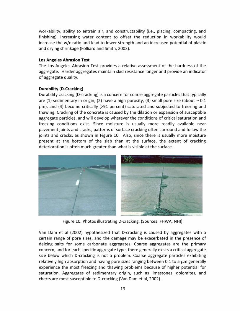
m), and (4) become critically (>91 percent) saturated and subjected to freezing and thawing. Cracking of the concrete is caused by the dilation or expansion of susceptible aggregate particles, and will develop wherever the conditions of critical saturation and freezing conditions exist. Since moisture is usually more readily available near pavement joints and cracks, patterns of surface cracking often surround and follow the joints and cracks, as shown in Figure 10. Also, since there is usually more moisture present at the bottom of the slab than at the surface, the extent of cracking deterioration is often much greater than what is visible at the surface.
Figure 10. Photos illustrating D-cracking. (Sources: FHWA, NHI)
Van Dam et al (2002) hypothesized that D-cracking is caused by aggregates with a certain range of pore sizes, and the damage may be exacerbated in the presence of deicing salts for some carbonate aggregates. Coarse aggregates are the primary concern, and for each specific aggregate type, there generally exists a critical aggregate size below which D-cracking is not a problem. Coarse aggregate particles exhibiting
relatively high absorption and having pore sizes ranging between 0.1 to 5 m generally experience the most freezing and thawing problems because of higher potential for saturation. Aggregates of sedimentary origin, such as limestones, dolomites, and cherts are most susceptible to D-cracking (Van Dam et al, 2002).

20
Alkali-Aggregate Reactivity (AAR) Two types of AAR reaction are recognized, and each is a function of the reactive mineral; silicon dioxide or silica (SiO2) minerals are associated with alkali-silica reaction (ASR) and calcium magnesium carbonate (CaMg(CO3))2 or dolomite) minerals with alkali-carbonate reaction (ACR) (Thomas et al, 2008). Both types of reaction can result in expansion and cracking of concrete elements, leading to a reduction in the service life of concrete structures. A process for identifying whether there is (or could be) a problem with AAR is illustrated in Figure 11.
Figure 11. Evaluation Stages for Alkali-Aggregate Reaction Determination.
(from Thomas et al, 2008) Alkali-silica reaction (ASR) is of more concern since the aggregates associated with it are common in pavement construction. ASR is a deleterious chemical reaction between reactive silica constituents in aggregates and alkali hydroxides in the hardened cement paste. This constituent of concrete has a pore structure, and the associated pore water is an alkaline solution. This alkaline condition, plus reactive silica provided by the aggregate produces a gel. The gel, unfortunately, has an affinity for water, which in turn grows and produces expansive stresses. These stresses generate polygonal

21
cracking either within the aggregate, the mortar, or both that over time can compromise the structural integrity of concrete. Concrete undergoing ASR often exhibits telltale signs of surface map cracking as illustrated by Figures 12 and 13. It is widely accepted that high pH (> 13.2) pore water in combination with an optimum amount of reactive siliceous aggregate are key ingredients to initiate ASR expansion; it is also believed that a relative humidity (RH) ≥ 85 percent is essential for ASR to occur. Although the problem is widely known, and successful mitigation methods are available, ASR continues to be a concern for concrete pavement. Aggregates susceptible to ASR are either those composed of poorly crystalline or metastable silica materials, which usually react relatively quickly and result in cracking within 5 to 10 years, or those involving certain varieties of quartz, which are slower to react in field applications. ASR research is on-going and the provisions associated with ASR related testing are based on best current practices. Guidelines related to ASR will continue to be updated or replaced as more research becomes available. AASHTO has issued a Provisional Practice—AASHTO Designation PP 65-10—to address ASR. The full title of PP 65-10 is “Determining the Reactivity of Concrete Aggregates and Selecting Measures for Preventing Deleterious Expansion in New Concrete Construction.” Additionally, reports from the PCA (Farney and Kosmatka, 1997) and the FHWA (Thomas et al, 2008; Fournier et al, 2010) provide solid explanations on why ASR occurs, how it can be assessed, and mitigation measures that can be taken.
Figure 12. Illustration of ASR on a traffic barrier. (FHWA)

22
Figure 13. Illustration of ASR in concrete pavements. (Source: D. Huft, South Dakota DOT)
Coefficient of Thermal Expansion The coefficient of thermal expansion (CTE) plays an important role in PCC joint design (including joint width and slab length) and in accurately computing pavement stresses (especially curling stresses) and joint load transfer efficiency (LTE) over the design life; thus, the lower the CTE, the better for concrete pavements. The CTE of concrete is highly dependent upon the CTEs of the concrete components and their relative proportions (as well as the degree of saturation of the concrete). Cement paste CTE increases with water-to-cement ratio, and cement pastes generally have higher CTEs than concrete aggregates (as shown in Table 5). Therefore, the concrete aggregate, which typically comprises 70 percent or more of the volume of concrete, tends to control the CTE of the hardened concrete: more aggregate and lower CTE aggregate results in concrete with lower CTE values. It should be noted that critical internal stresses may develop in the PCC if the thermal expansion characteristics of the matrix and the aggregates are substantially different, and large temperature changes take place. Field sections in Texas clearly demonstrated the superior qualities of their limestone versus siliceous aggregates as used in bonded concrete overlays (Kim et al, 2012).

23
Table 5. Typical CTE ranges for common PCC components. (ARA, 2004)
Material Type Typical Coefficient of Thermal Expansion (10-6/oF)
Aggregate
Limestone 3.4-5.1
Granites and Gneisses 3.8-5.3
Basalt 4.4-5.3
Dolomites 5.1-6.4
Sandstones 5.6-6.5
Quartz Sands and Gravels 6.0-8.7
Quartzite, Cherts 6.6-7.1
Cement Paste w/c ratio 0.4 to 0.6 10.0-11.0
Concrete Cores from LTPP Sections 4.0 (lowest), 5.5 (mean), 7.2 (highest)
Chemical Admixtures A number of chemical admixtures can be added to concrete during proportioning or mixing to enhance the properties of fresh and/or hardened concrete. Admixtures commonly used in mixtures include air entrainers and water reducers. The standard specification for chemical admixtures in concrete used in the United States is AASHTO M 194 (ASTM C 494). The use of chemical admixtures for concrete is a well-established practice and requires no additional provisions for application. High-range water reducers are typically not used with paving concrete.
Other Materials The characteristics of other materials used in the construction of unbonded concrete overlays are as follows:
Dowel bars should conform to the appropriate ASTM and AASHTO standards. The standard practice in the US is to specify use of epoxy coated dowel bars. However, the effectiveness of the current standard epoxy coating materials and processes beyond 15 to 25 years in service is considered suspect. Figure 14 shows epoxy coated dowels with less than 15 years of service in Washington State. It is noted that these photos are from retrofit dowel projects, which present challenges in consolidating the patching mix—a situation unlikely to occur in PCC overlays; however, voids in the vicinity of dowels are a concern. Corrosion has been noted for epoxy coated dowels by WSDOT on fully reconstructed JPCP construction following about 15 years of service. Several recent projects (MN, IL, IA, OH, and WA) have been constructed using stainless steel clad dowel bars (Figure 15) and zinc-clad dowel bars with satisfactory performance (FHWA, 2006). WSDOT requires corrosion resistant dowel bars for concrete pavements that have a design life of greater than 15 years. The long-life dowel options used by WSDOT include: (1)

24
stainless steel clad bars, (2) stainless steel tube bars whereby the tube is press fitted onto a plain steel inner bar, (3) stainless steel solid bars, (4) corrosion-resistant steel bars that conform to ASTM A1035, and (5) zinc clad bars (WSDOT, 2010). The Minnesota and Wisconsin DOTs have similar specifications for long-life dowel bars, with Minnesota allowing the use of hollow stainless steel tubes as an additional option, and neither state allowing the A1035 dowels (MnDOT, 2005b; Wisconsin DOT, 2009). Additional guidance on dowel bar design can be found in a recent publication by the Concrete Pavement Technology Center (CP Tech Center, 2011).
Tie bars should conform to the appropriate ASTM and AASHTO standards.
All joint cuts and sealant materials used should conform to the appropriate ASTM and AASHTO standards, or a governing state specification.
Figure 14. Corroded epoxy coated dowel bars in a retrofitted dowel bar project (original bars 1.5” by 18”). (Photos: WSDOT)

25
Figure 15. Stainless dowel bar. (Photo: J. Mahoney)
Unbonded Concrete Overlays of Concrete Pavements Criteria for Long-life Potential
This renewal strategy is applicable when the existing pavement exhibits extensive structural deterioration and possible material related distresses such as D-cracking or reactive aggregate (Smith et al (2002) and Harrington (2008)). The success of the strategy depends on the stability (structural integrity) and the uniformity of the underlying structure. Since the concrete overlay is “separated” from the underlying pavement, the pre-overlay repairs are usually held to a minimum. Figure 16 is a sketch of an unbonded overlay over concrete.
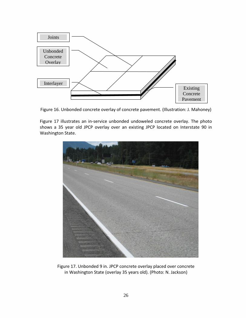
26
Figure 16. Unbonded concrete overlay of concrete pavement. (Illustration: J. Mahoney) Figure 17 illustrates an in-service unbonded undoweled concrete overlay. The photo shows a 35 year old JPCP overlay over an existing JPCP located on Interstate 90 in Washington State.
Figure 17. Unbonded 9 in. JPCP concrete overlay placed over concrete in Washington State (overlay 35 years old). (Photo: N. Jackson)
Joints
Unbonded
Concrete
Overlay
Interlayer Existing
Concrete
Pavement

27
The following sections summarize some of the design and construction issues to consider for long life unbonded concrete overlays.
General Design Considerations Smith et al (2002) and Harrington (2008) suggest that when designing unbonded concrete overlays, the following factors need to be considered:
The type and condition of the existing pavement. In general, unbonded concrete overlays are feasible when the existing pavement is in poor condition, including material-related distress such as sulfate attack, D-cracking, and ASR. The structural condition of the existing pavement can be established by (1) conducting visual distress surveys, (2) conducting deflection testing using a falling weight deflectometer (FWD) (the deflection magnitudes can be used to determine the load transfer efficiency across joints, possible support characteristics under the slab corners and edges, backcalculate the modulus of subgrade reaction and modulus of the existing portland cement concrete pavement, and variability of the foundation layers along the length of the project); and (3) extracting cores from the existing pavement. Laboratory testing of the cores is necessary if the existing pavement exhibits D-cracking or reactive aggregates.
Preoverlay repairs. One of the attractive features of this renewal strategy is that extensive preoverlay repairs are not warranted. It is recommended that only those distresses need to be addressed that can lead to a major loss in structural integrity and uniformity of support. The guidelines (Harrington, 2008) for conducting preoverlay repairs are summarized in Table 6.
Table 6. Guidelines for preoverlay repairs. (Harrington, 2008)
Existing Pavement Condition Possible Repairs
Faulting 10mm No repairs needed
Faulting > 10 mm Use a thicker interlayer
Significant tenting, shattered slabs, pumping Full-depth repairs
Severe joint spalling Clean the joints
CRCP w/punchouts Full-depth repairs
Separator layer design. The separator layer is a critical factor for the performance of the unbonded concrete overlay. The separator layer acts as a lower modulus buffer layer that assists in mitigating cracks from reflecting up from the existing pavement to the new overlay. The separator layer does not contribute significantly to the structural enhancement.
28
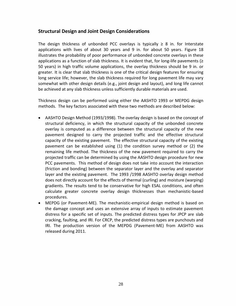
Structural Design and Joint Design Considerations The design thickness of unbonded PCC overlays is typically ≥ 8 in. for Interstate applications with lives of about 30 years and 9 in. for about 50 years. Figure 18 illustrates the probability of poor performance of unbonded concrete overlays in these applications as a function of slab thickness. It is evident that, for long-life pavements (≥ 50 years) in high traffic volume applications, the overlay thickness should be 9 in. or greater. It is clear that slab thickness is one of the critical design features for ensuring long service life; however, the slab thickness required for long pavement life may vary somewhat with other design details (e.g., joint design and layout), and long life cannot be achieved at any slab thickness unless sufficiently durable materials are used. Thickness design can be performed using either the AASHTO 1993 or MEPDG design methods. The key factors associated with these two methods are described below:
AASHTO Design Method (1993/1998). The overlay design is based on the concept of structural deficiency, in which the structural capacity of the unbonded concrete overlay is computed as a difference between the structural capacity of the new pavement designed to carry the projected traffic and the effective structural capacity of the existing pavement. The effective structural capacity of the existing pavement can be established using (1) the condition survey method or (2) the remaining life method. The thickness of the new pavement required to carry the projected traffic can be determined by using the AASHTO design procedure for new PCC pavements. This method of design does not take into account the interaction (friction and bonding) between the separator layer and the overlay and separator layer and the existing pavement. The 1993 /1998 AASHTO overlay design method does not directly account for the effects of thermal (curling) and moisture (warping) gradients. The results tend to be conservative for high ESAL conditions, and often calculate greater concrete overlay design thicknesses than mechanistic-based procedures.
MEPDG (or Pavement-ME). The mechanistic-empirical design method is based on the damage concept and uses an extensive array of inputs to estimate pavement distress for a specific set of inputs. The predicted distress types for JPCP are slab cracking, faulting, and IRI. For CRCP, the predicted distress types are punchouts and IRI. The production version of the MEPDG (Pavement-ME) from AASHTO was released during 2011.

29
Figure 18. Slab thickness versus probability of poor performance for unbonded
JPCP overlays. (Smith et al, 2002) Joint design is one of the factors affecting jointed pavement performance. It also affects the thickness design for overlays. The joint design process includes joint spacing, joint width, and load transfer design (dowel bars and tie bars). Size, layout, and coating of the dowel bars depend on the project location and traffic levels. Load transfer in unbonded concrete resurfacing is typically very good – comparable to that of new JPCP on HMA base, and better than that of JPCP on untreated base. Doweled joints should be used for unbonded resurfacing on pavements that will experience significant truck traffic (i.e., typically for concrete overlay thicknesses of 9 in. or more). Several studies have shown that adequately sized dowels must be provided to obtain good faulting performance (Snyder et al. 1989; Smith et al. 1997). Dowel diameter is often selected based on slab thickness, but traffic may be a more important factor for consideration. For long-life pavements, 1.5 in. diameter bars are usually recommended. Additionally, corrosion-resistant dowels (e.g., stainless steel-surfaced, non-stainless corrosion resistant steel (ASTM A1035), and zinc-clad steel alternatives) are required by those State DOTs considering long life designs. Details concerning the design of dowel load transfer systems can be found in a recent publication prepared by the National Concrete Consortium (CP Tech Center, 2011). Examples of three state DOT specifications and special provisions for the use of corrosion-resistant dowels were cited earlier.

30
It is recommended that shorter joint spacings be used to reduce the risk of early cracking due to curling stresses. A maximum joint spacing of 15 feet is typically used for thick (> 9 in.) long-lived concrete pavements. Figure 19 illustrates a typical joint mismatching detail, which should be considered for jointed concrete overlays. Prior recommendations suggest that the transverse joints should be sawed to a depth of T/4 (minimum) to T/3 (maximum) (Smith et al [2002], Harrington [2008]).
Figure 19. Joint mismatching details. (Smith et al, 2002)
Drainage Design Drainage system quality significantly affects pavement performance. Overlay drainage design depends on the performance and capacity of the existing drainage system. Consequently, evaluation of the existing pavement is the first step in overlay drainage design. Depending on the outcome of this evaluation, no upgrade may be necessary. However, in the presence of distresses caused by moisture, appropriate design measures must be employed to address these issues. Distresses such as faulting, pumping, and corner breaks could be indicators of a poor drainage system. Standing water might be an indication of insufficient cross-slope. Proper design, along with good construction and maintenance, will reduce these types of distresses. If asphalt interlayer drainage is inadequate in an unbonded PCC overlay, pore pressure induced by heavy traffic may cause HMA layer stripping, so careful consideration and design for interlayer drainage should be followed (Smith et al (2002), Harrington (2008)).
Separator Layers The separator layer is a critical factor in determining the performance of an unbonded concrete overlay. The separator layer acts as a lower modulus buffer layer that assists in preventing cracks from reflecting up from the existing pavement to and through the new overlay. The separator layer does not contribute significantly to the structural

31
enhancement and, therefore, the use of excessively thick (e.g., > 2 inches) separator layers should be avoided (Smith et al (2002), Harrington (2008)). Interlayers should be between 1 to 2 in. thick (Smith et al [2002], Harrington [2008]). Thin interlayers (e.g., 1 inch) have been used successfully when the existing pavement has little faulting or other surface distress. Thicker separator layers have been used when faulting and distress levels are high. The use of dense-graded and permeable HMA interlayers is common. Other materials used in unbonded overlay interlayers (either alone or in conjunction with HMA material) include polyethylene sheeting, liquid asphalts, geotextile fabrics, chip seals, slurry seals, and wax-based curing compounds. Not all of these materials and material combinations may be suitable for long-life pavements.
In Germany, a non-woven fabric material is placed between the stabilized subbase and concrete slab to prevent bonding between layers, and to provide a medium for subsurface drainage. This technology has been adapted for use in the US for unbonded concrete overlay interlayers, and was showcased on a 2008 unbonded concrete overlay project in Missouri (Tayabji et al, 2009). Figure 20 illustrates the placement of the fabric on the existing pavement surface. It is noted that no long-term performance data is currently available for the application of this technology in concrete overlays.
Figure 20. Placement of non-woven fabric as an interlayer. (From Tayabji et al [2009]) Table 7 summarizes the types of interlayers currently used in the construction of unbonded concrete overlays for concrete pavements. This information is based on extended meetings with pavement engineering and management professionals from

32
the Illinois Tollway Authority, and the Michigan, Minnesota, and Missouri Departments of Transportation.
Table 7. Example state of practice regarding the use of interlayers.
State DOT Interlayer Material
Illinois Tollway Authority Used rich sand asphalt layer for one project.
Michigan
Experienced problems with thick sandy layers. Moved to using open-graded interlayer with a uniform thickness. The HMA separation layer is constructed in either a uniform 1 in. or 1 to 3 in. moderately wedged section. Geometric issues are corrected with the thickness of the PCC overlay.
Minnesota Typically use an open-graded interlayer, but have also milled existing HMA to a 2 in. thickness and utilized as an interlayer.
Missouri Typically use a 1 in. HMA or geotextile interlayer.
As reported by Smith et al (2002), the most commonly used separator layer is HMA (69 percent). Although other types of separator layers are also used, bituminous materials make up 91 percent of all separator layer types. Performance Considerations The performance of unbonded concrete overlays from the LTPP General Pavement Studies (GPS-9) sections is presented in this section. The pavement performance criteria selected for the summary includes transverse cracking, IRI (and PSI), joint and crack faulting. The performance trends presented in this section are based on measurements documented in the latest year of monitoring available. Transverse Cracking Figure 21 shows typical transverse cracks both for airfield and highway pavements. Figure 22 shows the magnitude of average number of transverse cracks per 500 ft. long section for the LTPP GPS-9 sections as a function of overlay thickness for jointed concrete pavements. As expected the thicker overlays (> 8 to 9 in.) exhibit fewer transverse cracks. It is noted that 11 of the 14 jointed concrete pavement overlays exhibited little or no cracking in 18 years of service. These test sections do exhibit the promise of long life performance.

33
Figure 21. Illustrations of transverse cracking on an airport apron and an Interstate
Highway. (Photos: Joe Mahoney)
Figure 22. JPCP overlay thickness versus average number of transverse cracks.
International Roughness Index (IRI) Figure 23 illustrates the progression of IRI and PSI for the various GPS 9 sections and the impact of overlay thickness on ride quality.
0
2
4
6
8
10
12
14
5.1" - 6.5" 6.6" - 8" 8.1" - 9.5" 9.6" - 11"
Overlay Thickness
Avg
. N
o.
of
TC
(L
ast
Su
rvey)

34
Figure 23. Overlay thickness versus average IRI and average PSI
(pavement age ranges from 6-20 years).
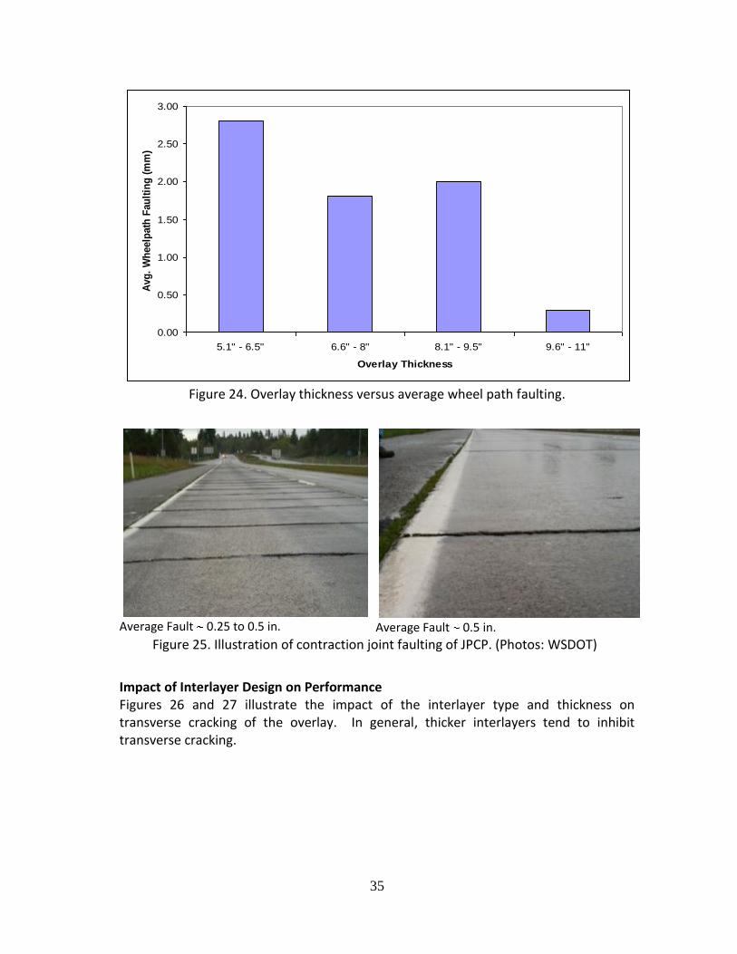
Joint and Crack Faulting Figure 24 illustrates transverse contraction joint faulting (faulting above 0.25 in. is significant); although, the data from GPS-9 projects does not show the degree of severity that is illustrated in Figure 25. The overall magnitude of the faulting is below
0.25 in. and therefore does not appear to be an issue; however, slab thicknesses 9.6 in. show significantly less faulting, perhaps due to the use of dowel bars in these thicker pavements. The thinner overlays in the GPS-9 experiment were not doweled, so the trends are probably more due to the use of dowels rather than pavement thickness, but that may simply imply that the pavement needs to be thick enough to install dowels. The use of properly designed dowels in the transverse joints should essentially eliminate transverse joint faulting.
0.00
0.50
1.00
1.50
2.00
2.50
3.00
3.50
4.00
5.1" - 6.5" 6.6" - 8" 8.1" - 9.5" 9.6" - 11"
Overlay Thickness
Avg
. IR
I (m
/km
)
0.0
1.0
2.0
3.0
4.0
5.0
Avg
. P
SI
IRI PSI
35
Figure 24. Overlay thickness versus average wheel path faulting.
Average Fault 0.25 to 0.5 in. Average Fault 0.5 in.
Figure 25. Illustration of contraction joint faulting of JPCP. (Photos: WSDOT)
Impact of Interlayer Design on Performance Figures 26 and 27 illustrate the impact of the interlayer type and thickness on transverse cracking of the overlay. In general, thicker interlayers tend to inhibit transverse cracking.
0.00
0.50
1.00
1.50
2.00
2.50
3.00
5.1" - 6.5" 6.6" - 8" 8.1" - 9.5" 9.6" - 11"
Overlay Thickness
Avg
. W
heelp
ath
Fau
ltin
g (
mm
)

36
Figure 26. JPCP interlayer type versus average number of transverse cracks.
Figure 27. JPCP interlayer thickness versus average number of transverse cracks.
0
5
10
15
20
25
30
Dense Graded
Asphalt Concrete
Open Graded
Asphalt Concrete
Chip Seal Other No Interlayer
Interlayer Type
Avg
. N
o.
of
TC
(L
ast
Su
rvey)
0
2
4
6
8
10
12
14
0" 0.1" - 1.9" 2" - 3.8" > 3.9"
Interlayer Thickness
Avg
. N
o.
of
TC
(L
ast
Su
rvey)
37
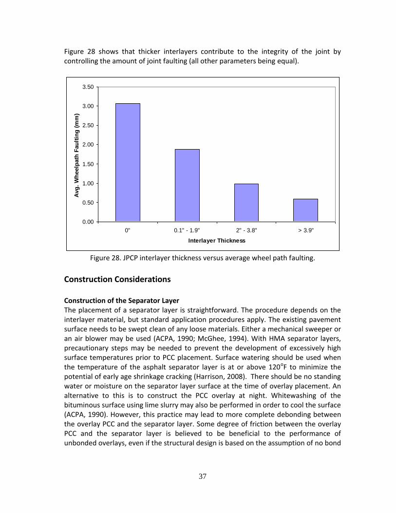
Figure 28 shows that thicker interlayers contribute to the integrity of the joint by controlling the amount of joint faulting (all other parameters being equal).
Figure 28. JPCP interlayer thickness versus average wheel path faulting.
Construction Considerations Construction of the Separator Layer The placement of a separator layer is straightforward. The procedure depends on the interlayer material, but standard application procedures apply. The existing pavement surface needs to be swept clean of any loose materials. Either a mechanical sweeper or an air blower may be used (ACPA, 1990; McGhee, 1994). With HMA separator layers, precautionary steps may be needed to prevent the development of excessively high surface temperatures prior to PCC placement. Surface watering should be used when the temperature of the asphalt separator layer is at or above 120oF to minimize the potential of early age shrinkage cracking (Harrison, 2008). There should be no standing water or moisture on the separator layer surface at the time of overlay placement. An alternative to this is to construct the PCC overlay at night. Whitewashing of the bituminous surface using lime slurry may also be performed in order to cool the surface (ACPA, 1990). However, this practice may lead to more complete debonding between the overlay PCC and the separator layer. Some degree of friction between the overlay PCC and the separator layer is believed to be beneficial to the performance of unbonded overlays, even if the structural design is based on the assumption of no bond
0.00
0.50
1.00
1.50
2.00
2.50
3.00
3.50
0" 0.1" - 1.9" 2" - 3.8" > 3.9"
Interlayer Thickness
Avg
. W
heelp
ath
Fau
ltin
g (
mm
)

38
(ERES, 1999). The size of the project and geometric constraints will determine the type of paving (fixed form, slip form or a combination) used (Smith et al, 2002). Concrete Temperature During Construction During construction, excessively high temperature and moisture gradients through the PCC must be avoided through the use of good curing practices (i.e., control of concrete temperature and moisture loss). Several studies have shown that excessive temperature and/or moisture gradients through the PCC slab at early ages (particularly during the first 72 hours after placement) can induce a significant amount of curling into PCC slabs, which can then result in higher slab stresses and premature slab cracking. This built-in construction curling is of particular concern for unbonded overlays because of the very stiff support conditions typically present. Early age (less than 72 hours) characterization of the pavement should be performed to study the impact of PCC mixture characteristics and climatic conditions at the time of construction on the predicted overlay behavior and performance. An excellent tool for completing concrete pavement early age assessments is the HIPERPAV III software (High Performance Concrete Paving) (HIPERPAV, 2010). A screen shot from HIPERPAV is shown in Figure 29, which illustrates the predicted tensile stress and strength in the concrete over the first 72 hours following placement.
Figure 29. Screen shot from HIPERPAV III software illustrating tensile stress and strength over first 72 hours. (HIPERPAV, 2010)

39
Surface Texture For quieter pavements, the surface texture should be negative (i.e. grooves pointing downwards not fins) and oriented longitudinally. If the texture is placed in the transverse direction, then it should be closely spaced and randomized to reduce tire noise. Texture depth is also important for both friction and noise generation. A minimum depth is required for friction, but excessive depth of texture (particularly for transversely oriented textures) is associated with significantly greater noise generation, both inside and outside of the vehicle (ACPA, 2006). It is believed that the use of siliceous sands tend to improves texture durability and friction. For diamond grinding, polish-resistant, hard and durable coarse aggregates are recommended. Narrow single-cut joints are recommended to minimize noise. Avoid faulted joints, protruding joint sealants and spalled joints for quieter pavements (Rasmussen et al, 2008).
Dowel Placement The use of dowel bars is critical for long lasting JPCP. Numerous studies, including the AASHO Road Test, showed the need for doweled transverse contraction joints to survive heavy traffic conditions. A number of State DOTs during the initial construction of the Interstate System used undoweled JPCP and have now changed to dowelled JPCP—largely due to faulting of the contraction joints. During construction, dowel misalignment can occur, particularly so with dowel bar inserters—although it can happen with dowel baskets as well. It is critical to avoid such misalignments, and technology developed over the last 10 years can help do so. There are five possibilities for misalignment as illustrated in Figure 30. These misalignments can cause various types of performance issues ranging from slab spalling to cracking as shown in Table 9. Notably, the long term load transfer at the contraction joints can also be affected. As shown in the table, horizontal skew and vertical tilts are likely the most critical misalignments.
Figure 30. Types of dowel bar misalignments. (from FHWA, 2007)

40
Table 9. Dowel misalignment and effects on pavement performance. (after FHWA, 2005)
Type of Misalignment Effect on Spalling Slab Cracking Load Transfer
Horizontal Translation No No Yes
Longitudinal Translation No No Yes
Vertical Translation Yes No Yes
Horizontal Skew Yes Yes Yes
Vertical Tilt Yes Yes Yes
An illustration of a failed contraction joint due to dowel misalignment is shown in Figure 31. Additionally, an example of dowel “longitudinal translation” is also shown.
Failed contraction joint due to dowel misalignment
Example of dowel longitudinal translation (joint is not the same as the one to the left)
Figure 31. Photos of dowel misalignment from an Interstate pavement.
(Photos courtesy of Kevin Littleton and Joe Mahoney) A critical step for minimizing misalignment is to measure the post-construction location of the dowel bars. There are multiple ways this can be done, but an instrument available from Magnetic Imaging Tools (MIT) is explored here. The device, MIT Scan-2, has been assessed and described by FHWA studies (Yu and Khazanovich, 2005; FHWA, 2005) and applied on numerous paving projects. The nondestructive instrument uses magnetic tomography to locate metal objects (steel dowels for this application). This process is, in essence, an imaging technique that induces currents in steel dowels, and these currents provide the needed location information. A MIT Scan-2 device is shown in operation in Figure 32.
Top of slab for a removed joint

41
Figure 32. MIT Scan-2. (from Yu and Khazanovich, 2005)
The MIT Scan-2 has daily productivity rates of about 250 doweled joints for a single lane, and can be used with freshly placed or hardened concrete. The FHWA, through its Concrete Pavement Technology Program (CPTP), has three of these units available to the States for loan or on-site demonstration (as of April 2011). Various studies have been done to examine the issue of what are allowable dowel misalignments. A best practices document is available from the FHWA (FHWA, 2007).
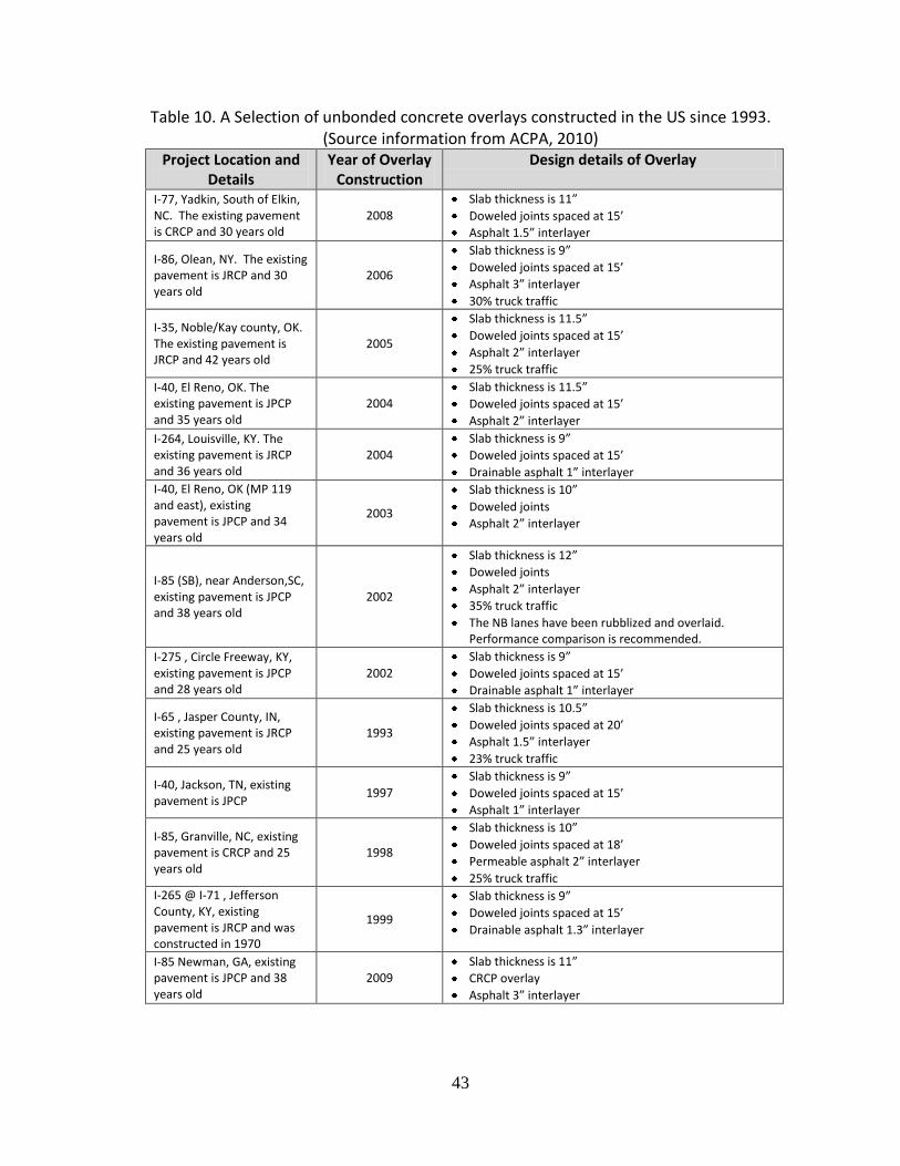
Example Designs
Table 10 summarizes a selection of unbonded concrete overlays of concrete pavements constructed in the US since 1993. The information presented in the table was compiled from National Concrete Overlay Explorer (a database provided by the American Concrete Pavement Association (ACPA, 2010)). The website currently contains only a representative sampling of projects across the US, and so the number of concrete overlay projects viewable online is expected to increase over time. The common features for these unbonded concrete overlays in Table 11 include:
Slab thickness ranges from 9 to 12 in.
Doweled joints spaced mostly at 15 ft.
HMA interlayers range in thickness from 1 to 3 in. with most dense-graded, but some open-graded mixes.
Existing pavements were either jointed or CRCP.

42
Summary for Unbonded Concrete Overlays of Concrete Pavements Based on the review of the best practices and performance of pavement sections in the LTPP database and related data in these best practices, the design recommendations for long lived unbonded concrete overlays are summarized in Table 11.
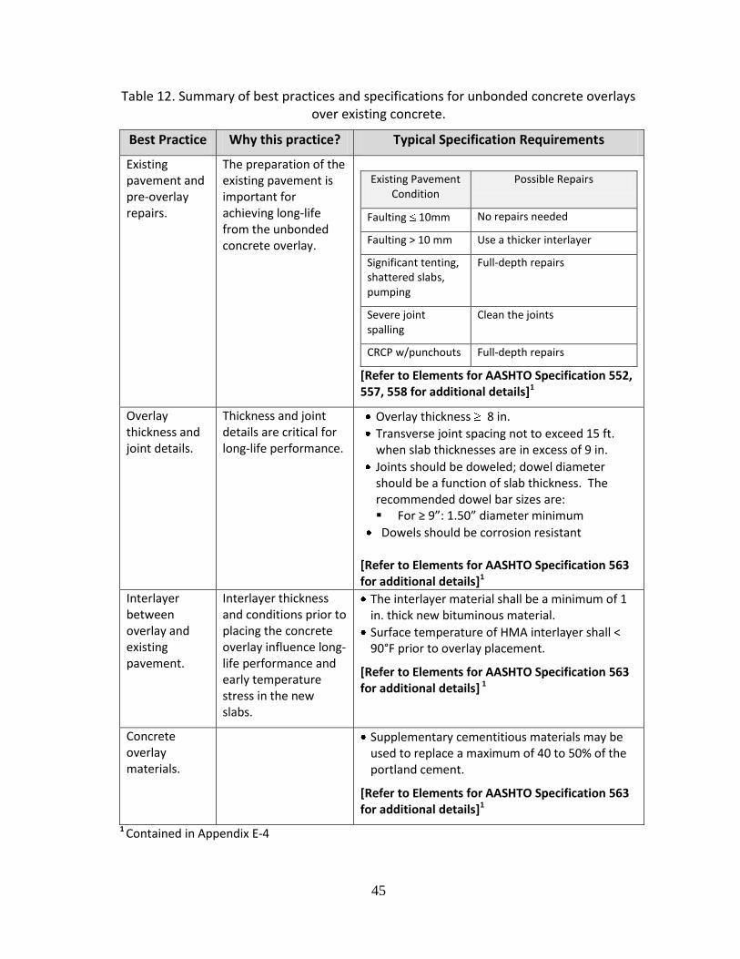
A selection of significant practices and specifications associated with paving unbonded concrete overlays over existing concrete were selected and included in Table 12. The table includes a brief explanation why the issue is of special interest, along with examples from the study guide specification recommendations. Three major practices are featured: (1) existing pavement and pre-overlay repairs, (2) overlay thickness and joint details, and (3) interlayer requirements.
Unbonded Concrete Overlay of Hot Mix Asphalt Concrete Pavements Criteria for Long-Life Potential
Unbonded concrete overlays of hot mix asphalt concrete (HMA) pavements are a viable long lived renewal strategy. In general, this strategy is applied when the existing HMA pavements exhibit significant deterioration in the form of rutting, fatigue cracking, potholes, foundation issues, and pumping; however, the stability and the uniformity of the existing pavement are important for both renewal construction and long life performance of the unbonded concrete overlay. Figure 33 is a sketch of an unbonded overlay over preexisting flexible pavement. The placement of the overlay can potentially (Smith et al (2002); Harrington (2008)):
Restore and/or enhance structural capacity of the pavement structure
Increase life equivalent to a full depth pavement
Restore and/or improve friction, noise and rideability
43
Table 10. A Selection of unbonded concrete overlays constructed in the US since 1993. (Source information from ACPA, 2010)
Project Location and Details
Year of Overlay Construction
Design details of Overlay
I-77, Yadkin, South of Elkin, NC. The existing pavement is CRCP and 30 years old
2008
Slab thickness is 11”
Doweled joints spaced at 15’
Asphalt 1.5” interlayer
I-86, Olean, NY. The existing pavement is JRCP and 30 years old
2006
Slab thickness is 9”
Doweled joints spaced at 15’
Asphalt 3” interlayer
30% truck traffic
I-35, Noble/Kay county, OK. The existing pavement is JRCP and 42 years old
2005
Slab thickness is 11.5”
Doweled joints spaced at 15’
Asphalt 2” interlayer
25% truck traffic
I-40, El Reno, OK. The existing pavement is JPCP and 35 years old
2004 Slab thickness is 11.5”
Doweled joints spaced at 15’
Asphalt 2” interlayer
I-264, Louisville, KY. The existing pavement is JRCP and 36 years old
2004 Slab thickness is 9”
Doweled joints spaced at 15’
Drainable asphalt 1” interlayer
I-40, El Reno, OK (MP 119 and east), existing pavement is JPCP and 34 years old
2003
Slab thickness is 10”
Doweled joints
Asphalt 2” interlayer
I-85 (SB), near Anderson,SC, existing pavement is JPCP and 38 years old
2002
Slab thickness is 12”
Doweled joints
Asphalt 2” interlayer
35% truck traffic
The NB lanes have been rubblized and overlaid. Performance comparison is recommended.
I-275 , Circle Freeway, KY, existing pavement is JPCP and 28 years old
2002
Slab thickness is 9”
Doweled joints spaced at 15’
Drainable asphalt 1” interlayer
I-65 , Jasper County, IN, existing pavement is JRCP and 25 years old
1993
Slab thickness is 10.5”
Doweled joints spaced at 20’
Asphalt 1.5” interlayer
23% truck traffic
I-40, Jackson, TN, existing pavement is JPCP
1997
Slab thickness is 9”
Doweled joints spaced at 15’
Asphalt 1” interlayer
I-85, Granville, NC, existing pavement is CRCP and 25 years old
1998
Slab thickness is 10”
Doweled joints spaced at 18’
Permeable asphalt 2” interlayer
25% truck traffic
I-265 @ I-71 , Jefferson County, KY, existing pavement is JRCP and was constructed in 1970
1999
Slab thickness is 9”
Doweled joints spaced at 15’
Drainable asphalt 1.3” interlayer
I-85 Newman, GA, existing pavement is JPCP and 38 years old
2009 Slab thickness is 11”
CRCP overlay
Asphalt 3” interlayer

44
Table 11. Recommended design attributes for LLCP (≥ 30 years).
Design Attribute Recommended Range
Overlay slab thickness Thickness ≥ 8 in. for ≥ 30 year life
Interlayer thickness (inches) ≥ 1 in.; 2 in. is likely optimal
Joint spacing Maximum spacing of 15 ft. Shorter is preferred (12 ft.)
Load transfer device Mechanical load transfer device, corrosion resistant dowels to promote long life. Dowel lengths of 18”
Dowel diameter 1.25 to 1.5 in. (function of slab thickness)
General Design Considerations The structural condition of the existing pavement can be established by conducting visual distress surveys and deflection testing using an FWD. The deflection information can be used to backcalculate the resilient moduli of various pavement layers (although HMA layers less than 3 in. thick are difficult to backcalculate).
Figure 33. Unbonded concrete overlay of flexible pavement. (Illustration: J. Mahoney)
45
Table 12. Summary of best practices and specifications for unbonded concrete overlays over existing concrete.
Best Practice Why this practice? Typical Specification Requirements
Existing pavement and pre-overlay repairs.
The preparation of the existing pavement is important for achieving long-life from the unbonded concrete overlay.
[Refer to Elements for AASHTO Specification 552, 557, 558 for additional details]1
Existing Pavement Condition
Possible Repairs
Faulting 10mm No repairs needed
Faulting > 10 mm Use a thicker interlayer
Significant tenting, shattered slabs, pumping
Full-depth repairs
Severe joint spalling
Clean the joints
CRCP w/punchouts Full-depth repairs
Overlay thickness and joint details.
Thickness and joint details are critical for long-life performance.
Overlay thickness 8 in.
Transverse joint spacing not to exceed 15 ft. when slab thicknesses are in excess of 9 in.
Joints should be doweled; dowel diameter should be a function of slab thickness. The recommended dowel bar sizes are: For ≥ 9”: 1.50” diameter minimum
Dowels should be corrosion resistant [Refer to Elements for AASHTO Specification 563 for additional details]1
Interlayer between overlay and existing pavement.
Interlayer thickness and conditions prior to placing the concrete overlay influence long-life performance and early temperature stress in the new slabs.
The interlayer material shall be a minimum of 1 in. thick new bituminous material.
Surface temperature of HMA interlayer shall < 90°F prior to overlay placement.
[Refer to Elements for AASHTO Specification 563 for additional details] 1
Concrete overlay materials.
Supplementary cementitious materials may be used to replace a maximum of 40 to 50% of the portland cement.
[Refer to Elements for AASHTO Specification 563 for additional details]1
1 Contained in Appendix E-4

46
Preoverlay Repairs
The preoverlay requirements are minimal at best. Table 13 summarizes the possible preoverlay repairs needed in preparation for the PCC unbonded concrete overlay of asphalt pavements (Harrington, 2008).
Table 13. Suggested preoverlay repairs. (Harrington, 2008)
Existing Pavement Condition Possible Repairs
Potholes Fill with asphalt concrete
Shoving Mill
Rutting 2” Mill
Rutting < 2” None or mill
Crack width 4” Fill with asphalt
Structural Design The design of an unbonded concrete overlay of HMA pavement considers the existing pavement as a stable and uniform base, and the overlay thickness is designed similarly to a new concrete pavement. Furthermore, the design assumes an unbonded condition between the existing asphalt layer and the new concrete overlay. The existing asphalt thickness should be at least 4 in. thick of competent material to ensure adequate load carrying base for the concrete overlay (Smith et al (2002); Harrington (2008)). The 1993 AASHTO design method does not consider the effects of bonding between the new overlay and the existing HMA pavement. The design method considers the composite k at the top of the HMA layer. Field studies have shown that there is some degree of bonding between the two layers. However, the longevity and the uniformity of this bond over the design life of the structure is not well documented. In the MEPDG design procedure the bonding between the two layers is modeled by selecting appropriate friction factors. In general (as documented in the literature), the unbonded overlay thickness usually ranges between 4 to 11 in., however, to ensure long life performance the slab thicknesses of the overlay should range between 8 to 13 in. The joint design, slab length, and joint width details are similar to unbonded concrete overlays of concrete pavements.

47
Performance Considerations
In general, the field performance of unbonded concrete overlays of HMA pavements has been satisfactory. The success of the renewal strategy hinges on the uniform underlying support. The underlying HMA base eliminates most of the pumping of fines so there is little to no faulting, and very uniform support. The general performance of PCC over HMA has been very good.
Example Designs
Table 14 summarizes unbonded concrete overlays of concrete pavements constructed in the United States since 1995. The information presented in the table was compiled from National Concrete Overlay Explorer. The website currently contains only a representative sampling of projects across the United States, and so the number of concrete overlay projects viewable online is expected to increase over time. The common features for these unbonded concrete overlays in Table 17 include:
Slab thicknesses range from 9 to 12 in.
Doweled joints spaced mostly at 15 ft.
Table 14 Overview of selected unbonded concrete overlays of flexible pavements constructed in the US since 1995 (Source data from ACPA, 2010)
Project Location and Details
Year of Overlay Construction
Design details of Overlay
Cherry Street, North to H-17, IA
2004 Slab thickness is 9” Doweled joints spaced at 15’
Tiger Mountain, OK, existing pavement was 9 years old
2004 Slab thickness is 10.5” Doweled joints spaced at 15’ 30% truck traffic
US 412, Bakervillie, MO. The existing is 30 years old
2004 Slab thickness is 12” Doweled joints spaced at 15’
24% truck traffic
US 412, Bakervillie, MO.
2003 Slab thickness is 12” Doweled joints spaced at 15’ 24% truck traffic
I-55, Vaiden, MS 2001 Slab thickness is 10” Doweled joints spaced at 16’
E-33, IA 1998 Slab thickness is 9” Doweled joints spaced at 15’
P-33, IA 1998 Slab thickness is 10” Doweled joints spaced at 15’
I-10/1-12, LA 1995 Slab thickness is 12”
48
Added Lanes and Transitions for Adjacent Structures for Unbonded PCC Overlays over Existing Concrete and HMA Pavements There is little guidance found in the literature on integrating new or rehabilitated pavements into adjacent pavements and features. This document addresses adding lanes to an existing pavement structure, as well as accommodating existing features such as bridge abutments and vertical clearance restrictions within the limits of a pavement renewal project. These issues are paramount when using the existing pavement in-place as part of long-life renewal, because there is typically a significant elevation change associated with each renewal alternative. The following recommendations are based on discussions with the SHAs surveyed in Phase 1 and those Agencies who participated in Phase 2.
Bridge and Overcrossing Structure Approaches In the transition where the unbonded PCC overlay connects to a bridge approach, or when the roadway section with an unbonded overlay passes under an existing structure, the new grade line and reduced vertical clearances usually require the construction of a new pavement section. The length of the new section depends upon the elevation difference, but is usually in the range of 300 to 500 ft. before and after the structure. A typical taper rate used by a number of Agencies visited is 400 to 1 to transition from the new grade line to the elevation required by the adjacent feature. Attention should be paid to the longitudinal drainage as well as the transverse drainage when designing the new pavement section. Where possible, the existing subgrade elevation and grade should be maintained in the longitudinal direction as well as the transverse direction. Because the new roadway section will not be as thick as the renewal approach using the existing pavement, the difference in elevation is usually made up with HMA or a combination of HMA and untreated granular base material. Since the unbonded PCC overlay requires reasonably uniform support, the transition from the old PCC pavement to the new pavement should be made as stiff as possible, which may require replacement of the PCC with full depth HMA. Subgrade stabilization should also be considered if needed in the transition area. Specifically, the SHRP 2 guidance for "Geotechnical Solutions for Transportation Infrastructure" and their recommendations for stabilization of the pavement working platform should be considered. Diagrams of possible transition profiles are shown in Figures 34 and 35.
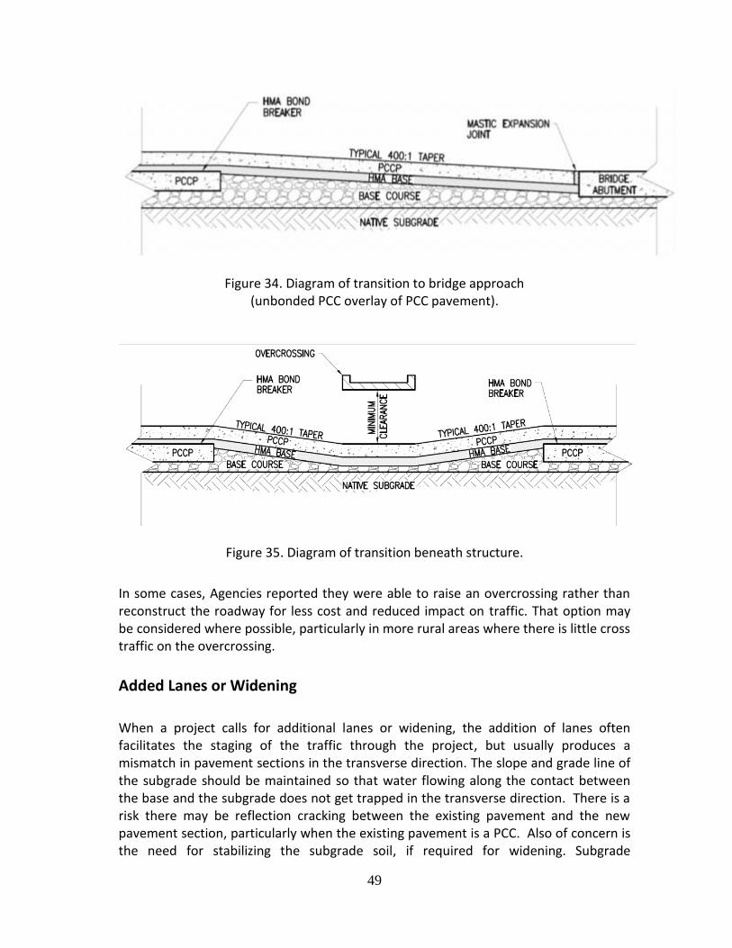
49
Figure 34. Diagram of transition to bridge approach (unbonded PCC overlay of PCC pavement).
Figure 35. Diagram of transition beneath structure.
In some cases, Agencies reported they were able to raise an overcrossing rather than reconstruct the roadway for less cost and reduced impact on traffic. That option may be considered where possible, particularly in more rural areas where there is little cross traffic on the overcrossing.
Added Lanes or Widening
When a project calls for additional lanes or widening, the addition of lanes often facilitates the staging of the traffic through the project, but usually produces a mismatch in pavement sections in the transverse direction. The slope and grade line of the subgrade should be maintained so that water flowing along the contact between the base and the subgrade does not get trapped in the transverse direction. There is a risk there may be reflection cracking between the existing pavement and the new pavement section, particularly when the existing pavement is a PCC. Also of concern is the need for stabilizing the subgrade soil, if required for widening. Subgrade

50
stabilization will increase the stability of the roadway section, accelerate pavement construction, and help reduce some of the settlement or differential vertical deflection that causes reflection cracking along the contact with the old PCC pavement. Specifically, the SHRP 2 guidance for "Geotechnical Solutions for Transportation Infrastructure" and their recommendations for stabilization of the pavement working platform should be considered.
Lane Widening A number of Agencies have reported they have constructed a 14 ft. widened lane in the outside lane to provide improved edge support. One Agency reported cracking along the edge of the old PCC pavement caused by non-uniform support at that location. They had not improved the shoulder section prior to construction of the unbonded PCC overlay. If lane widening is considered, the existing shoulder section may need to be reconstructed to provide more uniform support for the new PCC pavement.
Added Lanes When a project calls for additional lanes or widening, the addition of lanes often facilitates the staging of the traffic through the project, but usually produces a mismatch in pavement sections in the transverse direction. The slope and grade line of the subgrade should be maintained so that water flowing along the contact between the base and the subgrade does not get trapped in the transverse direction. Similar to widened lanes, there is a need for uniform support under the PCC overlay, thus the shoulder will need to be reconstructed and the subgrade should be stabilized where needed.
No specific guidance could be found to provide uniform support in the widening next to the existing PCC pavement. A number of Agencies have widened with HMA as part of the traffic staging, and then placed the unbonded PCC pavement across both the existing PCC pavement with a HMA bond breaker, and the widened HMA pavement. Some Agencies have widened the existing PCC pavement with PCC pavement, then placed the HMA bond-breaker across both the old and new PCC pavement before placing the PCC overlay. This approach provides uniform support for the PCC overlay; however, there was no indication that there was any difference in performance when the widening was constructed with PCC pavement or HMA pavement as a base for the PCC overlay. Use of HMA to widen the existing pavement does provide some advantage in traffic staging. Typical pavement sections are shown in Figures 36 and 37. The minimum thickness of the HMA in the widening is usually controlled by the traffic loading during staging, but is usually a minimum of 6 in. thick, to minimize failure risk during staging and provide more uniform support for the PCC overlay.

51
Figure 36. Cross section showing existing PCC pavement without daylighted shoulders.
Figure 37. Cross section showing widening of the shoulder with daylighting or drainage. For unbonded PCC overlays of flexible pavement the existing pavement is simply widened with HMA to provide the base for the PCC overlay. The pavement section should extend the subgrade line and slope out to either the contact with the in-slope of the ditch or fill slope, or to a collection point for longitudinal drains as shown in Figures 37 and 38.

52
Figure 38. Cross section detail with PCC shoulder.
Best Practices Summary The definition of long life renewal strategies is a design life ≥ 30 years. To achieve this, unbonded concrete overlays of existing pavements are recommended. This recommendation is based on several sets of information which includes but is not limited to (1) State DOT criteria, (2) LTPP findings, and (3) information from the National Concrete Pavement Technology Center. To achieve a 30 to 50 year life, several practices are critical, and these include the selection of materials, knowledge of local pavement distress and its causes, structural design and relevant construction practices. Two broad types of unbonded concrete were discussed: (1) unbonded concrete over existing concrete pavement and (2) unbonded concrete over existing HMA pavement. Concrete overlays can be either JPCP or CRCP—both perform well. Included is a summary of relevant best practices and related specification requirements (Table 11). Three major practices are featured: (1) existing pavement and pre-overlay repairs, (2) overlay thickness and joint details, and (3) interlayer requirements. The major findings are recapped in Table 15.
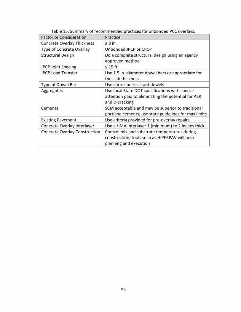
53
Table 15. Summary of recommended practices for unbonded PCC overlays.
Factor or Consideration Practice
Concrete Overlay Thickness ≥ 8 in.
Type of Concrete Overlay Unbonded JPCP or CRCP
Structural Design Do a complete structural design using an agency approved method
JPCP Joint Spacing ≤ 15 ft.
JPCP Load Transfer Use 1.5 in. diameter dowel bars or appropriate for the slab thickness
Type of Dowel Bar Use corrosion resistant dowels
Aggregates Use local State DOT specifications with special attention paid to eliminating the potential for ASR and D-cracking
Cements SCM acceptable and may be superior to traditional portland cements; use state guidelines for max limits
Existing Pavement Use criteria provided for pre-overlay repairs.
Concrete Overlay Interlayer Use a HMA interlayer 1 (minimum) to 2 inches thick.
Concrete Overlay Construction Control mix and substrate temperatures during construction; tools such as HIPERPAV will help planning and execution

54
References
ACPA (1990), “Guidelines for Unbonded Concrete Overlays,” Technical Bulletin 005.0D, American Concrete Pavement Association. ACPA (2006), “Pavement Surface Characteristics – A Synthesis and Guide”, American Concrete Pavement Association, Skokie, IL, 2006. ACPA (2010), “The National Concrete Overlay Explorer,” American Concrete Pavement Association, http://overlays.acpa.org/webapps/overlayexplorer/index.html Anderson, K., Uhlmeyer, J., Pierce, L. and Weston, J. (2006), “ Wear Resistant Pavement Study,” Report WA-RD 657.1, Washington State Department of Transportation, October 2006. Applied Pavement Technology (2002), “Unbonded Portland Cement Concrete Overlays,” Publication No. FHWA-IF-03-006, Federal Highway Administration, May 2002. ARA (2004), “Guide for Mechanistic-Empirical Design of New and Rehabilitated Pavement Structures,” Final Report, Part 2 Design Inputs, Chapter 2 Material Characterization, National Cooperative Highway Research Program, March 2004. AASHTO (1993), “AASHTO Guide for Design of Pavement Structures,” American Association of State Highway and Transportation Officials. AASHTO (2010), “Provisional Practice for Determining the Reactivity of Concrete Aggregates and Selecting Measures for Preventing Deleterious Expansion in New Concrete Construction” PP 65-10, Provisional Standards, 14th Edition, American Association of State Highway and Transportation Officials. Burnham, T. (2008), “Thin and Ultra-Thin Concrete Overlays,” MnRoad Lessons Learned, Office of Materials, Minnesota Department of Transportation, February 8, 2008. CP Tech Center (2011), “Guide to Dowel Load Transfer Systems for Jointed Concrete Pavements”, National Concrete Consortium, National Concrete Pavement Technology Center, Iowa State University, Ames, IA, 2011. EPA (2011), “Resource Conservation - Comprehensive Procurement Guidelines,” Environmental Protection Agency, January 5, 2011. http://www.epa.gov/epawaste/conserve/tools/cpg/about.htm

55
ERES (1999), “Evaluation of Unbonded Portland Cement Concrete Overlays,” NCHRP Report No. 415, Transportation Research Board, 1999. Farney, J. and Kosmatka, S. (1997), “Diagnosis and Control of Alkali-Aggregate Reactions in Concrete,” IS 413, Concrete Information, Portland Cement Association, Skokie, Illinois. FHWA (2005), “Use of Magnetic Tomography Technology to Evaluate Dowel Bar Placement,” Report FHWA-IF-06-002, Federal Highway Administration, October 2005. FHWA (2006), “High Performance Concrete Pavements—Project Summary,” Publication No. FHWA-IF-06-031, Federal Highway Administration, February 2006. FHWA (2007), “Best Practices for Dowel Placement Tolerances,” Report FHWA-HIF-07-021, Federal Highway Administration, June 2007. Folliard, K. and Smith, K. (2003), “Aggregate Tests for Portland Cement Concrete Pavements: Review and Recommendations,” Number 281, Research Result Digest, National Cooperative Highway Research Program, September 2003. Fournier, B., Berube, M., Folliard, K., Thomas, M. (2010), “Report on the Diagnosis, Prognosis, and Mitigation of Alkali-Silica Reaction (ASR) in Transportation Structures,” Report FHWA-XXX-XX-XX, Office of Pavement Technology, Federal Highway Administration, January 2010. Germann Instruments, Inc, “Eddy-Dowel,” Evanston, Illinois. Accessed July 2011. www.germann.org/TestSystems/Eddy-Dowel/Eddy-Dowel.pdf Harrington, D. (2008), “Guide to Concrete Overlays-Sustainable Solution for Resurfacing and Rehabilitating Existing Pavements,” 2nd Edition, National Concrete Pavement Technology Center, Ames, Iowa, September 2008 HIPERPAV (2010), “HIPERPAV High Performance Paving Software,” Version 3.20.0006, The Transtec Group and the Federal Highway Administration, http://www.hiperpav.com/
Kim, DH, Choi, SC, Cho, YH, Won, MC (2007), “Long Term Performance of Thin Bonded Concrete Overlay in Texas,” Paper No. 07-0031, Transportation Research Board. Kim, DH, Fowler, DW, Ferron, RP, Trevino, MM, Whitney, DP (2012), “Materials Selection for Concrete Overlays“, Final Report FHWA/TX-11/0-6590-2, Texas DOT, published July 2012. McGhee, K. (1994), “Portland Cement Concrete Resurfacing,” Synthesis of Highway Practice 204, National Cooperative Research Program, Transportation Research Board.

56
Miner, M. (1945), “Cumulative Damage in Fatigue,” Transactions, Vol. 67, American Society of Mechanical Engineers. Missouri DOT (1998), “SHRP LTPP Test Sections,” Research Investigation 91-001, Research, Development, and Technology Division, Missouri Department of Transportation, September 1998. Missouri DOT (2002), “Missouri Guide for Pavement Rehabilitation,” Report RDT 02-013, Research, Development, and Technology Division, Missouri Department of Transportation, November 2002. MnDOT (2005a), “Standard Specifications for Road, Bridge, and Municipal Construction,” Minnesota Department of Transportation. MnDOT (2005b), “S114 – (2301) High Performance Concrete Pavement – Dowel Bar”, Special Provisions, Minnesota Department of Transportation, St. Paul, MN. MnRoad (2009), “Whitetopping: Concrete Overlays of Asphalt Pavements,” Version 1, Minnesota Department of Transportation, June 2009. Neville, A. (1975), “Properties of Concrete,” John Wiley and Sons, New York. Packard, R. (1973), “Design of Concrete Airport Pavement,” Engineering Bulletin, Portland Cement Association. Packard, R. (1995), “Thickness Design for Concrete Highway and Street Pavements,” Engineering Bulleting, Portland Cement Association. Rasmussen, R., Garber, S., Fick, G., Ferragut, T., and Wiegard, P. (2008), “How to Reduce Tire-Pavement Noise: Interim Better Practices for Constructing and Texturing Concrete Pavement Surfaces,” Pooled Fund TPF-5(139) PCC Surface Characteristics: Tire-Pavement Noise Program Part 3—Innovative Solution/Current Practices, Federal Highway Administration, July 2008. Rasmussen, R. and Rozycki, D. (2004), “Thin and Ultra-Thin Whitetopping—A Synthesis of Highway Practice,” Synthesis 338, National Cooperative Highway Research Program, Transportation Research Board. Richardson, D. (2005), “Aggregate Gradation and Optimization—Literature Search,” Report RDT 05-001, Missouri Department of Transportation, January 2005. Smith, K., Yu, H., and Peshkin, D. (2002), “Portland Cement Concrete Overlays: State of the Technology Synthesis,” Report No. FHWA IF-02-045, Federal Highway Administration, April 2002.

57
Smith, T. and Tayabji, S. (1998), “Assessment of the SPS-7 Bonded Concrete Overlays Experiment,” Final Report, FHWA-RD-98-130, Office of Engineering Research and Development, Federal Highway Administration, September 1998. Tayabji, S. and Lim, S. (2007), “Long Life Concrete Pavements: Best Practices and Directions from the States,” Concrete Pavement Technology Program, Tech Brief, FHWA-HIF-07-030, July 2007. Tayabji, S, Gisi, A., Blomberg, J. and DeGraaf, D. (2009), “New Applications for Thin Concrete Overlays: Three Case Studies,” National Conference on PRR of Concrete Pavements, St. Louis, April 2009. TxDOT (2008), “Chapter 8. Thin Concrete Overlays” and “Table 8-4: Thin Whitetopping Thickness Design,” Pavement Design Manual, Texas Department of Transportation, November 1, 2008. TxDOT (2011), “Chapter 10—Rigid Pavement Rehabilitation, Section 4—Bonded Concrete Overlays,” Pavement Design Manual, Texas Department of Transportation, January 2011. Thomas, M., Fournier, B., Folliard, K. (2008), “Report on Determining the Reactivity of Concrete Aggregates and Selecting Appropriate Measures for Preventing Deleterious Expansion in New Concrete Construction,” Report FHWA-HIF-09-001, Office of Pavement Technology, Federal Highway Administration, April 2008. TxDOT (2009a), “Continuously Reinforced Concrete Pavement—One Layer Steel Bar Placement,” Design Division Standard, Texas Department of Transportation, November 2009. TxDOT (2009b), “Continuously Reinforced Concrete Pavement—Two Layer Steel Bar Placement,” Design Division Standard, Texas Department of Transportation, November 2009. TxDOT (2011), “Section 5: Determining Concrete Pavement Thickness,” Pavement Design Guide, Texas Department of Transportation, January 1, 2011. Van Dam, T., Sutter, L, Smith, D., Wade, M., K. R. Peterson, K. (2002) “Guidelines for Detection, Analysis, and Treatment of Material Related Distresses in Concrete Pavements,” Volume 1: Final Report, FHWA –RD-01-163, August 2002. Wisconsin DOT (2009), “HPC Pavement Requirements for Concrete Pavement 12-inch”. Special Provisions, Wisconsin Department of Transportation, Madison, WI. February 2009.
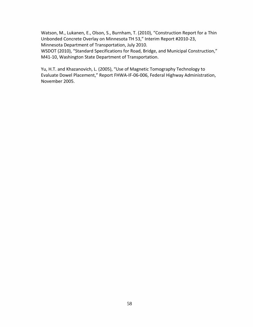
58
Watson, M., Lukanen, E., Olson, S., Burnham, T. (2010), “Construction Report for a Thin Unbonded Concrete Overlay on Minnesota TH 53,” Interim Report #2010-23, Minnesota Department of Transportation, July 2010. WSDOT (2010), “Standard Specifications for Road, Bridge, and Municipal Construction,” M41-10, Washington State Department of Transportation. Yu, H.T. and Khazanovich, L. (2005), “Use of Magnetic Tomography Technology to Evaluate Dowel Placement,” Report FHWA-IF-06-006, Federal Highway Administration, November 2005.

59
Supplemental Documentation Concrete Overlays—Supporting Data and Practices
Given the initial definition of long life renewal strategies and the constraints of life expectancy associated with timing and selection of pavement renewal strategies, the early findings of this study recommended that only unbonded concrete overlays (using HMA separator layers) of existing concrete and asphalt pavements are likely to perform adequately for 50 or more years. This conclusion was based on several sets of information which includes, but is not limited to, (1) prior pavement design criteria, (2) State DOT criteria and field projects, (3) LTPP findings, (4) state field visits, and (5) information from the National Concrete Pavement Technology Center (Harrington, 2008). When the definition of long life pavement was reduced to include pavements lasting 30 or more years, bonded and thinner concrete overlays required reexamination. It is and has been apparent that slab thickness is a major factor in long life renewal options. Well known design procedures for PCC systems have been available for several decades. For example, Packard (1973) used fatigue concepts for airport pavement design for the Portland Cement Association (PCA). Packard and Neville (1975) both noted that for flexural stress ratios less than 0.55 (applied flexural stress/modulus of rupture), the fatigue life of PCC is unlimited. Packard actually used a stress ratio of 0.50 to add a bit of conservatism to the PCA airfield design process. Additionally, Packard (1984, 1995) produced a fatigue-based highway design method for the PCA. This method is also based on fatigue principles (specifically, the flexural stress is divided by the modulus of rupture [28 day cure]). These fatigue-based approaches use Miner’s hypothesis (Miner, 1945) for accumulating fatigue damage. In addition to existing design procedures and State DOT practices, an extensive amount of pavement performance data has been collected over the last 20 years via the Long Term Pavement Performance (LTPP) program. These results, as relevant to long life rigid renewal best practices are summarized as follows.
Long-Term Pavement Performance (LTPP) and State DOT Information
LTPP LTPP results were examined to see what could be learned about long-life designs. This included data from GPS-9 and SPS-7 projects. Unbonded Concrete Overlays. From the GPS-9 experiment (Unbonded Concrete Overlays, which included unbonded JPCP or CRCP overlays placed on JPCP or CRCP), performance data reviewed for Phase I of this study was used. The overlay thicknesses ranged from 5.8 to 10.5 in. Separator layers included dense-graded asphalt concrete,
60
open-graded asphalt concrete, and chip seals. The average joint spacing was about 16 ft. and load transfer mechanisms either aggregate interlock or steel dowels. A summary of the sections and major findings from that assessment include:
Of the unbonded overlays reviewed, the thicknesses were:
o 6 in. thick: 22%
o 8 in. thick: 22%
o 9 in. thick: 11%
o 10 in. thick: 45%
The thicker JPCP overlays (≥ 8 in.) exhibited essentially no transverse cracks. The
CRCP overlays had transverse cracks with 4 ft. spacing for overlays < 10 in. thick
and 5 ft. spacing for overlays 10 in. thick.
On average, thicker GPS-9 overlays had lower IRI values.
The overall magnitude of the faulting was well below 0.25 in. for all unbonded overlays (the threshold considered for long life pavements). Faulting levels were
significantly less for (1) thicker slabs ( 10 in. thick), (2) interlayer thicknesses 2 in., and (3) use of HMA as the interlayer material.
Thicker HMA interlayers appear to inhibit transverse cracking. It also contributed towards the integrity of the joint by controlling the amount of joint faulting.
Use of dowel bars in transverse joints had a positive impact on all pavement performance measures.
Bonded Concrete Overlays. From the SPS-7 experiment (Bonded Concrete Overlays on PCC Pavement), these sections were examined for Phase I of this study and included three types of bonded overlays: JPCP, CRCP, and Plain Concrete Pavement (PCP). The third type of overlay included PCP, which was placed on existing CRCP but without reinforcement in the overlay. The ages of overlays ranged between 7 to 11 years (the time between construction and the last condition survey). The overlay thicknesses of the various test sections ranged from a minimum of 3.1 in. to a maximum of 6.5 in. The bonding agent type used in 21 of the SPS-7 sections was water/cement grout, and in 13 sections no bonding agents were employed. The surface preparation methods used to create bond in the various sections included shot blasting, water blasting, and milling. The major findings from that assessment follow.
Of these overlays located in four states, the total number of sections (35) expressed as percentages associated by overlay type are: o CRCP: 51% o JPCP: 26% o PCP: 23%
For bonded JPCP overlays, eight sections all were located on Route 67 in Missouri—which, at the time of construction (1990), experienced about 250,000 ESALs/year. The JPCP overlays ranged in thickness from 3.0 in. to 5.4 in. (see below) with an average of 4.3 in. These overlays were placed on existing JPCP which had a 20 ft.

61
spacing between transverse joints. Prior to placing the bonded overlays two surface preparation treatments were used: either shot blasting or milling. All of these SPS sections had a length of 500 ft. The actual overlay thicknesses and performance with respect to transverse cracks five years following construction are shown in Table 1.
Table 1. Overlay thickness and performance over five years.
Target Overlay Thickness (in.)
Overlay Thickness (in.) based on cores
No. Transverse Cracks Prior to Overlay
(JCPC constructed in 1955, 10 in. slabs)
No. of Transverse Cracks 5 years
After Construction
3.0 4.4 1 21
3.0 3.0 0 11
3.0 3.6 9 43
3.0 3.0 0 15
5.0 4.8 6 102
5.0 4.9 3 101
5.0 5.2 2 94
5.0 5.4 4 130
Sources: (1) Smith and Tayabji, 1998, and (2) Missouri DOT, 1998.
The cracking levels observed for these nominal 3 and 5 in. thick bonded overlays suggest that these sections will not serve adequately for 30 to 50 years. The Missouri DOT notes in their Guide for Pavement Rehabilitation (2002): “(1) A bonded PCC overlay is a viable rehabilitation treatment that has historically been technically difficult to construct properly, and (2) unbonded PCC overlays should provide at least 20 years of good performance if properly designed and constructed. PCC thickness should be ≥ 8 inches with an AC interlayer ≥ 1 inch.” Thus, use of bonded overlays is allowed but unbonded overlays are preferred with 8 in. or thicker slabs.
The CRCP overlays ranged in thickness from 3.2 in. to 6.5 in. with an average of 4.6 in. All of these overlays were placed on existing CRCP.
The CRCP overlays show more promise in that only 4 of 19 sections in the SPS-7 experiment exhibited punchouts following 5 to 7 years of service; however, the length of service precludes a clear view about longevity.
The data suggest that on average, thicker SPS-7 overlays (> 6 in.) resulted in lower IRI values.
Given the performance of the LTPP JPCP bonded concrete overlays in Missouri and the amount of cracking observed, it appears long life concrete overlays for a 30 to 50 year life is only likely for thicker unbonded overlays. This is further supported by additional state experience, which follows. The remainder of this supplemental documentation will continue to explore largely the performance of bonded concrete overlays and
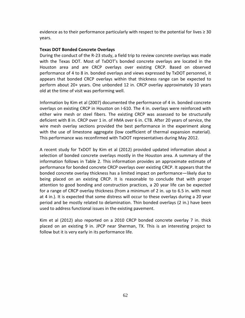
62
evidence as to their performance particularly with respect to the potential for lives ≥ 30 years. Texas DOT Bonded Concrete Overlays During the conduct of the R-23 study, a field trip to review concrete overlays was made with the Texas DOT. Most of TxDOT’s bonded concrete overlays are located in the Houston area and are CRCP overlays over existing CRCP. Based on observed performance of 4 to 8 in. bonded overlays and views expressed by TxDOT personnel, it appears that bonded CRCP overlays within that thickness range can be expected to perform about 20+ years. One unbonded 12 in. CRCP overlay approximately 10 years old at the time of visit was performing well. Information by Kim et al (2007) documented the performance of 4 in. bonded concrete overlays on existing CRCP in Houston on I-610. The 4 in. overlays were reinforced with either wire mesh or steel fibers. The existing CRCP was assessed to be structurally deficient with 8 in. CRCP over 1 in. of HMA over 6 in. CTB. After 20 years of service, the wire mesh overlay sections provided the best performance in the experiment along with the use of limestone aggregate (low coefficient of thermal expansion material). This performance was reconfirmed with TxDOT representatives during May 2012. A recent study for TxDOT by Kim et al (2012) provided updated information about a selection of bonded concrete overlays mostly in the Houston area. A summary of the information follows in Table 2. This information provides an approximate estimate of performance for bonded concrete CRCP overlays over existing CRCP. It appears that the bonded concrete overlay thickness has a limited impact on performance—likely due to being placed on an existing CRCP. It is reasonable to conclude that with proper attention to good bonding and construction practices, a 20 year life can be expected for a range of CRCP overlay thickness (from a minimum of 2 in. up to 6.5 in. with most at 4 in.). It is expected that some distress will occur to these overlays during a 20 year period and be mostly related to delamination. Thin bonded overlays (2 in.) have been used to address functional issues in the existing pavement. Kim et al (2012) also reported on a 2010 CRCP bonded concrete overlay 7 in. thick placed on an existing 9 in. JPCP near Sherman, TX. This is an interesting project to follow but it is very early in its performance life.
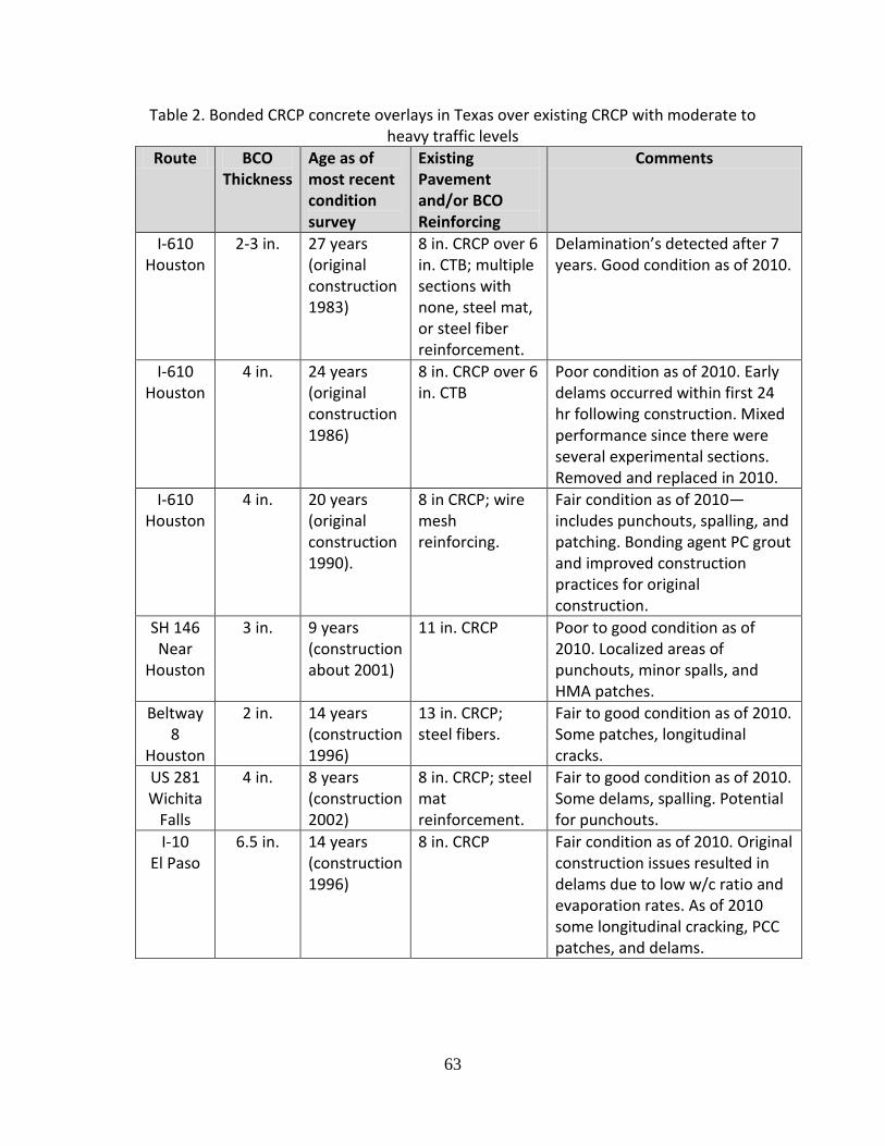
63
Table 2. Bonded CRCP concrete overlays in Texas over existing CRCP with moderate to heavy traffic levels
Route BCO Thickness
Age as of most recent condition survey
Existing Pavement and/or BCO Reinforcing
Comments
I-610 Houston
2-3 in. 27 years (original construction 1983)
8 in. CRCP over 6 in. CTB; multiple sections with none, steel mat, or steel fiber reinforcement.
Delamination’s detected after 7 years. Good condition as of 2010.
I-610 Houston
4 in. 24 years (original construction 1986)
8 in. CRCP over 6 in. CTB
Poor condition as of 2010. Early delams occurred within first 24 hr following construction. Mixed performance since there were several experimental sections. Removed and replaced in 2010.
I-610 Houston
4 in. 20 years (original construction 1990).
8 in CRCP; wire mesh reinforcing.
Fair condition as of 2010—includes punchouts, spalling, and patching. Bonding agent PC grout and improved construction practices for original construction.
SH 146 Near
Houston
3 in. 9 years (construction about 2001)
11 in. CRCP Poor to good condition as of 2010. Localized areas of punchouts, minor spalls, and HMA patches.
Beltway 8
Houston
2 in. 14 years (construction 1996)
13 in. CRCP; steel fibers.
Fair to good condition as of 2010. Some patches, longitudinal cracks.
US 281 Wichita
Falls
4 in. 8 years (construction 2002)
8 in. CRCP; steel mat reinforcement.
Fair to good condition as of 2010. Some delams, spalling. Potential for punchouts.
I-10 El Paso
6.5 in. 14 years (construction 1996)
8 in. CRCP Fair condition as of 2010. Original construction issues resulted in delams due to low w/c ratio and evaporation rates. As of 2010 some longitudinal cracking, PCC patches, and delams.

64
The Texas Pavement Design Guide (January 2011) provides additional insight on bonded concrete overlays. The Guide states that bonded concrete overlays placed over thin existing concrete pavement must behave as a monolithic layer. Further, TxDOT has constructed bonded concrete overlays ranging in thickness from 2 to 8 in. thick. Bonded concrete overlays have not performed well over existing JPCP. Conversely, bonded CRCP overlays over existing CRCP have performed successfully in several districts but have not been used widely throughout the state. A portion of that chapter follows: From Chapter 10—Rigid Pavement Rehabilitation, Section 4—Bonded Concrete Overlay (TxDOT Pavement Design Guide):
“This chapter describes bonded concrete overlays (BCO) on continuously reinforced concrete pavement (CRCP), not on concrete pavement contraction design (CPCD). BCO is not a good option for the rehabilitation of CPCD. In the past, concrete pavements were designed and constructed with insufficient thicknesses for today’s traffic demand. This insufficient thickness often resulted in pavement distresses such as punchouts for CRCP and mid-slab cracking or joint faulting in CPCD. If the Portland cement concrete (PCC) pavement is structurally sound (in other words, if the slab support is in good condition) except for the deficient thickness, BCO can provide cost-effective rehabilitation strategies to extend the pavement life. In bonded concrete overlays, new concrete layer is applied to the surface of the existing PCC pavement. This increases the total thickness of the concrete slab, thereby reducing the wheel load stresses and extending the pavement life. There are BCO projects in Texas that have provided an additional 20 yr. of service. At the same time, there are BCO projects that did not perform well. The difference between good and poorly performing BCOs is the bond strength between new and old concretes. The critical requirement for the success of BCO is a good bond between a new and old concrete layers. If a good bond is provided, the new slab consisting of old and new concrete layers will behave monolithically and increased slab thickness. The increased slab thickness will reduce the wheel load stress at the bottom of the slab substantially, prolonging the pavement life. On the other hand, if a sufficient bond is not provided, the wheel load stress level in the new concrete layer will be high and the pavement performance will be compromised. If the overlay is being placed only to remedy functional failures, normally a thinner overlay would suffice. However, 2 in. is the minimum practical constructible thickness for an overlay. For the steel design, when the overlay thickness is more than 40% of the existing CRCP, longitudinal steel should be provided for the overlay. If the steel is not provided:

65
The longitudinal steel in the existing CRCP will be in much higher stress, diminishing its ability to restrain concrete volume changes
The distance between the overlaid concrete surface and the existing steel will be increased and the ability of the existing steel to control the concrete volume changes at the surface will be diminished, resulting in more concrete volume changes and larger crack widths at the surface. The amount of steel needed should be sufficient to control the overlaid concrete volume changes. The guidelines to be developed in the current research study are expected to address steel design.
Steel should be placed at a depth that provides a minimum concrete cover of 3 in. If the overlaid thickness layer is not large enough, reinforcement steel bars can be placed directly over the surface of the existing pavement as shown in Figure 10-11 [see referenced TxDOT document], rather than at mid-depth of the overlay. For overlaid thickness that is not large enough, it may not be feasible to use a slip-form paving machine to place steel at the mid-depth of the overlay due to the use of vibrators. Placing steel directly on top of the surface of the existing pavement has advantages and disadvantages. Advantages include: saving construction time and costs, since it does not require chairs. Another advantage: the steel will restrain concrete volume changes at the interface most effectively, which will prevent or retard debonding. The only disadvantage is the reduction of the interface area between the new and old concrete. Taken together, for overlaid thickness up to about 5 in., placing steel on top of the existing concrete appears to be a better construction practice. A research study currently underway will address this issue. Guidelines will include recommendations.”
Washington State DOT Bonded Concrete Overlays Bonded JPCP concrete overlays constructed in 2003 over existing HMA were reviewed (Figure 1). Three thicknesses of concrete overlays were used: 3, 4, and 5 in. each placed on I-90 east of Spokane, WA which experiences about 1,000,000 ESALs/year. These sections were removed during 2011 due to pavement reconstruction, thus they were in-service for 8 years.

66
Construction of bonded PCC overlays in July 2003 which were placed directly on rotomilled HMA.
Figure 1. Construction of bonded PCC overlays in Washington State. (Photos: WSDOT) Each of the bonded concrete overlays was 500 ft. long and used the same PCC mix. Transverse contraction joints were sawed at 5 ft. spacings and the longitudinal joint split the 12 ft. wide lane (thus a joint spacing of 5 ft by 6 ft.) as illustrated in Figure 2. The mix had a specified minimum flexural strength of 800 psi with a minimum cement content of 800 lb per yd3. Polypropylene fibers were added at a rate of 3 lb per yd3. A carpet drag finish was applied to the surface (Andersen et al, 2006). The underlying HMA thicknesses were 9 in. for the 3 in. slab, 8 in. of the 4 in. slab, and 7 in. for the 5 in. slab. Following one year of service, cracking in the three bonded JPCP sections were:
87 percent of the 3 in. thick panels were cracked.
Each of 4 and 5 in. sections had 4 percent cracked panels. At the time of removal in 2011 (Figure 3), the 3 in. section was severely distressed as shown in Figure 2. The 4 and 5 in. thick sections were in substantially better condition. The total accumulated ESALs at the time of removal were a bit less than 10 million.

67
3 in. Bonded PCC overlay of HMA following 8 years of service.
Figure 2. Condition of 3 in. bonded overlay in 2011. (Photos: WSDOT)
Removal of 3 in. PCC overlay prior to reconstruction of this portion of I-90
Figure 3. Bond between the PCC overlays were assessed visually during removal in
2011. (Photo: WSDOT) Minnesota DOT Unbonded and MnRoad Bonded Concrete Overlays During March 2012, the study team made an additional visit to the Minnesota DOT. The purpose was to review the study guidelines and performance of their unbonded and bonded concrete overlays. An example of the performance of one of their unbonded concrete overlays is shown in Figure 4. Discussion with the MnDOT pavement team suggested that this type of overlay is expected to perform for 25 to 30 years. Given the specific section shown in Figure 4, this section on I-35 at MP 156 (north of Minneapolis) was 25 years old at the

68
time of the site visit. The transverse contraction joints were doweled, skewed, and placed 15 ft. apart. It was placed over a pre-existing JRCP pavement. It is reasonable to expect this section to perform beyond a 30 year life given its excellent condition (no observed cracking or faulting).
Unbonded 8 in. overlay over pre-existing JRCP on I-35 in Minnesota. The transverse joints are spaced at 15 ft. with dowels. The photos were taken during March 2012 and the section was 25 years old at that time.
Figure 4. Condition of 8 in. unbonded concrete overlay on I-35 in Minnesota. (Photos: J. Mahoney)
The primary Minnesota experience with bonded concrete overlays is at the MnRoad facility. They constructed the first set of bonded JPCP concrete overlays on existing HMA at MnRoad in 1997, which included 3, 4, and 6 in. thick sections. Following 7 years of service, the 3 and 4 in. thick sections were removed (Burnham, 2008). The 6 in. sections remained in service through 2010 with the exception of Cell 96 which continues in service as of 2012. Figure 5 shows the 3 in. thick sections with two different joint layouts. The conclusion was the 5 ft. by 6 ft. joint layout was superior to the 4 ft. by 4 ft., but the amount of cracking for both configurations was extensive.
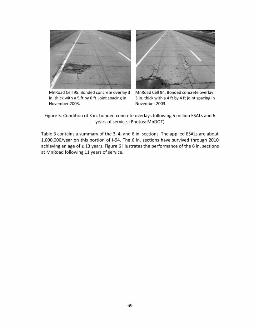
69
MnRoad Cell 95. Bonded concrete overlay 3 in. thick with a 5 ft by 6 ft joint spacing in November 2003.
MnRoad Cell 94. Bonded concrete overlay 3 in. thick with a 4 ft by 4 ft joint spacing in November 2003.
Figure 5. Condition of 3 in. bonded concrete overlays following 5 million ESALs and 6
years of service. (Photos: MnDOT) Table 3 contains a summary of the 3, 4, and 6 in. sections. The applied ESALs are about 1,000,000/year on this portion of I-94. The 6 in. sections have survived through 2010 achieving an age of ≥ 13 years. Figure 6 illustrates the performance of the 6 in. sections at MnRoad following 11 years of service.
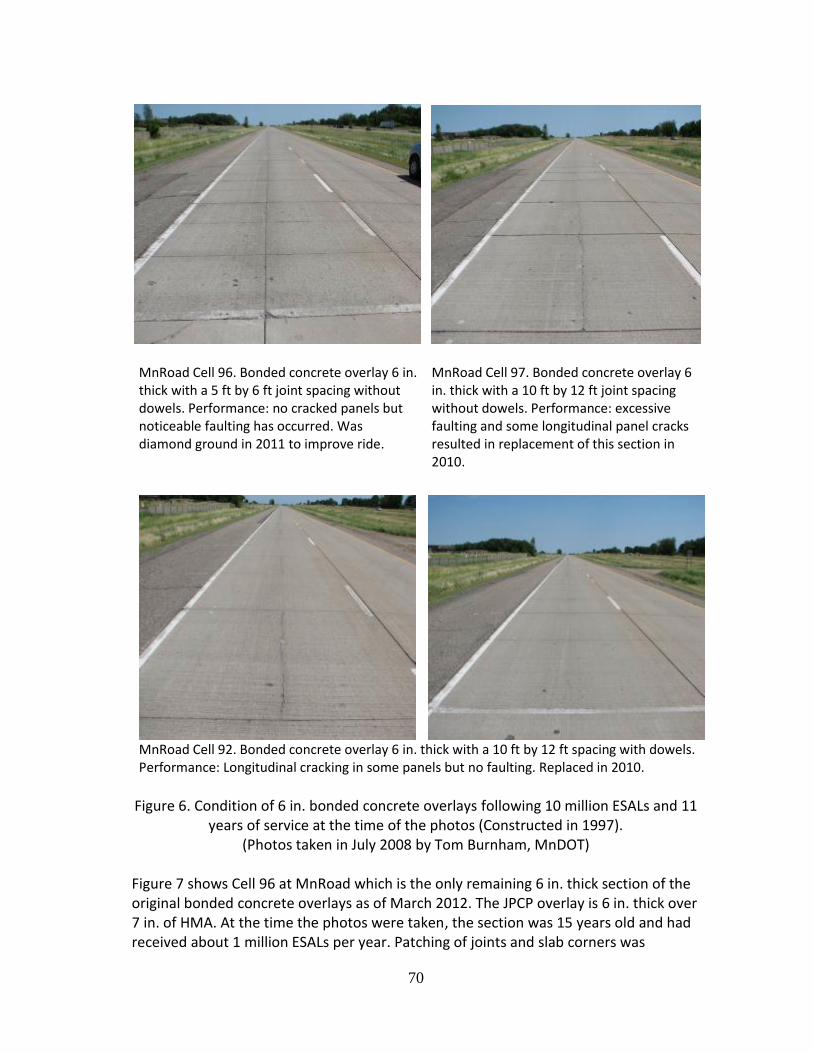
70
MnRoad Cell 96. Bonded concrete overlay 6 in. thick with a 5 ft by 6 ft joint spacing without dowels. Performance: no cracked panels but noticeable faulting has occurred. Was diamond ground in 2011 to improve ride.
MnRoad Cell 97. Bonded concrete overlay 6 in. thick with a 10 ft by 12 ft joint spacing without dowels. Performance: excessive faulting and some longitudinal panel cracks resulted in replacement of this section in 2010.
MnRoad Cell 92. Bonded concrete overlay 6 in. thick with a 10 ft by 12 ft spacing with dowels. Performance: Longitudinal cracking in some panels but no faulting. Replaced in 2010.
Figure 6. Condition of 6 in. bonded concrete overlays following 10 million ESALs and 11
years of service at the time of the photos (Constructed in 1997). (Photos taken in July 2008 by Tom Burnham, MnDOT)
Figure 7 shows Cell 96 at MnRoad which is the only remaining 6 in. thick section of the original bonded concrete overlays as of March 2012. The JPCP overlay is 6 in. thick over 7 in. of HMA. At the time the photos were taken, the section was 15 years old and had received about 1 million ESALs per year. Patching of joints and slab corners was

71
observed and grinding had been done in 2011. MnRoad representatives noted that transverse joint faulting was the primary distress which triggered the grinding.
Figure 7. Condition of the remaining 6 in. bonded concrete overlay--Cell 96 at MnRoad
in March 2012 (Photos by J. Mahoney)
Table 3. Initially constructed MnRoad bonded concrete overlay sections. (after Burnham, 2008)
Cell Type PCC Thickness (in.)
HMA Thickness (in.)
Panel Size (ft.)
Year Start-End
92 TWT 6 7 10 x 12 (doweled)
1997-2010
93 UTW 4 9 4 x 4 1997-2004
94 UTW 3 10 4 x 4 1997-2004
95 UTW 3 10 5 x 6 1997-2004
96 TWT 6 7 5 x 6 1997-present
97 TWT 6 7 10 x 12 1997-2010 Note: “Present” for Cell 96 is as of March 2012
Recap on Concrete Overlays There are two types of bonded concrete overlays for which state and LTPP performance data is available.
Bonded JPCP concrete overlays over HMA
Bonded concrete overlays over existing PCC Given the information summarized, the performance of bonded JPCP concrete overlays over existing HMA is a function of slab thickness and design details such as joints and
remaining HMA thickness. Given Interstate types of traffic ( 1 million ESALs per year), Table 4 shows an initial summary of typical pavement lives that can be expected for various slab thicknesses along with joint details. The expected lives shown are tentative and reflect a reasonable extrapolation the field data reviewed.
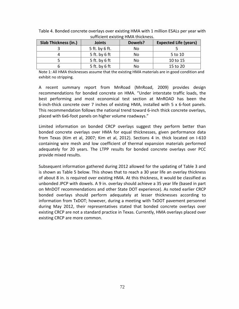
72
Table 4. Bonded concrete overlays over existing HMA with 1 million ESALs per year with sufficient existing HMA thickness.
Slab Thickness (in.) Joints Dowels? Expected Life (years)
3 5 ft. by 6 ft. No 5
4 5 ft. by 6 ft No 5 to 10
5 5 ft. by 6 ft No 10 to 15
6 5 ft. by 6 ft No 15 to 20 Note 1: All HMA thicknesses assume that the existing HMA materials are in good condition and exhibit no stripping.
A recent summary report from MnRoad (MnRoad, 2009) provides design recommendations for bonded concrete on HMA. “Under interstate traffic loads, the best performing and most economical test section at MnROAD has been the 6‐inch‐thick concrete over 7 inches of existing HMA, installed with 5 x 6‐foot panels. This recommendation follows the national trend toward 6‐inch thick concrete overlays, placed with 6x6‐foot panels on higher volume roadways.”
Limited information on bonded CRCP overlays suggest they perform better than bonded concrete overlays over HMA for equal thicknesses, given performance data from Texas (Kim et al, 2007; Kim et al, 2012). Sections 4 in. thick located on I-610 containing wire mesh and low coefficient of thermal expansion materials performed adequately for 20 years. The LTPP results for bonded concrete overlays over PCC provide mixed results. Subsequent information gathered during 2012 allowed for the updating of Table 3 and is shown as Table 5 below. This shows that to reach a 30 year life an overlay thickness of about 8 in. is required over existing HMA. At this thickness, it would be classified as unbonded JPCP with dowels. A 9 in. overlay should achieve a 35 year life (based in part on MnDOT recommendations and other State DOT experience). As noted earlier CRCP bonded overlays should perform adequately at lesser thicknesses according to information from TxDOT; however, during a meeting with TxDOT pavement personnel during May 2012, their representatives stated that bonded concrete overlays over existing CRCP are not a standard practice in Texas. Currently, HMA overlays placed over existing CRCP are more common.

73
Table 5. Bonded and unbonded JPCP concrete overlays over existing HMA with 1 million ESALs per year with sufficient existing HMA thickness (an update of Table 3
following meeting with MnDOT during March 2012)
Slab Thickness (in.) Bonded or
Unbonded
Joints Dowels? Expected Life (years)
3 Bonded 5 ft by 6 ft No 5
4 Bonded 5 ft by 6 ft No 5 to 10
5 Bonded 5 ft by 6 ft No 10 to 15
6 Bonded 6 ft by 6 ft No 15 to 20
7 Bonded 6 ft by 6 ft Optional 20 to 25
8 Unbonded 12 ft by 12 ft Yes 25 to 30
9 Unbonded 15 ft by 12 ft Yes 30 to 35
The preceding findings are supported by Harrington (2008) who states:
Bonded Overlays: Use to “…add structural capacity and/or eliminate surface distress when the existing pavement is in good structure condition. Bonding is essential, so thorough surface preparation is necessary before resurfacing.”
Unbonded Overlays: Use “…to rehabilitate pavements with some structural deterioration. They are basically new pavements constructed on an existing, stable platform (the existing pavement).”
Additional State Design and Construction Practices
A best practices document by Tayabji and Lim (2007) overviewed a selection of design, materials, and construction features for new concrete pavements for four State DOTs (Illinois, Minnesota, Texas, and Washington State). These practices were updated based on recent information and summarized in Tables 6 and 7. Minnesota and Washington State were grouped together in Table 5 since their practices are for JPCP. Illinois and Texas are summarized in Table 6 to reflect their CRCP practices. While these practices were developed with new pavement construction in mind, they are also applicable to long life concrete overlay systems. A recurring theme emerges when examining these practices: (1) thick unbonded PCC
slabs 11 in. are used, (2) design lives are all 30 years ranging up to 60 years, and (3) PCC mix and materials requirements are important. Thus, as expected, long life PCC renewal options are not just about slab thickness, but also materials and construction.
Thickness Summary Based largely on field sections in several states, unbonded JPCP overlays ≥ 8 in. placed on existing HMA or concrete are expected to last about 30 years. Most experience from

74
State DOTs suggests this type of overlay requires dowels at the transverse joints. Based on TxDOT experience, CRCP overlays over existing CRCP can achieve a 20 year life for a range of thicknesses (those reviewed ranged from a minimum of 2 in. up to 6.5 in.). TxDOT has accumulated substantial experience on both design and construction practices for this type of overlay.

75
Table 6. Examples of long-life JPCP standards for the Minnesota and Washington State. DOTs (Tayabji and Lim, 2007; MnDOT, 2005: WSDOT, 2010)
Item Minnesota DOT Washington DOT Design Life 60 years 50 years Typical Structure Slab thicknesses = 11.5 to 13.5”
3 to 8” dense-graded granular base
Subbase 12 to 48” select granular (frost-resistant)
Slab thickness = 12 to 13” (typical)
4” HMA base
4” crushed stone subbase
Joint Design Spacing = 15’ with dowels
All transverse joints are doweled
Spacing = 15’ with dowels
Joints saw cut with single pass
Hot poured sealant
Dowel Bars Diameter = 1.5” (typical)
Length = 15” (typical)
Spacing = 12”
Bars must be corrosion-resistant
Diameter = 1.5”
Length = 18”
Spacing = 12”
Bars must be corrosion-resistant Epoxy coatings not acceptable
Outside Lane and Shoulder
14’ lane with tied PCC or HMA
12’ lane with tied and dowel PCC
Surface Texture Astroturf or broom drag
Longitudinal direction
Requires 1 mm average depth in sand patch test (ASTM E965)
Longitudinal texturing
Alkali-Silica Reactivity
Fine aggregate must meet ASTM C1260 (ASR Mortar-Bar Method)
Expansion ≤ 0.15% OK. If ≥ 0.30%, reject.
Mitigation required by use of GGBFS or fly ash when expansion is between 0.15 and 0.30%
Allow various combinations of Class F fly ash and GGBFS
Aggregate Gradation
Use a combined gradation Use a combined gradation
Concrete Permeability
Use GGBFS or fly ash to lower permeability of concrete
Apply ASTM C1202 for rapid chloride ion permeability test
Air Content 7.0% ± 1.5% 5.5%
Water/Cementitious Ratio
≤ 0.40 ≤ 0.44
Minimum cementitious content = 564 lb/CY of PCC mix
Curing No construction or other traffic for 7 days or flexural strength ≥ 350 psi
Traffic opening compressive strength ≥ 2,500 psi by cylinder tests or maturity method
Construction Quality
Monitor vibration during paving

76
Table 7. Examples of long-life CRCP standards for the Illinois and Texas DOTs. (Tayabji and Lim, 2007; TxDOT, 2011; TxDOT, 2009a; TxDOT, 2009b)
Item Illinois DOT Texas DOT Design Life 30 to 40 years 30 years Typical Structure Up to 14” CRCP slab
4 to 6” HMA base
12” aggregate subbase
Up to 13” CRCP slab with one layer of reinforcing steel
14 to 15” CRCP slab with two layers of reinforcing steel
Uses stabilized base either 6” CTB with 1” HMA bond breaker on top or 4” HMA
Recommends tied PCC shoulders
Tie Bars Use at centerline and lane-to-shoulder joints
Use 1” by 30” bars spaced at 24”
CRCP Reinforcement
Reinforcement ratio = 0.8%
Steel depth 4.5” for 14” slabs
All reinforcement in CRCP epoxy-coated
Increased amount of longitudinal steel
Design details for staggering splices
Aggregate Requirements
IDOT applies tests to assess aggregate freeze-thaw and ASR susceptibilities
PCC Mix Limits the Coefficient of Thermal Expansion of concrete to ≤ 6 microstrains per °F
Construction Requirements
Limits on concrete mix temperature = 50 to 90°F
Slipform pavers must be equipped with internal vibration and vibration monitoring
Curing compound must be applied within 10 minutes of concrete finishing and tining
Curing ≥ 7 days before opening to traffic
Revised construction joint details
References References contained in this Supplemental Documentation are listed in the primary document—Appendix E-3.