not environmentally friendly - home page -...
TRANSCRIPT

ADMIRAL HD SERIES
Hydraulic Boat Steering INSTALLATION INSTRUCTIONS
& OWNER'S MANUAL
MANUFAC TURED BY
HY-DRIVE ENGINEERING PTY LTD ABN 14 007 660 808
59 WINGFIELD ROAD, WINGFIELD, SOUTH AUSTRALIA 5013
Telephone: +61 8 8243 1633 / Fax: +61 8 8445 7938 www.hydrive.com.au
Email: [email protected]
WARNING
Care of the ENVIRONMENT is the responsibility of all individuals and not that of someone else. If
you love fishing, boating, or make your living from either, then please take good care of the sea and it's
environment. HYDRAULIC OIL is NOT ENVIRONMENTALLY FRIENDLY and care
should be exercised to prevent oil used during the bleeding process from running overboard, or into the
bilge where it will be pumped into the sea.
It only takes a little time and patience to protect the sea from further pollution. Please dispose of all waste oil, rags, plastic bags and other materials,
thoughtfully and in a responsible manner.
WE WISH YOU HAPPY BOATING!
REVISION 2005-1 (21/03/2005)
INDEX
POINTS TO WATCH PRIOR TO INSTA LLATION ............................................3-9 INSTALLING AUTOPILOT ’S .................................................................................9-10 MOUNTING PUMPS ON AN A NGLE....................................................................11 INSTALLATION ON STANDA RD RUDDERS....................................................13 INSTALLATION ON INCLINED RUDDERS.......................................................14 TYPICAL CYLINDER INSTA LLATIONS ............................................................15 INSTALLATION OF PEDESTAL YA CHT STEERING .....................................19 BLEEDING OF SINGLE STATION SYSTEM S ...................................................23 BLEEDING OF DUAL STATIONS..........................................................................26 BLEEDING OF DUAL CYLINDERS ......................................................................27 BLEEDING FLUID LINK FOR CATAMARAN’S ...............................................28 SERVICING INFORMATION...................................................................................30 MAINT ENANCE INFORMATION..........................................................................31 WARRANTY INFORMATION.................................................................................42 TROUBLE SHOOTING GUIDE ...............................................................................40 BASIC SPECIFICATIONS .........................................................................................41
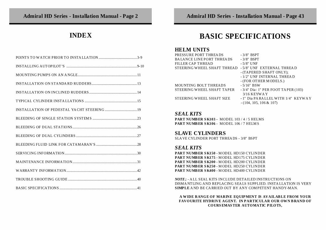
BASIC SPECIFICATIONS HELM UNITS PRESSURE PORT THREA DS - 3/ 8" BSPT BA LANCE LINE PORT THREA DS - 3/ 8" BSPT FILLER CAP THREAD - 5/ 8" UNF STEERING WHEEL SHAFT THREAD - 5/ 8" UNF EXTERNAL THREA D
- (TAPERED SHAFT ONLY); - 1/ 2" UNF INTERNAL THREA D - (FOR OT HER M ODELS.) MOUNTING BOLT THREADS - 5/ 16" BSW STEERING WHEEL SHAFT TAPER - 3/ 4" Dia : 1" PER FOOT TA PER (103)
3/16 KEYWA Y STEERING WHEEL SHAFT SIZE - 1" Dia PA RA LLEL WITH 1/ 4" KEYWA Y - (104, 105, 106 & 107) SEAL KITS PART NUMB ER S K103 - MODEL 103 / 4 / 5 HELMS PART NUMB ER S K106 - MODEL 106 / 7 HELM S SLAVE CYLINDERS SLA VE CYLINDER PORT THREA DS - 3/8" BSPT SEAL KITS PART NUMB ER S K150 - M ODEL HD150 CYLINDER PART NUMB ER S K175 - M ODEL HD175 CYLINDER PART NUMB ER S K200 - M ODEL HD200 CYLINDER PART NUMB ER S K250 - M ODEL HD250 CYLINDER PART NUMB ER S K400 - M ODEL HD400 CYLINDER NOTE ; - A LL SEAL KITS INCLUDE DETAILED INSTRUCTIONS ON DISMA NTLING AND REPLACING SEA LS SUPPLIED. INSTA LLATION IS VERY SIMPLE A ND BE CA RRIED OUT BY ANY COM PETENT HANDY-MAN.
A W IDE RANGE OF MARINE EQUIPMENT IS AVAILAB LE FROM YOUR FAVOURITE HYDRIVE AGENT. IN PARTICULAR OUR OW N B RAND OF
COURS EMAS TER AUTOMATIC P ILOTS,
Admiral HD Series - Installation Manual - Page 2 Admiral HD Series - Installation Manual - Page 43
Warranty Statement
HyDrive HD Series steering units are warranted by the manufacturer against defect in workmanship and materials for 24 months from date
of sale.
FACTORY WARRANTY
Units suspected of warranty problems should be returned to the factory, freight paid together with your name, address and
description of the problem. No inbound freight charges will be accepted.
Warranty is limited only to repair or replacement of any component
found to be faulty and such repair or replacement is solely at the discretion of the manufacturer. It does not extend to normal wear and
tear; collision damage; damage due to entry of foreign material; or corrosion due to electrolysis.
Should the repairs be affected by a DULY AUTHORISED
SERVIC EMAN, then warranty is limited only to the replacement of parts and the labour required to effectively install those parts. Travelling times are NOT covered by warranty but must be
compensated by the owner. HyDrive Engineering Pty Ltd will in no way be liable for more than the cost of the original product.
SAFETY INFORMATION
PLEASE READ THIS SECTION MOST CAREFULLY
It is absolutely ESSENTIAL that you read ALL the information contained in this MANUAL relating to your particular model and installation type BEFORE you attempt to install the unit. FAILURE to do so may result in problems when you come to bleed the unit later. ATTENTION HYDRAULIC EXPERTS - HYDRIVE hydraulic systems are NOT power-assisted units, and are extremely different from such systems, It is essential that EVEN YOU read this manual BEFORE atte mpting to install the system. We have a much higher incidence of installer-error with people who are supposedly hydraulic experts than your average handyman because they proceed on the mistaken assumption that HyDrive systems are just like all the others, or that they know all there is to know about installing our equipment. This statement is made in the interest of making it clear that our systems have specific requirements which may be unfamiliar to you. The time taken to read this booklet will ensure that the installation goes without a hitch.
THIS MANUAL HAS BEEN SUPPLIED FOR YOUR BENEFIT AND PROTECTION. IT IS OF NO VALUE IF YOU DO NOT READ IT
CAREFULLY PRIOR TO ATTEMPTING TO INSTALL YOUR NEW HYDRIVE UNIT. FAILURE TO ADHERE TO THESE INSTRUCTIONS
MAY RESULT IN STEERING FAILURE AND POTENTIAL DAMAGE TO THE BOAT AND INJURY TO THE OCCUPANTS. DO NOT TAKE
SHORT-CUTS. Stick strictly with our methods and do not adopt your own. It will make the system faster to install and safer to use.
Admiral HD Series - Installation Manual - Page 42 Admiral HD Series - Installation Manual - Page 3

VERY IMPORTANT POINTS TO NOTE Before proceeding please read the following sections relating to items that are of major importance to the correct installation and selection of components.
DO NOT USE BRAKE FLUID IN THIS SYSTEM - IT WILL DAMAGE SEALS AND OTHER COMPONENTS.
USE ONLY HYDRIVE ULTRA-15 HYDRAULIC OIL.
WARNING: Use of alternative hydraulic fluids may result in premature seal wear and possibly cause damage to your system. Such damage is not covered under your conditions of warranty. DO NOT USE ALTERNATIVE HYDRAULIC FLUID UN LESS THE
HELM IS USED ONLY AS AN EMERGENCY HELM SITUATION ON A POWER STEERING SYSTEM, WHICH USES
THE SAME FLUID. WHEN INSTALLING THE HD SERIES STEERIN G SYSTEMS YOU MAY ONLY USE COPPER TUBING FOR THE OIL LINES.
DO NOT SUBSTITUTE FOR AN Y OTHER TYPE OF TUBING OR
FLEXIBLE TUBING, NO MATTER WHAT YOUR TUBING SUPPLIER MAY ADVISE.
The performance of the steering can be seriously affected by the wrong tubing being installed, even if the burst pressure is greater than the metal tubing. BEFORE making any change to the tubing specs, contact your authorised HYRIVE dealer or the factory direct. Once again, nylon tubing OR Flexible Hydraulic Hose MUST
NOT be used on Heavy Duty Admiral Helms.
ALL WARRANTY IS VOID IF IN CORRECT TUBING IS USED.
It may affect one or if very dirty, can affect both directions of the pump. The simplest step to take is to try bleeding again with good clean oil. Often the object will be dislodged with rapid purge of clean oil. If this does not fix the problem, then the pump should be returned to a qualified service centre to be carried out by someone familiar with our equipment. Entry of foreign material is not covered by warranty. The same type of condition but to a lesser extent can be caused by a worn or damaged seal on the piston of the slave cylinder. If you find that the symptoms are identical in both directions, and that it is only slow, then chances are you require a new seal on the cylinder piston. This is not a difficult task and the instructions on the seal kit advise how to proceed with this. For details on any othe r problem contact your nearest dealer or fax or email to the factory with a detailed description of your problem.
Admiral HD Series - Installation Manual - Page 4 Admiral HD Series - Installation Manual - Page 41

Careful attention should be paid to the following sections on the correct installation of copper tubing to ensure safe and secure fitting of the tubing. COPPER tubing can be substituted with either STEEL or STAIN LESS STEEL hydraulic tubing. IT SHOULD NEVER BE SUBSTITUTED WITH HIGH PRESSUR E FLEXIBLE HYDRAULIC HOSE. THESE SYSTEMS SHOULD USE FULLY ANNEALED COPPER TUBING - 1/2" O.D. UN LESS THE LENGTH OF LINES WILL EXC EED 20 METRES (65FT) IN WHICH CASE, 5/8" COPPER TUBING SHOULD BE USED STEERING WHEEL DIAMETERS are of importance so please note the maximum recommended size listed below:
Model Shaft Size Minimum Wheel Diameter
103 ¾” Taper as standard -
Min: 18” (460mm) OPTIONAL 1” parallel
–must be specified
104 1” parallel as standard Min 30” (760mm)
105 1” parallel as standard Min 36” (900mm)
106 1” parallel as standard Min 40” (1000mm)
107 1” parallel as standard Min 48” (1200mm)
TROUBLE SHOOTING GUIDE
LUMPY OR NOTCHY STEERING The most common cause of this complaint is air in the system. C heck all joints and re-bleed the system. Another cause is the use of the wrong grade of tubing. High pressure flexible hoses can allow expansion, and result in notchy steering. It is dangerous - take it off the boat IMMEDIATELY, and get the right tubing. OIL OVERFLOWING Do not overfill the pump unit, but leave the oil level about 12mm from the bottom of the thread in the filler hole on the pump (about 1/2" from the bottom of the thread). If it still overflows on a hot day, then you have a pocket of air present in the system. Re-bleed the system. If problem persists on large installations - F it overflow tank (P/n EXPANSION ) TIGHT STEERING. Once again, the most common causes are air in the system, and the wrong grade of tubing used. Both faults allow compression of either the air or the tubing and the storage of pressure. This stored pressure results in heavy steering. Correct either of these faults. Another cause could be mechanical binding of rudder or motor pivot bearings. Disconnect steering from tiller and check again. If the steering is light and free, check for ease of movement of the tiller arm. If heavy / tight to move have it inspected for cause and fix. STEERING SLIPPING Should the pump appear to be slipping easily or turning without moving the cylinder, then the problem is probably related to some dirt or foreign body lodged in one of the pick up valves inside the pump.
Admiral HD Series - Installation Manual - Page 40 Admiral HD Series - Installation Manual - Page 5

RECOMMENDED TILLER LENGTHS vary from model to model and are adjustable depending on the rudder angle required.
POINTS TO WATCH PRIOR TO INSTALLATION
All hydraulic equipment requires a good degree of workmanship for its installation, and this is also true of steering gear, if future performance and serviceability is to be assured. Extra care must be taken by the installer to see the following points are closely watched. BE CLEAN when installing the unit. Strain all oil - even if it is new. It only takes a few moments to be particular. DO NOT CUT TUBING WITH A HACKSAW. Use a proper tube cutter for COPPER or steel tubing. Always make sure that no burrs or particles enter the tubing.
Recommended Tiller Lengths for 70 Degree Inclusive
Cylinder Type Inches Mm
HD150-9 8.015 203.581
HD175-10 8.906 226.212
HD150-12 10.687 271.450
(HD175-12 & HD200-12) 10.687 271.450
HD250-12 10.687 271.450
HD250-15 13.359 339.319
HD400-12 10.687 271.450
NOTES:
Admiral HD Series - Installation Manual - Page 6 Admiral HD Series - Installation Manual - Page 39

Dual Station Fluid Link
Lock
Va
lve
Hel
m
Pum
p H
elm
Pu
mp
Cylin
der
Cylin
der
Cat V
alve
Lock
V
alve
Hel
m
Pum
p
Cat V
alve
Cylin
ders
Hyd
raul
ic C
ircu
it
Sche
mat
ic L
ayou
t
Make sure that copper or steel tubing is saddled firmly at regular intervals of approximately 18” (450mm) to prevent vibration, noise and chaffing. WHEN USING COPPER IN AN ALUMINIUM BOAT there is no risk of galvanic action between the copper and aluminium providing that NYLON saddles are used to hold the copper in place. The saddles should be of the proper hydraulic type that holds the tubing clear of the hull or bulkhead. This means that there is NO metal-to- metal contact. ENSURE that all pipe joints and fittings are tight and carefully sealed using LOC-TITE THREAD SEALANT or similar product.
DO NOT use Teflon Tape as it can be introduced into the system by inexpe rienced installers and this is a regular cause of air leaks into the
system. THIS MAY CAUSE VALVE FAILURE. Use the RIGHT TOOLS for the job. DO NOT USE stilsen wrenches or pliers or incorrect spanners which will burr the fittings etc. Don't over-tighten bleeder valves etc. DO NOT RE-USE OIL FROM BLEEDING THE SYSTEM without first filtering it to remove foreign material (which will come out of the lines), and ALWAYS allow the air to settle out of it first. YO U WILL REQ UIRE FAR MORE OIL TO BLEED THE SYSTEM THAN YOU NEED TO FILL THE SYSTEM After installation, grease all points that have grease nipples (not bleeder nipples). Use good waterproof grease. This should be carried out every 6 months at which time you should always check the security of all bolts, nuts and split pins on the steering mechanism (Not every model has such items, so check your system thoroughly and become familiar with it). Vibration can often result in nuts becoming loose.
Admiral HD Series - Installation Manual - Page 38 Admiral HD Series - Installation Manual - Page 7

Single Station Fluid Link
Hel
m
Pum
p
Cat V
alve
Cylin
ders
Hel
m
Pum
p
Cylin
der
Cylin
der
Cat V
alve
Hyd
raul
ic C
ircu
it
Sche
mat
ic L
ayou
t
USING COPPER TUBING
Always use only FULLY ANNEALED tubing and the following rules should be strictly adhered to:- 1) Use compressed air and blow out all tubing to remove dust and debris from storage. DO NOT CUT WITH A HACKSAW - USE ONLY A PIPE CUTTER. 2) Avoid brazing or solde ring joints as this introduces scale and burnt flux into the tubes. Use commercial hydraulic jo ining fittings to avoid this. If you cannot or will not avoid soldering, then you MUST air-test each of the joints and flush the system using kerosene or similar to remove the solder, flux and scale BEFORE CONNECTING any part of it to the steering unit. 3) Where the tubing is to be bent, you should use a proper tube-bender to avoid kinking the tubing, which could result in firm steering. 4) F irst install the fittings into the cylinder and helm unit exactly as described in the instructions packed with the fittings themselves. S lide the nut onto the tube and, using a commercial or proper flaring tool, flare the end of the copper tubing. 5) P lace the flare in position against the fitting seat and slide up the nut and screw it on squarely so as not to cross the thread. Tighten it by hand only until it becomes firm. 6) YOU MUST USE TWO SPANNERS - one on the fitting (T-piece, elbow or straight fitting) and the other on the nut. Use the two spanners against each other to take the load - not the fitting. Use only 8" or 200mm long spanners - NO LARGER. In this way you can apply much greater force without damaging the fitting itself.
Admiral HD Series - Installation Manual - Page 8 Admiral HD Series - Installation Manual - Page 37
Dual Station with Auto Pilot
Autopilot Pum
p
Helm Pumps
Lock Valve
Ball Valves
Lock Valve
Cylinder
Lock Valve
Helm Pump
Helm Pump
Cylinder
Ba ll Va lves
Auto Pilot
Lock Valve
Hydraulic Circuit
Schematic Layout
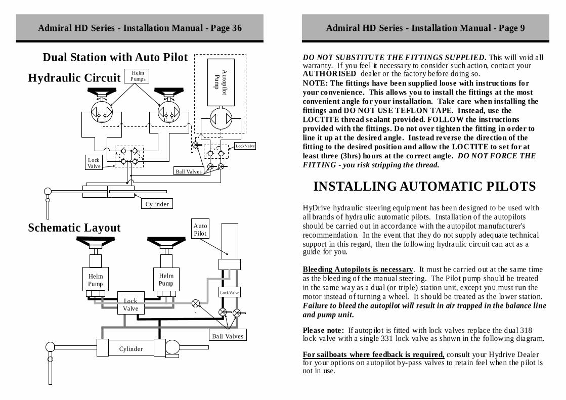
DO NOT SUBSTITUTE THE FITTINGS SUPPLIED. This will void all warranty. If you feel it necessary to consider such action, contact your AUTHORISED dealer or the factory before doing so. NOTE: The fittings have been supplied loose with instructions for your convenience. This allows you to install the fittings at the most convenient angle for your installation. Take care when installing the fittings and DO NOT USE TEFLON TAPE. Instead, use the LOCTITE thread sealant provided. FOLLOW the instructions provided with the fittings. Do not over tighten the fitting in order to line it up at the desired angle. Instead reverse the direction of the fitting to the desired position and allow the LOCTITE to set for at least three (3hrs) hours at the correct angle. DO NOT FORCE THE FITTING - you risk stripping the thread.
INSTALLING AUTOMATIC PILOTS HyDrive hydraulic steering equipment has been designed to be used with all brands of hydraulic automatic pilots. Installation of the autopilots should be carried out in accordance with the autopilot manufacturer's recommendation. In the event that they do not supply adequate technical support in this regard, then the following hydraulic circuit can act as a guide for you. Bleeding Autopilots is necessary. It must be carried out at the same time as the bleeding of the manual steering. The Pilot pump should be treated in the same way as a dual (or triple) station unit, except you must run the motor instead of turning a wheel. It should be treated as the lower station. Failure to bleed the autopilot will result in air trapped in the balance line and pump unit. Please note: If autopilot is fitted with lock valves replace the dual 318 lock valve with a single 331 lock valve as shown in the following diagram. For sailboats where feedback is required, consult your Hydrive Dealer for your options on autopilot by-pass valves to retain feel when the pilot is not in use.
Admiral HD Series - Installation Manual - Page 36 Admiral HD Series - Installation Manual - Page 9

Dual Station
Lock Valve
Helm Pump
Helm Pump
Cylinder
Lock Valve
Helm Pumps
Cylinder
Hydraulic Circuit
Schematic Layout
Admiral HD Series - Installation Manual - Page 10 Admiral HD Series - Installation Manual - Page 35
You will see that we recommend the use of a LOCK-VALVE in the circuit. The suppliers of your autopilot may suggest that this is unnecessary, however unless your autopilot pump is already fitted with one, we feel that our circuit is the ONLY way to absolutely guarantee steering in the event of failure of either the autopilot pump or solenoid valve (depending on the type). In order to determine if you require this lock-valve please consult with the supplier of the autopilot pump unit to see if it is equipped WITH IT'S OWN LOCK-VALVE or not. Keep in mind that if you decide not to fit the lock-valve for economy reasons only, then in the event of failure of the autopilot pump or solenoid valve it is POSSIBLE that the manual hydraulic steering may become TOTALLY INOPERABLE ALSO. For further information contact your nearest AUTHORISED dealer or contact the factory direct.
To Slave cylinder(s) T -
Balance line with vented filler cap. Manual helm
Lock valve
Autopilot Pump unit.
Either bi- directional OR Solonoid type unit.
STANDA RD AUTOPILOT INSTA LLATION DIA GRAM
(Do not use if one installed in p ilot pump already)
Optional 331 lock valve if autopilot has internally
fitted lock valve.
STANDARD AUTOPILOT INSTALLATION DIAGRAM
Ball valves should be installed as shown to isolate the autopilot circuit in case of failure and
to allow service of autopilot pump without losing steering control.
318 Dual Lock Valve used when pilot does not have own lock valve
Ball Valves

Lock Valve
Helm Pump
Cylinder
Ba ll Va lves
Auto Pilot
Lock Valve
Helm Pump
Cylinder
Autopilot Pum
p
Single Station with Auto Pilot
Hydraulic Circuit
Schematic Layout
INSTALLING PUMPS ON AN ANGLE Where HyDrive pumps are required to be installed at an angle other than horizontal, it may require some additional attention You will also need to obtain a remote filler kit (P/n CIP KIT). With all models, a special air-vent plug has been provided in the front of the pump body to allow the expulsion of air from inside the pump unit. The following instructions should be followed. 1. Drill an extra hole ( 3/4" diameter) in the dashboard, relative to the position of the front air- vent plug. This is a large round plug, sealed with an o-ring and has a large screw-driver slot in it.
BALANCE LINE TO LOWER STATION
BALANCE LINE TO UPPER STATION
PORTS TO CYLINDERS
Admiral HD Series - Installation Manual - Page 34 Admiral HD Series - Installation Manual - Page 11

Helm Pump
Cylinder
Helm Pump
Cylinder
Single Station
Hydraulic Circuit
Schematic Layout
2. Install the optional remote filler k it as shown in the filler kit’s installation instructions, and then install the helm pump with the studs supplied, ensuring that the hole lines up with the air-vent. 3. Fully install the rest of the system as per the relative installation instructions. 4. Once installed, proceed with the bleeding instructions by attaching the filler bottle to the remote filler kit. (Where dual stations are installed, if the inclined helm is the upper station, then bleed the lower unit as described in the dual instructions. Only follow this section when bleeding the upper station). Fill the filler bottle fully with oil. Next unscrew the air-vent filler cap 3-4 turns with a screw driver and "jiggle" the screw which should almost be out. This will allow the air to escape from behind. When oil starts to weep out past the threads, screw down the filler cap again. Keep the filler bottle full at all times. Should this process be too slow, then unscrew the filler cap further to allow the air to escape at a faster rate. 5) Bleed the system as described, however it is necessary to open up the air-vent at the end of bleeding each side to allow the air to escape that will accumulate in the helm unit. 6) AFTER bleeding the unit completely, undo the air- vent once more and ensure that no air is left trapped. In the case of a dual station with long lines, it may be necessary to fit an expansion tank (P/n EXPANSION) if some oil leakage is experienced through the remote filler kit on a very hot day. If the system is correctly bled this should prove unnecessary.
Admiral HD Series - Installation Manual - Page 12 Admiral HD Series - Installation Manual - Page 33

REGULARLY check
1) OIL LEVELS 2) SECURITY OF ALL BOLTS AND NUTS 3) SECURITY OF CLEVIS PINS, STUDS ETC. 4) SECURITY OF ALL HOSE FITTINGS 5) GREASE 6) SPRAY WITH RP7 OR SIMILAR PRODUCT 7) DO NOT MIX OILS IN THE UNIT.
ADDITIONAL INFORMATION
ON PAINTED COMPON ENTS, all aluminium castings are heavily protected by a special CHRO MATE CONVERSION process, but even so, where bare aluminium is scratched and exposed, it is in your interest to touch up all paint with a good quality marine paint to protect your investment. There is no need for any other type of maintenance on steering units, unless a problem becomes evident. If a problem does arise, always try to determine the cause as soon as possible. The trouble shooting guide will be of some help to you on that.
INSTALLING SLAVE CYLINDERS It is important for HD Series cylinders which are equipped with integral bleeder valves to be fitted with the bleeder valves on the top-side. This ensures that the air will be totally expelled during the bleeding operation. Air does not like travelling down-hill, so by fitting the nipples on top, simple bleeding is ensured. Note: There are alternative bleed positions on the top of each end cap to allow reversal of the bleeder valves. This allows the cylinder to be fitted on the opposite side. Be careful when changing, not to loose the small balls from each hole as these are the valve seals.
INSTALLATION ON STANDARD RUDDERS Hydrive standard cylinders with mounting brackets are designed for use with conventional rudders or jet units. The universal action of the mounting brackets assist in minor misalignments in the installation. The geometry of the installation is still very critical to the ultimate performance of the unit so the following sections should be studied carefully. RUDDER STOPS should always be fitted to limit the rudder movement, and should ensure the stops engage before the cylinder reaches the end of the stroke. This is to prevent cylinder damage in the event of underwater collision.
Admiral HD Series - Installation Manual - Page 32 Admiral HD Series - Installation Manual - Page 13

INSTALLATION ON INCLINED RUDDERS.
Although HyDrive cylinders are fitted with universal mounting brackets to compensate for minor misalignment and rudder movement, the amount of movement required on installations using inclined rudders is simply too great to be handled by the bracket, without inducing excessive wear.
In this case, a support bracket for the cylinder must be made so that the mounting bracket is fitted in the same plane as the tiller arm. You will see from the sketch (above), that a 'mounting wedge' is shown having a plane at 90 degrees to the rudder stock, so that the cylinder is then mounted in exactly the same relationship as one fitted to a normal vertical rudder. This simple wedge eliminates all unnecessary movement by the mounting bracket, and ensures that there is no side stress on the piston rod. The height of the wedge would need to be such that the cylinder clevis is at the right height to allow free movement for the entire stroke of the cylinder.
INCLINED RUDDER STOCK
TILLER ARM
WEDGE TO MATCH90deg
UNDER NO CIRCUMSTANCES attempt to dismantle a helm unit without obtaining service instructions for your dealer.
If under warranty, your warranty becomes void if dismantled by an un-authorised person. If poorly handled, you can damage your unit
beyond repair.
MAINTENANCE ON YOUR STEERING GEAR NOT TO BE FORGOTTEN!
Maintenance on HyDrive steering is minimal, but because of this is it is almost forgotten altogether. This results in problems at a later date due to wear on components that normally last a lifetime. Specifically mounting brackets do require to be greased at intervals of around 3 months during seasons of heavy use. If the boat is going to be left idle for long periods, the grease thoroughly the grease nipple on the slave cylinder and also cover the stainless shaft to prevent salt build-up etc which can cut the seals when first used. Any other exposed metal should be greased. ONLY USE WATERPROOF GREASE, as other automotive type greases can absorb moisture and may actually encourage corrosion.
Admiral HD Series - Installation Manual - Page 14 Admiral HD Series - Installation Manual - Page 31
5. Now that the system is totally bled, and NO air is present, then all that remains is for the cylinders to be positioned to align the rudders/motors. To do this, simply open the ball valve and rotate the helm unit one of the cylinders strokes out completely. The other cylinder is free to float, and can be moved by hand to line up in the same way. O nce lined up, simply close the ball valve and the cylinders will the track each other constantly.
6. To ensure that there is no air in the "tie-line", you should try pushing the
rudders or motors against each other. If you can compress them in-wards then there is air present, so re-bleed as outlined above.
THE SYSTEM IS READ Y FOR NORMAL OPERATION.
SERVICE INFORMATION
Servicing of HyDrive steering equipment is seldom required due to the design of the equipment, and in most cases is limited to seal replacements only. Full seal k its are available for each system and can be readily obtained from any of our dealers. Each seal kit comes with a simple instruction sheet on how to replace the seals in your unit. Before obtaining seals you must know the model number of your units, so check the labels before ordering the parts. SOME SIMPLE TERMS THAT WILL MAKE ORDERING PARTS MUCH SIMPLER - THE HELM UNITS WHERE THE WHEELS FIT ARE REFERRED TO AS PUMPS OR HELMS. THE SLAVE CYLINDERS ARE REFERRED TO AS CYLINDERS OR RAMS. TR Y NOT TO GET THE TWO CON FUSED, OR YOU MAY END UP WITH THE WRONG PARTS.
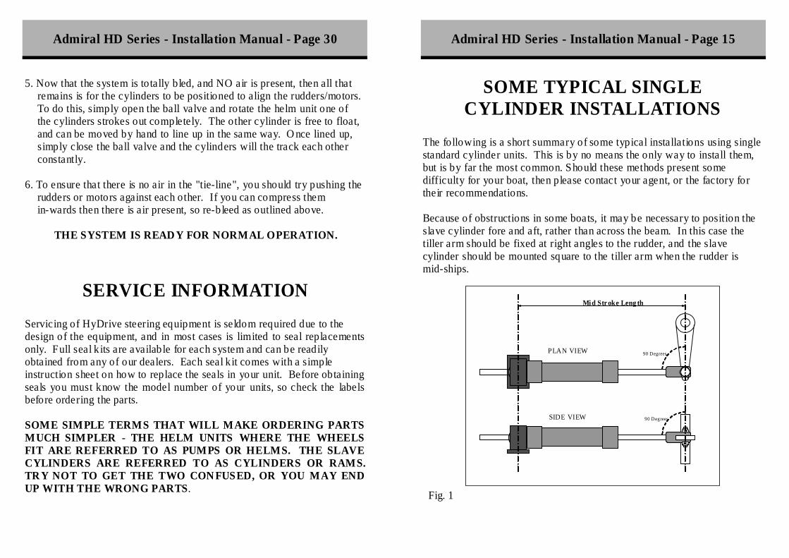
SOME TYPICAL SINGLE CYLINDER INSTALLATIONS
The following is a short summary of some typical installations using single standard cylinder units. This is by no means the only way to install them, but is by far the most common. Should these methods present some difficulty for your boat, then please contact your agent, or the factory for their recommendations. Because of obstructions in some boats, it may be necessary to position the slave cylinder fore and aft, rather than across the beam. In this case the tiller arm should be fixed at right angles to the rudder, and the slave cylinder should be mounted square to the tiller arm when the rudder is mid-ships.
Fig. 1
Mi d Str oke Leng th
90 Degrees
90 Degrees
PLAN VIEW
SIDE VIEW
Admiral HD Series - Installation Manual - Page 30 Admiral HD Series - Installation Manual - Page 15

FLUID LINK CIRCUIT FOR CATAMARAN
Helm Pump
Cylinder Cylinder
Cat Va lve
1 2 3 4
A typical single rudde r installation (as is shown in F ig.1 on previous page) The rudder should be in- line with the tiller arm, and the slave cylinder should be mounted squarely to the tiller arm at mid stroke. Please also note that the cylinder should be both square and parallel to the tiller arm. A typical double cylinder single rudder installation as shown below. Fig. 2. For twin rudde rs (as in F ig. 3.) the cylinder can be mounted on the outside of the tillers, or can push a pivot on the tie-rod itself. Please ensure that the cylinder is mounted so that it does not foul on the tie-bar as it turns hard-over.
Dual Cylinder - Single Rudder
Admiral HD Series - Installation Manual - Page 16 Admiral HD Series - Installation Manual - Page 29

cylinders themselves. With dual cylinders, the two bleeders diagonally opposite (if fitted to push-pull double tiller arm) are to be bled together, or at least one at a time whilst the helm is being rotated in the same direction. This ensures the total expulsion of air from each cylinder. This additional step is very simple, and should present no difficulties at all. All necessary information is given in the previous sections on bleeding both single and dual stations.
BLEEDING FLUID-LINK FOR CATAMARANS
1. Bleeding the fluid-link circuit is not difficult, and indeed the previous
sections on either dual or single station unit should be followed carefully. The only variations is to discover which direction the pump needs to rotate in order to bleed SIDE 4 as shown in the drawing below. This is the side that should be bled first - so simply follow the instructions as detailed in the single or dual station bleeding guide.
2. Bleed side 4 first, ensuring the ball valve is closed. 3. Close side 4, open the ball valve and then systematically bleed side 1, 2
and 3 whilst still rotating in the opposite direction. Open one bleeder valve at a time, and purge the oil through the helm as described in the previous sections. C lose the valves after bleeding for a period of a few minutes to purge the air.
4. Repeat steps 1 to 3 above once more. DON'T WORR Y IF THE
CYLINDERS APPEAR TO JAM WHEN YOU CLOSE THE BLEEDER VALVES, this is normal and because the cylinders are not yet synchronised.
INSTALLING CYLINDERS ON SAILBOATS
When installing HyDrive steering onto a sailboat, it is important to realise that the amount of feed-back you will receive from the unit is dependent on a number of factors. Firstly and most importantly, the correct unit must have been selected from the boat. If the unit is too large for the rudder, then feedback will be minimal. Also if the wheel turns are too high, or a very large wheel is used, then also the mechanical
Fig. 3.
Twin Rudder — Single Ram Twin Rudder - Single Ram
Admiral HD Series - Installation Manual - Page 28 Admiral HD Series - Installation Manual - Page 17

advantage ratio gives the wheel more power over the rudder than necessary for good sensitivity. A very simple means of allowing the feed-back to be tuned to suit the vessel is to vary the tiller length. The rudder must be fitted with rudder stops limiting the angle to 70 degrees. This gives a measure of adjustment on the "correct" sized unit, taking into account the wheel size used, the turns lock-to- lock and the amount of feel you want from the rudder. The following table gives a list of examples as a guide for you to use. Note that as the tiller length is reduced, the wheel load increases, the system pressure rises and the feed-back level increases. If you find that due to the fact that you have a small wheel, or a large rudder area which is heavy to handle, then you may need to increase the wheel turns to achieve comfortable steering.
Cylinder Model
Stroke inches
Tiller inches
Torque KgM
Volume cc's
Helm 103
Helm 104
Helm 105
Helm 106
Helm 107
150-9 9 8.0 107 172 4.9 4.0 2.0 1.4 1.0
150-9 x 2 9 8.0 215 344 10 8 4 3 2
150-12 12 10.7 143 229 6.5 5.3 2.7 1.8 1.4
150-12 x 2 12 10.7 286 458 13 11 5 4 3
175-10 10 8.9 185 296 8.4 6.9 3.4 2.4 1.8
175-10 x 2 10 8.9 369 591 17 14 7 5 4
175-12 12 10.7 221 355 10.1 8.2 4.1 2.8 2.1
175-12 x 2 12 10.7 443 709 20 16 8 6 4
200-12 12 10.7 289 463 13.2 10.8 5.4 3.7 2.8
200-12 x 2 12 10.7 578 927 26 22 11 7 6
200-15 15 13.4 362 579 16.5 13.5 6.7 4.6 3.5
200-15 x 2 15 13.4 723 1158 33 27 13 9 7
250-12 12 10.7 506 811 23.2 18.9 9.4 6.5 4.9
250-12 x 2 12 10.7 1012 1622 46 38 19 13 10
250-15 15 13.4 633 1014 29.0 23.6 11.8 8.1 6.1
250-15 x 2 15 13.4 1265 2027 58 47 24 16 12
400-12 12 10.7 1326 2124 60.7 49.4 24.7 17.0 12.9
400-12 x 2 12 10.7 2651 4247 121 99 49 34 26
WHEEL TURNS LOCK TO LOCK
Dual Cylinder - Single Rudder
7. Before changing directions, loosen off the SOLID filler cap on the lower station and allow accumulated air to escape. Replace the cap as soon as oil flows out.
8. Now repeat the bleeding in the opposite direction (as per step 6), at the
end of which you release the solid filler cap and allow any more air to escape that may have vented into the pump unit.
9. Follow steps 8 to 10 for final testing of the installation.
THE SYSTEM IS NOW READ Y FOR NORMAL USE. REMEMBER DON'T OVER FILL THE HELM UNIT,
PAR TICULARLY WITH DUAL STATIONS AS THE OIL VOLUME IS GREATER.
BLEEDING DUAL CYLINDERS Bleeding of dual cylinder systems should be carried out exactly in accordance with the relevant section on either SINGLE or DUAL STATIONS, with the only exception being the method of bleeding the
2
1
1
2
Admiral HD Series - Installation Manual - Page 18 Admiral HD Series - Installation Manual - Page 27

BLEEDING DUAL STATIONS 1. For bleeding of dual stations, the basic procedure is exactly as outlined
above, but with the addition of another station. F irstly it is necessary to use the SOLID filler cap provided in the DUAL HELM KIT in the upper station. It should be fitted firmly ensuring the O-ring seals on the pump body. Where the two stations are fitted on same level, simply choose one to be the vented station, and fit the solid filler cap to that one.
2. Having installed the solid filler cap in the upper station now follow
STEPS 1 TO 7 as detailed in the preceding section on bleeding SINGLE STATIONS to bleed the lower station.
3. Having bled the lower station (Steps 1 to 7), you are now ready to bleed
the upper station. REMOVE the solid filler cap from the upper station BEFORE removing the filler can. The oil level in the bottle will rise.
4. REMOVE the filler bottle and fit the SOLID filler cap to the lower
station, making sure the pump is totally full of oil. 5. Fill the upper station completely BEFORE fitting the filler cap and the
filler can etc. as before. Then fill the bottle and proceed to bleed the top station exactly as per steps 1 to 7 again.
6. Having bled the top station fully, it is now necessary to bleed air out of
the balance- line between the two stations. To do this, LEAVE the filler bottle attached to the top station, keep one person at that position maintaining the oil level, and then proceed to the lower station and bleed it once more going in the clockwise direction rapidly (as per step 3 to 5). C lose the bleeder nipple
INSTALLING HELM UNIT UNDER A PEDESTAL
Where a HyDrive helm unit is required to be fitted under a yacht pedestal and driven by a chain, it is recommended that the pump be installed as shown below. This ensures that the side- load of the chain is taken by the plumber-block bearing and not by the pump shaft bearing. This would prematurely wear both the bearing and the seal. Failure to install in this way may result in heavy steering, and premature wear. The bracket should be made in such a way as to have adjustment for chain stretch. For best performance, the chain must be correctly matched to the sprockets used, and must be in good condition and have no "slack". A loose chain will result in lumpy steering. The chain must be correctly in line with each of the sprockets otherwise steering action will be "rough" and notchy also.
PEDESTAL UNIT
DECK
BRACKET
AUTOPILOTSHAFT
GUSSET
HELMPUMP
PLUMBER-BLOCKBEARING
GUSSET
CHAIN
Admiral HD Series - Installation Manual - Page 19 Admiral HD Series - Installation Manual - Page 26

7. Repeat steps 5 and 6 once more, this time bleeding until no air is present in the oil. Then close the bleeder valves.
8. If all the air is out of the system, then the final test is the amount of
free-play in the system. With single stations, without lock-valves there should be NO free-play between wheel motion and cylinder motion. Where a lock valve is installed, there will be a very slight dwell when changing directions only, after this then motion in the same direction should be instant. If this is not the case, then you have not eliminated all of the air.
9. If you experience difficulties in getting the air out, then you should
firstly re-check your procedure against OURS. Many think that they can take short-cuts, or ignore our instructions, only to find they make a simple job a difficult one. If you have NOT done it our way, then start at the beginning and do it again OUR way. If you have indeed followed the instructions carefully, then repeat the procedure again, using fresh oil - no bubbles, making sure that the bleeder can, hose clamps and filler cap is all totally sealed firmly. If you still have trouble, then you must check each of your fittings, because air is being drawn INTO the system as you are bleeding the oil O UT. It cannot be caused any other way.
10. Now that the unit is bled correctly, you need to reduce the oil level in
the helm unit. To do this simply open the first bleeder screw used, and rotate the pump clockwise SLOWLY until the oil level in the bottle drops completely. DO NOT OVERDO THIS. The oil level should be exactly 12mm or 1/2" from the bottom of the thread in the filler hole. This allows for thermal expansion of the oil. If the pump is left totally full, then oil will overflow on a hot day.
THE UNIT IS READ Y FOR NORMAL USE
Admiral HD Series - Installation Manual - Page 20 Admiral HD Series - Installation Manual - Page 25
GETTING STARTED
The most important things to keep in mind before starting to install the unit is to ensure that you:- • 1) Have the right tools for the job. • 2) Have enough clean oil (Only HYDRIVE ULTRA-15) • 3) Have studied the preceding sections of this book, and know exactly which sections apply to your installation. • 4) Take care to follow ALL Instructions and Warnings given. • 5) Make NO changes to specifications of tubing, oil or method of installation without contacting your dealer FIRST. • 6) Study the circuit layout for your installation as shown in the hydraulic circuit drawings supplied at the rear of this manual.
Cylinder Upper Helm Unit
Vented Filler Cap
Flexib le Hoses
NOTE FLEXIBLE HOSES ONLY USED IF FITTED WITH COPPER TUBING, AND ONLY THOSE SUPPLIED WITH THE CYLINDER.
Single Station - Circuit Layout

3. You also have a smaller bore plastic hose which is to be fitted to the bleeder nipples of the cylinder, to direct oil into an CLEAN empty container. This oil can be re-filtered and re-used at another time. Connect this hose to the side of the cylinder attached to the STARBOARD side fitting of the helm unit. This is the fitting that will pump oil when the wheel is rotated clock-wise.
4. Unscrew that bleeder nipple 3 full turns and attach the hose. DO NOT
REMOVE THE BLEEDER SCREW completely as there is a small 7/32" diameter S/Steel ball underneath. If you lose this ball, you will be unable to proceed further. NEVER OPEN MORE THAN ONE BLEEDER AT A TIME.
5. For models 103, 4, & 5 turn the steering wheel CLOCKWISE at a speed
of 1 TURN PER SECOND. For models 106 & 7 turn the steering wheel CLOCKWISE at a speed of 1 TURN PER 2 SECONDS. DO NOT BLEED SLOWLY, as this will simply make your job either impossible or much slower. At no time let the oil in the filler bottle run out, but keep the level constant. DO NOT STOP TURNING THE WHEEL to maintain the oil level, as this will result in poor bleeding, particularly on larger craft. This is where the extra people come in, one to turn the wheel, one to top up the oil, and one to control the bleeder valves on the cylinder. Continue bleeding this side for a few MINUTES, and until a reasonably steady flow of oil is coming from the cylinder. It is not necessary for ALL air to be out of the oil at this point. DO NOT STOP BLEEDING just because the cylinder rod moves to the end of the stroke. This is normal and should be totally ignored.
6. AFTER a few minutes, stop turning the wheel and lock off the bleeder
valve. Change hose to the other bleeder, open it 3 turns and then reverse the direction of the wheel. Maintain the same speed for about the same length of time as before (The larger the boat - the longer the time). At this point the oil may still have some small air bubbles present. Lock off the bleeder.
Admiral HD Series - Installation Manual - Page 24 Admiral HD Series - Installation Manual - Page 21
NOW YOU ARE READY TO PROCEED
1. Firstly UNPACK all the cartons and carefully lay each component out
on a clean floor or table. Check to see that all the components are there and familiarise yourself with all the items, and fittings you have been supplied with.
2. Install the helm unit(s) into place firstly using the drill template
provided, and the studs and nuts supplied for this purpose. Keep the filler cap and the plugs in the pump at all times until the tubing is ready for attachment. Never leave the pump with the filler cap open or fittings uncovered to avoid dirt, sawdust etc from entering the pump unit.
Carefully loctite the fittings into place as per the
instructions supplied with them.
Cylinder
Upper Helm Unit
Lower Helm Unit
Solid Filler Cap
Vented Filler Cap
318 Double Lock Valve
Flexible Hoses
NOTE FLEXIBLE HOSES ONLY USED IF FITTED WITH COPPER TUBING, AND ONLY THOSE SUPPLIED WITH THE CYLINDER.
Balance Line
Dual Station - Circuit Layout
3. Install the cylinder(s) as shown in the previous sections, taking care to keep the geometry correct. Loctite fittings as per instructions.
4. Install any lock-valves or ball valves (if required) in a position that is
convenient to work in, and to reach with all the tubing. Keep in mind that the ball valve kit for catamaran-type steering must be easy to reach for re-synchronising the cylinders from time to time.
5. Install all tubing exactly as outlined in the hydraulic circuit drawings
supplied at the rear of this manual. For dual stations, do not forget to install the balance line as shown. Remember DO NOT solder copper tubing and DO NOT use teflon tape. Also SADDLE all copper tubing.
6. Be very careful with the fittings and the hose connections to each of the
components. R EMEMBER A FITTING THAT IS POORLY INSTALLED CAN LEAK AIR EVEN THOUGH IT DOES NOT LEAK OIL - THIS WILL CAUSE YOU TROUBLE IN BLEEDING THE SYSTEM. Cracked copper flares, thread sealant poorly applied and fittings simply not tight enough can all result in this problem.
Leave all loctited fittings 3-4 hours to set.
7. NOW YOU ARE R EAD Y TO B LEED THE SYSTEM and this will
be made much easier if you can obtain the assistance of two other people. The additional help will reduce bleeding time to only a few minutes.
Admiral HD Series - Installation Manual - Page 22 Admiral HD Series - Installation Manual - Page 23
BLEEDING SINGLE STATIONS
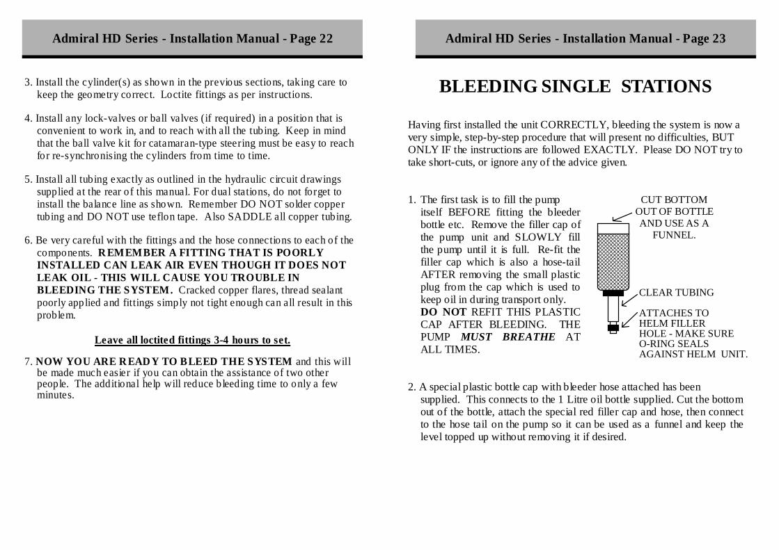
Having first installed the unit CORRECTLY, bleeding the system is now a very simple, step-by-step procedure that will present no difficulties, BUT ONLY IF the instructions are followed EXACTLY. Please DO NOT try to take short-cuts, or ignore any of the advice given. 1. The first task is to fill the pump
itself BEFORE fitting the bleeder bottle etc. Remove the filler cap of the pump unit and SLOWLY fill the pump until it is full. Re-fit the filler cap which is also a hose-tail AFTER removing the small plastic plug from the cap which is used to keep oil in during transport only. DO NOT REFIT THIS PLASTIC CAP AFTER BLEEDING. THE PUMP MUST BREATHE AT ALL TIMES.
2. A special plastic bottle cap with bleeder hose attached has been
supplied. This connects to the 1 Litre oil bottle supplied. Cut the bottom out of the bottle, attach the special red filler cap and hose, then connect to the hose tail on the pump so it can be used as a funnel and keep the level topped up without removing it if desired.
PIERCE HOLE
BOTTLE
CLEAR TUBING
ATTACHES TOHELM FILLERHOLE - MAKE SUREO-RING SEALSAGAINST HELM UNIT.
IN BASE OF
CUT BOTTOM OUT OF BOTTLE AND USE AS A
FUNNEL.


Cut a clearance hole to 60 m
m
Drill 4 holes @
3/8” D
iameter on a PC
D of
117.5mm
Instructions
This drill template is provided to assist you in m
arking and drilling the mounting
bolt holes for your new H
ydrive hydraulic steering pump.
Firstly tape the template in the correct position on the dashboard or the bulkhead.
If a hole already exists for the pump shaft, cut the central hole out of the tem
plate to allow
for accurate positioning of it. Then, using a 3/8” diameter drill bit, drill
through the four correct hole positions, making sure to keep the drill square to the
template. If no hole exists for the shaft, drill a 3/8” pilot hole through the centre
of the template to m
ark accurately the position to be bored.
Drill Tem
plate for 103, 104, 105, 106 &
107 Helm
s