non-destructive examination 2
TRANSCRIPT
8/4/2019 Non-Destructive Examination 2
http://slidepdf.com/reader/full/non-destructive-examination-2 1/148
IGCAR/QAD/QA&NDTS/NDEIGCAR/QAD/QA&NDTS/NDE 11
NONNON--DESTRUCTIVEDESTRUCTIVE
EXAMINATION / EXAMINATION /
EVALUATIONEVALUATION
R.SUBBARATNAMR.SUBBARATNAM
RETD., HEAD, QA&NDT SECTIONRETD., HEAD, QA&NDT SECTIONQUALITY ASSURANCE DIVISIONQUALITY ASSURANCE DIVISION
ENGINEERING SERVICES GROUPENGINEERING SERVICES GROUP
INDIRA GANDHI CENTRE FOR ATOMIC RESEARCHINDIRA GANDHI CENTRE FOR ATOMIC RESEARCH
KALPPAKAMKALPPAKAM
8/4/2019 Non-Destructive Examination 2
http://slidepdf.com/reader/full/non-destructive-examination-2 2/148
IGCAR/QAD/QA&NDTS/NDEIGCAR/QAD/QA&NDTS/NDE 22
--
EVALUATIONEVALUATION
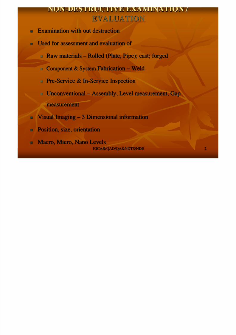
Examination with out destructionExamination with out destruction
Used for assessment and evaluation of Used for assessment and evaluation of
Raw materialsRaw materials –– Rolled (Plate, Pipe); cast; forgedRolled (Plate, Pipe); cast; forged
Component & SystemComponent & System FabricationFabrication –– WeldWeld
PrePre--Service & InService & In--Service InspectionService Inspection
UnconventionalUnconventional –– Assembly, Level measurement, GapAssembly, Level measurement, Gap
measurementmeasurement
Visual ImagingVisual Imaging –– 3 Dimensional information3 Dimensional information
Position, size, orientationPosition, size, orientation
Macro, Micro, Nano LevelsMacro, Micro, Nano Levels

8/4/2019 Non-Destructive Examination 2
http://slidepdf.com/reader/full/non-destructive-examination-2 3/148
IGCAR/QAD/QA&NDTS/NDEIGCAR/QAD/QA&NDTS/NDE 33
NDE METHODSNDE METHODS
LEAKTESTING
UE
RE EC
MPE
LPE
VISUAL
BASICNDE SURFACE
NDE
VOLUMETRIC
NDE
8/4/2019 Non-Destructive Examination 2
http://slidepdf.com/reader/full/non-destructive-examination-2 4/148
IGCAR/QAD/QA&NDTS/NDEIGCAR/QAD/QA&NDTS/NDE 44
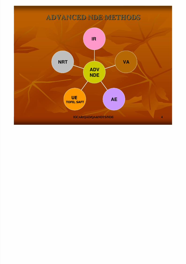
ADVANCED NDE METHODSADVANCED NDE METHODS
NRT
UETOFD, SAFT
AE
VA
IR
ADVNDE

8/4/2019 Non-Destructive Examination 2
http://slidepdf.com/reader/full/non-destructive-examination-2 5/148
IGCAR/QAD/QA&NDTS/NDEIGCAR/QAD/QA&NDTS/NDE 55
VISUAL EXAMINATIONVISUAL EXAMINATION
8/4/2019 Non-Destructive Examination 2
http://slidepdf.com/reader/full/non-destructive-examination-2 6/148
IGCAR/QAD/QA&NDTS/NDEIGCAR/QAD/QA&NDTS/NDE 66
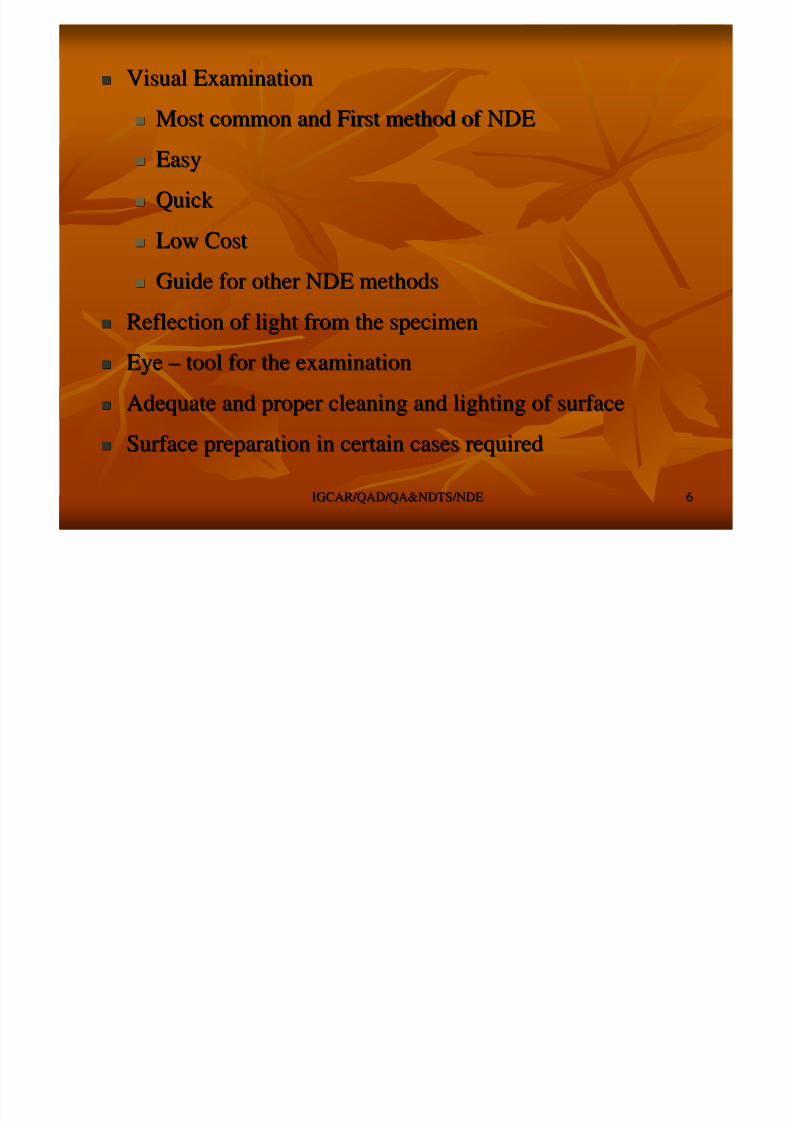
Visual ExaminationVisual Examination
Most common and First method of NDEMost common and First method of NDE
EasyEasy
Quick Quick
Low CostLow Cost
Guide for other NDE methodsGuide for other NDE methods
Reflection of light from the specimenReflection of light from the specimen
EyeEye –– tool for the examinationtool for the examination
Adequate and proper cleaning and lighting of surfaceAdequate and proper cleaning and lighting of surface
Surface preparation in certain cases requiredSurface preparation in certain cases required

8/4/2019 Non-Destructive Examination 2
http://slidepdf.com/reader/full/non-destructive-examination-2 7/148
IGCAR/QAD/QA&NDTS/NDEIGCAR/QAD/QA&NDTS/NDE 77
EYEEYE
The registering deviceThe registering device
VariableVariable –– individual point of viewindividual point of view
Variation in eyeVariation in eye
Unreliable with different light intensitiesUnreliable with different light intensities –– optical illusionoptical illusion
Relative brightness of different light sources can be judgedRelative brightness of different light sources can be judged
approximatelyapproximately –– with same order of brightnesswith same order of brightness
Large image if the retinal image is largeLarge image if the retinal image is large
Angle subtended at the eye by the object called theAngle subtended at the eye by the object called the ““VisualVisual
AngleAngle””

8/4/2019 Non-Destructive Examination 2
http://slidepdf.com/reader/full/non-destructive-examination-2 8/148
IGCAR/QAD/QA&NDTS/NDEIGCAR/QAD/QA&NDTS/NDE 88
VIEWINGVIEWING
Converging lens increases visual angle and increases the sizeConverging lens increases visual angle and increases the sizeof imageof image
Diameter of the pupil is ~2.5 mm for 5500 A wavelengthDiameter of the pupil is ~2.5 mm for 5500 A wavelength
Minimum angular separation of two points resolvable by theMinimum angular separation of two points resolvable by theeye is about one minute of arceye is about one minute of arc
Minimum size of the defect detected depends onMinimum size of the defect detected depends on
Surface being examinedSurface being examined
Brightness levelBrightness level Contrast between the area and the backgroundContrast between the area and the background
Brightness falling on the retina is most important than theBrightness falling on the retina is most important than thebrightness on the specimenbrightness on the specimen
Brightness on the retina is determined by area of pupilBrightness on the retina is determined by area of pupil Pupil size variable from 1 to 6 mm and hence the area variesPupil size variable from 1 to 6 mm and hence the area varies
by a factor of 36by a factor of 36
8/4/2019 Non-Destructive Examination 2
http://slidepdf.com/reader/full/non-destructive-examination-2 9/148
IGCAR/QAD/QA&NDTS/NDEIGCAR/QAD/QA&NDTS/NDE 99
SENSITIVITY OF EYESENSITIVITY OF EYE
Sensitivity of human eye varies for different wave lengthsSensitivity of human eye varies for different wave lengths
With ordinary conditions it is most sensitive to yellow green liWith ordinary conditions it is most sensitive to yellow green light withght with
wave length of 5500 Awave length of 5500 A
Human eye will provide satisfactory vision over wide range of coHuman eye will provide satisfactory vision over wide range of conditionsnditions
Eye has excellent visual perception, however adequate lighting iEye has excellent visual perception, however adequate lighting is primes prime
importanceimportance
Time of inspection permitted to work shall be limited to avoid eTime of inspection permitted to work shall be limited to avoid errors due torrors due to
decrease in visual reliability and discriminationdecrease in visual reliability and discrimination

8/4/2019 Non-Destructive Examination 2
http://slidepdf.com/reader/full/non-destructive-examination-2 10/148
IGCAR/QAD/QA&NDTS/NDEIGCAR/QAD/QA&NDTS/NDE 1010
LIGHTINGLIGHTING
The amount of light reaching shall be sufficient for bestThe amount of light reaching shall be sufficient for bestdefinition obtainable with aided or unaided eyedefinition obtainable with aided or unaided eye
Relation between the visual acuity and brightness shall beRelation between the visual acuity and brightness shall be
consideredconsidered The ratio of least perceptible brightness difference to theThe ratio of least perceptible brightness difference to the
brightness at which it is measured is nearly constant over largebrightness at which it is measured is nearly constant over largerange of 1 to 100000 candles / mrange of 1 to 100000 candles / m22 [ordinary interior[ordinary interior
illumination to bright day light]illumination to bright day light]
But the visual acuity varies quit sharply over the lower andBut the visual acuity varies quit sharply over the lower andmiddle portion of the rangemiddle portion of the range
visual acuity is considered to be dependant on the thresholdvisual acuity is considered to be dependant on the thresholdresponse of the cones in the retina. But no data available toresponse of the cones in the retina. But no data available togive explanation.give explanation.

8/4/2019 Non-Destructive Examination 2
http://slidepdf.com/reader/full/non-destructive-examination-2 11/148
IGCAR/QAD/QA&NDTS/NDEIGCAR/QAD/QA&NDTS/NDE 1111
OPTICAL AIDSOPTICAL AIDS
Optical aidsOptical aids
MirrorMirror
LensLens
MicroscopeMicroscope PeriscopePeriscope
TelescopeTelescope
FiberscopeFiberscope
BoroscopeBoroscope
Provide a means of compensating for the limits of visual acuityProvide a means of compensating for the limits of visual acuity
by enlarging small image in to largeby enlarging small image in to large
Improving viewing conditions for rapid inspection of smallImproving viewing conditions for rapid inspection of smallprecision parts, inaccessible areas and reducing operator fatiguprecision parts, inaccessible areas and reducing operator fatiguee
8/4/2019 Non-Destructive Examination 2
http://slidepdf.com/reader/full/non-destructive-examination-2 12/148
IGCAR/QAD/QA&NDTS/NDEIGCAR/QAD/QA&NDTS/NDE 1212
MIRRORMIRROR
Simplest way of looking inaccessible areaSimplest way of looking inaccessible area
Advantage of a portion of mirror is used and cone of Advantage of a portion of mirror is used and cone of rays is limited by the pupil of eyerays is limited by the pupil of eye
Other instrument / equipment can also be added withOther instrument / equipment can also be added withmirrormirror
Mirror surface shall be extremely flatMirror surface shall be extremely flat
Mirror must be kept free from dustMirror must be kept free from dust Reflecting power of mirror reduces after some periodReflecting power of mirror reduces after some period
of useof use
Reflecting power of two three mirrors are much lessReflecting power of two three mirrors are much less
However the reflecting power can be increased byHowever the reflecting power can be increased byspecial coatingspecial coating
8/4/2019 Non-Destructive Examination 2
http://slidepdf.com/reader/full/non-destructive-examination-2 13/148
IGCAR/QAD/QA&NDTS/NDEIGCAR/QAD/QA&NDTS/NDE 1313
BOROSCOPEBOROSCOPE
Boroscope is the instrument to inspect the inside surface of Boroscope is the instrument to inspect the inside surface of tube, bore or chambertube, bore or chamber
Precision built optical system with prism and lenses throughPrecision built optical system with prism and lenses through
which light also passeswhich light also passes Light source is located in font of object lens provides light inLight source is located in font of object lens provides light in
the required areathe required area
The design of the objective determines the angle of view, sizeThe design of the objective determines the angle of view, size
of visual field and amount of light gatheredof visual field and amount of light gathered
Design of the middle lenses has an important influence on theDesign of the middle lenses has an important influence on theimage obtained. Most middle lenses are achromatic for theimage obtained. Most middle lenses are achromatic for thepurpose of preserving the sharpness of the image and colorpurpose of preserving the sharpness of the image and colorvaluesvalues
Different angle of vision [0, 45, 60, 90]Different angle of vision [0, 45, 60, 90]

8/4/2019 Non-Destructive Examination 2
http://slidepdf.com/reader/full/non-destructive-examination-2 14/148
IGCAR/QAD/QA&NDTS/NDEIGCAR/QAD/QA&NDTS/NDE 1414
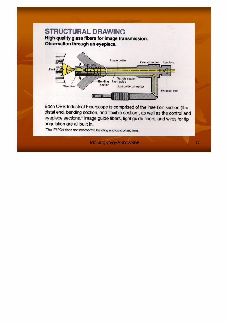
FIBERSCOPEFIBERSCOPE
Fiberscope is the instrument used to inspect surface of Fiberscope is the instrument used to inspect surface of pipeline. Compared to the Boroscope this is flexible and thepipeline. Compared to the Boroscope this is flexible and theimage transmission is by optical fibers.image transmission is by optical fibers.
Possibility of lighting of the surface of the objectPossibility of lighting of the surface of the object Various diameters, operating length and angle of viewing [0,Various diameters, operating length and angle of viewing [0,
45, 60, 90], backward and forward throw45, 60, 90], backward and forward throw
LimitationLimitation –– guiding to proper location is requiredguiding to proper location is required
Image acquisition in the digital form possible in bothImage acquisition in the digital form possible in both
Boroscope and FiberscopeBoroscope and Fiberscope

8/4/2019 Non-Destructive Examination 2
http://slidepdf.com/reader/full/non-destructive-examination-2 15/148
IGCAR/QAD/QA&NDTS/NDEIGCAR/QAD/QA&NDTS/NDE 1515

8/4/2019 Non-Destructive Examination 2
http://slidepdf.com/reader/full/non-destructive-examination-2 16/148
IGCAR/QAD/QA&NDTS/NDEIGCAR/QAD/QA&NDTS/NDE 1616
8/4/2019 Non-Destructive Examination 2
http://slidepdf.com/reader/full/non-destructive-examination-2 17/148
IGCAR/QAD/QA&NDTS/NDEIGCAR/QAD/QA&NDTS/NDE 1717
8/4/2019 Non-Destructive Examination 2
http://slidepdf.com/reader/full/non-destructive-examination-2 18/148
IGCAR/QAD/QA&NDTS/NDEIGCAR/QAD/QA&NDTS/NDE 1818
8/4/2019 Non-Destructive Examination 2
http://slidepdf.com/reader/full/non-destructive-examination-2 19/148
IGCAR/QAD/QA&NDTS/NDEIGCAR/QAD/QA&NDTS/NDE 1919
LIQUID PENETRANT EXAMINATIONLIQUID PENETRANT EXAMINATION
8/4/2019 Non-Destructive Examination 2
http://slidepdf.com/reader/full/non-destructive-examination-2 20/148
IGCAR/QAD/QA&NDTS/NDEIGCAR/QAD/QA&NDTS/NDE 2020
SURFACE NDESURFACE NDE
OPEN TO SURFACE DISCONTINUITIES ONLYOPEN TO SURFACE DISCONTINUITIES ONLY
PRINCIPLEPRINCIPLE –– CAPILARY ACTIONCAPILARY ACTION
SIX METHODSSIX METHODS
Two types & Three TechniquesTwo types & Three Techniques
FIVE STAGESFIVE STAGES
HIGH SENSITIVITY WITH POST EMULSIFICATION ANDHIGH SENSITIVITY WITH POST EMULSIFICATION AND
FLUREOSCENTFLUREOSCENT
1010 µ µ SENSITIVITY WITH FLOURESCENT AND 25SENSITIVITY WITH FLOURESCENT AND 25 µ µ WITH VISIBLEWITH VISIBLE -- SOLVENT REMOVALSOLVENT REMOVAL
Temp.Temp. –– 15 to 5015 to 50°° CC
8/4/2019 Non-Destructive Examination 2
http://slidepdf.com/reader/full/non-destructive-examination-2 21/148
IGCAR/QAD/QA&NDTS/NDEIGCAR/QAD/QA&NDTS/NDE 2121
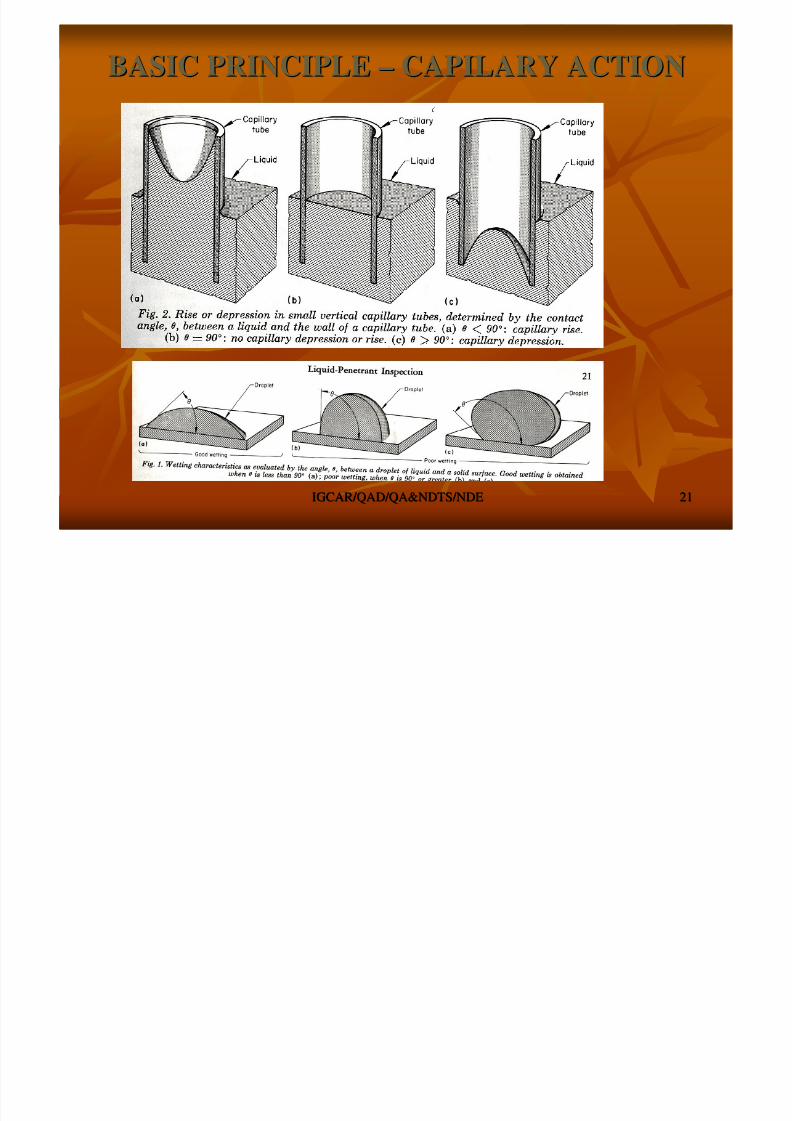
BASIC PRINCIPLEBASIC PRINCIPLE –– CAPILARY ACTIONCAPILARY ACTION
8/4/2019 Non-Destructive Examination 2
http://slidepdf.com/reader/full/non-destructive-examination-2 22/148
IGCAR/QAD/QA&NDTS/NDEIGCAR/QAD/QA&NDTS/NDE 2222
Factors influencing Penetrant infiltration intoFactors influencing Penetrant infiltration into
discontinuitiesdiscontinuities
surface tension of the liquid Penetrantsurface tension of the liquid Penetrant
discontinuity configuration constantdiscontinuity configuration constant surface coatings and contaminantssurface coatings and contaminants
additives and contaminants in the liquid Penetrantadditives and contaminants in the liquid Penetrant
mechanical obstructionsmechanical obstructions temperature of the test objecttemperature of the test object
roughness of the interior walls of the discontinuityroughness of the interior walls of the discontinuity

8/4/2019 Non-Destructive Examination 2
http://slidepdf.com/reader/full/non-destructive-examination-2 23/148
IGCAR/QAD/QA&NDTS/NDEIGCAR/QAD/QA&NDTS/NDE 2323
VISIBLEOR
FLOURSCENT
WATERWASHABLE
POSTEMULSIFICATION
SOLVENTREMOVABLE
LPE METHODSLPE METHODS

8/4/2019 Non-Destructive Examination 2
http://slidepdf.com/reader/full/non-destructive-examination-2 24/148
IGCAR/QAD/QA&NDTS/NDEIGCAR/QAD/QA&NDTS/NDE 2424
LPELPE -- STEPSSTEPS
PrePre--CleaningCleaning
PenetrantPenetrant ApplnAppln..
Dwell Time (10 min to >1 Hr.)Dwell Time (10 min to >1 Hr.) Penetrant CleaningPenetrant Cleaning
Water WashableWater Washable
Post EmulsificationPost Emulsification Solvent RemovableSolvent Removable
DeveloperDeveloper ApplnAppln. (Dry or Wet). (Dry or Wet)
Developing time (~5 min)Developing time (~5 min) InterpretationInterpretation
Post CleaningPost Cleaning

8/4/2019 Non-Destructive Examination 2
http://slidepdf.com/reader/full/non-destructive-examination-2 25/148
IGCAR/QAD/QA&NDTS/NDEIGCAR/QAD/QA&NDTS/NDE 2525
LPE STEPSLPE STEPS
8/4/2019 Non-Destructive Examination 2
http://slidepdf.com/reader/full/non-destructive-examination-2 26/148
IGCAR/QAD/QA&NDTS/NDEIGCAR/QAD/QA&NDTS/NDE 2626
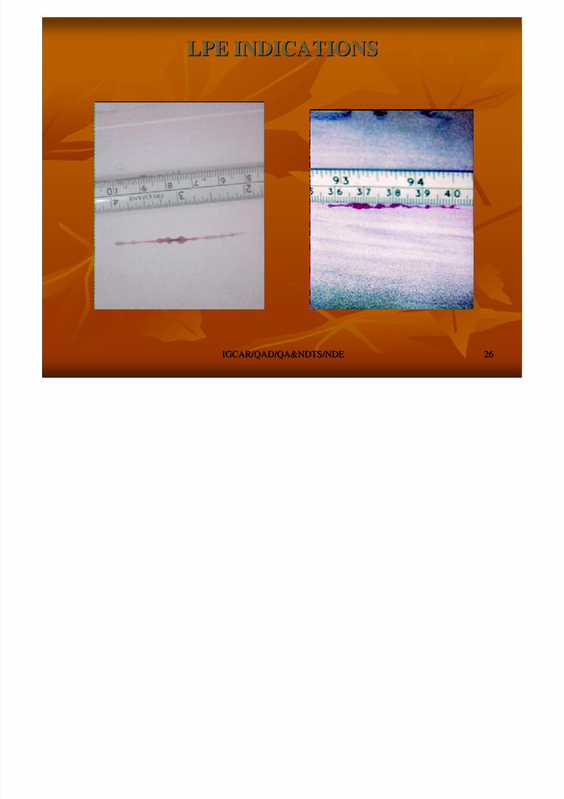
LPE INDICATIONSLPE INDICATIONS

8/4/2019 Non-Destructive Examination 2
http://slidepdf.com/reader/full/non-destructive-examination-2 27/148
IGCAR/QAD/QA&NDTS/NDEIGCAR/QAD/QA&NDTS/NDE 2727
LPE INDICATIONSLPE INDICATIONS

8/4/2019 Non-Destructive Examination 2
http://slidepdf.com/reader/full/non-destructive-examination-2 28/148
IGCAR/QAD/QA&NDTS/NDEIGCAR/QAD/QA&NDTS/NDE 2828
MAGNETIC PARTICLE EXAMINATIONMAGNETIC PARTICLE EXAMINATION
8/4/2019 Non-Destructive Examination 2
http://slidepdf.com/reader/full/non-destructive-examination-2 29/148
IGCAR/QAD/QA&NDTS/NDEIGCAR/QAD/QA&NDTS/NDE 2929
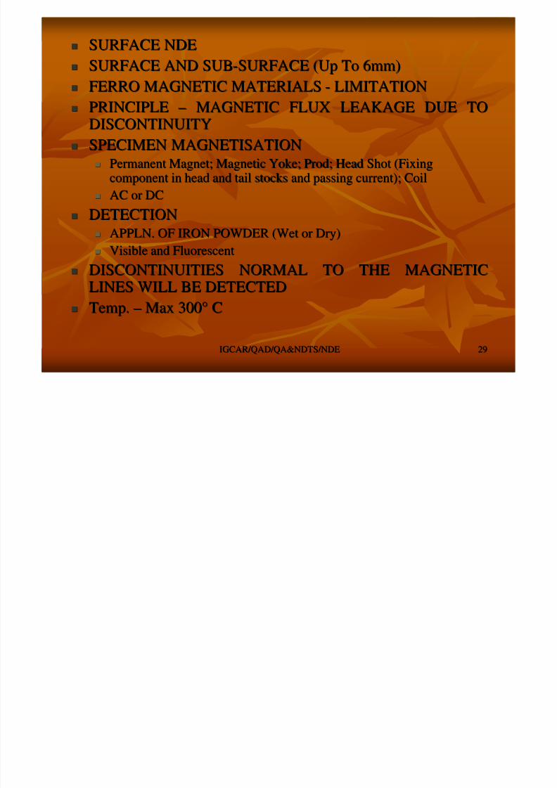
SURFACE NDESURFACE NDE
SURFACE AND SUBSURFACE AND SUB--SURFACE (Up To 6mm)SURFACE (Up To 6mm) FERRO MAGNETIC MATERIALSFERRO MAGNETIC MATERIALS -- LIMITATIONLIMITATION
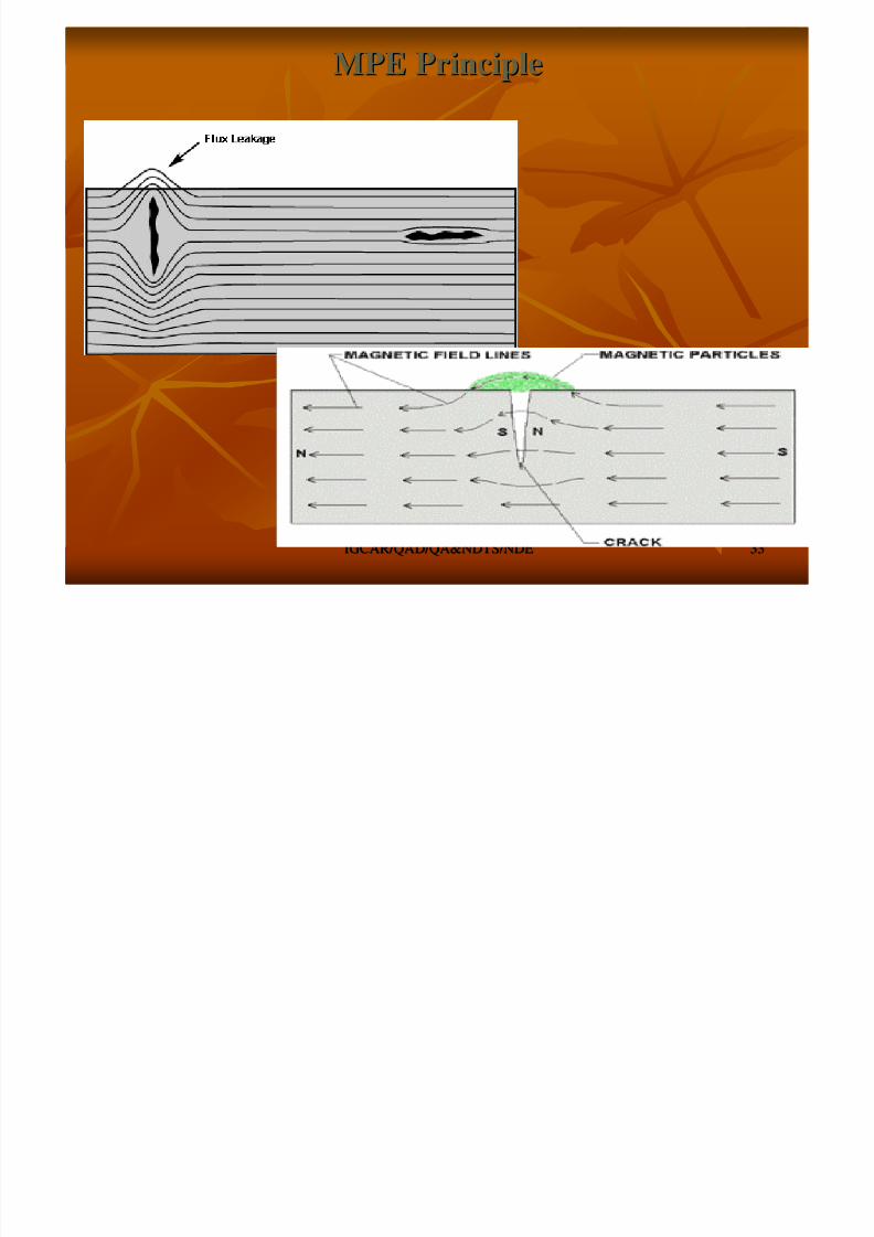
PRINCIPLEPRINCIPLE –– MAGNETIC FLUX LEAKAGE DUE TOMAGNETIC FLUX LEAKAGE DUE TODISCONTINUITYDISCONTINUITY
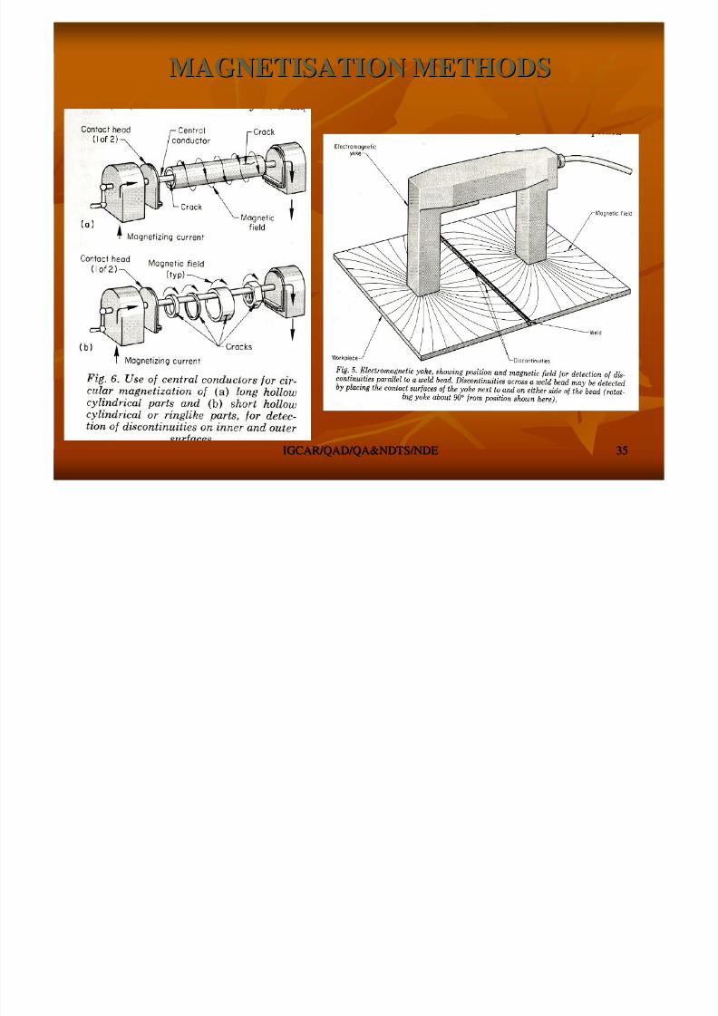
SPECIMEN MAGNETISATIONSPECIMEN MAGNETISATION Permanent Magnet; Magnetic Yoke; Prod; Head Shot (FixingPermanent Magnet; Magnetic Yoke; Prod; Head Shot (Fixing
component in head and tail stocks and passing current); Coilcomponent in head and tail stocks and passing current); Coil
AC or DCAC or DC
DETECTIONDETECTION APPLN. OF IRON POWDER (Wet or Dry)APPLN. OF IRON POWDER (Wet or Dry)
Visible and FluorescentVisible and Fluorescent
DISCONTINUITIES NORMAL TO THE MAGNETICDISCONTINUITIES NORMAL TO THE MAGNETICLINES WILL BE DETECTEDLINES WILL BE DETECTED
Temp.Temp. –– Max 300Max 300°° CC

8/4/2019 Non-Destructive Examination 2
http://slidepdf.com/reader/full/non-destructive-examination-2 30/148
IGCAR/QAD/QA&NDTS/NDEIGCAR/QAD/QA&NDTS/NDE 3030
Methods & Means of Methods & Means of
Generation of Magnetic FieldGeneration of Magnetic Field
Magnetisation with permanent Magnet and by Electric CurrentMagnetisation with permanent Magnet and by Electric Current(Induced)(Induced)
Characteristics of magnetic FieldCharacteristics of magnetic Field Field around permanent magnetField around permanent magnet
In & around a conductorIn & around a conductor
Types of MagnetisationTypes of Magnetisation
ContinuousContinuous ResidualResidual
CircularCircular
LongitudinalLongitudinal
Magnetic Fields in and around the jobMagnetic Fields in and around the job Longitudinal magnetizationLongitudinal magnetization
Circular MagnetisationCircular Magnetisation
Magnetic Field Strength & Field distributionMagnetic Field Strength & Field distribution
DemagnetizationDemagnetization
8/4/2019 Non-Destructive Examination 2
http://slidepdf.com/reader/full/non-destructive-examination-2 31/148
IGCAR/QAD/QA&NDTS/NDEIGCAR/QAD/QA&NDTS/NDE 3131
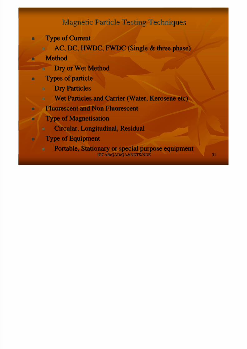
Magnetic Particle Testing TechniquesMagnetic Particle Testing Techniques
Type of CurrentType of Current
AC, DC, HWDC, FWDC (Single & three phase)AC, DC, HWDC, FWDC (Single & three phase)
MethodMethod
Dry or Wet MethodDry or Wet Method
Types of particleTypes of particle
Dry ParticlesDry Particles
Wet Particles and Carrier (Water, Kerosene etc)Wet Particles and Carrier (Water, Kerosene etc)
Fluorescent and Non FluorescentFluorescent and Non Fluorescent
Type of MagnetisationType of Magnetisation
Circular, Longitudinal, ResidualCircular, Longitudinal, Residual
Type of EquipmentType of Equipment
Portable, Stationary or special purpose equipmentPortable, Stationary or special purpose equipment

8/4/2019 Non-Destructive Examination 2
http://slidepdf.com/reader/full/non-destructive-examination-2 32/148
IGCAR/QAD/QA&NDTS/NDEIGCAR/QAD/QA&NDTS/NDE 3232
Magnetic Particle Test Equipments & AccessoriesMagnetic Particle Test Equipments & Accessories
EquipmentsEquipments PermanentPermanent
Electro MagnetElectro Magnet -- YokesYokes
Small , medium, Stationary and Portable EquipmentsSmall , medium, Stationary and Portable Equipments TypeType
Prods (Circular Mag.)Prods (Circular Mag.)
Coils (Longitudinal Mag.)Coils (Longitudinal Mag.) Head Shot (Circular Mag.)Head Shot (Circular Mag.)
Black Light (Fluorescent) EquipmentsBlack Light (Fluorescent) Equipments
PIE Gauge,PIE Gauge, KETOKETO’’ss Ring, Shims with Notches forRing, Shims with Notches forfield measurement & Gauge for residual mag. Fieldfield measurement & Gauge for residual mag. Fieldmeasurementmeasurement
8/4/2019 Non-Destructive Examination 2
http://slidepdf.com/reader/full/non-destructive-examination-2 33/148
IGCAR/QAD/QA&NDTS/NDEIGCAR/QAD/QA&NDTS/NDE 3333
MPE PrincipleMPE Principle

8/4/2019 Non-Destructive Examination 2
http://slidepdf.com/reader/full/non-destructive-examination-2 34/148
IGCAR/QAD/QA&NDTS/NDEIGCAR/QAD/QA&NDTS/NDE 3434
MAGNETISATION METHODSMAGNETISATION METHODS
8/4/2019 Non-Destructive Examination 2
http://slidepdf.com/reader/full/non-destructive-examination-2 35/148
IGCAR/QAD/QA&NDTS/NDEIGCAR/QAD/QA&NDTS/NDE 3535
MAGNETISATION METHODSMAGNETISATION METHODS
8/4/2019 Non-Destructive Examination 2
http://slidepdf.com/reader/full/non-destructive-examination-2 36/148
IGCAR/QAD/QA&NDTS/NDEIGCAR/QAD/QA&NDTS/NDE 3636
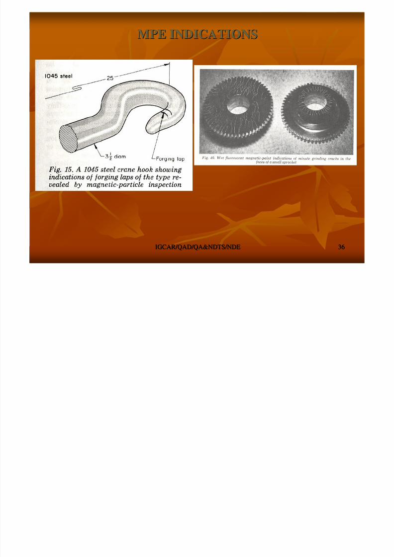
MPE INDICATIONSMPE INDICATIONS
M i P i l I di i
8/4/2019 Non-Destructive Examination 2
http://slidepdf.com/reader/full/non-destructive-examination-2 37/148
IGCAR/QAD/QA&NDTS/NDEIGCAR/QAD/QA&NDTS/NDE 3737
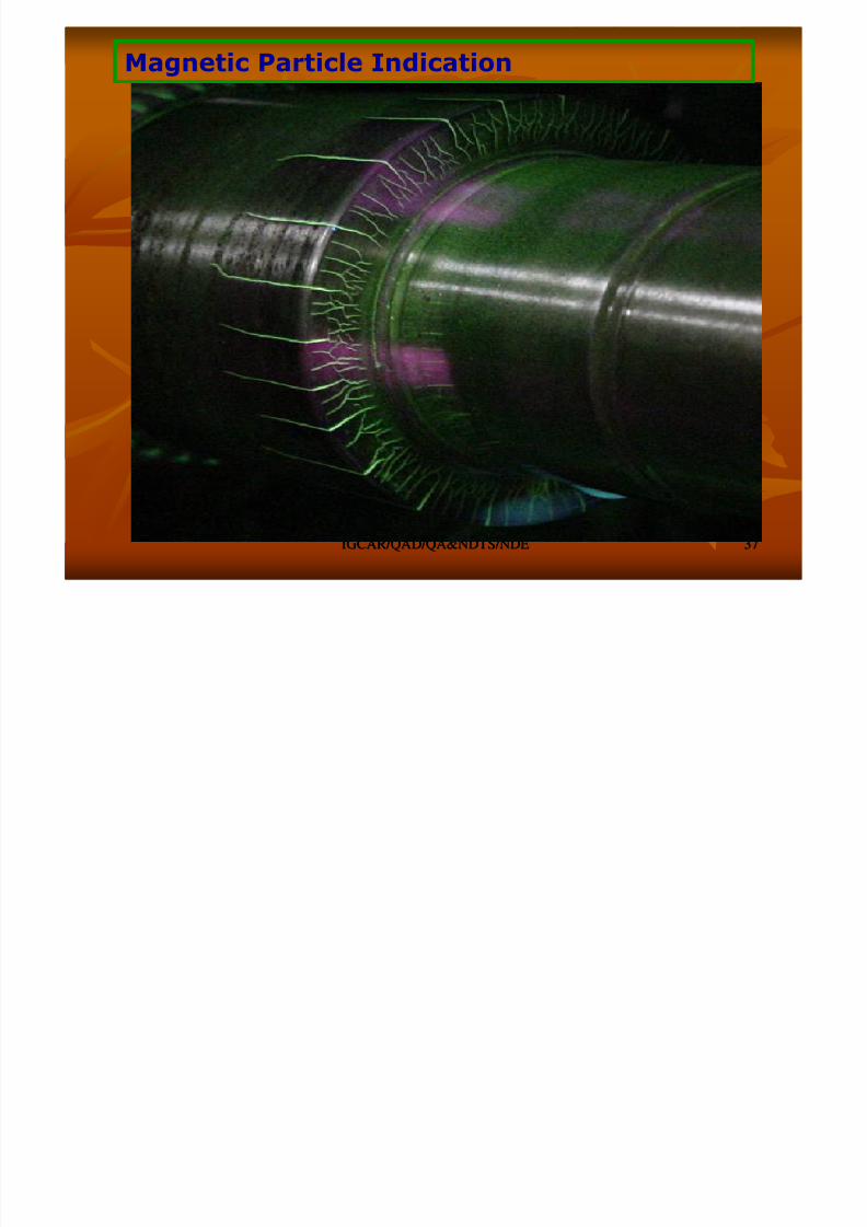
Magnetic Particle Indication

8/4/2019 Non-Destructive Examination 2
http://slidepdf.com/reader/full/non-destructive-examination-2 38/148
IGCAR/QAD/QA&NDTS/NDEIGCAR/QAD/QA&NDTS/NDE 3838
EDDY CURRENT EXAMINATIONEDDY CURRENT EXAMINATION

8/4/2019 Non-Destructive Examination 2
http://slidepdf.com/reader/full/non-destructive-examination-2 39/148
IGCAR/QAD/QA&NDTS/NDEIGCAR/QAD/QA&NDTS/NDE 3939
SURFACE NDESURFACE NDE
SURFACE AND SUBSURFACE AND SUB--SURFACE (Up To 6 mm)SURFACE (Up To 6 mm) CONDUCTIVE MATERIALCONDUCTIVE MATERIAL –– LIMITATIONLIMITATION
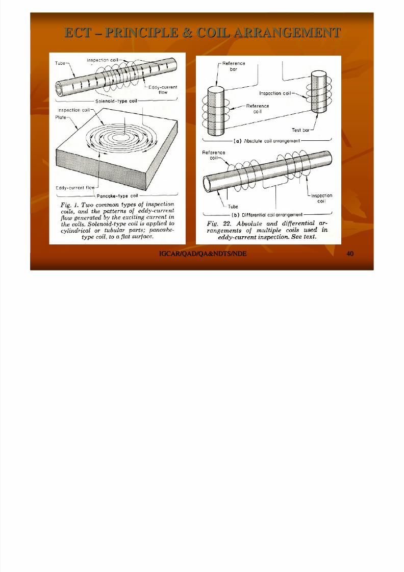
PRINCIPLEPRINCIPLE –– INDUCTION OF CURRENT (CIRCULARINDUCTION OF CURRENT (CIRCULAR ––EDDY) IN THE SPECIMEN AND ANALYSINGEDDY) IN THE SPECIMEN AND ANALYSINGINTERACTION (Induction, Permeability)INTERACTION (Induction, Permeability)
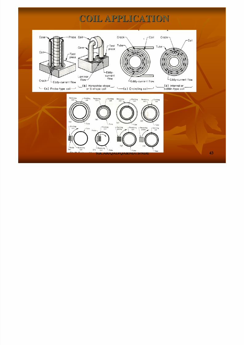
PROBE CONFIGURATIONPROBE CONFIGURATION
Encircling or Bobbin; Surface; Multiple Frequency ProbesEncircling or Bobbin; Surface; Multiple Frequency Probes
DISCONTINUITIES NORMAL TO EDDY CURRENTDISCONTINUITIES NORMAL TO EDDY CURRENTDETECTABLEDETECTABLE
EXAMINATION FAST (Less Time)EXAMINATION FAST (Less Time)
USED FORUSED FOR
Material Sorting (Permeability; Electrical Conductivity); DefectMaterial Sorting (Permeability; Electrical Conductivity); DefectDetection; Coating Thk.Detection; Coating Thk.
8/4/2019 Non-Destructive Examination 2
http://slidepdf.com/reader/full/non-destructive-examination-2 40/148
IGCAR/QAD/QA&NDTS/NDEIGCAR/QAD/QA&NDTS/NDE 4040
ECTECT –– PRINCIPLE & COIL ARRANGEMENTPRINCIPLE & COIL ARRANGEMENT
8/4/2019 Non-Destructive Examination 2
http://slidepdf.com/reader/full/non-destructive-examination-2 41/148
IGCAR/QAD/QA&NDTS/NDEIGCAR/QAD/QA&NDTS/NDE 4141
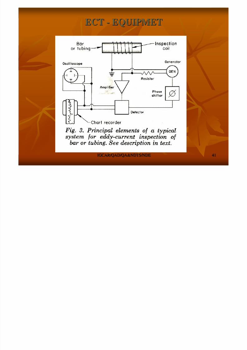
ECTECT -- EQUIPMETEQUIPMET
8/4/2019 Non-Destructive Examination 2
http://slidepdf.com/reader/full/non-destructive-examination-2 42/148
IGCAR/QAD/QA&NDTS/NDEIGCAR/QAD/QA&NDTS/NDE 4242
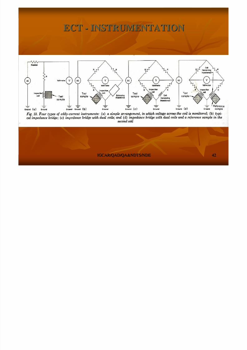
ECTECT -- INSTRUMENTATIONINSTRUMENTATION
COIL APPLICATIONCOIL APPLICATION
8/4/2019 Non-Destructive Examination 2
http://slidepdf.com/reader/full/non-destructive-examination-2 43/148
IGCAR/QAD/QA&NDTS/NDEIGCAR/QAD/QA&NDTS/NDE 4343
COIL APPLICATIONCOIL APPLICATION

8/4/2019 Non-Destructive Examination 2
http://slidepdf.com/reader/full/non-destructive-examination-2 44/148
IGCAR/QAD/QA&NDTS/NDEIGCAR/QAD/QA&NDTS/NDE 4444
Eddy Current InspectionEddy Current Inspection
Probe
Signals producedby variousamounts ofcorrosionthinning.
Periodically, power plants areshutdown for inspection.Inspectors feed eddy current
probes into heat exchangertubes to check for corrosiondamage.
Pipe with damage

8/4/2019 Non-Destructive Examination 2
http://slidepdf.com/reader/full/non-destructive-examination-2 45/148
IGCAR/QAD/QA&NDTS/NDEIGCAR/QAD/QA&NDTS/NDE 4545
RADIOGRAPHIC EXAMINATIONRADIOGRAPHIC EXAMINATION
PRINCIPLES OF RADIOGRAPHYPRINCIPLES OF RADIOGRAPHY

8/4/2019 Non-Destructive Examination 2
http://slidepdf.com/reader/full/non-destructive-examination-2 46/148
IGCAR/QAD/QA&NDTS/NDEIGCAR/QAD/QA&NDTS/NDE 4646
PRINCIPLES OF RADIOGRAPHYPRINCIPLES OF RADIOGRAPHY Differential absorption of short wavelength radiationsDifferential absorption of short wavelength radiations
Difference in density is the effect of Difference in density is the effect of
variations in thickness of the part,variations in thickness of the part,
differences in absorption characteristics caused by variations idifferences in absorption characteristics caused by variations inncompositions.compositions.
Shadow projection, an image, on a detectorShadow projection, an image, on a detector -- varying grey levelsvarying grey levels
SourcesSources -- XX--rays, gamma rays, neutrons, protons, electrons.rays, gamma rays, neutrons, protons, electrons.
X and gamma rays are common sources for industrial radiographyX and gamma rays are common sources for industrial radiography
DetectorDetector –– radiographic films, image intensifiers or scintillatorradiographic films, image intensifiers or scintillatorscreens / counters.screens / counters.
Double coated, fine grain, high contrast XDouble coated, fine grain, high contrast X--ray films usedray films used
Radiography is the best method for the detection of volumetricRadiography is the best method for the detection of volumetricdefects.defects.
It can be applied on a variety of component ranging from miniatuIt can be applied on a variety of component ranging from miniaturereintegrated circuits to mammoth missile parts and complexintegrated circuits to mammoth missile parts and complexassemblies.assemblies.

8/4/2019 Non-Destructive Examination 2
http://slidepdf.com/reader/full/non-destructive-examination-2 47/148
IGCAR/QAD/QA&NDTS/NDEIGCAR/QAD/QA&NDTS/NDE 4747
RADIOGRAPHY SET UPRADIOGRAPHY SET UP
Source
Specimen
Variation inRadiographicDensity

8/4/2019 Non-Destructive Examination 2
http://slidepdf.com/reader/full/non-destructive-examination-2 48/148
IGCAR/QAD/QA&NDTS/NDEIGCAR/QAD/QA&NDTS/NDE 4848
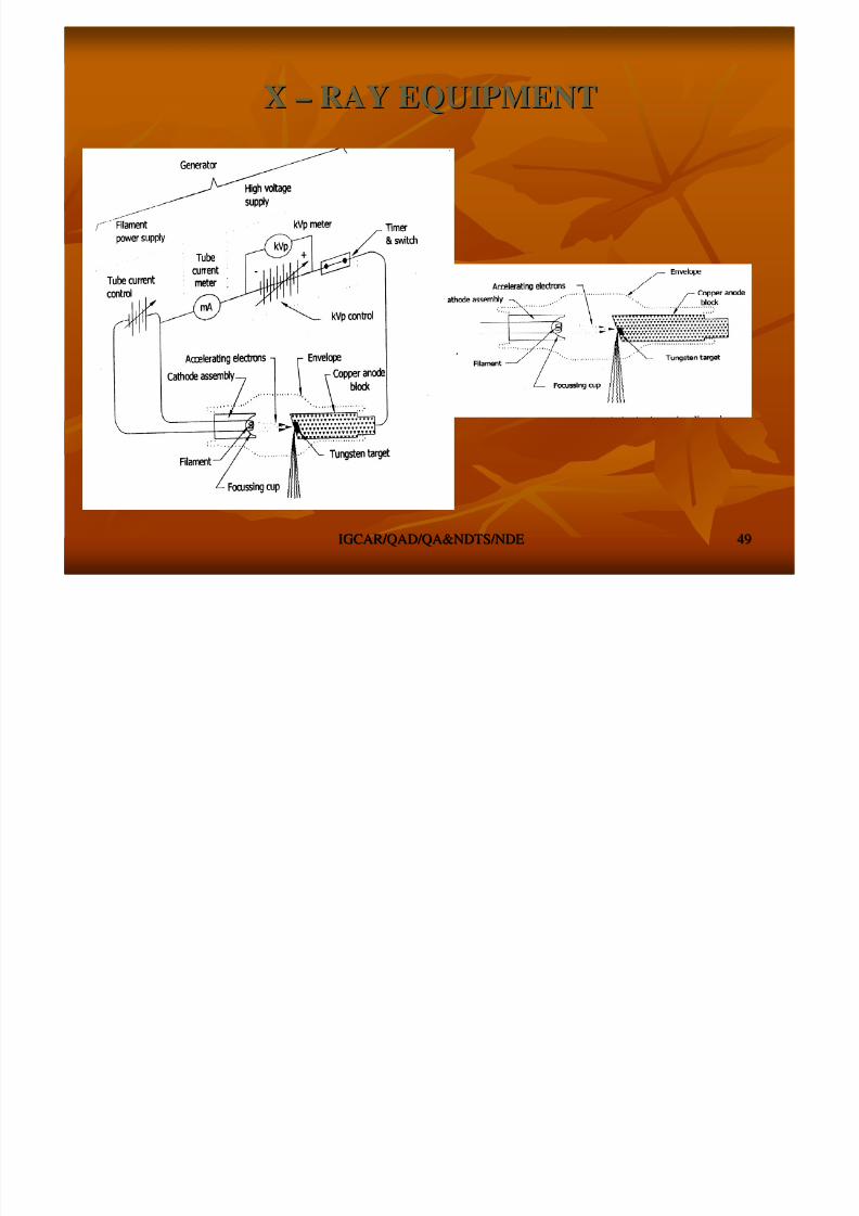
SOURCES OF RADIATIONSSOURCES OF RADIATIONS –– X RAYX RAY
XX--ray and gamma raysray and gamma rays
XX--ray machine consistsray machine consists
XX--ray tube head, highray tube head, high--voltage generators, control unit, cooling circuit.voltage generators, control unit, cooling circuit.
Glass tube headsGlass tube heads -- earlier, modern Xearlier, modern X--ray headsray heads -- metal ceramicmetal ceramic When fast moving electrons impinging on a metal target XWhen fast moving electrons impinging on a metal target X--rayray
is produced .is produced .
Most of the energy (98%)Most of the energy (98%) -- as heat, only a fraction isas heat, only a fraction is
converted into Xconverted into X--rays.rays.
Depends on the atomic number of the target material, level of Depends on the atomic number of the target material, level of vacuum.vacuum.
XX--ray tube targetray tube target -- high atomic number and high melting pointhigh atomic number and high melting point-- TungstenTungsten
8/4/2019 Non-Destructive Examination 2
http://slidepdf.com/reader/full/non-destructive-examination-2 49/148
IGCAR/QAD/QA&NDTS/NDEIGCAR/QAD/QA&NDTS/NDE 4949
XX –– RAY EQUIPMENTRAY EQUIPMENT
GAMMA RAY
8/4/2019 Non-Destructive Examination 2
http://slidepdf.com/reader/full/non-destructive-examination-2 50/148
IGCAR/QAD/QA&NDTS/NDEIGCAR/QAD/QA&NDTS/NDE 5050
GAMMA RAYGAMMA RAY
Isotopic sources emitting gamma raysIsotopic sources emitting gamma rays -- extensive applications.extensive applications.
Main advantage of gamma ray sourcesMain advantage of gamma ray sources
simplicity of apparatus, compactness and portability.simplicity of apparatus, compactness and portability.
does not require cooling and power supplydoes not require cooling and power supply -- field applications.field applications. Main disadvantage of these sourcesMain disadvantage of these sources
decay with time and hence required replacementdecay with time and hence required replacement
energy of the gamma rays is fixed and cannot be varied to matchenergy of the gamma rays is fixed and cannot be varied to match thethe
thickness of objects for better sensitivity.thickness of objects for better sensitivity. The commonly used gamma sources are CobaltThe commonly used gamma sources are Cobalt--60, Iridium60, Iridium--
192, Cesium 137 and Thulium 170.192, Cesium 137 and Thulium 170.

8/4/2019 Non-Destructive Examination 2
http://slidepdf.com/reader/full/non-destructive-examination-2 51/148
IGCAR/QAD/QA&NDTS/NDEIGCAR/QAD/QA&NDTS/NDE 5151
GAMMA RAY SOURCESGAMMA RAY SOURCES
0.250.250.380.380.550.551.31.3OUTPUTOUTPUT
RHM/CiRHM/Ci
127 Days127 Days33.1 Yrs33.1 Yrs74 Days74 Days5.3 Yrs5.3 YrsHALFHALF
LIFELIFE
0.052,0.052,
0.0840.084
0.660.660.45 (0.45 (AvgAvg))1.1.7 &1.1.7 &
1.331.33
ENERGYENERGY
(MeV)(MeV)
THULIUMTHULIUM
170170
CESIUMCESIUM
137137
IRIDIUMIRIDIUM
192192
COBALTCOBALT
6060
GAMMA CAMERA / EXPOSUREGAMMA CAMERA / EXPOSURE
8/4/2019 Non-Destructive Examination 2
http://slidepdf.com/reader/full/non-destructive-examination-2 52/148
IGCAR/QAD/QA&NDTS/NDEIGCAR/QAD/QA&NDTS/NDE 5252
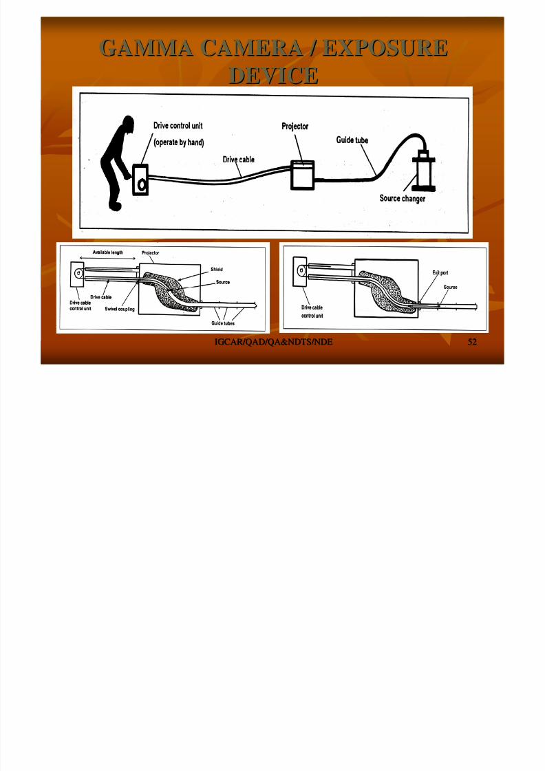
GAMMA CAMERA / EXPOSUREGAMMA CAMERA / EXPOSURE
DEVICEDEVICE
RADIOGRAPHIC FILMRADIOGRAPHIC FILM
8/4/2019 Non-Destructive Examination 2
http://slidepdf.com/reader/full/non-destructive-examination-2 53/148
IGCAR/QAD/QA&NDTS/NDEIGCAR/QAD/QA&NDTS/NDE 5353
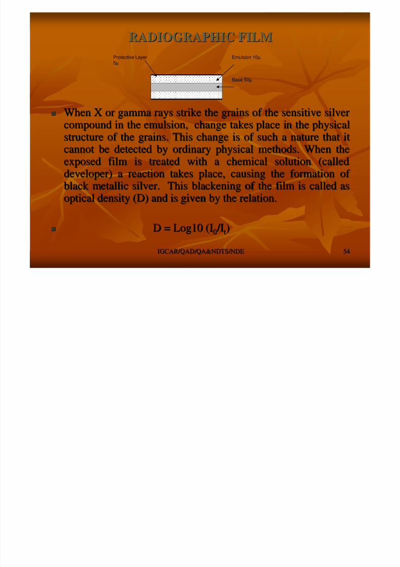
RADIOGRAPHIC FILMRADIOGRAPHIC FILM
Radiographic film most widely used as detectorsRadiographic film most widely used as detectors ConsistsConsists -- base, emulsion, binding layer protective layerbase, emulsion, binding layer protective layer
Polyester is mostPolyester is most--commonly used material for film basecommonly used material for film base
Emulsion of Emulsion of silver bromidesilver bromide
is coated over the baseis coated over the base Gelatin acts a binding layer between film base andGelatin acts a binding layer between film base and
emulsion.emulsion.
protective layerprotective layer -- hardened gelatin, serves to protect thehardened gelatin, serves to protect the
emulsion from physical damage, abrasion and stressemulsion from physical damage, abrasion and stressmarks.marks.
Industrial radiographic films are double coatedIndustrial radiographic films are double coated
the emulsion is coated on both sides of the base.the emulsion is coated on both sides of the base.
increases the film speed.increases the film speed.
RADIOGRAPHIC FILMRADIOGRAPHIC FILM
8/4/2019 Non-Destructive Examination 2
http://slidepdf.com/reader/full/non-destructive-examination-2 54/148
IGCAR/QAD/QA&NDTS/NDEIGCAR/QAD/QA&NDTS/NDE 5454
RADIOGRAPHIC FILMRADIOGRAPHIC FILM
When X or gamma rays strike the grains of the sensitive silverWhen X or gamma rays strike the grains of the sensitive silvercompound in the emulsion, change takes place in the physicalcompound in the emulsion, change takes place in the physicalstructure of the grains. This change is of such a nature that itstructure of the grains. This change is of such a nature that it
cannot be detected by ordinary physical methods. When thecannot be detected by ordinary physical methods. When theexposed film is treated with a chemical solution (calledexposed film is treated with a chemical solution (calleddeveloper) a reaction takes place, causing the formation of developer) a reaction takes place, causing the formation of black metallic silver. This blackening of the film is called asblack metallic silver. This blackening of the film is called as
optical density (D) and is given by the relation.optical density (D) and is given by the relation.
D = Log10 (ID = Log10 (I00 /I /Itt))
Base 50µ
Protective Layer5µ
Emulsion 10µ

8/4/2019 Non-Destructive Examination 2
http://slidepdf.com/reader/full/non-destructive-examination-2 55/148
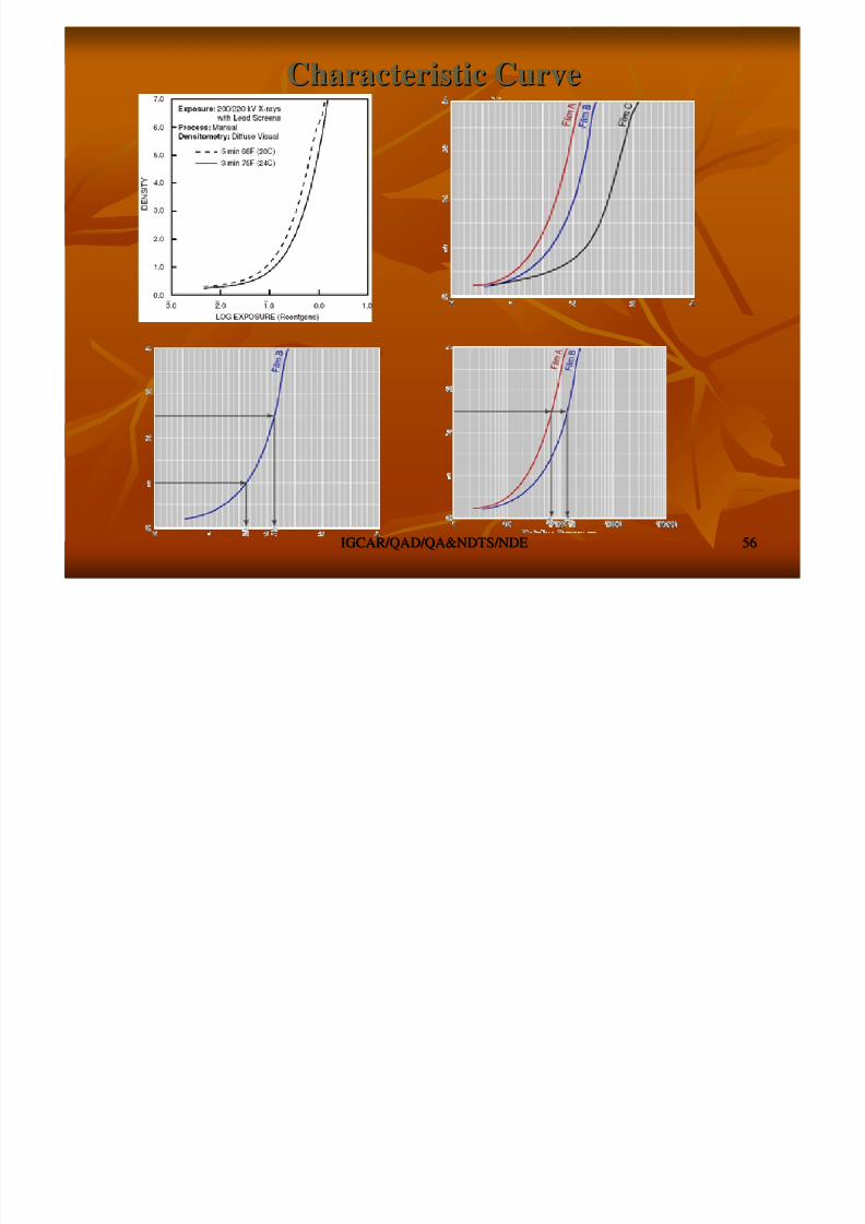
Characteristic CurveCharacteristic Curve
8/4/2019 Non-Destructive Examination 2
http://slidepdf.com/reader/full/non-destructive-examination-2 56/148
IGCAR/QAD/QA&NDTS/NDEIGCAR/QAD/QA&NDTS/NDE 5656
Characteristic CurveCharacteristic Curve
Intensifying ScreensIntensifying Screens
d d h i d i h i li
8/4/2019 Non-Destructive Examination 2
http://slidepdf.com/reader/full/non-destructive-examination-2 57/148
IGCAR/QAD/QA&NDTS/NDEIGCAR/QAD/QA&NDTS/NDE 5757
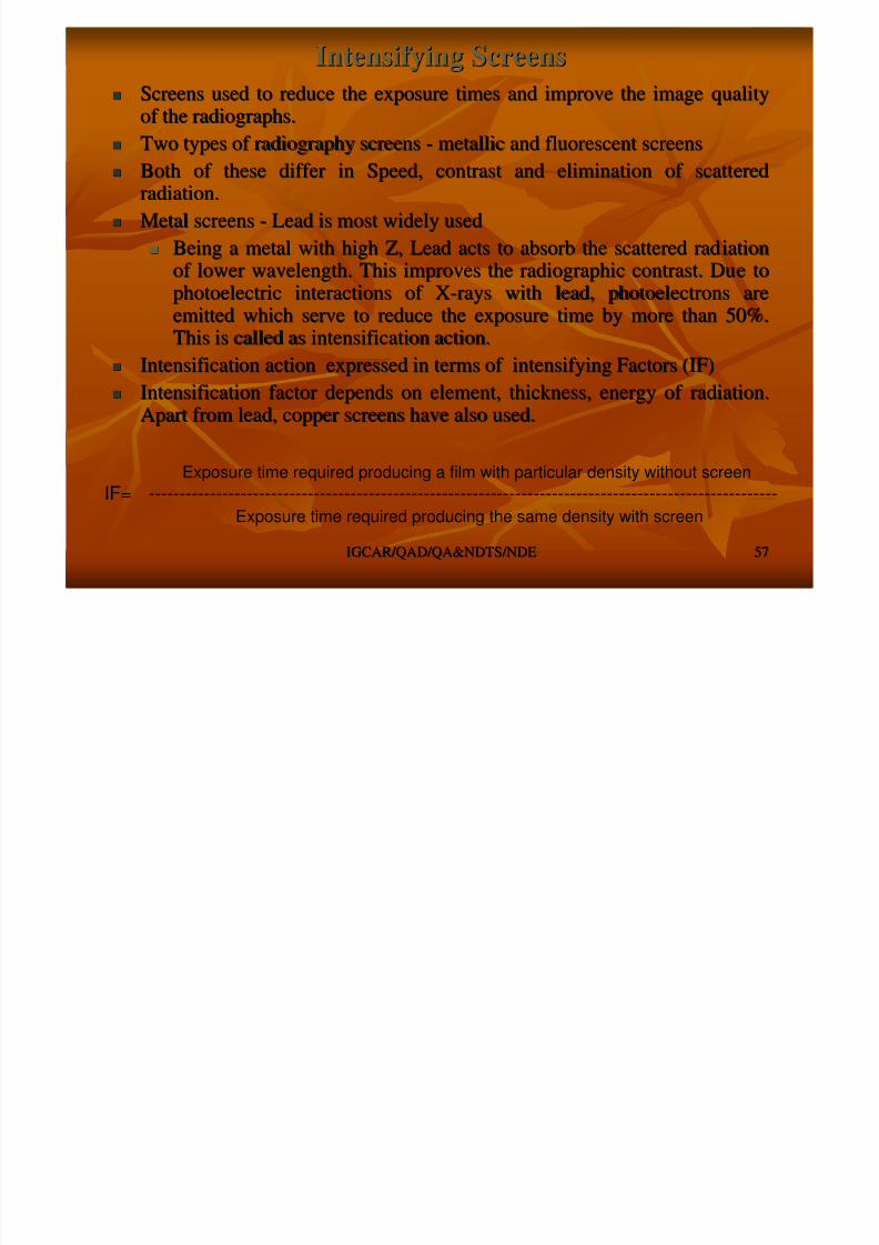
Screens used to reduce the exposure times and improve the imageScreens used to reduce the exposure times and improve the image qualityquality
of the radiographs.of the radiographs. Two types of radiography screensTwo types of radiography screens -- metallic and fluorescent screensmetallic and fluorescent screens
Both of these differ in Speed, contrast and elimination of scattBoth of these differ in Speed, contrast and elimination of scatterederedradiation.radiation.
Metal screensMetal screens
--
Lead is most widely usedLead is most widely used
Being a metal with high Z, Lead acts to absorb the scattered radBeing a metal with high Z, Lead acts to absorb the scattered radiationiationof lower wavelength. This improves the radiographic contrast. Duof lower wavelength. This improves the radiographic contrast. Due toe tophotoelectric interactions of Xphotoelectric interactions of X--rays with lead, photoelectrons arerays with lead, photoelectrons areemitted which serve to reduce the exposure time by more than 50%emitted which serve to reduce the exposure time by more than 50%..
This is called as intensification action.This is called as intensification action. Intensification action expressed in terms of intensifying FactIntensification action expressed in terms of intensifying Factors (IF)ors (IF)
Intensification factor depends on element, thickness, energy of Intensification factor depends on element, thickness, energy of radiation.radiation.Apart from lead, copper screens have also used.Apart from lead, copper screens have also used.
Exposure time required producing a film with particular density without screen
IF= -------------------------------------------------------------------------------------------------------Exposure time required producing the same density with screen
Fluorescent Screens and FiltersFluorescent Screens and Filters

8/4/2019 Non-Destructive Examination 2
http://slidepdf.com/reader/full/non-destructive-examination-2 58/148
IGCAR/QAD/QA&NDTS/NDEIGCAR/QAD/QA&NDTS/NDE 5858
Fluorescent Screens and Filters
Fluorescent or salt screens of calcium tungstate or zinc sulphidFluorescent or salt screens of calcium tungstate or zinc sulphideeprovide greater intensification factor compared to metallic screprovide greater intensification factor compared to metallic screens.ens.However, they are used in medical radiography due to the highHowever, they are used in medical radiography due to the highscreen unsharpness and poor image quality and not in industrialscreen unsharpness and poor image quality and not in industrialradiography.radiography.
Filters are metallic sheets of high atomic number used to absorbFilters are metallic sheets of high atomic number used to absorb thethesoft component of the radiation emanating from the tube port. Fisoft component of the radiation emanating from the tube port. Filtersltersthus harden the radiation beam.thus harden the radiation beam.
The purpose of using filterThe purpose of using filter increase the contrast around the specimen edgeincrease the contrast around the specimen edge
reduce the undercut due to scatter at the edge of thinner sectioreduce the undercut due to scatter at the edge of thinner sectionsnsandand
record a wide range of thickness in a given film.record a wide range of thickness in a given film. Increasing the voltage or time of exposure compensates the lossIncreasing the voltage or time of exposure compensates the loss of of
intensity caused by filter.intensity caused by filter.
Generally filters are made of copper, steel or aluminum.Generally filters are made of copper, steel or aluminum.
RADIOGRAPHIC TECHNIQUESRADIOGRAPHIC TECHNIQUES
8/4/2019 Non-Destructive Examination 2
http://slidepdf.com/reader/full/non-destructive-examination-2 59/148
IGCAR/QAD/QA&NDTS/NDEIGCAR/QAD/QA&NDTS/NDE 5959
RADIOGRAPHIC TECHNIQUESRADIOGRAPHIC TECHNIQUES
Quality of radiographs or detection of discontinuity dependsQuality of radiographs or detection of discontinuity depends
on extent of the optical density of the image.on extent of the optical density of the image.
Selection of exposure parameters required to produce theSelection of exposure parameters required to produce the
required radiographic density to reveal the discontinuityrequired radiographic density to reveal the discontinuity Exposure TimeExposure Time
Exposure TechniqueExposure Technique –– Component / Specimen ShapeComponent / Specimen Shape
Coded Requirements on ImageCoded Requirements on Image Radiographic DensityRadiographic Density
Image QualityImage Quality
RADIOGRAPHIC EXPOSURE TIMERADIOGRAPHIC EXPOSURE TIME
8/4/2019 Non-Destructive Examination 2
http://slidepdf.com/reader/full/non-destructive-examination-2 60/148
IGCAR/QAD/QA&NDTS/NDEIGCAR/QAD/QA&NDTS/NDE 6060
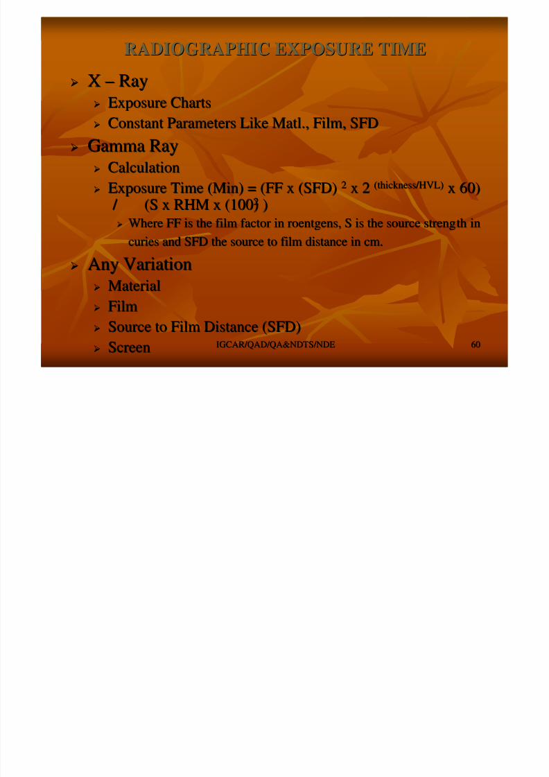
XX –– RayRay Exposure ChartsExposure Charts
Constant Parameters Like Matl., Film, SFDConstant Parameters Like Matl., Film, SFD
Gamma RayGamma Ray CalculationCalculation
Exposure Time (Min) = (FF x (SFD)Exposure Time (Min) = (FF x (SFD) 22 x 2x 2 (thickness/HVL)(thickness/HVL) x 60)x 60)
/ (S x RHM x (100) / (S x RHM x (100)22
))
Where FF is the film factor in roentgens, S is the source strengWhere FF is the film factor in roentgens, S is the source strength inth in
curies and SFD the source to film distance in cm.curies and SFD the source to film distance in cm.
Any VariationAny Variation
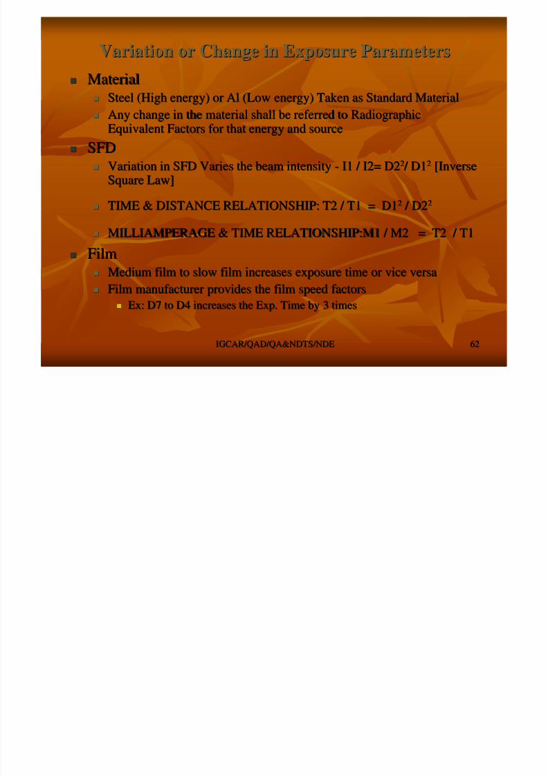
MaterialMaterial
FilmFilm
Source to Film Distance (SFD)Source to Film Distance (SFD)
ScreenScreen
E Ch tE Ch t XX RR
8/4/2019 Non-Destructive Examination 2
http://slidepdf.com/reader/full/non-destructive-examination-2 61/148
IGCAR/QAD/QA&NDTS/NDEIGCAR/QAD/QA&NDTS/NDE 6161
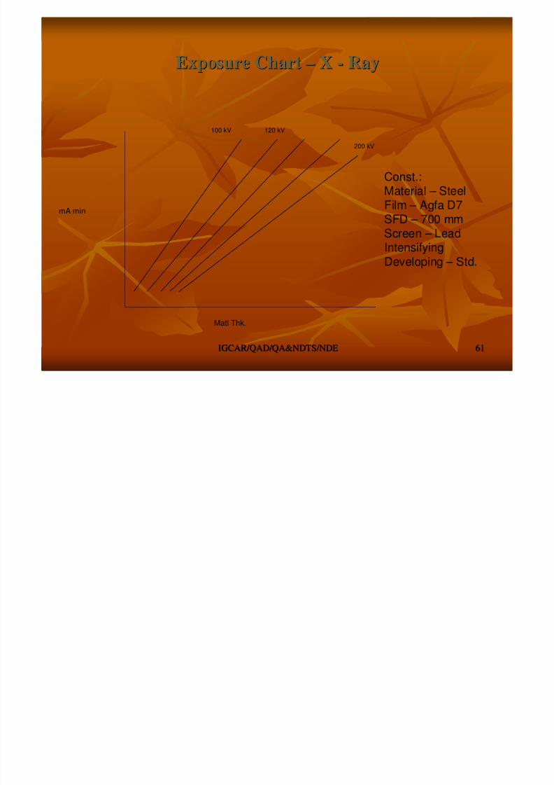
Exposure ChartExposure Chart –– XX -- RayRay
Const.:Material – SteelFilm – Agfa D7
SFD – 700 mmScreen – LeadIntensifying
Developing – Std.
mA min
120 kV100 kV
200 kV
Matl Thk.
8/4/2019 Non-Destructive Examination 2
http://slidepdf.com/reader/full/non-destructive-examination-2 62/148
Selection of Radiographic TechniquesSelection of Radiographic Techniques
Selection of particular radiographic technique is based upon theSelection of particular radiographic technique is based upon the sensitivitysensitivity

8/4/2019 Non-Destructive Examination 2
http://slidepdf.com/reader/full/non-destructive-examination-2 63/148
IGCAR/QAD/QA&NDTS/NDEIGCAR/QAD/QA&NDTS/NDE 6363
Selection of particular radiographic technique is based upon theSelection of particular radiographic technique is based upon the sensitivitysensitivityrequirements.requirements.
Getting information on small discontinuity image is possible onlGetting information on small discontinuity image is possible only with ay with aproper techniqueproper technique
Radiographic technique is affected by radiation source, film usRadiographic technique is affected by radiation source, film used, sources toed, sources tofilm distance andfilm distance and radiation beam alignmentradiation beam alignment
A technique is selected on the basic of the knowledge about theA technique is selected on the basic of the knowledge about the followingfollowingfactors.factors.
Test objectTest object –– materialmaterial -- thickness and configurationthickness and configuration
Fabrication processes (Welds, Casting, Assembly)Fabrication processes (Welds, Casting, Assembly)
Anticipated discontinuities and its locations & orientation,Anticipated discontinuities and its locations & orientation,
Areas of interestAreas of interest Sensitivity level requiredSensitivity level required
Radiographic techniques can be broadly classified asRadiographic techniques can be broadly classified as
High sensitivity technique & Low Sensitivity TechniqueHigh sensitivity technique & Low Sensitivity Technique
Also Classified according to the configuration asAlso Classified according to the configuration as single wall single image (SWSI) techniquesingle wall single image (SWSI) technique
double wall single image (DWSI) techniquedouble wall single image (DWSI) technique
double wall double image (DWDI) techniquedouble wall double image (DWDI) technique
Radiographic TechniquesRadiographic Techniques -- ConfigurationConfiguration
8/4/2019 Non-Destructive Examination 2
http://slidepdf.com/reader/full/non-destructive-examination-2 64/148
IGCAR/QAD/QA&NDTS/NDEIGCAR/QAD/QA&NDTS/NDE 6464
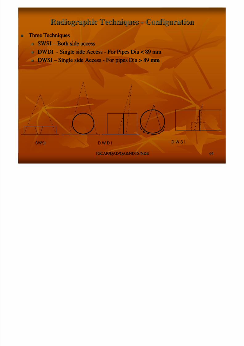
Three TechniquesThree Techniques
SWSISWSI –– Both side accessBoth side access
DWDIDWDI -- Single side AccessSingle side Access -- For Pipes Dia < 89 mmFor Pipes Dia < 89 mm
DWSIDWSI –– Single side AccessSingle side Access -- For pipes Dia > 89 mmFor pipes Dia > 89 mm
SWSI D W D I D W S I
Depth of DiscontinuityDepth of Discontinuity
8/4/2019 Non-Destructive Examination 2
http://slidepdf.com/reader/full/non-destructive-examination-2 65/148
IGCAR/QAD/QA&NDTS/NDEIGCAR/QAD/QA&NDTS/NDE 6565
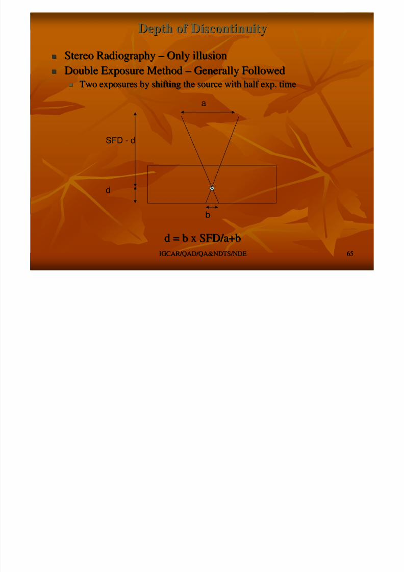
Stereo RadiographyStereo Radiography –– Only illusionOnly illusion Double Exposure MethodDouble Exposure Method –– Generally FollowedGenerally Followed
Two exposures by shifting the source with half exp. timeTwo exposures by shifting the source with half exp. time
d = b x SFD/a+bd = b x SFD/a+b
a
b
SFD - d
d
Film ProcessingFilm Processing
Fil iFil i i fi @ 18i fi t @ 18 2424°° CC
8/4/2019 Non-Destructive Examination 2
http://slidepdf.com/reader/full/non-destructive-examination-2 66/148
IGCAR/QAD/QA&NDTS/NDEIGCAR/QAD/QA&NDTS/NDE 6666
Film processingFilm processing -- in five stages @ 18in five stages @ 18 –– 2424°° CC DevelopingDeveloping
Stop bathStop bath
FixingFixing
Clearing in running waterClearing in running water
DryingDrying The developing converts the exposed silver bromide grains / The developing converts the exposed silver bromide grains /
crystals to metallic silver i.e. creation of the visible imagecrystals to metallic silver i.e. creation of the visible image –– 55MinMin
The second stage stop bath, stops the developing action andThe second stage stop bath, stops the developing action andremoves all the developerremoves all the developer –– 2 Min2 Min
The fixing process fixes this metallic silver and removes allThe fixing process fixes this metallic silver and removes allunexposed silver bromide grains / crystalsunexposed silver bromide grains / crystals –– 10 Min10 Min
Washing in running waterWashing in running water –– 20 Min20 Min The drying dries all the wetness on the film.The drying dries all the wetness on the film.
After drying the film is ready for interpretation.After drying the film is ready for interpretation.
Processing consumes minimum of 30 minutes.Processing consumes minimum of 30 minutes.
Image Quality Indicators (IQI) / PenetrameterImage Quality Indicators (IQI) / Penetrameter
Radiographic sensitivity is judged by the use of Image QualityRadiographic sensitivity is judged by the use of Image Quality
8/4/2019 Non-Destructive Examination 2
http://slidepdf.com/reader/full/non-destructive-examination-2 67/148
IGCAR/QAD/QA&NDTS/NDEIGCAR/QAD/QA&NDTS/NDE 6767
Radiographic sensitivity is judged by the use of Image QualityRadiographic sensitivity is judged by the use of Image Quality
Indicators (IQI)Indicators (IQI) Many type of IQIMany type of IQI -- Plate and Hole, Wire, Step, Step and holePlate and Hole, Wire, Step, Step and hole
Sensitivity assessed by the image of IQI on the radiographSensitivity assessed by the image of IQI on the radiograph
Normally the sensitivity is represented in percentage.Normally the sensitivity is represented in percentage.
Lower the percentage the higher the sensitivityLower the percentage the higher the sensitivity
IQI is selected based on the thickness of specimen to beIQI is selected based on the thickness of specimen to beradiographed and general codes specify IQI thickness equal toradiographed and general codes specify IQI thickness equal to2% of specimen thickness.2% of specimen thickness.
Codes of construction provide the IQI requirementsCodes of construction provide the IQI requirements Sensitivity (plate and hole IQI) = 100/TSensitivity (plate and hole IQI) = 100/T √√[[t x h / 2]t x h / 2]
Sensitivity (wire IQI) = [Dia of minimum wire seenSensitivity (wire IQI) = [Dia of minimum wire seenin radiograph /Specimen Thk. ] x 100in radiograph /Specimen Thk. ] x 100
Generally radiographic sensitivity shall be specified to a levelGenerally radiographic sensitivity shall be specified to a levelof 2%of 2%
IQIIQI

8/4/2019 Non-Destructive Examination 2
http://slidepdf.com/reader/full/non-destructive-examination-2 68/148
IGCAR/QAD/QA&NDTS/NDEIGCAR/QAD/QA&NDTS/NDE
6868
10 Fe 16
10
Wire Step and Hole Plate and Hole
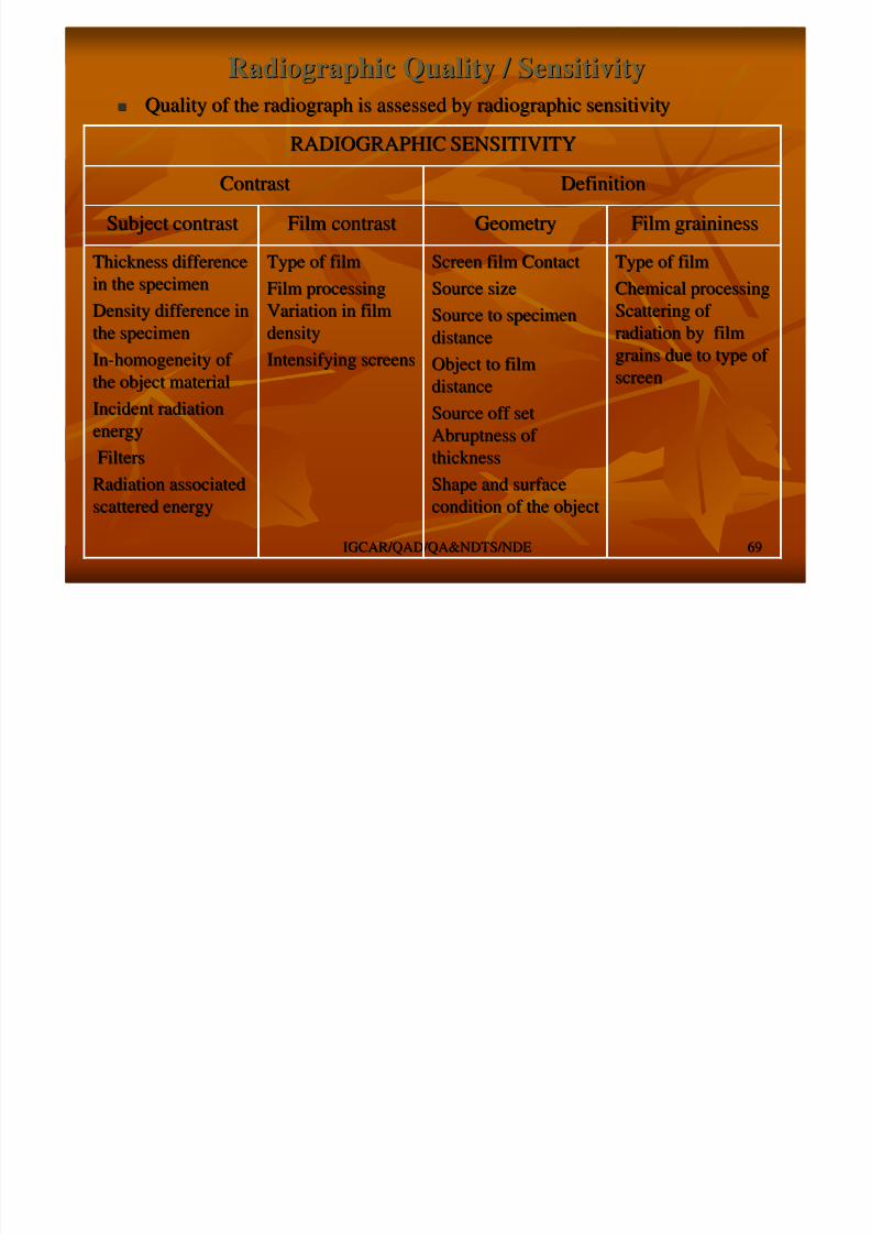
Radiographic Quality / SensitivityRadiographic Quality / Sensitivity
Quality of the radiograph is assessed by radiographic sensitivitQuality of the radiograph is assessed by radiographic sensitivityy
8/4/2019 Non-Destructive Examination 2
http://slidepdf.com/reader/full/non-destructive-examination-2 69/148
IGCAR/QAD/QA&NDTS/NDEIGCAR/QAD/QA&NDTS/NDE
6969
Quality of the radiograph is assessed by radiographic sensitivitQuality of the radiograph is assessed by radiographic sensitivityy
Type of filmType of film
Chemical processingChemical processing
Scattering of Scattering of
radiation by filmradiation by filmgrains due to type of grains due to type of
screenscreen
Screen film ContactScreen film Contact
Source sizeSource size
Source to specimenSource to specimen
distancedistanceObject to filmObject to film
distancedistance
Source off setSource off set
Abruptness of Abruptness of
thicknessthickness
Shape and surfaceShape and surface
condition of the objectcondition of the object
Type of filmType of film
Film processingFilm processing
Variation in filmVariation in film
densitydensityIntensifying screensIntensifying screens
Thickness differenceThickness difference
in the specimenin the specimen
Density difference inDensity difference in
the specimenthe specimenInIn--homogeneity of homogeneity of
the object materialthe object material
Incident radiationIncident radiation
energyenergy
FiltersFilters
Radiation associatedRadiation associated
scattered energyscattered energy
Film graininessFilm graininessGeometryGeometryFilm contrastFilm contrastSubject contrastSubject contrast
DefinitionDefinitionContrastContrast
RADIOGRAPHIC SENSITIVITYRADIOGRAPHIC SENSITIVITY
Evaluation of Radiographs / InterpretationEvaluation of Radiographs / Interpretation
Radiographs inform the presence of discontinuity by theRadiographs inform the presence of discontinuity by the

8/4/2019 Non-Destructive Examination 2
http://slidepdf.com/reader/full/non-destructive-examination-2 70/148
IGCAR/QAD/QA&NDTS/NDEIGCAR/QAD/QA&NDTS/NDE 7070
Radiographs inform the presence of discontinuity by theRadiographs inform the presence of discontinuity by the
radiographic density differenceradiographic density difference Discontinuities are evaluated for its type, location and sizeDiscontinuities are evaluated for its type, location and size
Radiographs provide length and width of the discontinuityRadiographs provide length and width of the discontinuity
Conventional radiography is widely used for the inspection of Conventional radiography is widely used for the inspection of
weldments, casting and complete assembliesweldments, casting and complete assemblies Types of discontinuities vary from process to process likeTypes of discontinuities vary from process to process like
Lack of penetration in the weld, shrinkage in the casting etc.Lack of penetration in the weld, shrinkage in the casting etc.
Type of the discontinuity is arrived from the shape andType of the discontinuity is arrived from the shape and
location of the indicationlocation of the indication Radiographic image are interpreted for acceptance orRadiographic image are interpreted for acceptance or
otherwise of the discontinuity indications depends on the codeotherwise of the discontinuity indications depends on the codeof manufacturing like ASME, BS etc, which is based on theof manufacturing like ASME, BS etc, which is based on the
service requirementsservice requirements
High Energy RadiographyHigh Energy Radiography
8/4/2019 Non-Destructive Examination 2
http://slidepdf.com/reader/full/non-destructive-examination-2 71/148
IGCAR/QAD/QA&NDTS/NDEIGCAR/QAD/QA&NDTS/NDE 7171
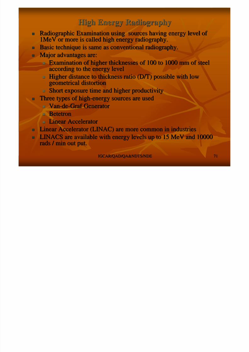
Radiographic Examination using sources having energy level of Radiographic Examination using sources having energy level of 1MeV or more is called high energy radiography.1MeV or more is called high energy radiography.
Basic technique is same as conventional radiography.Basic technique is same as conventional radiography.
Major advantages are:Major advantages are:
Examination of higher thicknesses of 100 to 1000 mm of steelExamination of higher thicknesses of 100 to 1000 mm of steelaccording to the energy levelaccording to the energy level
Higher distance to thickness ratio (D/T) possible with lowHigher distance to thickness ratio (D/T) possible with lowgeometrical distortiongeometrical distortion
Short exposure time and higher productivityShort exposure time and higher productivity
Three types of highThree types of high--energy sources are usedenergy sources are used VanVan--dede--Graf GeneratorGraf Generator
BetetronBetetron
Linear AcceleratorLinear Accelerator
Linear Accelerator (LINAC) are more common in industriesLinear Accelerator (LINAC) are more common in industries LINACS are available with energy levels up to 15 MeV and 10000LINACS are available with energy levels up to 15 MeV and 10000
rads / min out put.rads / min out put.
Advanced radiographic TechniquesAdvanced radiographic Techniques
High Resolution TechniqueHigh Resolution Technique

8/4/2019 Non-Destructive Examination 2
http://slidepdf.com/reader/full/non-destructive-examination-2 72/148
IGCAR/QAD/QA&NDTS/NDEIGCAR/QAD/QA&NDTS/NDE 7272
g qg q
Advancement in areas of electronics and sciences made to obtainAdvancement in areas of electronics and sciences made to obtainvery fine focal in the order of 10very fine focal in the order of 10 µ µ XX –– Ray units.Ray units.
Called as MicroCalled as Micro--Focal Units (having Focal size < 100Focal Units (having Focal size < 100 µ µ ))
Control and very fineControl and very fine--tuning of Xtuning of X--Ray parameters are possibleRay parameters are possible
Allows radiography of components with magnification andAllows radiography of components with magnification andachievement of very high definition and sensitivity (in the ordeachievement of very high definition and sensitivity (in the order of r of 2525 µ µ ).).
This technique enables the examination of very small and intricaThis technique enables the examination of very small and intricatete
components like PCBcomponents like PCB’’s, thin walled (400s, thin walled (400 µ µ ) welds etc.) welds etc. Also these are having Rod Anode type XAlso these are having Rod Anode type X--Ray heads that enables theRay heads that enables the
radiography of tube to tuberadiography of tube to tube--sheet welds of steam generator in thesheet welds of steam generator in thepower industries, which is not possible by conventional radiograpower industries, which is not possible by conventional radiography.phy.
Added advantage of this technique is the adoptability with realAdded advantage of this technique is the adoptability with real timetime
systems.systems. Major limitation is the examination limited to the thicknessMajor limitation is the examination limited to the thickness
according to the kV rating of the unit.according to the kV rating of the unit.
Real Time Radiography (RTR)Real Time Radiography (RTR)Fl / RTR / C t d di h diff f ti l
8/4/2019 Non-Destructive Examination 2
http://slidepdf.com/reader/full/non-destructive-examination-2 73/148
IGCAR/QAD/QA&NDTS/NDEIGCAR/QAD/QA&NDTS/NDE 7373
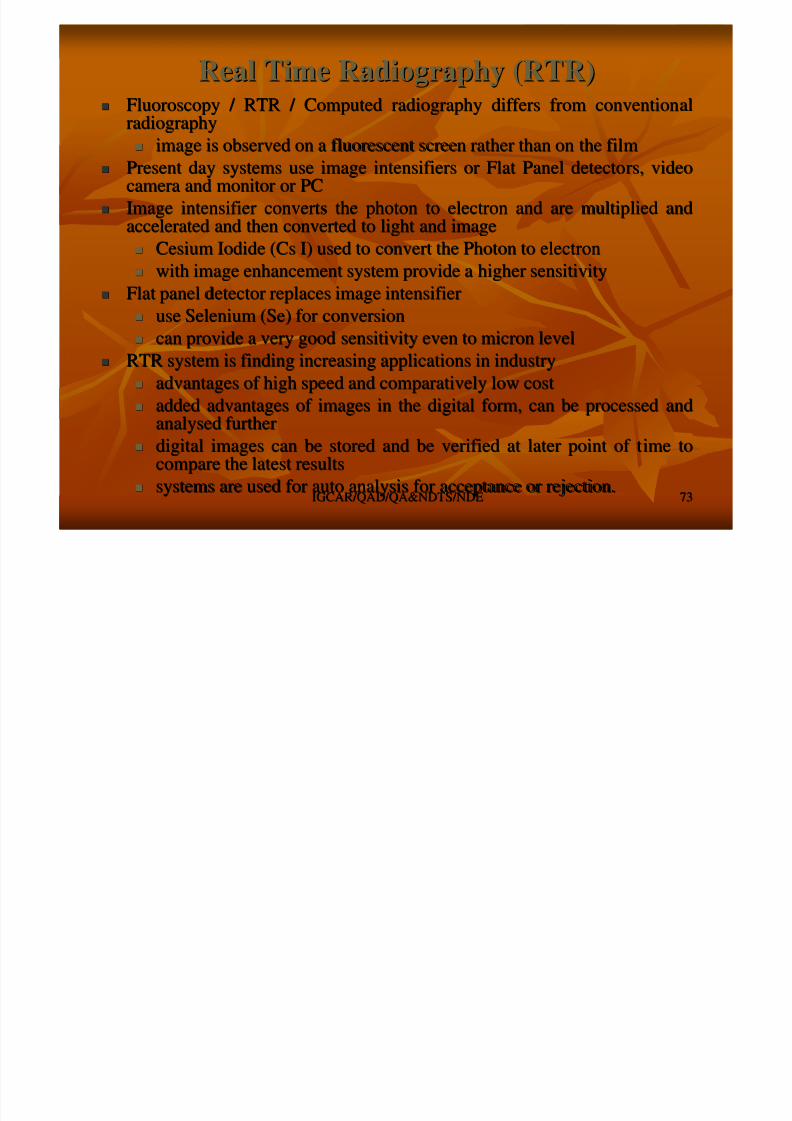
Fluoroscopy / RTR / Computed radiography differs from conventionFluoroscopy / RTR / Computed radiography differs from convention
alal
radiographyradiography
image is observed on a fluorescent screen rather than on the filimage is observed on a fluorescent screen rather than on the filmm
Present day systems use image intensifiers or Flat Panel detectoPresent day systems use image intensifiers or Flat Panel detectors, videors, videocamera and monitor or PCcamera and monitor or PC
Image intensifier converts the photon to electron and are multipImage intensifier converts the photon to electron and are multiplied andlied andaccelerated and then converted to light and imageaccelerated and then converted to light and image
Cesium Iodide (Cs I) used to convert the Photon to electronCesium Iodide (Cs I) used to convert the Photon to electron
with image enhancement system provide a higher sensitivitywith image enhancement system provide a higher sensitivity
Flat panel detector replaces image intensifierFlat panel detector replaces image intensifier
use Selenium (Se) for conversionuse Selenium (Se) for conversion can provide a very good sensitivity even to micron levelcan provide a very good sensitivity even to micron level
RTR system is finding increasing applications in industryRTR system is finding increasing applications in industry
advantages of high speed and comparatively low costadvantages of high speed and comparatively low cost
added advantages of images in the digital form, can be processedadded advantages of images in the digital form, can be processed andandanalysed furtheranalysed further
digital images can be stored and be verified at later point of tdigital images can be stored and be verified at later point of t ime toime tocompare the latest resultscompare the latest results
systems are used for auto analysis for acceptance or rejection.systems are used for auto analysis for acceptance or rejection.
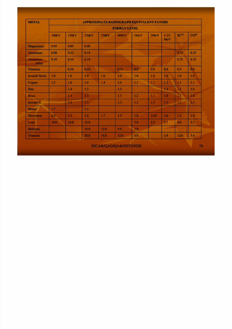
ENERGY LEVELENERGY LEVEL
APPROXIMATE RADIOGRAPH EQUIVALENT FATORSAPPROXIMATE RADIOGRAPH EQUIVALENT FATORSMETALMETAL
8/4/2019 Non-Destructive Examination 2
http://slidepdf.com/reader/full/non-destructive-examination-2 74/148
IGCAR/QAD/QA&NDTS/NDEIGCAR/QAD/QA&NDTS/NDE 7474
3.43.412.612.63.93.94.04.012.012.016.016.020.020.0UraniumUranium
3.03.09.09.012.012.014.014.0HafniumHafnium
2.32.34.04.02.72.72.52.55.05.012.012.014.014.014.014.0LeadLead
1.01.01.21.21.01.014.014.01.01.01.51.51.71.72.02.02.32.32.42.4ZirconiumZirconium
1.21.21.71.7MonelMonel
1.31.31.31.31.31.31.31.31.31.31.31.31.31.31.41.4Inconel XInconel X
1.01.01.11.11.01.01.11.11.21.21.31.31.31.31.41.4BrassBrass
1.01.01.11.11.21.21.31.31.31.31.41.4ZincZinc
1.11.11.11.11.21.21.11.11.11.11.41.41.41.41.41.41.61.61.51.5CopperCopper
1.01.01.01.01.01.01.01.01.01.01.01.01.01.01.01.01.01.01.01.0Iron/all SteelsIron/all Steels
0.90.90.90.90.90.90.90.90.90.90.710.710.540.540.540.54TitaniumTitanium
0.350.350.350.350.180.180.140.140.100.10AluminumAluminum
AlloyAlloy
0.350.350.350.350.180.180.120.120.080.08AluminumAluminum
0.080.080.050.050.050.05MagnesiumMagnesium
COCO6060IRIR19219244--2525
MeVMeV
2MeV2MeV1MeV1MeV400kV400kV250kV250kV220kV220kV150kV150kV100kV100kV
Effects of RadiationEffects of Radiation

8/4/2019 Non-Destructive Examination 2
http://slidepdf.com/reader/full/non-destructive-examination-2 75/148
IGCAR/QAD/QA&NDTS/NDEIGCAR/QAD/QA&NDTS/NDE 7575
Exposure to radiations (x,Exposure to radiations (x, γ γ ,, αα,, ββ)) are hazardousare hazardous Radiations produce ions and modify the cellRadiations produce ions and modify the cell
Natural mechanism of the body rectifies the damagesNatural mechanism of the body rectifies the damages
When this is not successful, irradiation causes the following:When this is not successful, irradiation causes the following:
Chromosome aberrationsChromosome aberrations Gene mutationGene mutation
Cell deathCell death
Radiation effects are depends onRadiation effects are depends on
type of radiationtype of radiation
energy of radiationenergy of radiation
dose & duration of exposuredose & duration of exposure
mode (internal or external)mode (internal or external) region of the body exposed.region of the body exposed.
Radiation monitoring and ControlRadiation monitoring and Control

8/4/2019 Non-Destructive Examination 2
http://slidepdf.com/reader/full/non-destructive-examination-2 76/148
IGCAR/QAD/QA&NDTS/NDEIGCAR/QAD/QA&NDTS/NDE 7676
Data are available on this from experimental studies, medicalData are available on this from experimental studies, medicalexposures, uranium miners, survivors of Hiroshima and Nagasakiexposures, uranium miners, survivors of Hiroshima and Nagasakietcetc
International Committee on Radiological Protection (ICRP) arriveInternational Committee on Radiological Protection (ICRP) arrive atata safe limits of exposure based on these dataa safe limits of exposure based on these data
Whole body radiation limited to 2.0 rem / year is permitted forWhole body radiation limited to 2.0 rem / year is permitted forradiation workers and for general public limited to 0.2 rem/yearradiation workers and for general public limited to 0.2 rem/year
Radiation is invisible, can be detected and monitored using radiRadiation is invisible, can be detected and monitored using radiationationgauges, monitors and survey metersgauges, monitors and survey meters
Instruments are working by the principle of ionizationInstruments are working by the principle of ionizationcharacteristics of radiationcharacteristics of radiation
Radiation workers are monitored by the use of film / TLD badgesRadiation workers are monitored by the use of film / TLD badgesand pocket dosimeters.and pocket dosimeters.
Permanent records are made for the individual radiation workerPermanent records are made for the individual radiation worker
Level of radiation in particular areas ( Area Monitoring)Level of radiation in particular areas ( Area Monitoring) ––Cordoning of areasCordoning of areas
Evaluation of RadiographsEvaluation of Radiographs
Some typical Weld DiscontinuitiesSome typical Weld Discontinuities

8/4/2019 Non-Destructive Examination 2
http://slidepdf.com/reader/full/non-destructive-examination-2 77/148
IGCAR/QAD/QA&NDTS/NDEIGCAR/QAD/QA&NDTS/NDE 7777
Lack of Penetration
Slag inclusion
Porosity
Micro Focal RadiographyMicro Focal Radiography

8/4/2019 Non-Destructive Examination 2
http://slidepdf.com/reader/full/non-destructive-examination-2 78/148
IGCAR/QAD/QA&NDTS/NDEIGCAR/QAD/QA&NDTS/NDE 7878
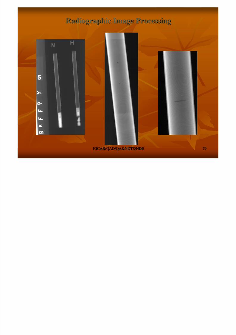
Radiographic Image ProcessingRadiographic Image Processing
8/4/2019 Non-Destructive Examination 2
http://slidepdf.com/reader/full/non-destructive-examination-2 79/148
IGCAR/QAD/QA&NDTS/NDEIGCAR/QAD/QA&NDTS/NDE 7979
8/4/2019 Non-Destructive Examination 2
http://slidepdf.com/reader/full/non-destructive-examination-2 80/148
IGCAR/QAD/QA&NDTS/NDEIGCAR/QAD/QA&NDTS/NDE 8080
ULTRASONIC EXAMINATIONULTRASONIC EXAMINATION
Fundamentals of UltrasonicFundamentals of Ultrasonic
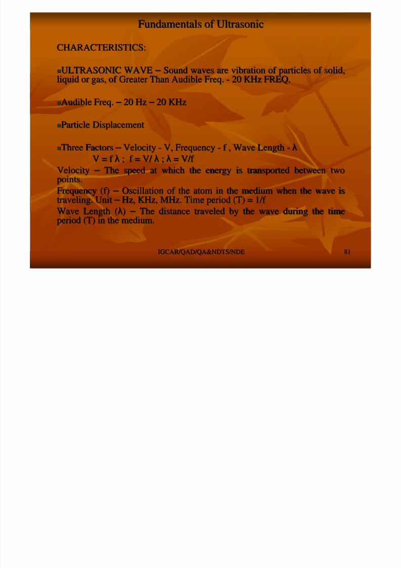
CHARACTERISTICS:CHARACTERISTICS:
8/4/2019 Non-Destructive Examination 2
http://slidepdf.com/reader/full/non-destructive-examination-2 81/148
IGCAR/QAD/QA&NDTS/NDEIGCAR/QAD/QA&NDTS/NDE 8181
ULTRASONIC WAVEULTRASONIC WAVE – – Sound waves are vibration of particles of solid,Sound waves are vibration of particles of solid,liquid or gas, of Greater Than Audible Freq.liquid or gas, of Greater Than Audible Freq. -- 20 KHz FREQ.20 KHz FREQ.
Audible Freq.Audible Freq. – – 20 Hz20 Hz – – 20 KHz20 KHz
Particle DisplacementParticle Displacement
Three FactorsThree Factors – – VelocityVelocity -- V, FrequencyV, Frequency -- f , Wave Lengthf , Wave Length -- λλ
V = f V = f λλ ; f = V/ ; f = V/ λλ ;; λλ = V/f = V/f VelocityVelocity – – The speed at which the energy is transported between twoThe speed at which the energy is transported between twopoints.points.
Frequency (f)Frequency (f) – – Oscillation of the atom in the medium when the wave isOscillation of the atom in the medium when the wave istraveling. Unittraveling. Unit – – Hz, KHz, MHz. Time period (T) = 1/f Hz, KHz, MHz. Time period (T) = 1/f
Wave Length (Wave Length (λλ)) – – The distance traveled by the wave during the timeThe distance traveled by the wave during the timeperiod (T) in the medium.period (T) in the medium.
Fundamentals of UltrasonicFundamentals of Ultrasonic
8/4/2019 Non-Destructive Examination 2
http://slidepdf.com/reader/full/non-destructive-examination-2 82/148
IGCAR/QAD/QA&NDTS/NDEIGCAR/QAD/QA&NDTS/NDE 8282
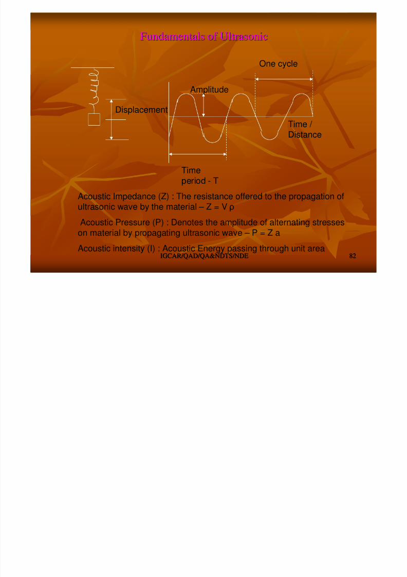
Time
period - T
One cycle
Time / Distance
Amplitude
Displacement
Acoustic Impedance (Z) : The resistance offered to the propagation of
ultrasonic wave by the material – Z = V ρAcoustic Pressure (P) : Denotes the amplitude of alternating stresses
on material by propagating ultrasonic wave – P = Z a
Acoustic intensity (I) : Acoustic Energy passing through unit area
TYPES OF ULTRASONIC WAVESTYPES OF ULTRASONIC WAVES

8/4/2019 Non-Destructive Examination 2
http://slidepdf.com/reader/full/non-destructive-examination-2 83/148
IGCAR/QAD/QA&NDTS/NDEIGCAR/QAD/QA&NDTS/NDE 8383
Longitudinal / Compression WaveLongitudinal / Compression Wave Alternative compression and rarefactionAlternative compression and rarefaction
Particles Vibration parallel to the wave propagationParticles Vibration parallel to the wave propagation
Propagate in all mediaPropagate in all media –– Solid, Liquid and GasSolid, Liquid and Gas
Transverse / Shear WaveTransverse / Shear Wave
Particles Vibration perpendicular to wave propagationParticles Vibration perpendicular to wave propagation
Propagation only in solidsPropagation only in solids
Surface / Raleigh WaveSurface / Raleigh Wave
Particle vibration generally ellipticalParticle vibration generally elliptical
Travel along the surfaceTravel along the surface -- up to one wave length depthup to one wave length depth
Lamb / Plate WaveLamb / Plate Wave
Velocity depends on type of material, material thk., freq.Velocity depends on type of material, material thk., freq.
Complex modesComplex modes
V l = E/ ρ
V t = G/ ρ
V s = 0.9 V t
ACOUSTIC PROPERTIESACOUSTIC PROPERTIES
8/4/2019 Non-Destructive Examination 2
http://slidepdf.com/reader/full/non-destructive-examination-2 84/148
IGCAR/QAD/QA&NDTS/NDEIGCAR/QAD/QA&NDTS/NDE 8484
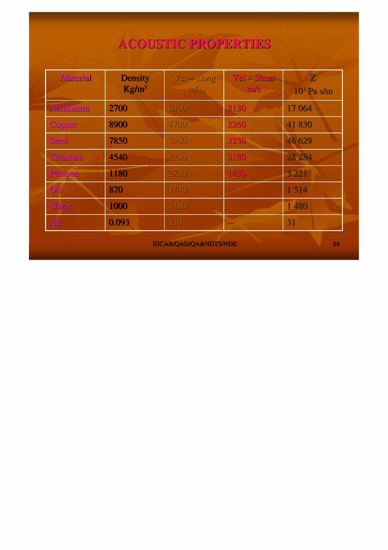
3131----3303300.0930.093AirAir
1 4801 480----1480148010001000WaterWater
1 5141 514----17401740870870OilOil
3 2213 221143014302730273011801180PerspexPerspex
28 28428 284318031806230623045404540TitaniumTitanium
46 62946 629325032505950595078507850SteelSteel
41 83041 830226022604700470089008900CopperCopper
17 06417 064313031306300630027002700AluminumAluminum
ZZ
101033 PaPa s/ms/m
VelVel –– ShearShear
m/sm/s
VelVel –– LongLong
m/sm/s
DensityDensity
Kg/mKg/m33
MaterialMaterial
WAVE PROPAGATIONWAVE PROPAGATION
Transmission, Reflection & RefractionTransmission, Reflection & Refraction
8/4/2019 Non-Destructive Examination 2
http://slidepdf.com/reader/full/non-destructive-examination-2 85/148
IGCAR/QAD/QA&NDTS/NDEIGCAR/QAD/QA&NDTS/NDE 8585
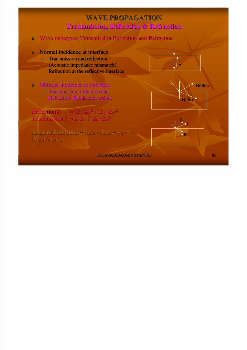
Wave undergoes Transmission Reflection and RefractionWave undergoes Transmission Reflection and Refraction
Normal incidence at interfaceNormal incidence at interface Transmission and reflectionTransmission and reflection
(Acoustic impedance mismatch)(Acoustic impedance mismatch)Refraction at the reflective interfaceRefraction at the reflective interface
Oblique Incidence at interfaceOblique Incidence at interface Transmission, reflection andTransmission, reflection and
Refraction (Mode conversion)Refraction (Mode conversion)
Reflection R = (ZReflection R = (Z11--ZZ22))22 / (Z / (Z11+Z+Z22))22
Transmission T = ZTransmission T = Z11ZZ22 / (Z / (Z11+Z+Z22))22
Angle of Refraction = sin a / sin b = VAngle of Refraction = sin a / sin b = V11 / V / V22
(Snell(Snell’’s Law)s Law)
S
S
L
L
T R
Refra
Reflec
Mode conversion and critical anglesMode conversion and critical anglesWhen the longitudinal wave incident obliquely at interface, insiWhen the longitudinal wave incident obliquely at interface, inside thede the

8/4/2019 Non-Destructive Examination 2
http://slidepdf.com/reader/full/non-destructive-examination-2 86/148
IGCAR/QAD/QA&NDTS/NDEIGCAR/QAD/QA&NDTS/NDE 8686
specimen the beam refracts in to longitudinal and transverse modspecimen the beam refracts in to longitudinal and transverse modes. This ises. This is
calledcalled ““Mode ConversionMode Conversion””..
When the incident angle increased, at one angle the refracted loWhen the incident angle increased, at one angle the refracted longitudinalngitudinal
beam will be gliding on the scanning surface. This is called thebeam will be gliding on the scanning surface. This is called the ““First CriticalFirst Critical
AngleAngle””..
If the incident angle increased further, then at one angle the rIf the incident angle increased further, then at one angle the refracted shear / efracted shear /
transverse beam becomes gliding and is called astransverse beam becomes gliding and is called as ““Surface WaveSurface Wave”” and theand the
angle is called asangle is called as ““Second Critical AngleSecond Critical Angle””..
The angle beam transducers are designed between these critical aThe angle beam transducers are designed between these critical angles tongles to
produce the desired angle.produce the desired angle.
Wave PropagationWave Propagation
Beam Divergence, Near Field, Far FieldBeam Divergence, Near Field, Far Field
Th di bTh di b

8/4/2019 Non-Destructive Examination 2
http://slidepdf.com/reader/full/non-destructive-examination-2 87/148
IGCAR/QAD/QA&NDTS/NDEIGCAR/QAD/QA&NDTS/NDE 8787
The wave propagate as a divergent beamThe wave propagate as a divergent beam
Near FieldNear Field –– Sound Pr. is not uniformSound Pr. is not uniform –– DD22 / 4 / 4λλ Far FieldFar Field -- FraunhauferFraunhaufer ZoneZone –– After Near zoneAfter Near zone
Beam Divergence / SpreadBeam Divergence / Spread –– SinSin θθ = K= K λλ / D / DValue KValue K -- 1.22 (100%1.22 (100%-- 40dB); 1.08 (10%40dB); 1.08 (10% -- 20dB); 0.55 (50%20dB); 0.55 (50%--6dB)6dB)
DD –– Dia of probeDia of probe
NearField Far Field
θ
Attenuation of Ultrasonic BeamAttenuation of Ultrasonic Beam
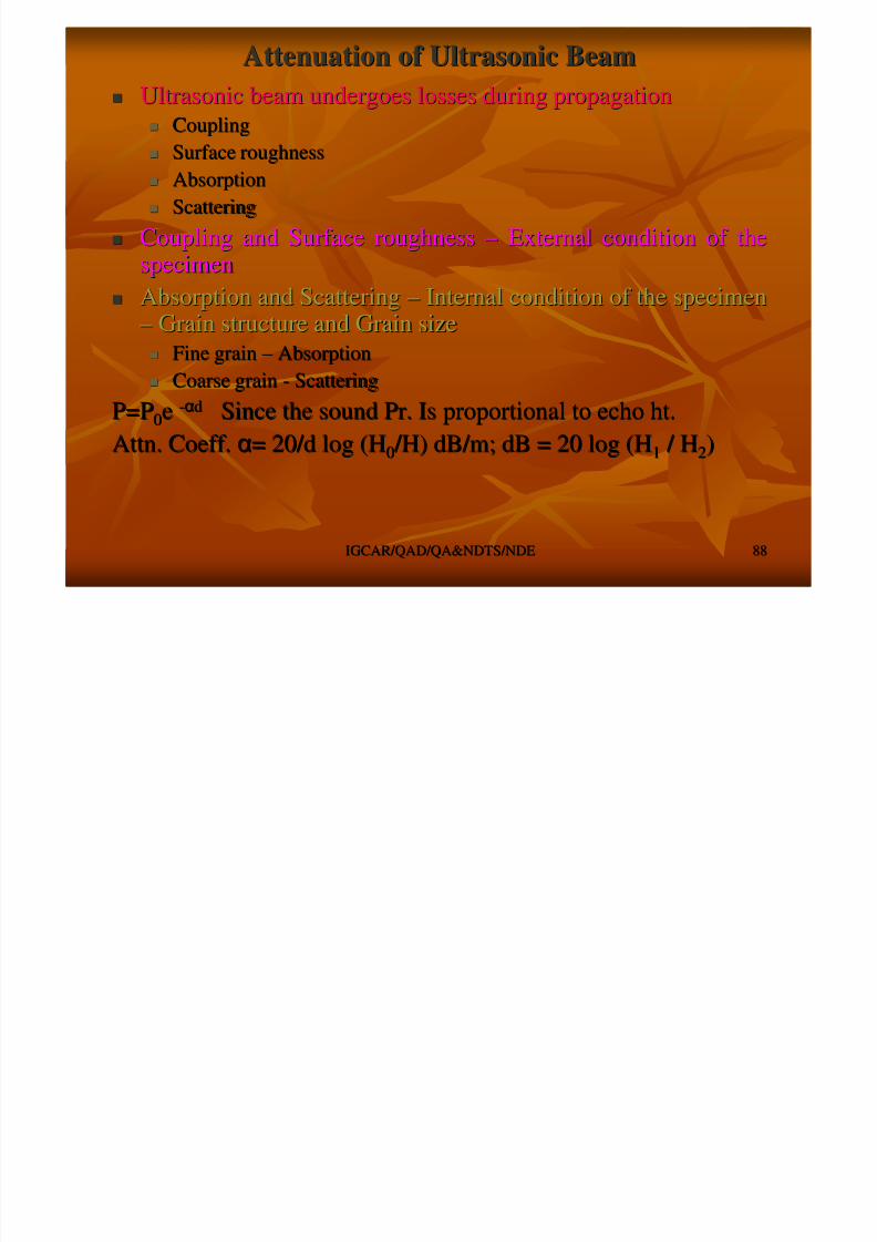
Ultrasonic beam undergoes losses during propagationUltrasonic beam undergoes losses during propagation
C liC li
8/4/2019 Non-Destructive Examination 2
http://slidepdf.com/reader/full/non-destructive-examination-2 88/148
IGCAR/QAD/QA&NDTS/NDEIGCAR/QAD/QA&NDTS/NDE 8888
CouplingCoupling Surface roughnessSurface roughness
AbsorptionAbsorption
ScatteringScattering
Coupling and Surface roughnessCoupling and Surface roughness –– External condition of theExternal condition of thespecimenspecimen
Absorption and ScatteringAbsorption and Scattering –– Internal condition of the specimenInternal condition of the specimen–– Grain structure and Grain sizeGrain structure and Grain size
Fine grainFine grain –– AbsorptionAbsorption
Coarse grainCoarse grain -- ScatteringScattering
P=PP=P00ee --ααdd Since the sound Pr. Is proportional to echo ht.Since the sound Pr. Is proportional to echo ht.
Attn. Coeff.Attn. Coeff. αα= 20/d log (H= 20/d log (H00 /H) dB/m; dB = 20 log (H /H) dB/m; dB = 20 log (H11 / H / H22))

8/4/2019 Non-Destructive Examination 2
http://slidepdf.com/reader/full/non-destructive-examination-2 89/148
Generation of UltrasoundGeneration of Ultrasound MagnetostrictionMagnetostriction –– Ferromagnetic materials like Fe, Ni, CoFerromagnetic materials like Fe, Ni, Co
h th t th l th ( i ) b i d b li ti fh th t th l th ( i ) b i d b li ti f
8/4/2019 Non-Destructive Examination 2
http://slidepdf.com/reader/full/non-destructive-examination-2 90/148
IGCAR/QAD/QA&NDTS/NDEIGCAR/QAD/QA&NDTS/NDE 9090
shows that the length (size) can be varied by application of shows that the length (size) can be varied by application of magnetic field. If alternating mag. field applied this willmagnetic field. If alternating mag. field applied this willvibrate. Hence, the production of ultrasound in the contactvibrate. Hence, the production of ultrasound in the contactspecimenspecimen
Piezoelectric EffectPiezoelectric Effect –– A piezoelectric material will develop anA piezoelectric material will develop anelectrical potential when subjected to mech. Pr..electrical potential when subjected to mech. Pr..
Two types of piezoelectric transducersTwo types of piezoelectric transducers
Single crystalSingle crystal –– Natural / ArtificialNatural / Artificial –– Quartz, Lithium SulphateQuartz, Lithium Sulphate Polycrystalline materialsPolycrystalline materials –– PolarisedPolarised Ceramic MaterialsCeramic Materials -- BariumBarium
Titanate, Lead Zirconate Titanate (PZT), Lead Metabionate.Titanate, Lead Zirconate Titanate (PZT), Lead Metabionate.
These are made by heating them to their curie point and coolingThese are made by heating them to their curie point and cooling themthemunder the influence of voltage.under the influence of voltage.
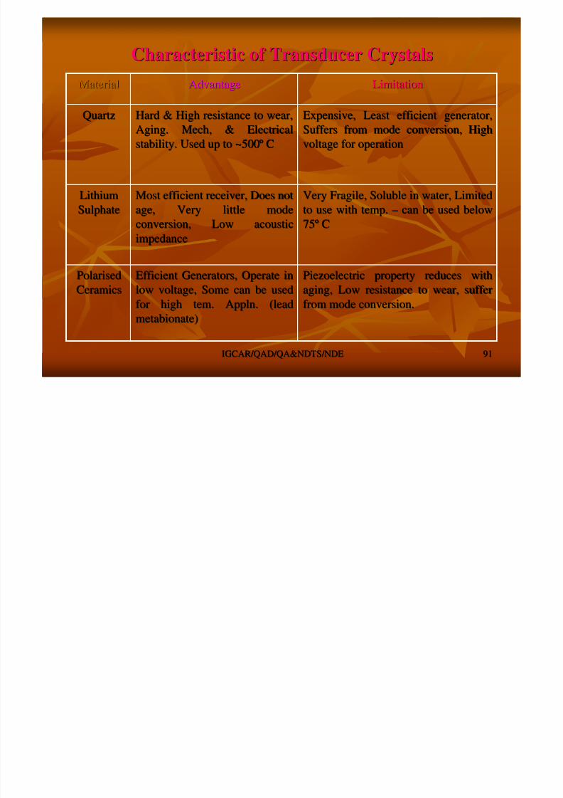
Characteristic of Transducer CrystalsCharacteristic of Transducer Crystals
LimitationLimitationAdvantageAdvantageMaterialMaterial
8/4/2019 Non-Destructive Examination 2
http://slidepdf.com/reader/full/non-destructive-examination-2 91/148
IGCAR/QAD/QA&NDTS/NDEIGCAR/QAD/QA&NDTS/NDE 9191
Piezoelectric property reduces withPiezoelectric property reduces with
aging, Low resistance to wear, sufferaging, Low resistance to wear, sufferfrom mode conversion.from mode conversion.
Efficient Generators, Operate inEfficient Generators, Operate in
low voltage, Some can be usedlow voltage, Some can be usedfor high tem. Appln. (leadfor high tem. Appln. (lead
metabionate)metabionate)
PolarisedPolarised
CeramicsCeramics
Very Fragile, Soluble in water, LimitedVery Fragile, Soluble in water, Limited
to use with temp.to use with temp. –– can be used belowcan be used below
7575ºº CC
Most efficient receiver, Does notMost efficient receiver, Does not
age, Very little modeage, Very little mode
conversion, Low acousticconversion, Low acousticimpedanceimpedance
LithiumLithium
SulphateSulphate
Expensive, Least efficient generator,Expensive, Least efficient generator,
Suffers from mode conversion, HighSuffers from mode conversion, High
voltage for operationvoltage for operation
Hard & High resistance to wear,Hard & High resistance to wear,
Aging. Mech, & ElectricalAging. Mech, & Electrical
stability. Used up to ~500stability. Used up to ~500ºº CC
QuartzQuartz
LimitationLimitationAdvantageAdvantageMaterialMaterial
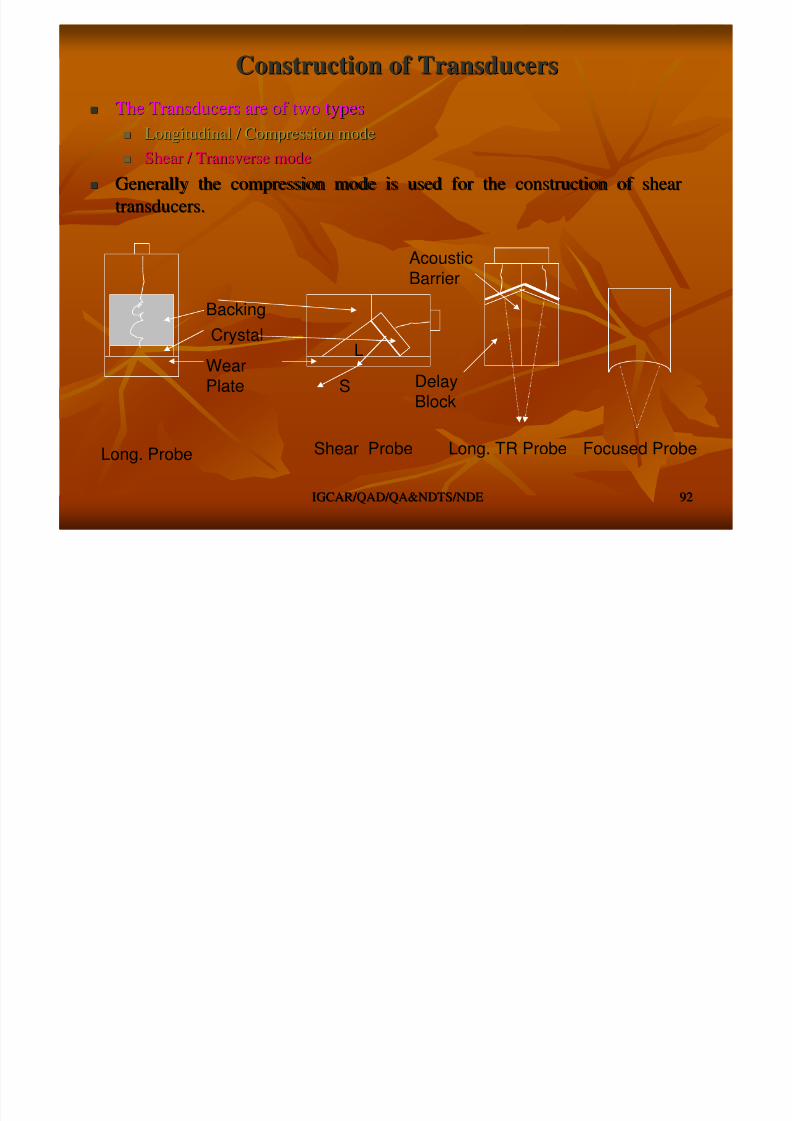
Construction of TransducersConstruction of Transducers
The Transducers are of two typesThe Transducers are of two types
8/4/2019 Non-Destructive Examination 2
http://slidepdf.com/reader/full/non-destructive-examination-2 92/148
IGCAR/QAD/QA&NDTS/NDEIGCAR/QAD/QA&NDTS/NDE 9292
Longitudinal / Compression modeLongitudinal / Compression mode
Shear / Transverse modeShear / Transverse mode
Generally the compression mode is used for the construction of sGenerally the compression mode is used for the construction of shearhear
transducers.transducers.
WearPlate
CrystalBacking
L
S
Acoustic
Barrier
DelayBlock
Long. Probe Shear Probe Long. TR Probe Focused Probe
CouplantCouplant
Air is having low acoustic impedance compared to the probe and tAir is having low acoustic impedance compared to the probe and thehe
8/4/2019 Non-Destructive Examination 2
http://slidepdf.com/reader/full/non-destructive-examination-2 93/148
IGCAR/QAD/QA&NDTS/NDEIGCAR/QAD/QA&NDTS/NDE 9393
Air is having low acoustic impedance compared to the probe and tAir is having low acoustic impedance compared to the probe and thehespecimen. Hence the beam is reflected at the probe specimenspecimen. Hence the beam is reflected at the probe specimeninterface.interface.
A medium with the acoustic impedance between the specimen andA medium with the acoustic impedance between the specimen and
probe has to be usedprobe has to be used Commonly used CouplantCommonly used Couplant
Water, Oils, Glycerin, Petroleum Grease, Silicon GreaseWater, Oils, Glycerin, Petroleum Grease, Silicon Grease
Selection of Couplant based onSelection of Couplant based on
Surface finish, Specimen Temperature, Chemical reaction with theSurface finish, Specimen Temperature, Chemical reaction with thespecimen, Post Cleaningspecimen, Post Cleaning
Transfer correction (ExternalTransfer correction (External condncondn. Of . Of specnspecn.).)
Loss due to surface roughness, Couplant thicknessLoss due to surface roughness, Couplant thickness
Amt. of gain difference between the specimen and reference, in dAmt. of gain difference between the specimen and reference, in dB to beB to beadded during scanningadded during scanning
8/4/2019 Non-Destructive Examination 2
http://slidepdf.com/reader/full/non-destructive-examination-2 94/148

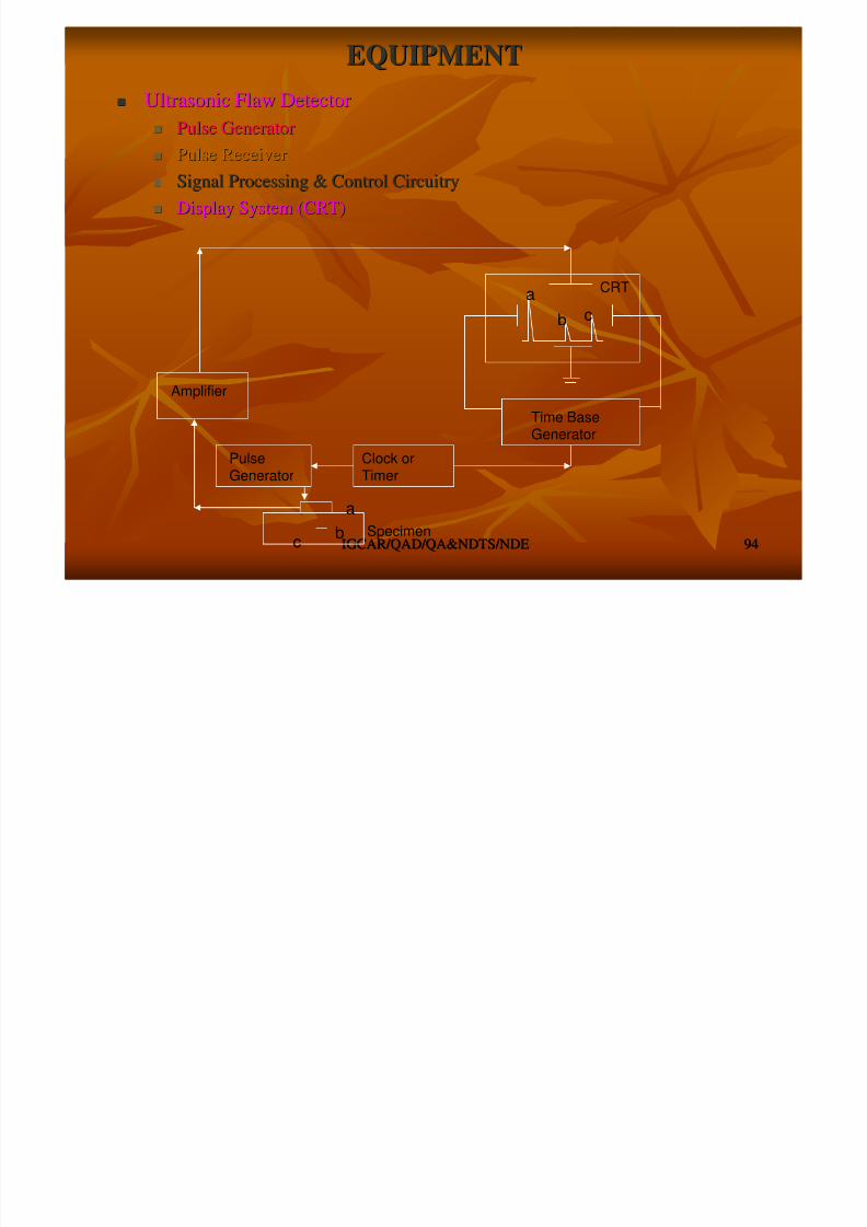
8/4/2019 Non-Destructive Examination 2
http://slidepdf.com/reader/full/non-destructive-examination-2 95/148

8/4/2019 Non-Destructive Examination 2
http://slidepdf.com/reader/full/non-destructive-examination-2 96/148
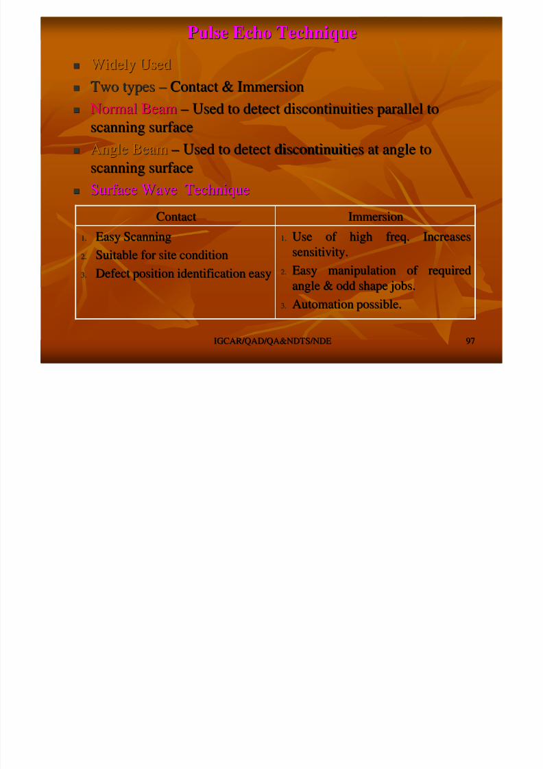
Pulse Echo TechniquePulse Echo Technique
Widely UsedWidely Used
Two typesTwo types –– Contact & ImmersionContact & Immersion
8/4/2019 Non-Destructive Examination 2
http://slidepdf.com/reader/full/non-destructive-examination-2 97/148
IGCAR/QAD/QA&NDTS/NDEIGCAR/QAD/QA&NDTS/NDE 9797
Two typesTwo types Contact & ImmersionContact & Immersion
Normal BeamNormal Beam –– Used to detect discontinuities parallel toUsed to detect discontinuities parallel to
scanning surfacescanning surface
Angle BeamAngle Beam –– Used to detect discontinuities at angle toUsed to detect discontinuities at angle toscanning surfacescanning surface
Surface Wave TechniqueSurface Wave Technique
1.1. Use of high freq. IncreasesUse of high freq. Increases
sensitivity.sensitivity.
2.2. Easy manipulation of requiredEasy manipulation of required
angle & odd shape jobs.angle & odd shape jobs.
3.3. Automation possible.Automation possible.
1.1. Easy ScanningEasy Scanning
2.2. Suitable for site conditionSuitable for site condition
3.3. Defect position identification easyDefect position identification easy
ImmersionImmersionContactContact

8/4/2019 Non-Destructive Examination 2
http://slidepdf.com/reader/full/non-destructive-examination-2 98/148

8/4/2019 Non-Destructive Examination 2
http://slidepdf.com/reader/full/non-destructive-examination-2 99/148
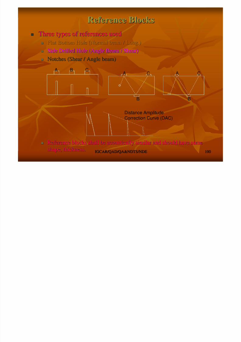
Reference BlocksReference Blocks
Three types of references usedThree types of references usedFlat Bottom Hole (Normal beam / Long )Flat Bottom Hole (Normal beam / Long )
8/4/2019 Non-Destructive Examination 2
http://slidepdf.com/reader/full/non-destructive-examination-2 100/148
IGCAR/QAD/QA&NDTS/NDEIGCAR/QAD/QA&NDTS/NDE 100100
ypyp Flat Bottom Hole (Normal beam / Long.)Flat Bottom Hole (Normal beam / Long.)
Side Drilled Hole (Angle Beam / Shear)Side Drilled Hole (Angle Beam / Shear)
Notches (Shear / Angle beam)Notches (Shear / Angle beam)
Reference blocks shall be acoustically similar and should have sReference blocks shall be acoustically similar and should have sameame
shape, thickness.shape, thickness.
BA C
B
C
B
CAA
Distance AmplitudeCorrection Curve (DAC)
Flaw Sizing and CharacterisationFlaw Sizing and Characterisation
Scanning techniqueScanning technique –– Probe movement to determine theProbe movement to determine thedi ti itdi ti it ’’ L ti L th d O i t tiL ti L th d O i t ti

8/4/2019 Non-Destructive Examination 2
http://slidepdf.com/reader/full/non-destructive-examination-2 101/148
IGCAR/QAD/QA&NDTS/NDEIGCAR/QAD/QA&NDTS/NDE 101101
g qg qdiscontinuitydiscontinuity’’s Location, Length and Orientations Location, Length and Orientation
Ultrasonic Signal gives the information about theUltrasonic Signal gives the information about the
discontinuitydiscontinuity’’s Characterisation / Types Characterisation / Type
Sharp High Ampl. SignalSharp High Ampl. Signal –– Planar type of discontinuityPlanar type of discontinuity
Wide Low Ampl. SignalWide Low Ampl. Signal –– Volumetric Type of discontinuityVolumetric Type of discontinuity
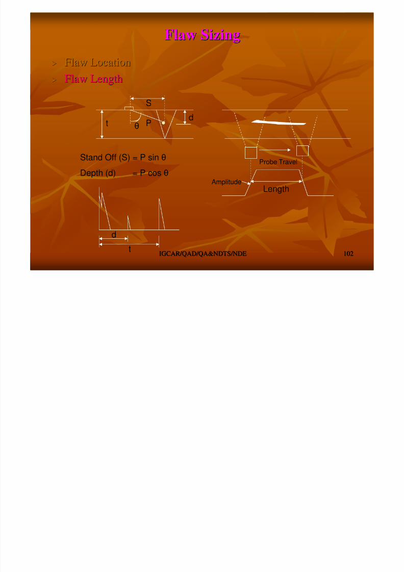
8/4/2019 Non-Destructive Examination 2
http://slidepdf.com/reader/full/non-destructive-examination-2 102/148
8/4/2019 Non-Destructive Examination 2
http://slidepdf.com/reader/full/non-destructive-examination-2 103/148

8/4/2019 Non-Destructive Examination 2
http://slidepdf.com/reader/full/non-destructive-examination-2 104/148
PLATEPLATE
Scanning on any major surface of plateScanning on any major surface of plate
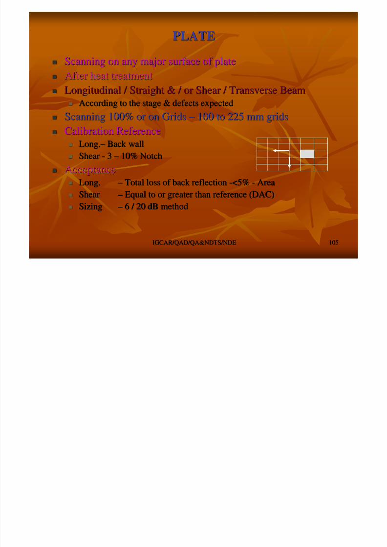
8/4/2019 Non-Destructive Examination 2
http://slidepdf.com/reader/full/non-destructive-examination-2 105/148
IGCAR/QAD/QA&NDTS/NDEIGCAR/QAD/QA&NDTS/NDE 105105
After heat treatmentAfter heat treatment
Longitudinal / Straight & / or Shear / Transverse BeamLongitudinal / Straight & / or Shear / Transverse Beam
According to the stage & defects expectedAccording to the stage & defects expected Scanning 100% or on GridsScanning 100% or on Grids –– 100 to 225 mm grids100 to 225 mm grids
Calibration ReferenceCalibration Reference
Long.Long.–– Back wallBack wall
ShearShear -- 33 –– 10% Notch10% Notch
AcceptanceAcceptance
Long.Long. –– Total loss of back reflectionTotal loss of back reflection --<5%<5% -- AreaArea
ShearShear –– Equal to or greater than reference (DAC)Equal to or greater than reference (DAC)
SizingSizing –– 6 / 20 dB method6 / 20 dB method
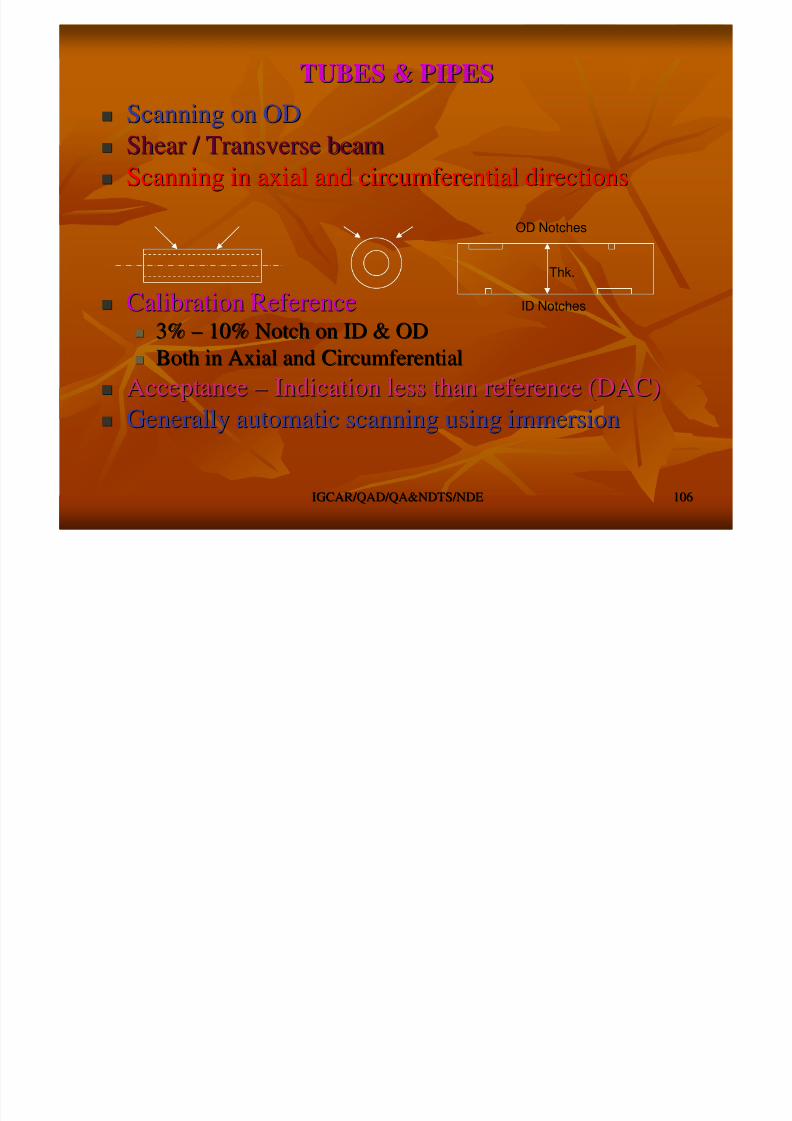
8/4/2019 Non-Destructive Examination 2
http://slidepdf.com/reader/full/non-destructive-examination-2 106/148
FORGINGFORGING
DISC ForgingDISC Forging Straight beamStraight beam –– AxialAxial -- Flat face & RadialFlat face & Radial –– Thk.Thk.
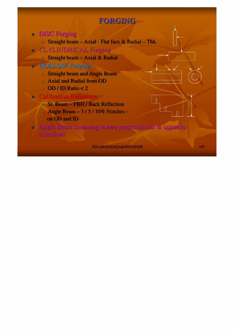
8/4/2019 Non-Destructive Examination 2
http://slidepdf.com/reader/full/non-destructive-examination-2 107/148
IGCAR/QAD/QA&NDTS/NDEIGCAR/QAD/QA&NDTS/NDE 107107
S a g ag a a a a a
CLYLINDRICAL ForgingCLYLINDRICAL Forging
Straight beamStraight beam –– Axial & RadialAxial & Radial
HOLLOW ForgingHOLLOW Forging Straight beam and Angle BeamStraight beam and Angle Beam
Axial and Radial from ODAxial and Radial from OD
OD / ID Ratio < 2OD / ID Ratio < 2
Calibration ReferenceCalibration Reference St. BeamSt. Beam –– FBH / Back ReflectionFBH / Back Reflection
Angle BeamAngle Beam –– 3 / 5 / 10% Notches3 / 5 / 10% Notches ––
on OD and IDon OD and ID
Angle Beam Scanning in two perpendicular & oppositeAngle Beam Scanning in two perpendicular & oppositedirectionsdirections
T
CASTINGCASTING
Low FrequencyLow Frequency –– 0.50.5 –– 2 MHz2 MHz Reference blocks with FBHReference blocks with FBH

8/4/2019 Non-Destructive Examination 2
http://slidepdf.com/reader/full/non-destructive-examination-2 108/148
IGCAR/QAD/QA&NDTS/NDEIGCAR/QAD/QA&NDTS/NDE 108108
Reference blocks with FBHReference blocks with FBH
Surface conditionSurface condition -- RoughRough
To be machined to accommodate scanningTo be machined to accommodate scanning
Amplitude correctionAmplitude correction
Difficulty exist in ultrasonic examinationDifficulty exist in ultrasonic examination
Coarse grain structureCoarse grain structure
Lower S/N RatioLower S/N Ratio
Different configuration and shapeDifferent configuration and shape
DAC
WELDSWELDS
Parent metalParent metal Weld Joint configurationWeld Joint configuration

8/4/2019 Non-Destructive Examination 2
http://slidepdf.com/reader/full/non-destructive-examination-2 109/148
IGCAR/QAD/QA&NDTS/NDEIGCAR/QAD/QA&NDTS/NDE 109109
Weld Joint configurationWeld Joint configuration
Welding ProcessWelding Process
Weld DiscontinuitiesWeld Discontinuities Code, Specification & ProcedureCode, Specification & Procedure
Equipment, Transducer & CalibrationEquipment, Transducer & Calibration
Examination method / TechniqueExamination method / Technique
ReferenceReference
Scanning sequenceScanning sequence
SignalSignal
Evaluation & ReportingEvaluation & Reporting
UE OF WELDUE OF WELD -- BASE METALBASE METAL
Carbon SteelCarbon Steel
Alloy steelAlloy steel

8/4/2019 Non-Destructive Examination 2
http://slidepdf.com/reader/full/non-destructive-examination-2 110/148
IGCAR/QAD/QA&NDTS/NDEIGCAR/QAD/QA&NDTS/NDE 110110
yy
Stainless SteelStainless Steel
Combination of CS, SS & Alloy steelCombination of CS, SS & Alloy steel
AluminumAluminum
Titanium, Copper etc.Titanium, Copper etc.
Similar / DissimilarSimilar / Dissimilar
Thk. of metal joinedThk. of metal joined
AttenuationAttenuation
Velocity of propagationVelocity of propagation
ImpedanceImpedance Heat TreatmentHeat Treatment
MachiningMachining
UE OF WELDUE OF WELD ––
GEOMETRIES/CONFIGURATIONGEOMETRIES/CONFIGURATION
LapLap
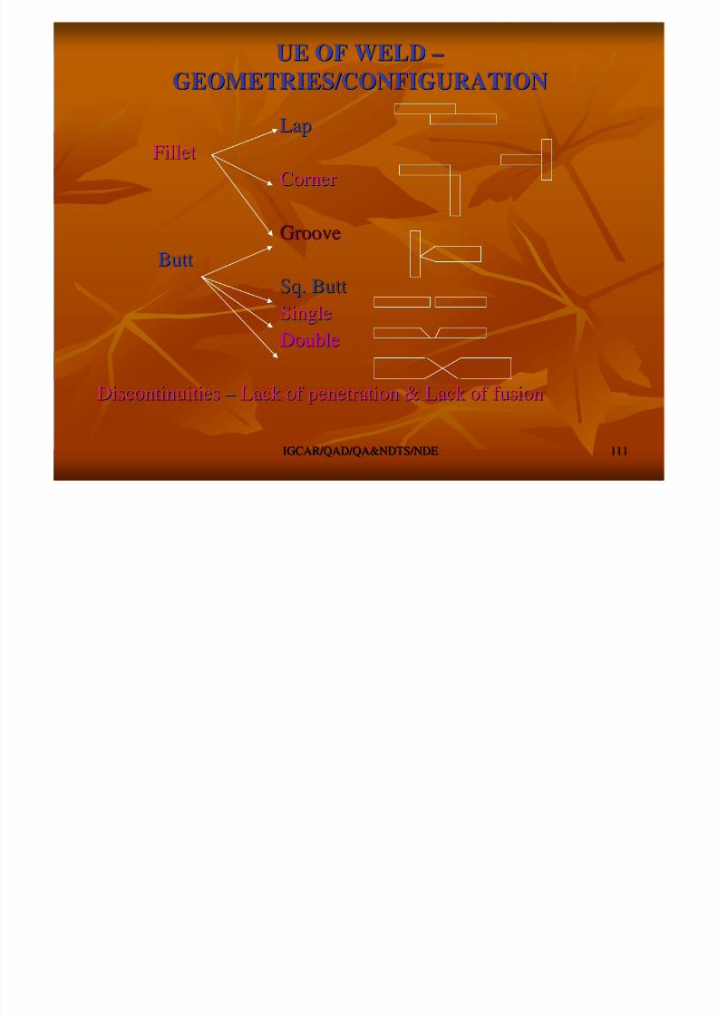
8/4/2019 Non-Destructive Examination 2
http://slidepdf.com/reader/full/non-destructive-examination-2 111/148
IGCAR/QAD/QA&NDTS/NDEIGCAR/QAD/QA&NDTS/NDE 111111
FilletFillet
CornerCorner
GrooveGroove
ButtButt
Sq. ButtSq. ButtSingleSingle
DoubleDouble
DiscontinuitiesDiscontinuities –– Lack of penetration & Lack of fusionLack of penetration & Lack of fusion

8/4/2019 Non-Destructive Examination 2
http://slidepdf.com/reader/full/non-destructive-examination-2 112/148
UE OF WELDUE OF WELD -- DISCONTINUITIESDISCONTINUITIES
TypeType
PlanarPlanar -- Crack, LP, LF, Under Cut, DebondingCrack, LP, LF, Under Cut, Debonding VolumetricVolumetric -- Slag, Porosity, T/ISlag, Porosity, T/I

8/4/2019 Non-Destructive Examination 2
http://slidepdf.com/reader/full/non-destructive-examination-2 113/148
IGCAR/QAD/QA&NDTS/NDEIGCAR/QAD/QA&NDTS/NDE 113113
OriginOrigin
Process parametersProcess parameters –– Current, Speed, Heat input, Heat treatmentCurrent, Speed, Heat input, Heat treatment
Joint configurationJoint configuration Welder performanceWelder performance –– Manipulation, weavingManipulation, weaving
OrientationOrientation
Joint configurationJoint configuration
Weld configuration ( Passes / layers)Weld configuration ( Passes / layers)
Inductance / OccurrenceInductance / Occurrence
Fabrication / ManufacturingFabrication / Manufacturing –– AllAll
InIn--serviceservice –– PlanarPlanar –– Crack Crack
LocationLocation
Anywhere in the weld, HAZ, Parent metalAnywhere in the weld, HAZ, Parent metal
UE OF WELDUE OF WELD -- EXMINATIONEXMINATION
Examination techniqueExamination technique –– Contact, Immersion, IntensityContact, Immersion, Intensity
EquipmentEquipment TransducerTransducer
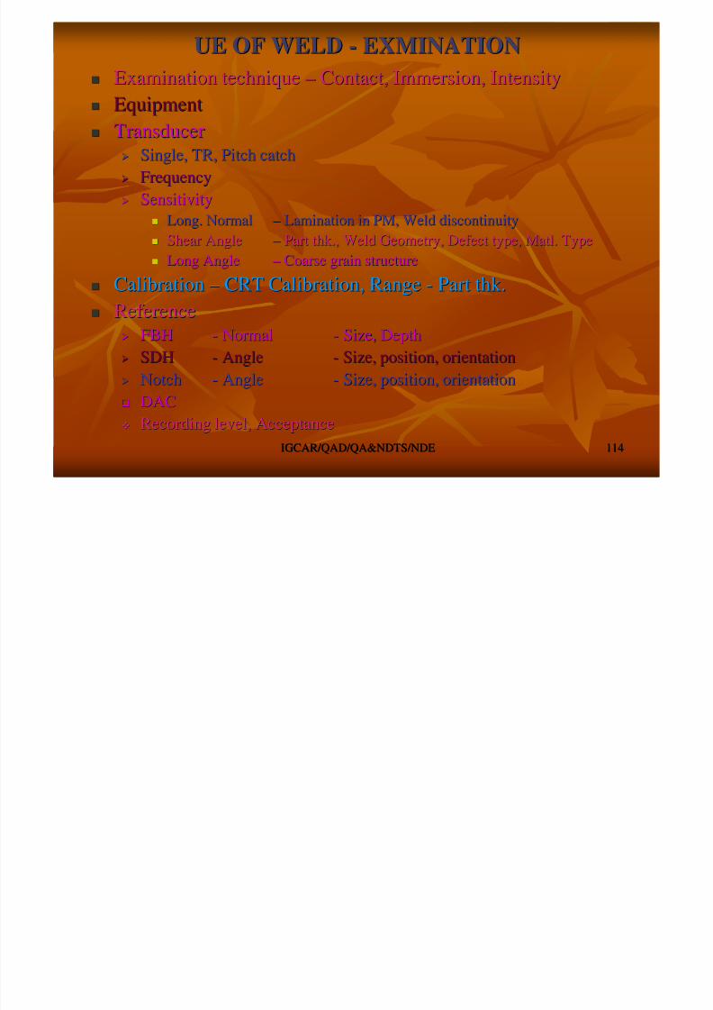
8/4/2019 Non-Destructive Examination 2
http://slidepdf.com/reader/full/non-destructive-examination-2 114/148
IGCAR/QAD/QA&NDTS/NDEIGCAR/QAD/QA&NDTS/NDE 114114
Single, TR, Pitch catchSingle, TR, Pitch catch
FrequencyFrequency
SensitivitySensitivity Long. NormalLong. Normal –– Lamination in PM, Weld discontinuityLamination in PM, Weld discontinuity
Shear AngleShear Angle –– Part thk., Weld Geometry, Defect type, Matl. TypePart thk., Weld Geometry, Defect type, Matl. Type
Long AngleLong Angle –– Coarse grain structureCoarse grain structure
CalibrationCalibration –– CRT Calibration, RangeCRT Calibration, Range -- Part thk.Part thk. ReferenceReference
FBHFBH -- NormalNormal -- Size, DepthSize, Depth
SDHSDH -- AngleAngle -- Size, position, orientationSize, position, orientation
NotchNotch -- AngleAngle -- Size, position, orientationSize, position, orientation DACDAC
Recording level, AcceptanceRecording level, Acceptance
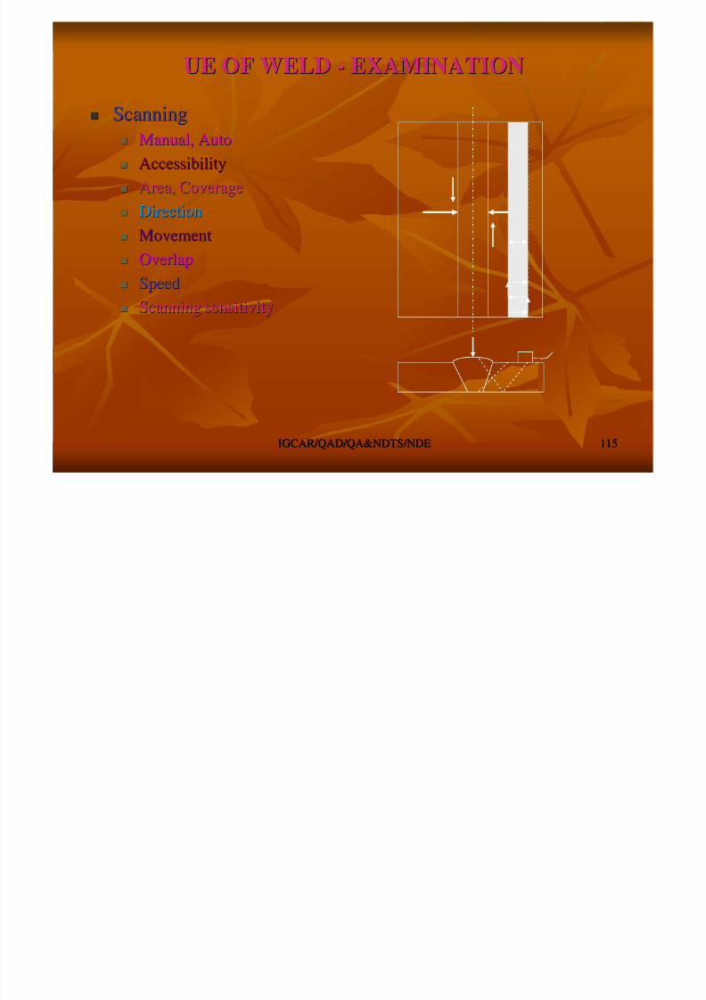
8/4/2019 Non-Destructive Examination 2
http://slidepdf.com/reader/full/non-destructive-examination-2 115/148

8/4/2019 Non-Destructive Examination 2
http://slidepdf.com/reader/full/non-destructive-examination-2 116/148
Discontinuity RepresentationDiscontinuity Representation
Pl
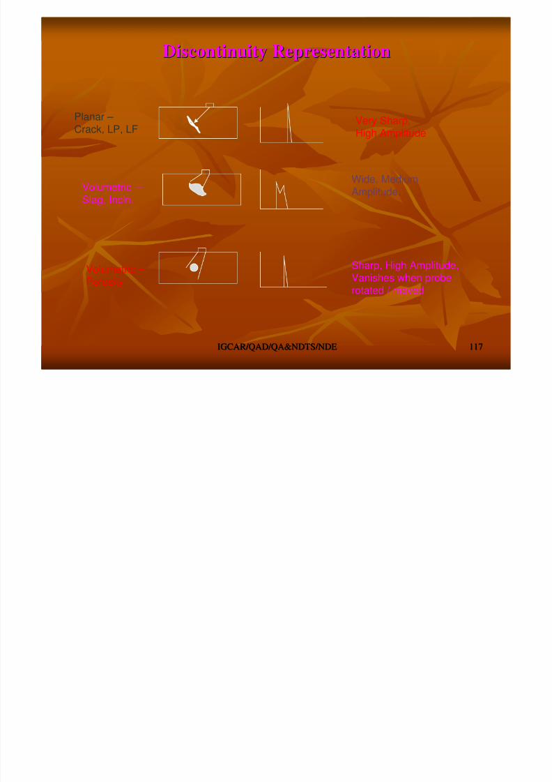
8/4/2019 Non-Destructive Examination 2
http://slidepdf.com/reader/full/non-destructive-examination-2 117/148
IGCAR/QAD/QA&NDTS/NDEIGCAR/QAD/QA&NDTS/NDE 117117
Planar – Crack, LP, LF
Very Sharp,High Amplitude
Volumetric – Slag, Incln.
Wide, MediumAmplitude.
Volumetric – Porosity
Sharp, High Amplitude,Vanishes when probe
rotated / moved
Other TechniquesOther Techniques
Tandem TechniqueTandem Technique
PitchPitch CatchCatch
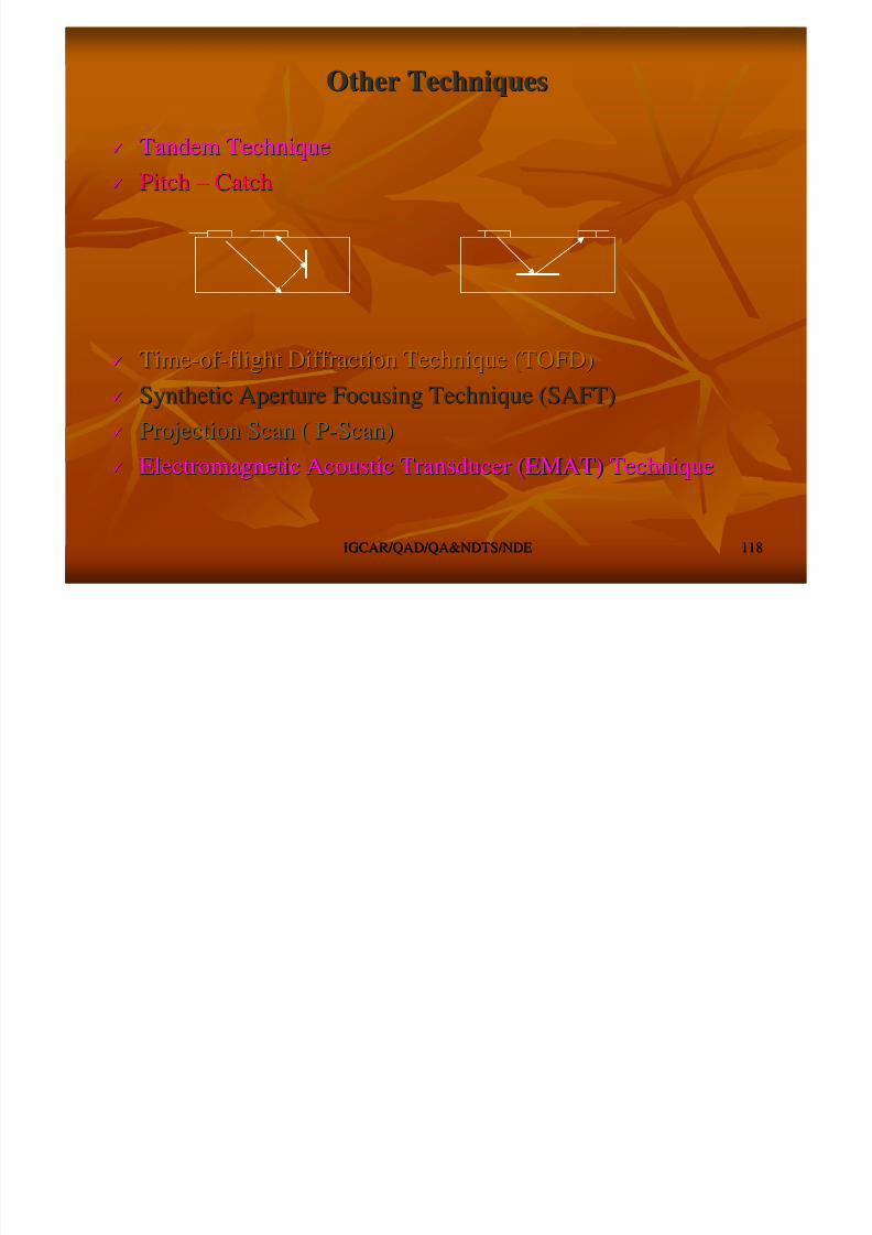
8/4/2019 Non-Destructive Examination 2
http://slidepdf.com/reader/full/non-destructive-examination-2 118/148
IGCAR/QAD/QA&NDTS/NDEIGCAR/QAD/QA&NDTS/NDE 118118
PitchPitch –– CatchCatch
TimeTime--of of --flight Diffraction Technique (TOFD)flight Diffraction Technique (TOFD)
Synthetic Aperture Focusing Technique (SAFT)Synthetic Aperture Focusing Technique (SAFT)
Projection Scan ( PProjection Scan ( P--Scan)Scan)
Electromagnetic Acoustic Transducer (EMAT) TechniqueElectromagnetic Acoustic Transducer (EMAT) Technique
Applications of Ultrasonic ExaminationApplications of Ultrasonic Examination
Defect Detection in materialDefect Detection in material
hi k
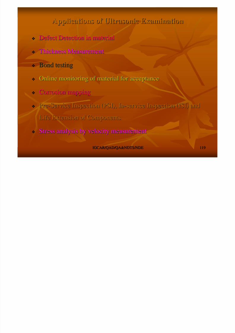
8/4/2019 Non-Destructive Examination 2
http://slidepdf.com/reader/full/non-destructive-examination-2 119/148
IGCAR/QAD/QA&NDTS/NDEIGCAR/QAD/QA&NDTS/NDE 119119
Thickness MeasurementThickness Measurement
Bond testingBond testing
Online monitoring of material for acceptanceOnline monitoring of material for acceptance
Corrosion mappingCorrosion mapping
PrePre--Service Inspection (PSI), InService Inspection (PSI), In--service Inspection (ISI) andservice Inspection (ISI) and
Life Extension of ComponentsLife Extension of Components
Stress analysis by velocity measurementStress analysis by velocity measurement
Advantages & Limitations of UEAdvantages & Limitations of UE
Single side accessibility is enoughSingle side accessibility is enough
Very good for planar defectsVery good for planar defects
Depth positioning is possibleDepth positioning is possible
Specimen shapeSpecimen shape –– odd &odd &irregular shape difficult toirregular shape difficult to
ii
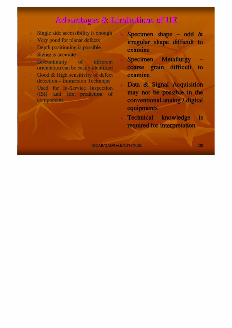
8/4/2019 Non-Destructive Examination 2
http://slidepdf.com/reader/full/non-destructive-examination-2 120/148
IGCAR/QAD/QA&NDTS/NDEIGCAR/QAD/QA&NDTS/NDE 120120
Depth positioning is possibleDepth positioning is possible
Sizing is accurateSizing is accurate
Discontinuity of differentDiscontinuity of differentorientation can be easily identifiedorientation can be easily identified
Good & High sensitivity of defectGood & High sensitivity of defectdetectiondetection –– Immersion TechniqueImmersion Technique
Used for InUsed for In--Service InspectionService Inspection
(ISI) and life prediction of (ISI) and life prediction of componentscomponents
examineexamine
Specimen MetallurgySpecimen Metallurgy ––
coarse grain difficult tocoarse grain difficult toexamineexamine
Data & Signal AcquisitionData & Signal Acquisition
may not be possible in themay not be possible in theconventional analog / digitalconventional analog / digital
equipmentsequipments
Technical knowledge isTechnical knowledge is
required for interpretationrequired for interpretation
8/4/2019 Non-Destructive Examination 2
http://slidepdf.com/reader/full/non-destructive-examination-2 121/148
On Line Studies of Fatigue Crack GrowthOn Line Studies of Fatigue Crack Growth
0
2
-30 -20 -10 0 10 20 30

8/4/2019 Non-Destructive Examination 2
http://slidepdf.com/reader/full/non-destructive-examination-2 122/148
IGCAR/QAD/QA&NDTS/NDEIGCAR/QAD/QA&NDTS/NDE 122122
4
6
8
10
12
14
16
Notch 10.115 10.125 10.135 10.145
10.155 10.165 10.175 10.195 10.205
10.210 10.215 10.2175 10.21788 10.220

8/4/2019 Non-Destructive Examination 2
http://slidepdf.com/reader/full/non-destructive-examination-2 123/148
IGCAR/QAD/QA&NDTS/NDEIGCAR/QAD/QA&NDTS/NDE 123123
LEAK TESTINGLEAK TESTING

8/4/2019 Non-Destructive Examination 2
http://slidepdf.com/reader/full/non-destructive-examination-2 124/148
LEAK TESTINGLEAK TESTING
LEAK TESTINGLEAK TESTING
FORM OF NDEFORM OF NDE
8/4/2019 Non-Destructive Examination 2
http://slidepdf.com/reader/full/non-destructive-examination-2 125/148
IGCAR/QAD/QA&NDTS/NDEIGCAR/QAD/QA&NDTS/NDE 125125
FORM OF NDEFORM OF NDE
DETECTION & LOCATION OF LEAKDETECTION & LOCATION OF LEAK
MEASUREMENT OF FLUID LEAKAGE IN EITHER PRESSURISEDMEASUREMENT OF FLUID LEAKAGE IN EITHER PRESSURISEDOR EVACUATAED COMP. / SYS.OR EVACUATAED COMP. / SYS.
LEAKLEAK
EXISTANCE OF PHYSICAL OPENINGEXISTANCE OF PHYSICAL OPENING
MAY BE CRACK, CREVICES, HOLE, FISSURES OR PASSAGEMAY BE CRACK, CREVICES, HOLE, FISSURES OR PASSAGE
WHICH ADMITS FLUIDS ESCAPEWHICH ADMITS FLUIDS ESCAPE
LEAKAGE ?LEAKAGE ?
SELECTION OF LEAK TESTINGSELECTION OF LEAK TESTING
MAINLY DEPENDS ON THE TYPE AND NATURE OFMAINLY DEPENDS ON THE TYPE AND NATURE OFCOMPONENTSCOMPONENTS

8/4/2019 Non-Destructive Examination 2
http://slidepdf.com/reader/full/non-destructive-examination-2 126/148
IGCAR/QAD/QA&NDTS/NDEIGCAR/QAD/QA&NDTS/NDE 126126
MORE STRINGENT WHEN HAZARDOUS FULIDS &MORE STRINGENT WHEN HAZARDOUS FULIDS &GASSES HANDLEDGASSES HANDLED
MASS SPECTROMETER HELIUM LEAK DETECTIONMASS SPECTROMETER HELIUM LEAK DETECTIONUNDER VACUUMUNDER VACUUM
PROVIDES ACCURATE LEAK RATEPROVIDES ACCURATE LEAK RATE
HIGHER SENSITIVITYHIGHER SENSITIVITY
SENSITIVITY UP TO 10SENSITIVITY UP TO 10 --1313 Pa.mPa.m33 / Sec. / Sec.
Tracer gas Pr Rise in Evacuated Sys
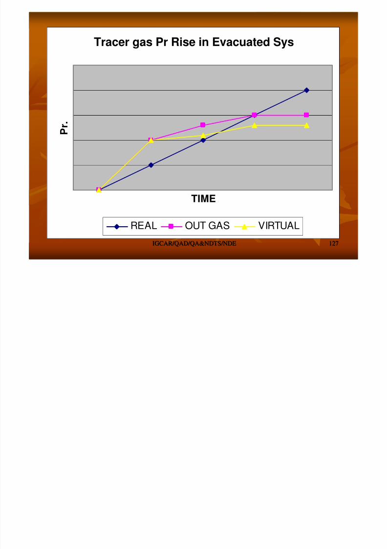
8/4/2019 Non-Destructive Examination 2
http://slidepdf.com/reader/full/non-destructive-examination-2 127/148
IGCAR/QAD/QA&NDTS/NDEIGCAR/QAD/QA&NDTS/NDE 127127
TIME
P r .
REAL OUT GAS VIRTUAL
SENSITIVITY OF VARIOUS METODSSENSITIVITY OF VARIOUS METODS
Generally limited to sizable leaks. Gives good overallGenerally limited to sizable leaks. Gives good overall
quantitative measure. No inf. On leak location & timequantitative measure. No inf. On leak location & time
Time LimitedTime LimitedMass LossMass Loss
(Pr. Change)(Pr. Change)
COMMENTSCOMMENTSMIN DETECTMIN DETECT --
ABLE LEAKABLE LEAK
RATERATE
(Pa m(Pa m33
/Sec) /Sec)
METHODMETHOD

8/4/2019 Non-Destructive Examination 2
http://slidepdf.com/reader/full/non-destructive-examination-2 128/148
IGCAR/QAD/QA&NDTS/NDEIGCAR/QAD/QA&NDTS/NDE 128128
Most sensitive for vacuum testing. Expensive. RelativelyMost sensitive for vacuum testing. Expensive. Relatively
complex. Not portable as that of Halogen Detectors. Muchcomplex. Not portable as that of Halogen Detectors. Much
less sensitive when used with pressure testing.less sensitive when used with pressure testing.
1010 --1212MassMass
SpectrometerSpectrometer
Operates in Air. Sensitive with SF6 (Operates in Air. Sensitive with SF6 (--12). Portable, requires12). Portable, requires
cleaning, losses with use, sensitive to ambient, halide gassescleaning, losses with use, sensitive to ambient, halide gasses
1010 --1010HalogenHalogen
Simple, compact, portable, inexpensive, sensitive to a numberSimple, compact, portable, inexpensive, sensitive to a number
of different gasses, operates in airof different gasses, operates in air
1010 --66ThermalThermal
ConductivityConductivity
Leak location. Fluids may plug small leaks. Requires cleaningLeak location. Fluids may plug small leaks. Requires cleaning1010 --55BubbleBubble
Simple to use. Location only. May plug small leaks. RequiresSimple to use. Location only. May plug small leaks. Requires
cleaning.cleaning.
1010 --44ChemicalChemical
PenetrantsPenetrants
Leak location only. Fast. No clean up. Can detect fromLeak location only. Fast. No clean up. Can detect from
distance. Useful for large leaksdistance. Useful for large leaks
0.050.05UltrasonicUltrasonic
consumingconsuming( g )( g )
PRESSURE CHANGE TESTPRESSURE CHANGE TEST
CAN ALSO BE TERMED ASCAN ALSO BE TERMED AS
PRESSURE HOLD, PRESSURE DECAY, PR. DROP / LOSSPRESSURE HOLD, PRESSURE DECAY, PR. DROP / LOSS
PRESSURE RISE, PRESSURE GAINPRESSURE RISE, PRESSURE GAIN
8/4/2019 Non-Destructive Examination 2
http://slidepdf.com/reader/full/non-destructive-examination-2 129/148
IGCAR/QAD/QA&NDTS/NDEIGCAR/QAD/QA&NDTS/NDE 129129
TECHNIQUESTECHNIQUES
PRESSURISED SYSTEMPRESSURISED SYSTEM EVACUATED SYSTEMEVACUATED SYSTEM
FLOW MEASUREMENT METHODFLOW MEASUREMENT METHOD
ADVANTAGESADVANTAGES
NO SPL. TACER REQUIREDNO SPL. TACER REQUIRED
PR. / VAC. GAUGES ALREADY INSTALLED CAN BE USEDPR. / VAC. GAUGES ALREADY INSTALLED CAN BE USED
LIMITATIONSLIMITATIONS
LONGER TIME REQD.LONGER TIME REQD. NO PRECISE LEAK LOCATIONNO PRECISE LEAK LOCATION
PR. CHANGE TECH. OF LEAK TESTINGPR. CHANGE TECH. OF LEAK TESTING
BARAMETRIC OR ATM. PR.BARAMETRIC OR ATM. PR.
PR. CAUSED BY EARTHPR. CAUSED BY EARTH’’S ATM.S ATM.
DECREASE WITH INCREASED ALTITUDEDECREASE WITH INCREASED ALTITUDE

8/4/2019 Non-Destructive Examination 2
http://slidepdf.com/reader/full/non-destructive-examination-2 130/148
IGCAR/QAD/QA&NDTS/NDEIGCAR/QAD/QA&NDTS/NDE 130130
STD. BAROMETRIC PR. AT SEA LEVEL = 101.325STD. BAROMETRIC PR. AT SEA LEVEL = 101.325
k.Pak.Pa GAUGE PRESSUREGAUGE PRESSURE
PRESSURE ABOVE ATM. PRESSUREPRESSURE ABOVE ATM. PRESSURE
UNITSUNITS –– k.Pa (GAUGE)k.Pa (GAUGE) ABSOLUTE PRESSUREABSOLUTE PRESSURE
PR. ABOVE ABS. ZERO VALUE CORRESPONDINGPR. ABOVE ABS. ZERO VALUE CORRESPONDINGTO EMPTY SPACETO EMPTY SPACE
EQUAL TO SUM OF LOCAL ATM. PR. & GAUGE PR.EQUAL TO SUM OF LOCAL ATM. PR. & GAUGE PR.
UNITUNIT –– k.Pa.k.Pa.
PR. CHANGE RATESPR. CHANGE RATES
CONST. TEMP. WITH PR. CHANGECONST. TEMP. WITH PR. CHANGE
dP/dTdP/dT = (P1= (P1 –– P2) / P2) / dTdT
CONST. VOL. WITH PR. CHANGECONST. VOL. WITH PR. CHANGE
P1 / P2 = T1 / T2 or P1 = (T1 / T2) x P2P1 / P2 = T1 / T2 or P1 = (T1 / T2) x P2
TEMP CORRECTIONTEMP CORRECTION

8/4/2019 Non-Destructive Examination 2
http://slidepdf.com/reader/full/non-destructive-examination-2 131/148
IGCAR/QAD/QA&NDTS/NDEIGCAR/QAD/QA&NDTS/NDE 131131
TEMP. CORRECTIONTEMP. CORRECTION
dP/dTdP/dT= [(P1+101) (T1+273) / T2 + 273)] / = [(P1+101) (T1+273) / T2 + 273)] / dTdT (SI Units(SI Units –– kPa, C)kPa, C)
dPdP / / dTdT = [P1= [P1 –– P2 (T1 / T2)] / P2 (T1 / T2)] / dTdT (For all abs. units)(For all abs. units)
TYPESTYPES
PR. CHANGE TESTS FOR PRESSURISED SYSTEMPR. CHANGE TESTS FOR PRESSURISED SYSTEM
PR. CHANGE TESTS FOR EVACUATED SYSTEMPR. CHANGE TESTS FOR EVACUATED SYSTEM
VAC. UNITS:VAC. UNITS: 1 TORR = 133 Pa; 760 TORR = 101.325 k.Pa1 TORR = 133 Pa; 760 TORR = 101.325 k.Pa OUTGASSINGOUTGASSING
PUMPDOWN TIMEPUMPDOWN TIME T = 2.3 V /S {T in Sec, vT = 2.3 V /S {T in Sec, v-- VolVol in Cu.m, Sin Cu.m, S –– PumpingPumpingSpeed in Cu.m/Sec}Speed in Cu.m/Sec}
LEAKAGE RATELEAKAGE RATE Q = (P2Q = (P2 –– P1) V / t (SI Units)P1) V / t (SI Units)
BUBBLE LEAK TESTINGBUBBLE LEAK TESTING
PRESSURE DIFFERENCE ESTABLISHEDPRESSURE DIFFERENCE ESTABLISHED
LIQUID IS PLACED IN CONTACT AT LOWERLIQUID IS PLACED IN CONTACT AT LOWER

8/4/2019 Non-Destructive Examination 2
http://slidepdf.com/reader/full/non-destructive-examination-2 132/148
IGCAR/QAD/QA&NDTS/NDEIGCAR/QAD/QA&NDTS/NDE 132132
LIQUID IS PLACED IN CONTACT AT LOWERLIQUID IS PLACED IN CONTACT AT LOWER
PRESSURE SIDEPRESSURE SIDE
BUBBLE FORMATION ON THE EXIT SIDEBUBBLE FORMATION ON THE EXIT SIDE
CLASSIFICATIONCLASSIFICATION
LIQUID FILM APPLICATIONLIQUID FILM APPLICATION
LIQUID IMMERSION TECHNIQUELIQUID IMMERSION TECHNIQUE
FOAM APPLICATIONFOAM APPLICATION
TRACER GASESTRACER GASES
AIR, AMMONIA, NITROGENAIR, AMMONIA, NITROGEN
HELIUMHELIUM –– MOST SUITABLE FOR LOW LEAKAGESMOST SUITABLE FOR LOW LEAKAGES

8/4/2019 Non-Destructive Examination 2
http://slidepdf.com/reader/full/non-destructive-examination-2 133/148
IGCAR/QAD/QA&NDTS/NDEIGCAR/QAD/QA&NDTS/NDE 133133
HELIUM MOST SUITABLE FOR LOW LEAKAGES
LIQUID FILM APPLN.LIQUID FILM APPLN.
SOAP SOL: 1 PART LIQ DETERGENT + 1 PART GLYCERINE +SOAP SOL: 1 PART LIQ DETERGENT + 1 PART GLYCERINE +
4.5 PARTS WATER4.5 PARTS WATER
ALCOHOL + ETHYLENE ADDED FOR ANTI FREEZEALCOHOL + ETHYLENE ADDED FOR ANTI FREEZE
SENSITIVITYSENSITIVITY 1010 --3 Std. CC / Sec3 Std. CC / Sec –– SHOP / FIELD CONDN.SHOP / FIELD CONDN.
1010 --5 Std. CC / Sec5 Std. CC / Sec –– LAB CONDN.LAB CONDN.
PREPARATION OF SPCIMEN / PREPARATION OF SPCIMEN /
COMPONENTCOMPONENT
CLEANINGCLEANING –– FREE FROM OIL, GREASE, PAINTFREE FROM OIL, GREASE, PAINT SEALING OF OPENINGSSEALING OF OPENINGS

8/4/2019 Non-Destructive Examination 2
http://slidepdf.com/reader/full/non-destructive-examination-2 134/148
IGCAR/QAD/QA&NDTS/NDEIGCAR/QAD/QA&NDTS/NDE 134134
SOAK TIMESOAK TIME –– REC. 15 MinREC. 15 Min
SPECIAL TECH.SPECIAL TECH.
HEATING OF SEALED COMP., APPLY SOLN.HEATING OF SEALED COMP., APPLY SOLN.
PARTIAL VAC. CREATION ON TEST LIQ.PARTIAL VAC. CREATION ON TEST LIQ.
CRYOGENIC IMMERSION & TESTING AT AMB. TEM. SOL.CRYOGENIC IMMERSION & TESTING AT AMB. TEM. SOL.
VACUUM TECH. FOR BUBBLE TESTINGVACUUM TECH. FOR BUBBLE TESTING
VAC. CHAMBER SUITABLE FOR COMP.VAC. CHAMBER SUITABLE FOR COMP.
VAC. BOX METHOD FOR LARGE & ODD COMP.VAC. BOX METHOD FOR LARGE & ODD COMP.
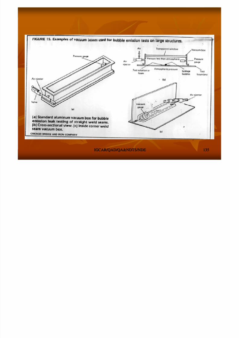
8/4/2019 Non-Destructive Examination 2
http://slidepdf.com/reader/full/non-destructive-examination-2 135/148
IGCAR/QAD/QA&NDTS/NDEIGCAR/QAD/QA&NDTS/NDE 135135
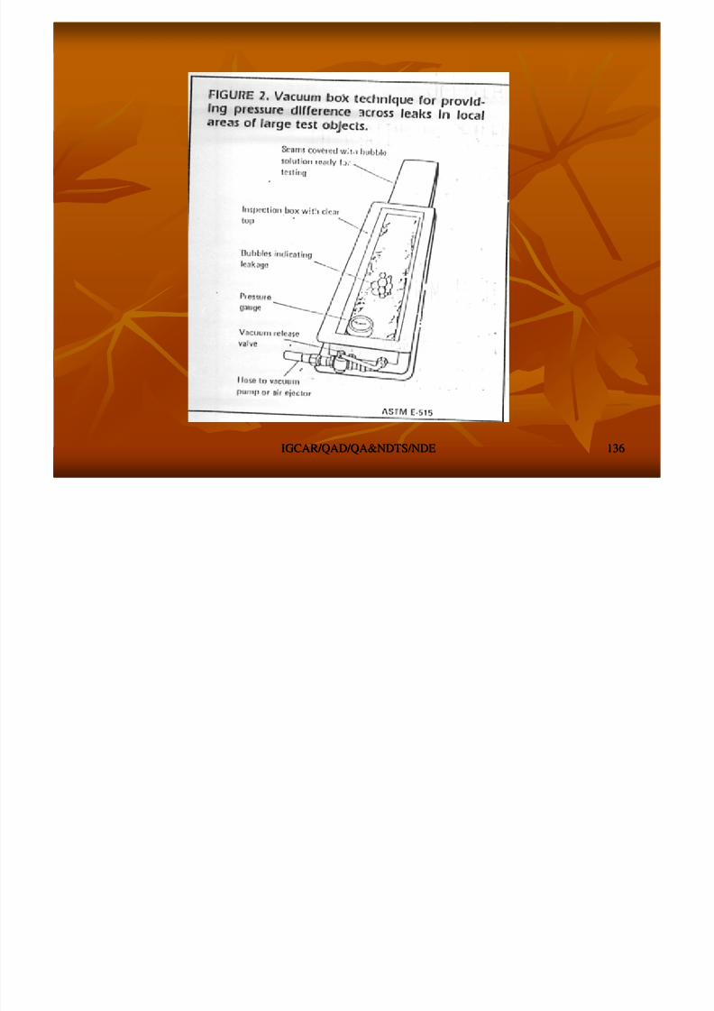
8/4/2019 Non-Destructive Examination 2
http://slidepdf.com/reader/full/non-destructive-examination-2 136/148
IGCAR/QAD/QA&NDTS/NDEIGCAR/QAD/QA&NDTS/NDE 136136
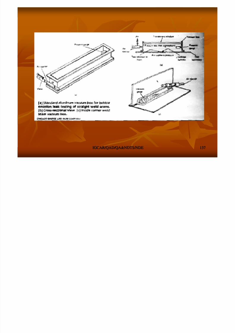
8/4/2019 Non-Destructive Examination 2
http://slidepdf.com/reader/full/non-destructive-examination-2 137/148
IGCAR/QAD/QA&NDTS/NDEIGCAR/QAD/QA&NDTS/NDE 137137
HALOGEN LEAK TESTINGHALOGEN LEAK TESTING
RESPONDS TO MOST GASEOUS COMPOUNDS THATRESPONDS TO MOST GASEOUS COMPOUNDS THATCONTAINS HALOGENCONTAINS HALOGEN
HALOGENSHALOGENS –– ClCl F Br IF Br I
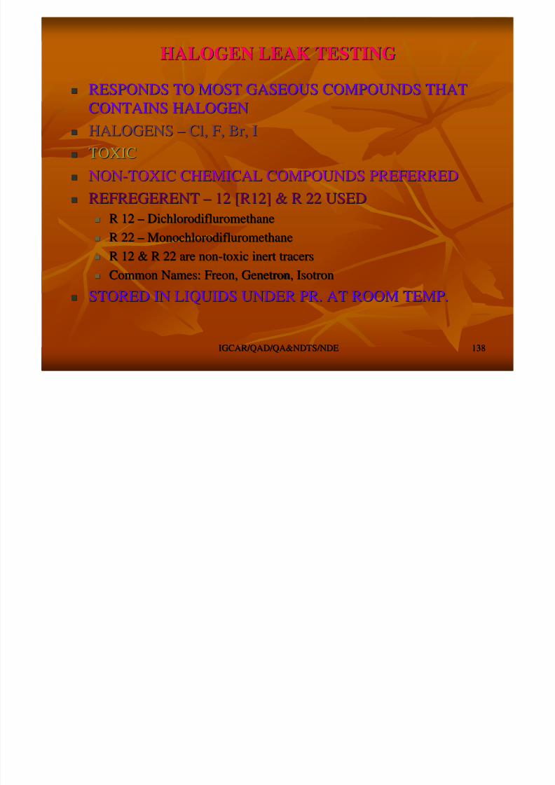
8/4/2019 Non-Destructive Examination 2
http://slidepdf.com/reader/full/non-destructive-examination-2 138/148
IGCAR/QAD/QA&NDTS/NDEIGCAR/QAD/QA&NDTS/NDE 138138
HALOGENSHALOGENS ClCl, F, Br, I, F, Br, I
TOXICTOXIC NONNON--TOXIC CHEMICAL COMPOUNDS PREFERREDTOXIC CHEMICAL COMPOUNDS PREFERRED
REFREGERENTREFREGERENT –– 12 [R12] & R 22 USED12 [R12] & R 22 USED
R 12R 12 –– DichlorodifluromethaneDichlorodifluromethane
R 22R 22 –– MonochlorodifluromethaneMonochlorodifluromethane
R 12 & R 22 are nonR 12 & R 22 are non--toxic inert tracerstoxic inert tracers
Common Names: Freon,Common Names: Freon, GenetronGenetron,, IsotronIsotron
STORED IN LIQUIDS UNDER PR. AT ROOM TEMP.STORED IN LIQUIDS UNDER PR. AT ROOM TEMP.
GAS PROPERTIESGAS PROPERTIES
86.486.4120.9120.9Molecular WtMolecular Wt
CHClFCHClF22CClCCl22FF22Chemical FormulaChemical Formula
R 22R 22R 12R 12PropertiesProperties
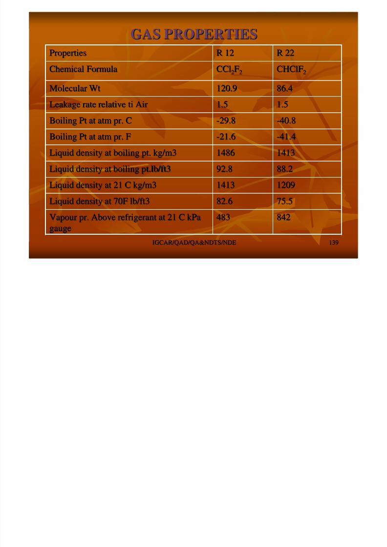
8/4/2019 Non-Destructive Examination 2
http://slidepdf.com/reader/full/non-destructive-examination-2 139/148
IGCAR/QAD/QA&NDTS/NDEIGCAR/QAD/QA&NDTS/NDE 139139
842842483483Vapour pr. Above refrigerant at 21 C kPaVapour pr. Above refrigerant at 21 C kPa
gaugegauge
75.575.582.682.6Liquid density at 70F lb/ft3Liquid density at 70F lb/ft3
1209120914131413Liquid density at 21 C kg/m3Liquid density at 21 C kg/m3
88.288.292.892.8Liquid density at boiling pt.lb/ft3Liquid density at boiling pt.lb/ft3
1413141314861486Liquid density at boiling pt. kg/m3Liquid density at boiling pt. kg/m3
--41.441.4--21.621.6Boiling Pt at atm pr. FBoiling Pt at atm pr. F
--40.840.8--29.829.8Boiling Pt at atm pr. CBoiling Pt at atm pr. C
1.51.51.51.5Leakage rate relativeLeakage rate relative titi AirAir
TYPES OF DETECTORSTYPES OF DETECTORS
HALIDE TORCHHALIDE TORCH
HEATED ANODE HALOGEN DETECTORHEATED ANODE HALOGEN DETECTOR

8/4/2019 Non-Destructive Examination 2
http://slidepdf.com/reader/full/non-destructive-examination-2 140/148
IGCAR/QAD/QA&NDTS/NDEIGCAR/QAD/QA&NDTS/NDE 140140
ELECTRON CAPTURE DETECTORELECTRON CAPTURE DETECTOR
HALIDE TORCH DETECTORHALIDE TORCH DETECTOR
NORMAL FLAMENORMAL FLAME
––
PALE BLUE WITH AIR ALONEPALE BLUE WITH AIR ALONE
GREEN WITH PRESENCE OF HALIDEGREEN WITH PRESENCE OF HALIDE
SENSITIVITYSENSITIVITY –– 1010 --44 Std. CC / Sec.Std. CC / Sec.
FOR LOCATION OF LEAKS ON PRESSURISEDFOR LOCATION OF LEAKS ON PRESSURISED
SYSTEMSYSTEM SCAN ALWAYS FROM TOPSCAN ALWAYS FROM TOP
TYPES OF DETECTORSTYPES OF DETECTORS
RED HOT PLATINUM, AND CERAMIC HEATERRED HOT PLATINUM, AND CERAMIC HEATERELEMENTS ASSY EMITS +VE IONSELEMENTS ASSY EMITS +VE IONS
CYLINDRICAL CATHODS COLLECTD IONSCYLINDRICAL CATHODS COLLECTD IONS
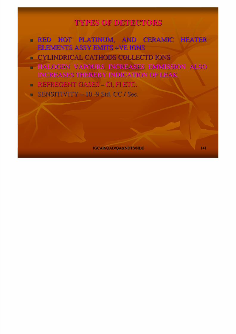
8/4/2019 Non-Destructive Examination 2
http://slidepdf.com/reader/full/non-destructive-examination-2 141/148
IGCAR/QAD/QA&NDTS/NDEIGCAR/QAD/QA&NDTS/NDE 141141
CYLINDRICAL CATHODS COLLECTD IONSCYLINDRICAL CATHODS COLLECTD IONS
HALOGEN VAPOURS INCREASES EMMISSION ALSOHALOGEN VAPOURS INCREASES EMMISSION ALSOINCREASES THEREBY INDICATION OF LEAKINCREASES THEREBY INDICATION OF LEAK
REFREGENT GASESREFREGENT GASES –– ClCl, Fl ETC., Fl ETC.
SENSITIVITYSENSITIVITY –– 1010 --9 Std. CC / Sec.9 Std. CC / Sec.
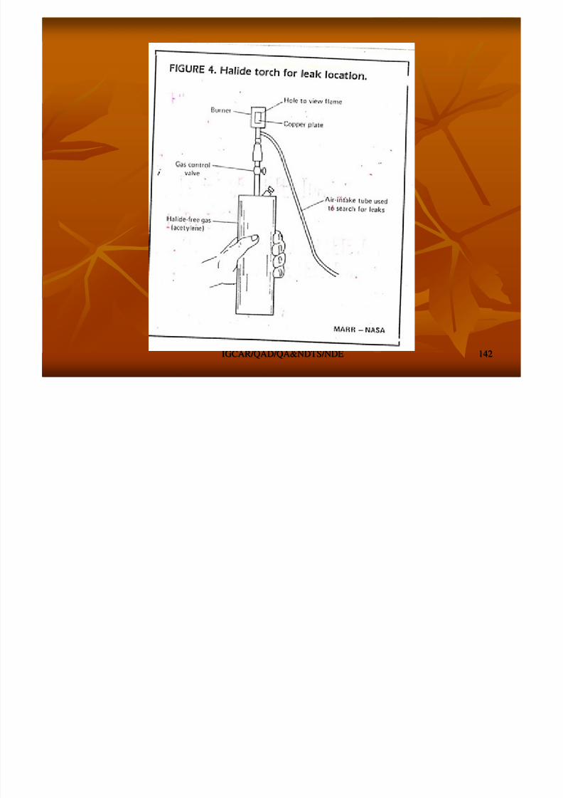
8/4/2019 Non-Destructive Examination 2
http://slidepdf.com/reader/full/non-destructive-examination-2 142/148
IGCAR/QAD/QA&NDTS/NDEIGCAR/QAD/QA&NDTS/NDE 142142
MASS SPECTROMETER LEAK DETECTORMASS SPECTROMETER LEAK DETECTOR
MOST SENSITIVE & ACCURATEMOST SENSITIVE & ACCURATE
PORTABLEPORTABLE
SUITABLE FOR ALL TYPES OF COMPONENTSSUITABLE FOR ALL TYPES OF COMPONENTS
MSLD CONSISTSMSLD CONSISTS

8/4/2019 Non-Destructive Examination 2
http://slidepdf.com/reader/full/non-destructive-examination-2 143/148
IGCAR/QAD/QA&NDTS/NDEIGCAR/QAD/QA&NDTS/NDE 143143
MASS SPECTROMETERMASS SPECTROMETER
HIGH VACUUM SYSTEMHIGH VACUUM SYSTEM
ELECTRONIC CONTROLSELECTRONIC CONTROLS
PORTS FOR STD. LEAK & COMPONENTSPORTS FOR STD. LEAK & COMPONENTS
LEAK TESTING METHODSLEAK TESTING METHODS
VACUUM LEAK TESTINGVACUUM LEAK TESTING
PRESSURE LEAK TESTINGPRESSURE LEAK TESTING
PRESSUREPRESSURE –– VACUUM COMBINATIONVACUUM COMBINATION
NDE in Various LevelsNDE in Various Levels
NDE is used in design to understand the effect of discontinuityNDE is used in design to understand the effect of discontinuity
during operation / service conditionduring operation / service condition
8/4/2019 Non-Destructive Examination 2
http://slidepdf.com/reader/full/non-destructive-examination-2 144/148
IGCAR/QAD/QA&NDTS/NDEIGCAR/QAD/QA&NDTS/NDE 144144
The discontinuity type, size and orientation is very muchThe discontinuity type, size and orientation is very much
important for design considerationimportant for design consideration
NDE used in preNDE used in pre--service and inservice and in--service inspection to assessservice inspection to assess
the integrity of the components / system during commissioningthe integrity of the components / system during commissioning
and serviceand service
NDE is used for Component / System life prediction and lifeNDE is used for Component / System life prediction and life
extensionextension
APPLIED STRESS YIELD TENSILE STRENGTH
(a) The Strength of materials approach
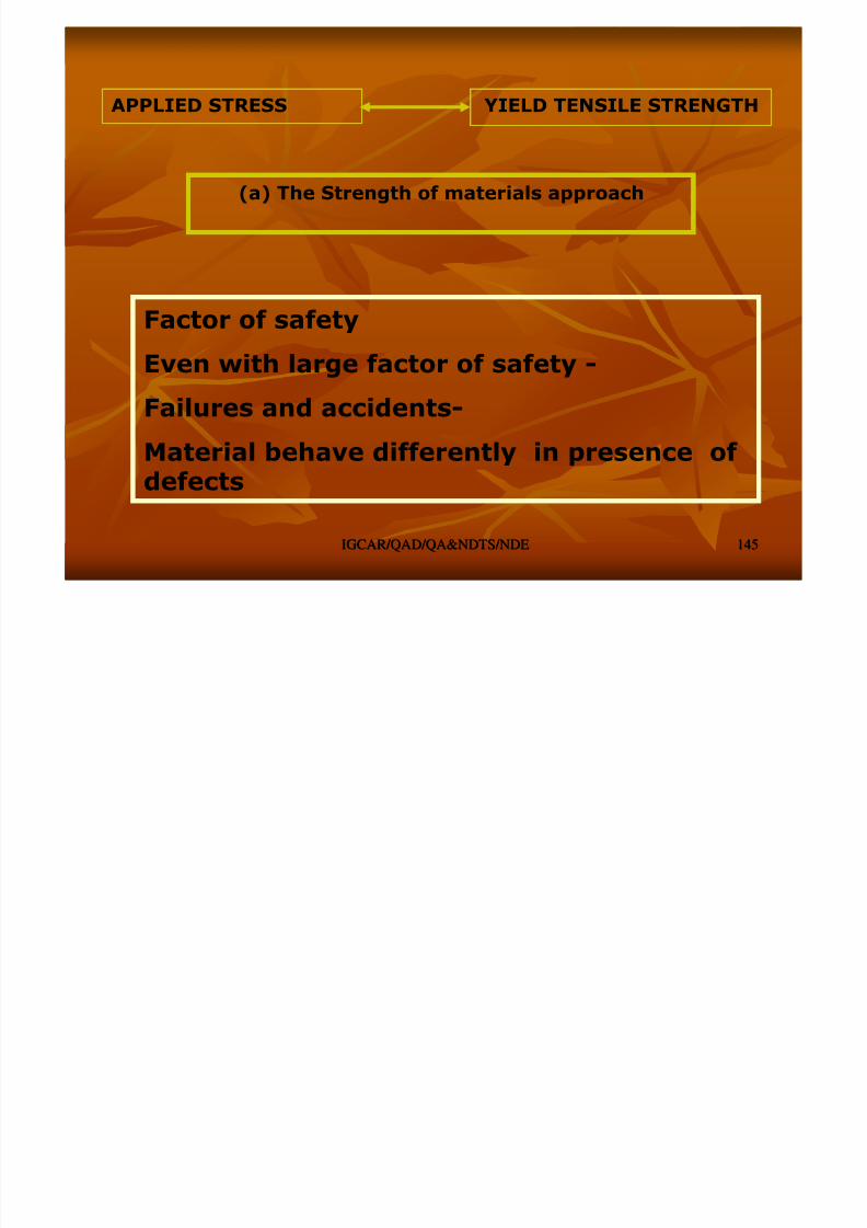
8/4/2019 Non-Destructive Examination 2
http://slidepdf.com/reader/full/non-destructive-examination-2 145/148
IGCAR/QAD/QA&NDTS/NDEIGCAR/QAD/QA&NDTS/NDE 145145
Factor of safety
Even with large factor of safety -
Failures and accidents-
Material behave differently in presence of defects
NDT & Fracture MechanicsNDT & Fracture Mechanics
Fracture mechanics approach – damage tolerance approach(propagates the idea of “live with discontinuities”)
A material property, fracture toughness (KIc) is defined and thischaracterizes the material behaviour in presence of discontinuities
which the earlier strength of materials design approach has nottaken into account K can be experimentally determined
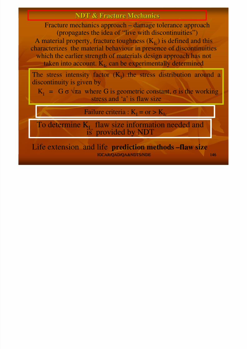
8/4/2019 Non-Destructive Examination 2
http://slidepdf.com/reader/full/non-destructive-examination-2 146/148
IGCAR/QAD/QA&NDTS/NDEIGCAR/QAD/QA&NDTS/NDE 146146
taken into account. KIc can be experimentally determined
The stress intensity factor (KI) the stress distribution around adiscontinuity is given by
KI = G σ √πa where G is geometric constant, σ is the working
stress and ‘a’ is flaw sizeFailure criteria : KI = or > KIc
To determine KI,, flaw size information needed and
is provided by NDT
Life extension and life prediction methods –flaw size
APPLIED STRESS YIELD TENSILE STRENGTH
(a) The Strength of materials approach
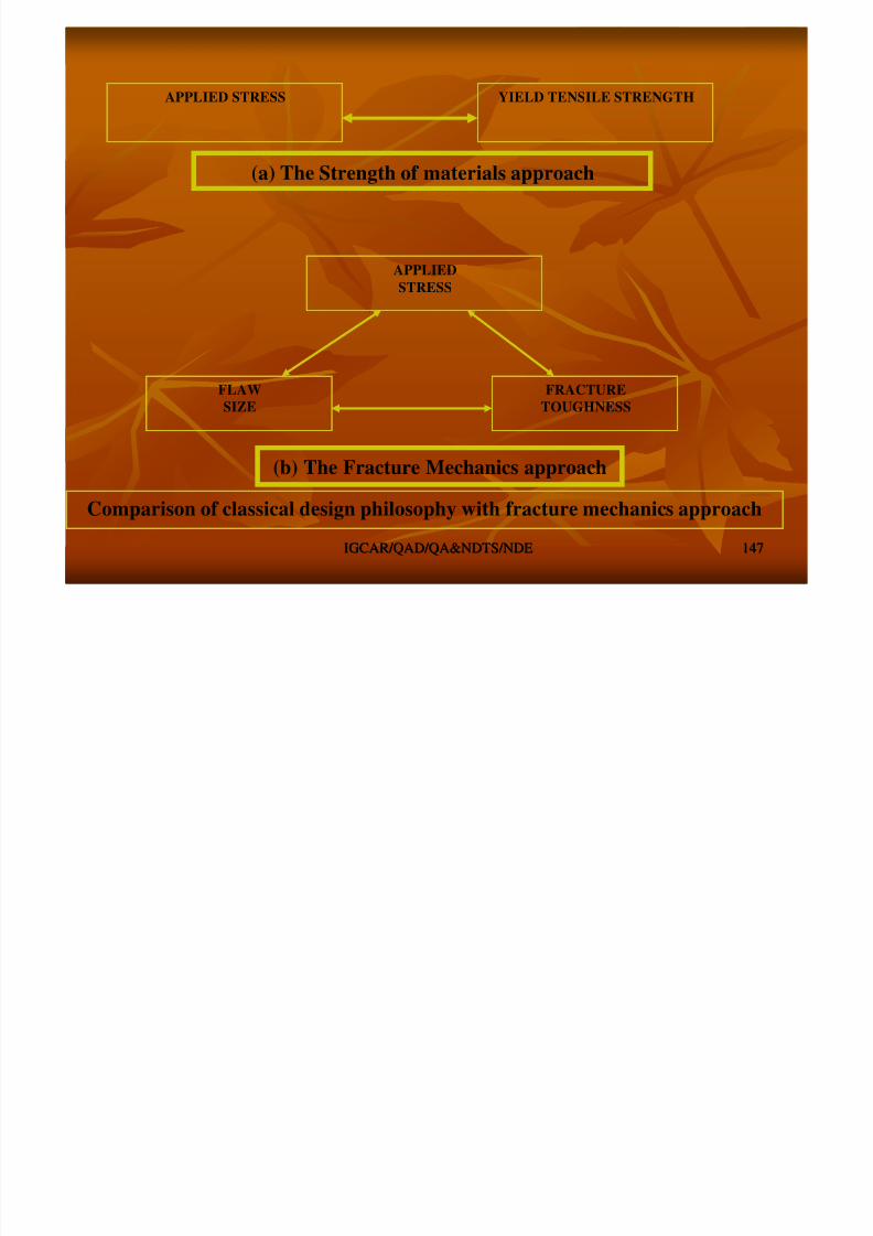
8/4/2019 Non-Destructive Examination 2
http://slidepdf.com/reader/full/non-destructive-examination-2 147/148
IGCAR/QAD/QA&NDTS/NDEIGCAR/QAD/QA&NDTS/NDE 147147
APPLIED
STRESS
FLAW
SIZE
FRACTURE
TOUGHNESS
(b) The Fracture Mechanics approach
Comparison of classical design philosophy with fracture mechanics approach
NDE is used to inspect pipelines
to prevent leaks that coulddamage the environment. Visualinspection, radiography andelectromagnetic testing are someof the NDE methods used.
NDENDE
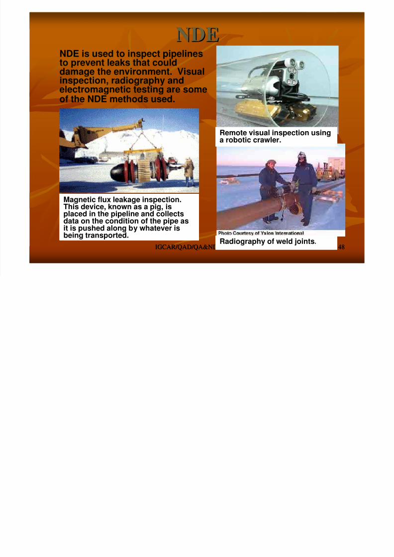
8/4/2019 Non-Destructive Examination 2
http://slidepdf.com/reader/full/non-destructive-examination-2 148/148
IGCAR/QAD/QA&NDTS/NDEIGCAR/QAD/QA&NDTS/NDE 148148
of the NDE methods used.
Remote visual inspection usinga robotic crawler.
Radiography of weld joints.
Magnetic flux leakage inspection.This device, known as a pig, isplaced in the pipeline and collectsdata on the condition of the pipe asit is pushed along by whatever isbeing transported.