nes 729 part 5 requirements for non-destructive examination methods
DESCRIPTION
Requirements for Non-Destructive Examination MethodsTRANSCRIPT

Ministry of Defence Defence Standard 02-729 (NES 729)
Issue 1 Publication Date 01 April 2000
Incorporating NES 729 Category 2
Issue 1 Publication Date November 1984
Requirements For Non-DestructiveExamination Methods
Part 5Ultrasonic
AMENDMENT RECORD
Amd No Date Text Affected Signature and Date
REVISION NOTE
This standard is raised to Issue 1 to update its content.
HISTORICAL RECORD
This standard supersedes the following:
Naval Engineering Standard (NES) 729 Part 5 Issue 1 dated November 1984.
Ministry of Defence
Naval Engineering Standard
NES 729 Part 5 Issue 1 (Reformatted) November 1984
REQUIREMENTS FORNON-DESTRUCTIVE EXAMINATION METHODS
PART 5
ULTRASONIC
This NES Supersedes
DGS/PS/9022 PART 6
Record of Amendments
AMDT INSERTED BY DATE
1
2
3
4
5
6
7
8
9
10
i
NAVAL ENGINEERING STANDARD 729
REQUIREMENTS FOR NON-DESTRICTIVE EXAMINATION METHODS
PART 5
ISSUE 1 (REFORMATTED)
ULTRASONIC
The issue and use of this Standard
is authorized for use in MOD contracts
by MOD(PE) Sea Systems and
the Naval Support Command
ECROWN COPYRIGHT
Published by:
Director of Naval ArchitectureProcurement Executive, Ministry of DefenceSea Systems, Foxhill, Bath BA1 5AB

ii
NES 729Part 5
Issue 1 (Reformatted)
iii
SCOPE
1. This NES covers the procedures and methods to be used for the Quality Assessment ofUltrasonic Examining Authorities and for production ultrasonic examination. The methodsdescribed are the minimum requirements for the detection of surface and sub-surfaceimperfections in welded and brazed joints, cast and wrought materials and for themeasurement of plate and tube wall thickness, but does not contain acceptance criteria fordefects thus revealed. Manual methods only are covered but automatic and mechanicallyassisted methods and associated recording systems are to be applied whenever the extent ofthe examination justifies the need to minimize operator induced variables and the equipmentcost.
2. The effective application of ultrasonic examination may be restricted in materials withinherently high or variable attenuation or which produce severe scattering of the ultrasonicbeam. Complex shapes may also limit satisfactory application and the examination is to beapplied at stages duringmanufacture when the geometry of the component is relatively simpleprovided that subsequent specified treatments of the material do not render the examinationineffective.
3. The extent to which ultrasonic examination is required is not included herein. This will bestated in the Contract Documents.
4. This NES does not apply to nuclear plant and machinery to which DG Ships/PS/5108 applies.

NES 729Part 5Issue 1 (Reformatted)
iv

NES 729Part 5
Issue 1 (Reformatted)
v
FOREWORD
Sponsorship
1. ThisNaval Engineering Standard (NES) is sponsored by theProcurement Executive, Ministryof Defence (MOD(PE)), Deputy Controller Warships (DCW), Section NA 133.
2. It is to be applied as required by any MOD(PE) contract for the non-destructive examinationof metals and is applicable to Surface Ships and Submarines.
3. This NES comprises:
Requirements for Non-destructive Examination Methods
Part 1 Radiographic
Part 2 Magnetic Particle
Part 3 Eddy Current
Part 4 Liquid Penetrant
Part 5 Ultrasonic
4. If it is found to be technically unsuitable for any particular requirement the sponsor is to beinformed in writing of the circumstances with a copy to Deputy Controller WarshipEquipment (DCWE), Section TE 112a.
5. Any user of this NES either within MOD or in outside industry may propose an amendmentto it. Proposals for amendments which are:
a. not directly applicable to a particular contract are to be made to the sponsor of the NES.
b. directly applicable to a particular contract are to be dealt with using existingdepartmental procedures or as specified in the contract.
6. No alteration is to be made to this NES except by the issue of a formal amendment.
7. Unless otherwise stated, reference in this NES to approval, approved, authorized or similarterms means by the Procurement Executive, Ministry of Defence.
8. Any significant amendments that may be made to this NES at a later date will be indicatedby a vertical side line. Deletions will be indicated by 000 appearing at the end of the lineintervals.
Conditions of Release
General
9. This Naval Engineering Standard (NES) has been prepared for the use of the Crown and ofits contractors in the execution of contracts for the Crown. The Crown hereby excludes allliability (other than liability for death or personal injury) whatsoever and howsoever arising(including but without limitation, negligence on the part of the Crown, its servants or agents)for any loss or damage however caused where the NES is used for any other purpose.
10. This document is Crown Copyright and the information herein may be subject to Crown orthird party rights. It is not to be released, reproduced or published without written permissionof the MOD.
11. The Crown reserves the right to amend or modify the contents of this NES without consultingor informing any holder.

NES 729Part 5Issue 1 (Reformatted)
vi
MOD Tender or Contract Process
12. ThisNES is the property of the Crown and unless otherwise authorized in writing by theMODmust be returned on completion of the contract, or submission of the tender, in connectionwith which it is issued.
13. When this NES is used in connection with aMOD tender or contract, the user is to ensure thathe is in possession of the appropriate version of each document, including related documents,relevant to each particular tender or contract. Enquiries in this connection may be made ofthe local MOD(PE) Quality Assurance Representative or the Authority named in the tenderor contract.
14. When NES are incorporated into MOD contracts, users are responsible for their correctapplication and for complying with contracts and any other statutory requirements.Compliance with an NES does not of itself confer immunity from legal obligations.
Related Documents
15. In the tender and procurement processes the related documents listed in each section andAnnex A can be obtained as follows:
a. British Standards British Standards Institution,389 Chiswick High Road,London W4 4AL
b. Defence Standards Directorate of Standardization and Safety Policy,Stan 1, Kentigern House, 65 Brown Street,Glasgow G2 8EX
c. Naval Engineering Standards CSE3a, CSE Llangennech, Llanelli,Dyfed SA14 8YP
d. Other documents Tender or Contract Sponsor to advise.
Note: Tender or Contract Sponsor can advise in cases of difficulty.
16. All applications to Ministry Establishments for related documents are to quote the relevantMOD Invitation to Tender or Contract Number and date, together with the sponsoringDirectorate and the Tender or Contract Sponsor.
17. Prime Contractors are responsible for supplying their subcontractors with relevantdocumentation, including specifications, standards and drawings.
Health and Safety
Warning
18. ThisNESmay call for the use of processes, substances and/or procedures thatmay be injuriousto health if adequate precautions are not taken. It refers only to technical suitability and inno way absolves either the supplier or the user from statutory obligations relating to healthand safety at any stage of manufacture or use. Where attention is drawn to hazards, thosequoted may not necessarily be exhaustive.
NES 729Part 5
Issue 1 (Reformatted)
vii
CONTENTSPage No
TITLE PAGE i. . . . . . . . . . . . . . . . . . . . . . . . . . . . . . . . . . . . . . . . . . . . . . . . . . . . . . .
SCOPE iii. . . . . . . . . . . . . . . . . . . . . . . . . . . . . . . . . . . . . . . . . . . . . . . . . . . . . . . . . . . .
FOREWORD v. . . . . . . . . . . . . . . . . . . . . . . . . . . . . . . . . . . . . . . . . . . . . . . . . . . . . . .Sponsorship v. . . . . . . . . . . . . . . . . . . . . . . . . . . . . . . . . . . . . . . . . . . . . . . . . . .Conditions of Release v. . . . . . . . . . . . . . . . . . . . . . . . . . . . . . . . . . . . . . . . . . .
General v. . . . . . . . . . . . . . . . . . . . . . . . . . . . . . . . . . . . . . . . . . . . . . . .MOD Tender or Contract Process vi. . . . . . . . . . . . . . . . . . . . . . . . . .
Related Documents vi. . . . . . . . . . . . . . . . . . . . . . . . . . . . . . . . . . . . . . . . . . . .Health and Safety vi. . . . . . . . . . . . . . . . . . . . . . . . . . . . . . . . . . . . . . . . . . . . . .
Warning vi. . . . . . . . . . . . . . . . . . . . . . . . . . . . . . . . . . . . . . . . . . . . . . . .
CONTENTS vii. . . . . . . . . . . . . . . . . . . . . . . . . . . . . . . . . . . . . . . . . . . . . . . . . . . . . . . .
SECTION 1. ACCEPTANCE STANDARDS 1.1. . . . . . . . . . . . . . . . .
SECTION 2. INSPECTION 2.1. . . . . . . . . . . . . . . . . . . . . . . . . . . . . . .
SECTION 3. GENERAL INSPECTION REQUIREMENTS 3.1. . . .3.1 Test Procedure 3.1. . . . . . . . . . . . . . . . . . . . . . . . . . . . . . .3.2 Personnel Requirements 3.1. . . . . . . . . . . . . . . . . . . . . .
FIGURE 3.1 SPECIMEN—ULTRASONICEXAMINATION PROCEDURE 3.2. . . . . . . . . . . . . . . .
3.3 Equipment Requirements 3.3. . . . . . . . . . . . . . . . . . . . .3.4 Equipment Performance Characteristics 3.3. . . . . . . . .3.5 Equipment Qualification 3.4. . . . . . . . . . . . . . . . . . . . . .3.6 Sensitivity Calibration Reference/Test Blocks 3.4. . . . .3.7 Method of Examination 3.5. . . . . . . . . . . . . . . . . . . . . . .3.8 Surface Finish 3.5. . . . . . . . . . . . . . . . . . . . . . . . . . . . . . .
SECTION 4. PLATE MATERIAL 4.1. . . . . . . . . . . . . . . . . . . . . . . . . .4.1 Application 4.1. . . . . . . . . . . . . . . . . . . . . . . . . . . . . . . . .4.2 Surface Preparation 4.1. . . . . . . . . . . . . . . . . . . . . . . . . .4.3 Compressional Wave Inspection 4.1. . . . . . . . . . . . . . . .4.4 Calibration 4.1. . . . . . . . . . . . . . . . . . . . . . . . . . . . . . . . .4.5 Method of Examination 4.2. . . . . . . . . . . . . . . . . . . . . . .4.6 Shear Wave Examination 4.2. . . . . . . . . . . . . . . . . . . . . .
TABLE 4.1 NOTCH DIMENSIONS 4.2. . . . . . . . . . . .4.7 Recording 4.3. . . . . . . . . . . . . . . . . . . . . . . . . . . . . . . . . .
SECTION 5. PLATE THICKNESS MEASUREMENT 5.1. . . . . . . .5.1 Instrument Calibration 5.1. . . . . . . . . . . . . . . . . . . . . . .5.2 Coverage 5.1. . . . . . . . . . . . . . . . . . . . . . . . . . . . . . . . . . .5.3 Surface Preparation 5.1. . . . . . . . . . . . . . . . . . . . . . . . . .
SECTION 6. BUTT WELDING 6.1. . . . . . . . . . . . . . . . . . . . . . . . . . . .6.1 Application 6.1. . . . . . . . . . . . . . . . . . . . . . . . . . . . . . . . .
NES 729Part 5Issue 1 (Reformatted)
viii
6.2 Probes 6.1. . . . . . . . . . . . . . . . . . . . . . . . . . . . . . . . . . . . . .TABLE 6.1 BEAM ANGLES 6.1. . . . . . . . . . . . . . . . . .TABLE 6.2 USE OF T-TYPE PROBES 6.1. . . . . . . . .
6.3 Surface Preparation 6.2. . . . . . . . . . . . . . . . . . . . . . . . . .6.4 Calibration 6.2. . . . . . . . . . . . . . . . . . . . . . . . . . . . . . . . .6.5 Method of Examination 6.2. . . . . . . . . . . . . . . . . . . . . . .6.6 Records 6.3. . . . . . . . . . . . . . . . . . . . . . . . . . . . . . . . . . . .
FIGURE 6.1 REFERENCE/TEST BLOCKSFOR WELD THICKNESS UP TO ANDINCLUDING 38mm 6.4. . . . . . . . . . . . . . . . . . . . . . . . . .FIGURE 6.2 REFERENCE/TEST BLOCKSFOR WELD THICKNESS GREATER THAN38mm 6.4. . . . . . . . . . . . . . . . . . . . . . . . . . . . . . . . . . . . . .FIGURE 6.4 REFERENCE/TEST BLOCK FORWELD STRADDLE SCANNING 6.6. . . . . . . . . . . . . . .FIGURE 6.5 REFERENCE/TEST BLOCKDIAGRAMMATIC SET-UP FOR STRADDLESCAN 6.6. . . . . . . . . . . . . . . . . . . . . . . . . . . . . . . . . . . . . .
SECTION 7. TEE-BUTT WELDING 7.1. . . . . . . . . . . . . . . . . . . . . . .7.1 Application 7.1. . . . . . . . . . . . . . . . . . . . . . . . . . . . . . . . .7.2 Surface Preparation 7.1. . . . . . . . . . . . . . . . . . . . . . . . . .7.3 Test Blocks 7.1. . . . . . . . . . . . . . . . . . . . . . . . . . . . . . . . . .
FIGURE 7.1 COMBINATION BLOCKCOVERING DIFFERENT WELD AND PLATETHICKNESS 7.2. . . . . . . . . . . . . . . . . . . . . . . . . . . . . . . .
7.4 Method of Examination 7.3. . . . . . . . . . . . . . . . . . . . . . .7.5 Plotting Weld Width 7.3. . . . . . . . . . . . . . . . . . . . . . . . . .7.6 Calibration 7.3. . . . . . . . . . . . . . . . . . . . . . . . . . . . . . . . .7.7 Search Sensitivity 7.3. . . . . . . . . . . . . . . . . . . . . . . . . . . .7.8 Search Scanning 7.3. . . . . . . . . . . . . . . . . . . . . . . . . . . . .7.9 Defect Indication Measurement 7.4. . . . . . . . . . . . . . . .7.10 Records 7.4. . . . . . . . . . . . . . . . . . . . . . . . . . . . . . . . . . . .
SECTION 8. OVERLAY CLADDING 8.1. . . . . . . . . . . . . . . . . . . . . .8.1 Application 8.1. . . . . . . . . . . . . . . . . . . . . . . . . . . . . . . . .8.2 Surface Preparation 8.1. . . . . . . . . . . . . . . . . . . . . . . . . .8.3 Calibration/Test Block 8.1. . . . . . . . . . . . . . . . . . . . . . . .8.4 Sensitivity 8.1. . . . . . . . . . . . . . . . . . . . . . . . . . . . . . . . . .8.5 Probes 8.1. . . . . . . . . . . . . . . . . . . . . . . . . . . . . . . . . . . . . .8.6 Method of Examination 8.1. . . . . . . . . . . . . . . . . . . . . . .8.6.1 General 8.1. . . . . . . . . . . . . . . . . . . . . . . . . . . . . . . . . . . .8.6.2 Manually deposited cladding 8.1. . . . . . . . . . . . . . . . . . .8.6.3 Procedure tests 8.1. . . . . . . . . . . . . . . . . . . . . . . . . . . . . .8.6.4 Machine deposited cladding 8.1. . . . . . . . . . . . . . . . . . .8.7 Records 8.2. . . . . . . . . . . . . . . . . . . . . . . . . . . . . . . . . . . .
NES 729Part 5
Issue 1 (Reformatted)
ix
SECTION 9. BRAZED PIPE JOINTS 9.1. . . . . . . . . . . . . . . . . . . . . .9.1 Application 9.1. . . . . . . . . . . . . . . . . . . . . . . . . . . . . . . . .9.2 Surface Preparation 9.1. . . . . . . . . . . . . . . . . . . . . . . . . .9.3 Probes 9.1. . . . . . . . . . . . . . . . . . . . . . . . . . . . . . . . . . . . . .9.4 Calibration 9.1. . . . . . . . . . . . . . . . . . . . . . . . . . . . . . . . .9.5 Sensitivity 9.1. . . . . . . . . . . . . . . . . . . . . . . . . . . . . . . . . .9.6 Method of Examination 9.2. . . . . . . . . . . . . . . . . . . . . . .9.7 Records 9.2. . . . . . . . . . . . . . . . . . . . . . . . . . . . . . . . . . . .
FIGURE 9.1 TYPICAL CRT DISPLAYS 9.4. . . . . . . .
SECTION 10. PIPES AND TUBES 10.1. . . . . . . . . . . . . . . . . . . . . . . . . .10.1 Application 10.1. . . . . . . . . . . . . . . . . . . . . . . . . . . . . . . . .10.2 Calibration 10.1. . . . . . . . . . . . . . . . . . . . . . . . . . . . . . . . .10.3 Probes 10.1. . . . . . . . . . . . . . . . . . . . . . . . . . . . . . . . . . . . . .10.4 Method of Examination 10.1. . . . . . . . . . . . . . . . . . . . . . .10.5 Records 10.1. . . . . . . . . . . . . . . . . . . . . . . . . . . . . . . . . . . .
SECTION 11. PIPE OR TUBE WALL THICKNESSMEASUREMENT 11.1. . . . . . . . . . . . . . . . . . . . . . . . . . .
11.1 Application 11.1. . . . . . . . . . . . . . . . . . . . . . . . . . . . . . . . .11.2 Surface Preparation 11.1. . . . . . . . . . . . . . . . . . . . . . . . . .11.3 Equipment 11.1. . . . . . . . . . . . . . . . . . . . . . . . . . . . . . . . . .11.4 Probes 11.1. . . . . . . . . . . . . . . . . . . . . . . . . . . . . . . . . . . . . .11.5 Calibration 11.1. . . . . . . . . . . . . . . . . . . . . . . . . . . . . . . . .11.6 Method of Examination 11.1. . . . . . . . . . . . . . . . . . . . . . .11.7 Records 11.1. . . . . . . . . . . . . . . . . . . . . . . . . . . . . . . . . . . .
SECTION 12. FORGINGS—INCLUDING FORGED,EXTRUDED AND WROUGHT BARS 12.1. . . . . . . . . .
12.1 Application 12.1. . . . . . . . . . . . . . . . . . . . . . . . . . . . . . . . .12.2 Surface Preparation 12.1. . . . . . . . . . . . . . . . . . . . . . . . . .12.3 Probes 12.1. . . . . . . . . . . . . . . . . . . . . . . . . . . . . . . . . . . . . .
FIGURE 12.1 REFERENCE STANDARD 12.2. . . . . . .12.4 Calibration 12.3. . . . . . . . . . . . . . . . . . . . . . . . . . . . . . . . .12.5 Method of Examination 12.3. . . . . . . . . . . . . . . . . . . . . . .12.6 Records 12.3. . . . . . . . . . . . . . . . . . . . . . . . . . . . . . . . . . . .
SECTION 13. CASTINGS 13.1. . . . . . . . . . . . . . . . . . . . . . . . . . . . . . . . .13.1 Application 13.1. . . . . . . . . . . . . . . . . . . . . . . . . . . . . . . . .13.2 Surface Condition 13.1. . . . . . . . . . . . . . . . . . . . . . . . . . . .13.3 Probes 13.1. . . . . . . . . . . . . . . . . . . . . . . . . . . . . . . . . . . . . .13.4 Calibration 13.1. . . . . . . . . . . . . . . . . . . . . . . . . . . . . . . . .13.5 Method of Examination 13.1. . . . . . . . . . . . . . . . . . . . . . .13.6 Assessment of Defects 13.2. . . . . . . . . . . . . . . . . . . . . . . . .
SECTION 14. SAFETY 14.1. . . . . . . . . . . . . . . . . . . . . . . . . . . . . . . . . . .
ANNEX A. RELATED DOCUMENTS A.1. . . . . . . . . . . . . . . . . . . .
ANNEX B. DEFINITIONS AND ABBREVIATIONS B.1. . . . . . . .
ANNEX C. PROCUREMENT CHECK LIST C.1. . . . . . . . . . . . . . .
ALPHABETICAL INDEX

NES 729Part 5Issue 1 (Reformatted)
x

NES 729Part 5
Issue 1 (Reformatted)
1.1
1. ACCEPTANCE STANDARDS
a. The standards for acceptance of defect indications detected by ultrasonicexamination are to be as specified in the Contract Documents. Where notspecified therein, DGShips/G/10000B,DGShips/PS/9010B or DGShips 86Careto apply as appropriate.

NES 729Part 5Issue 1 (Reformatted)
1.2
NES 729Part 5
Issue 1 (Reformatted)
2.1
2. INSPECTION
a. It is not the intent of this NES to exclude proven inspection procedures whichcan be demonstrated to the satisfaction of the MOD QAR to meet the qualityrequirements. Prior approval is to be obtained before such procedures are used.
b. Unless otherwise specified in the Contract Documents, acceptance inspectionis to be performed on an item in the final surface condition and the final heattreated condition.

NES 729Part 5Issue 1 (Reformatted)
2.2
NES 729Part 5
Issue 1 (Reformatted)
3.1
3. GENERAL INSPECTION REQUIREMENTS
3.1 Test Procedure
a. Ultrasonic examination is to be performed in accordance with a written testprocedure. Each Examining Authority is to certify that the procedure is inaccordance with this NES and is to submit each procedure to theMODQAR forwritten approval.
b. The test procedure is to include the following information:
(1) Descriptive component details includingmaterial type, shape and size; forwelds: the weld preparation and welding details. Sketches as necessary.Surface finish.
(2) Equipment details: model or type and make, monitoring and recordingdetails. Special features, ie probe guides or saddles. Positive identificationor probes, types, makes, including transducer sizes, frequency and beamangles. Couplant type.
(3) Technique details: scanning method, ie manual, automated, immersionetc. Scanning directions and the test surfaces used.
(4) Calibration procedures and sensitivity checks with details of referenceblocks used. The method and frequency of sensitivity checks inproduction.
(5) The method of recording the results of examination.
(6) Pre examination and post examination cleaning methods as applicable.
A suitable form for ultrasonic procedure is given as FIGURE 3.1.
3.2 Personnel Requirements
a. The Examining Authority is to ensure that all personnel associated withultrasonic examination have been adequately trained to the levels appropriateto their responsibilities and maintain records accordingly. Personnelperforming and interpreting ultrasonic examination are to be able to carry outan operational type test using the test method or technique to be used inproduction. The Examining Authority is to be able to interpret the results andbe familiar with the standards to which they are working. Personnel are to beconsidered qualified when they have demonstrated their ability to meet therequirements of the approved procedure. Personnel are to be conversant withthe effects of:
(1) surface condition;
(2) material structure (grain size, attenuation etc);
(3) transducer size and type (compressional, shear and surface wave;
(4) the effect of dead zone;
(5) test frequency;
(6) acoustic couplant;
(7) method of calibration;
(8) use of attenuator;
(9) display characteristics;
(10) flaw indication measurement.
NES 729Part 5Issue 1 (Reformatted)
3.2
Procedure No . . . . . . . . . . . . . . . . Issue No . . . . . . . . . . . . . . Date . . . . . . . . . . . . . . .Company . . . . . . . . . . . . . . . . . . . Procedure drafted by . . . . . . . . . . . . . . . . . . . . . . . . . . .
. . . . . . . . . . . . . . . . . . . Approved by . . . . . . . . . . . . . . . . . . . . . . . . . . . . . . . . . .
. . . . . . . . . . . . . . . . . . . Examination conducted by . . . . . . . . . . . . . . . . . . . . . .
COMPONENT DESCRIPTION
Title . . . . . . . . . . . . . . . . . . . . . . Contract Order No . . . . . . . . . . . . . . . . . . . . . . . . . . . . .Drg No . . . . . . . . . . . . . . . . . . . . Material . . . . . . . . . . . . . . . . . . . . . . . . . . . . . . . . . . . . .Materials specification . . . . . . . . Casting/Forging/Weld/Other . . . . . . . . . . . . . . . . . . . . . .
Area Examined(a) Location . . . . . . . . . . . . . . . . . (b) Thickness . . . . . . . . . . . . . . . . . . . . . . . . . . . . . . . . .
TECHNIQUE DETAILS
1. Instrumentation
(a) Drive Unit Make . . . . . Model . . . . . . . . . . . . . . . . . . . . . . . . . . . . . . . . . . . . . . .(b) Monitor(s) Make . . . . . Model . . . . . . . . . . . . . . . . . . . . . . . . . . . . . . . . . . . . . . .(c) Recorder(s) Make . . . . Model . . . . . . . . . . . . . . . . . . . . . . . . . . . . . . . . . . . . . . .
Probe(s) Type: Twin crystal/Single.
Crystal type . . . . . . . . . . . . . . Size . . . . . . . . . . . . Frequency . . . . . . . . . . . . . . MHz.
2. Type of Test
Automatic/Immersion/Irrigated Probe/Manual/ContactCouplant: Water/Glycerol/Cellulose paste/other . . . . . . . . . . . . . . . . . . . . . . . . . . . . . . .Scan control: Mechanical/Template guide/other . . . . . . . . . . . . . . . . . . . . . . . . . . . . . . .
3. Sensitivity Calibration
Test piece material . . . . . . . . . Thickness(es) . . . . . . . . . . . . . . . . . . . . . . . . . . . . . . .
Calibration Target
(a) Flat Bottom Hole: Diameter . . . . mm Depth . . . . . . . . . . . . . . . . . . . mm.Beam path length . . . . . . . . . . . . . . . . . . . . . .(b) Notch length . . . . . . . . . . . . . . . . mm Depth . . . . . . . . . . mm. Width . . . . mm.
4. Scanning DetailsDirections, surfaces used, and coverage . . . . . . . . . . . . . . . . . . . . . . . . . . . . . . . . . . . .Diagrams to be used as necessary . . . . . . . . . . . . . . . . . . . . . . . . . . . . . . . . . . . . . . . .
5. Acceptance Standard Specification
6. Supplementary Information
FIGURE 3.1 SPECIMEN—ULTRASONIC EXAMINATION PROCEDURE
NES 729Part 5
Issue 1 (Reformatted)
3.3
3.3 Equipment Requirements
a. Ultrasonic equipment is to consist of the following:
(1) Electronic apparatus capable of producing, receiving and displaying highfrequency electrical pulses at the required frequencies and energy levels.The apparatus is to have the capability to meet the calibrationrequirements for specific tests and feature a calibrated attenuator. Thedisplay is to include a well defined and permanently marked graticule.
(2) Probes, single and double types, capable of transforming electricalimpulses into mechanical ultrasonic vibrations and vice versa at specificfrequencies. Probes are to be capable of transmitting the ultrasound intothe material and/or receiving the returning energy via a suitable couplingmedium.
(3) Couplant liquid or gel having good wetting properties for the transferenceof mechanical ultrasonic vibration to and from the test surface.Environmental conditions may preclude the use of all couplant typesother than water.
(4) Calibration blocks for the assessment of probe and electronic apparatus,characteristics and performance.
(5) Reference/Test blocks for the pre-test calibration procedure with which toset the applicable acceptance or rejection test level to aid interpretationand the reproduction of test results.
3.4 Equipment Performance Characteristics
a. Prior to use in production, inspection, after maintenance or at intervals notexceeding one month, the following equipment performance characteristics areto be assessed and the results recorded, using block A2 to BS 2704 and themethods in BS 4331 (Parts 1 and 3):
(1) time base linearity over the required working range;
(2) linearity of amplifier;
(3) swept gain (if featured);
(4) overall system gain;
(5) Signal-to-Noise ratio;
(6) calibrated attenuator accuracy;
(7) beam characteristics, dead zone and resolution;
(8) probe(s) angle(s) of refraction and index points.
Note: Suppression/Reject and Swept Gain controls are to be in the ‘OFF’position when checking linearity of amplifier.
NES 729Part 5Issue 1 (Reformatted)
3.4
3.5 Equipment Qualification
a. Equipment is to be considered qualified when records of the characteristics inaccordance with Clause 3.4a. show:
(1) time base linearity measured between at least five multiple echoes iswithin ± 1%;
(2) amplifier linearity ± 1dB, ie the difference in the attenuator figures notedin reducing a backwall echo from a steel sample from 80% Full ScreenDeflection (FSD) to 40% FSD to 20% is to be 6dB ± 1dB in each case;
(3) swept gain signal amplitudes are within ± 2dB over the working rangeobserving at least five multiple echoes;
(4) overall system gain with at least 35dB in reserve using a 20% FSD echofrom the 1.5mm hole in the A2 test block. (See BS 4331, Part 3, Fig 16);
(5) Signal-to-Noise Ratio based on a 20% FSD echo from the 1.5mm hole inthe A2 test block. This echo is to exceed noise level by 12dB;
(6) calibrated attenuator covers the working range required in steps notgreater than 2dB with an accuracy of ± 1dB over any 20dB range;
(7) minimum resolution of compressional wave probes complies withBS2704Fig 13c;
(8) minimum resolution of shear wave probes using test block to BS 3923Part 3, Fig 1a. 2 to 6MHz probes shall be capable of resolving the 2mmstep;
(9) the area of each transmitting and/or receiving crystal does not exceed 350square mm and that no dimension of the crystal face exceeds 25mm;
(10) probe angle of refraction is within ± 2 degrees of stipulated angle;
(11) probe index point as marked is within 1mm of that measured using theA2 test block.
b. The above equipment checks inherently qualify both the probe and theelectronic equipment. It is essential therefore that qualification is establishedfor each probe that is to be used.
3.6 Sensitivity Calibration Reference/Test Blocks
a. Immediately prior to the examination of each item the required equipmentsensitivity is to be established by the use of reference/test blocks which simulatethe item as regards to thematerial type and thickness range. The test blocks areto contain suitable calibration target reflectors, eg flat bottom holes or slots, insimulation of the characteristics of defect types expected to occur in the item tobe examined. The targets are to be positioned away from other reflectingsurfaces to ensure they can be clearly and individually resolved by theequipment used.
NES 729Part 5
Issue 1 (Reformatted)
3.5
3.7 Method of Examination
a. A controlled reproducible examination at the specified sensitivity is to beconsistently achieved and maintained.
b. The equipment is always to be calibrated to the appropriate reference standardsbefore the examination begins. Calibration is to be checked at intervals duringthe examination.
c. Probe characteristics and probe movement, signal amplitude and the materialattenuation effects are to be taken into consideration when the significance ofdefects is being assessed.
d. Themovement or rotation of the probes or test item is to be controlled as closelyas possible to maintain a uniform testing speed. The test speed is not to exceedthe maximum speed at which the reference standard can be scanned andproduce clear resolution of the targets, and is to be consistent with operatorreadout efficiency.
e. It may be necessary to verify indications of defects revealed during ultrasonicexamination by the use of an alternative ultrasonic technique ornon-destructive test method.
f. The attenuation difference between the test material and that of the simulationtest block is to be compared by the use of the first backwall echo height incompressional wave examination, and by the use of a target corner echo heightfor shear wave examination. As necessary the equipment sensitivity is to beadjusted to compensate for attenuation variations between the test item and thetest block. These adjustments will normally be minimal and it must be ensuredthat the signal from the least apparent calibration target is still detectable. Ontest items that do not present a target corner for the shear wave examination,the attenuation difference established with the compressional wave probe is tobe used.
g. The use of a distance amplitude curve is recommended. Curves are to beconstructed for the particular equipment combination in use.
h. The effect of ‘dead zone’ under the probe is to beminimized by a complementaryexamination from the opposite surface to that first used on the item under testor by the use of a twin crystal probe unless the material in the ’deed zone’ issubsequently to be removed by machining.
3.8 Surface Finish
a. The surface of the item to be tested is to be clean and free from dirt, loose scaleor paint or other foreign matter to ensure effective acoustic coupling and test.Ideal surfaces are those smooth and clean to bright metal. On completion of thetest the couplant is to be removed in accordance with the requirements of thespecification applicable to the test item.

NES 729Part 5Issue 1 (Reformatted)
3.6
NES 729Part 5
Issue 1 (Reformatted)
4.1
4. PLATE MATERIAL
4.1 Application
a. The methods described are to be used for the examination of plate material of6mm thickness and greater.
4.2 Surface Preparation
a. The plate is to be in the pickled, shot or abrasive condition and the test surfaceis to comply with Clause 3.8a. The test surface may have one coat of primer. Asnecessary the surface may be smoothed to assure effective acoustic coupling andtest.
4.3 Compressional Wave Inspection
a. The test frequency range is 2 to 5MHz. The transducer size is to conform to therequirements in Clause 3.5a.
4.4 Calibration
a. A test block is to be prepared from sound material of the same material group(ie low alloy steel, austenitic stainless steel, copper nickel, monel etc) andwithin± 10% of the thickness of the material to be examined:
(1) For plate material up to and including 25mm thick, a 6mmdia flat bottomhole is to be drilled from one plate surface to depth one half of the testblock thickness.
(2) For thicknesses over 25mm two or more 6mm dia flat bottom holes willbe required. Holes are to be drilled from one plate surface to depths 12mmfrom each surface, and intermediate such that the difference in the depthsof successive holes does not exceed 26mm, eg:
28mm thickness—2 holes minimum—12mm and 26mm deep50mm thickness—2 holes minimum—12mm and 38mm deep75mm thickness—3 holes minimum—12mm, 38mm and 63mm deep100mm thickness—4 holes minimum—12mm, 38mm, 63mm and 88mmdeep.
(3) The time base is to be calibrated and the graticule marked to shownominal plate thickness.
(4) Maintaining the same gain control position throughout, the instrumentsensitivity is to be adjusted to display a 20% Full Screen Deflection (FSD)at each of the following stages, and the indicated attenuator figurerecorded:
The first backwall echo through an undrilled section ofthe test block = eg A dB
The least detectable hole in the test block = eg B db
The first backwall echo through the plate to be examined = eg C dB
Each of the remaining holes in the test block = eg D dbetc
(5) The difference between attenuator figures A and C will be thecompensating factor to be used in the production examination. TheMinimum Search Sensitivity will be C − (A − B) dB.
NES 729Part 5Issue 1 (Reformatted)
4.2
(6) The assessment of defect significance is to be made relative to the depthof the indication below the test surface. Defects at depths other than thatof the least detectable hole, are to be assessed using an adjusted searchsensitivity value derived by substituting the attenuator figure recordedfor the equivalent depth hole in the test block.
Note: Where the amplitude of the first backwall echo is reduced to 20% FSD orless unaccompanied by evidence of laminar inclusions, the plate surfacesare to be checked and dressed if necessary to ensure adequate acousticcoupling.
4.5 Method of Examination
a. Each plate is to be marked on one major surface with grid lines normal to thedirection of rolling and separated by notmore than 5% of the plate width or 90%of the transducer diameter whichever is the greater. Each grid line is to bescanned in accordance with Clauses 4.6b. and 4.6c. In addition each edge of theplate is to be similarly scanned along a parallel track not exceeding 50mm fromthe edge, unless included in the grid pattern.
4.6 Shear Wave Examination
a. Where examination using shear wave is specified or required, the shear wavesensitivity is to be set to a reference notch of dimensions given in TABLE 4.1.The notch is to be suitably positioned in a reference/test block that conforms toClause 3.6a. The instrument calibration is to be carried out using a shear waveprobe of suitable angle and frequency. The time base of the oscilloscope is to becalibrated by obtaining peak amplitude reflections from the notch at half-skipdistance, ie with probe placed on the surface opposite the notch; and at full-skipdistance, ie with the probe placed on the surface containing the notch. The testsensitivity is to be such that the minimum signal amplitude from the notch atfull skip distance is 20% FSD. Equipment sensitivity is to be adjusted tocompensate for attenuation variation between the item under test and the testblock.
SQUARE NOTCH DIMENSIONS
Depth of notch—expressed as apercentage of plate thickness
3%or 0.1mm whichever
is the greater
Width of notch 2 ¢ depth
Length of notch approx 40mm
TABLE 4.1 NOTCH DIMENSIONS
b. Shear wave testing is to be performed by scanning one major surface in twodirections, ie parallel to and normal to the direction of rolling of the plate. Theprobe unit is to be moved in parallel paths. In the event of defect indication thatapproaches in amplitude that of the reference notch, the adjacent area is to bescanned by the continuous method indexing approximately 90% of the width ofthe transducer sufficient to establish the size and location of the discontinuity.
c. Detection of a defective area or an area of attenuation wholly contained withina 75mm diameter circle is to require 100% examination of adjacent materialwithin 600mm of the defect. Detection of a laminar inclusion is to require 100%check of adjacent material within 300mm of the defect. Details are to berecorded as required by Clause 4.7a.
NES 729Part 5
Issue 1 (Reformatted)
4.3
4.7 Recording
a. The following information is to be recorded in addition to the test procedure:
(1) location and size of any true lamination;
(2) location and size of any area where the first backwall echo is attenuatedto 20% FSD or less after plate surface preparation;
(3) location and size of laminar inclusions having a reflectivity in excess of theequivalent depth 6mm dia hole;
(4) when using shear waves the location and signal amplitude of anyindication above the reference level (Clause 4.6a.)

NES 729Part 5Issue 1 (Reformatted)
4.4

NES 729Part 5
Issue 1 (Reformatted)
5.1
5. PLATE THICKNESS MEASUREMENT
a. Plate thickness may be measured by using conventional pulse-echo flawdetection equipment or direct readout ultrasonic thickness gauginginstruments with meter or digital display. Flaw detection equipment is tocomply with Clause 3.5a. Direct readout instruments are to be used only formeasurement of thickness within the manufacturer’s marked ranges andprovided that the instrument accuracy is within the permitted thicknesstolerance for the item to be tested.
5.1 Instrument Calibration
a. Calibration is to be carried out using a suitable test block of the same materialtype and of thickness that iswithin the permitted thickness tolerance applicableto the item to be tested. Direct readout instruments are to be calibrated andchecked for drift, suitability and accuracy in accordance with the instrumentmanufacturer’s instructions.
b. Test blocks may consist of machined step wedges or a series of machined discsthat cover the range of materials and thicknesses to be tested. Blocks and discsare to be clearly marked preferably by engraving to indicate material type andthickness.
5.2 Coverage
a. The extent of coverage of thickness gauging is to be as specified in the ContractDocuments. Thickness gauging of plate carried out in conjunction withClause 4.5a. is to be measured on the grid lines at intervals not greater than600mm. Reference to DG Ships 137 may also be required.
5.3 Surface Preparation
a. Plates are to be free from any surface imperfection that will interfere with thetest. Surface imperfections may be removed by wire brushing or light grindingto sound metal provided the thickness is not reduced below the minimumthickness permitted by specification and the ground area faired into thesurrounding metal.

NES 729Part 5Issue 1 (Reformatted)
5.2
NES 729Part 5
Issue 1 (Reformatted)
6.1
6. BUTT WELDING
6.1 Application
a. The application of ultrasonic methods to the examination of butt welds isinfluenced by the types of materials in use, their thickness and geometry, andthe required flaw sensitivity. The influence of the properties of the structure inthe weld and heat affected zone may restrict application. The use of modifiedprobes may be essential where testing is carried out on materials which havediffering acoustic velocities to those for which commercial probes are normallydesigned. When testing these materials it will be necessary to ensure that theprobe refracted angle used is correct.
6.2 Probes
a. Compressional and shear wave probes may be single or combined double (twin)crystal types of test frequency 2−6MHz. In addition to the requirements inClause 3.5a. the compressional transducer area is to be not less than 100 squaremm and the shear transducer area not less than 70 square mm. The weldpreparation and material thickness are to be taken into account when selectingthe shear wave probe angle; it is also to be noted that a beam incident on areflecting surface at 30° will undergo mode conversion which may give rise tospurious indications, there will also be a loss of shear wave energy of up to 20dB.The direction of the beam is to be as near to normal to the angle of the weld edgepreparation as possible.
b. The use of various probe refracted angles may be necessary for the assessmentof defect type and severity. Beam angles generally suited to different thicknessesof material are given in TABLE 6.1.
PROBEREFRACTED ANGLE PROBE FEATURE MATERIAL THICKNESS
70°−80° Single orbi d d bl
6mm−15mm
60°−70° combined double 12mm−35mm
45° 60°Single or combined
d bl d45°−60° double andprobes-in-tandem
35mm−60mm
45°probes-in-tandem
Over 60mm
TABLE 6.1 BEAM ANGLES
c. A ‘T-type’ probe is one that is referenced to its half-skip distance in terms ofplatematerial thickness ‘T’ in preference to the probe angle (eg 1Tprobe =45° ).The use of T-type probes offers immediate advantages in this half-skipdistance-material thickness relationship and in the range of refracted anglescovered (see TABLE 6.2.) They are therefore suitable for both initial andcomplementary inspections.
PLATE THICKNESS PROBE REFRACTED ANGLE
12mm up to and including 50mm 56° 20i to 68° 12i(1½T to 2½T)
above 50mm 45° to 56° 20i(1T to 1½T)
TABLE 6.2 USE OF T-TYPE PROBES
NES 729Part 5Issue 1 (Reformatted)
6.2
6.3 Surface Preparation
a. The condition of the probe contact surface of the item to be examined is to besuch that satisfactory coupling between the probe and test surface can bemaintained. Surfaces are to be free from scale, rust, weld spatter and otherforeign matter. The surface condition of the weld is to be such that it does notadversely influence the examination; preparation of the weld surfaces is to becompleted consistent with the requirements to carry out effective ultrasonicexamination and accurate interpretation. Depending on the profile and surfacecondition, dressing of the weld area may be necessary even when probe contactis only to be made with parent material.
6.4 Calibration
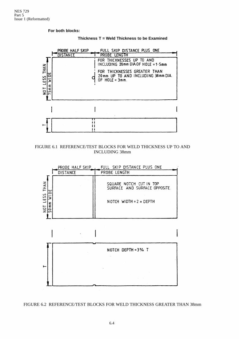
a. The calibration test piece ideally comprises a sample weld that simulates boththe geometry and material features of the weld to be examined. In the absenceof such a sample a machined test block of the same material and thickness asthe item under test can be used, see FIGURE 6.1 and FIGURE 6.2. Calibrationtargets consist of holes drilled normal to the examining surface or slots placedas shown. The calibration target type and size is to be as specified by the DesignAuthority who may require hole type targets for particular applicationsregardless of the thickness to be examined. As differences in the productionmaterial may cause attenuation, frequent checking is essential duringinspection to ensure the required working sensitivity is maintained.
b. The use of the Suppressor/Reject control will adversely affect the linearity of theamplifier. Suppression is therefore to be minimal. Should subsequentadjustment of this control be necessary changes in amplitude linearity are to benoted for consideration in defect sizing.
c. The instrument is to be calibrated to show a corner reflection of 20% FSD fromthe hole or notch with the probe index placed at full skip distance on the selectedtest block. When a distance amplitude curve is in use the reflection from thetarget is to be set to the curve.
d. Attenuation variation due to beam path length and the material is to be takeninto account before assessment of defect severity.
6.5 Method of Examination
a. Plate material adjacent to the weld through which the shear wave must pass isto be inspected in accordance with Clauses 4.4a. and 4.5a. and any defectiveareas recorded.
b. Shear wave scanning is to be carried out from both sides of the weld on one platesurface. Signal amplitude, location in the weld and probe movement andposition are to be taken into consideration in assessment of defect.
(1) Welds up to 12mm thick The shear wave scan may be carried out bydirecting the probe normal to the weld, with the probe index positionedat the optimum distance of twice the probe skip distance from the centreline of weld and bymoving the probe in a path parallel with the centre lineof weld. The probe may be oscillated as in Clause 6.5b.(2) provided thatfull weld coverage and defect location is achieved.
NES 729Part 5
Issue 1 (Reformatted)
6.3
(2) Welds over 12mm up to and including 50mm Shear wave inspectionmay be carried out in a series of scanning movements parallel with theweld at intervals not exceeding 60% of the transducer diameter or length.Alternatively the probe may be oscillated to and from the weld andprogressed along theweld at intervals not exceeding thewidth or diameterof the tranducer. The probe system is to be directed normal to the weldcentre line, preferably by mechanical means.
(3) Welds greater than 50mm Examination is to be considered in twostages. Stage one—scanning is to be carried out as required inClause 6.5(2). The effectiveness of this scan will be dependent upon theknowledge of the weld preparation detail; provided that it has first beenestablished that this scan will provide for the complete and effectiveexamination of the weld, the first stage scan will suffice.
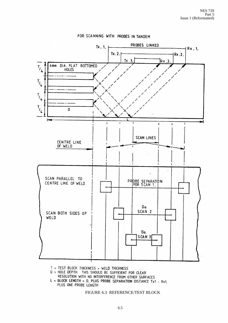
Stage two—this scan is to follow stage one when the effectiveness ofstage one scan is in doubt and in all situations where there is insufficientknowledge of the weld geometry. Stage two is to comprise a minimum ofthree separate scans on each side of the weld using transmitting (Tx) andreceiving (Rx) probes in tandem. The probes are to be suitably linked sothat the required distance between them for each scan is maintained(see FIGURE 6.3).
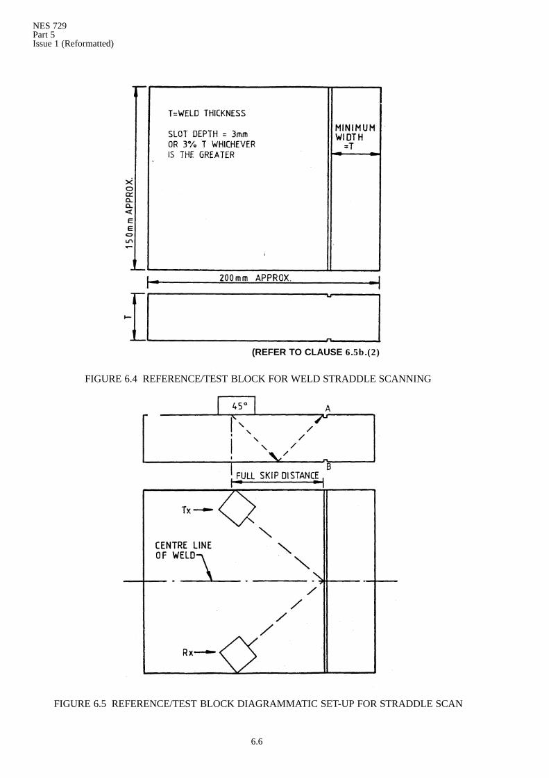
(4) For the detection of transverse defects irrespective of the materialthickness, direct inspection from the surface of the weld is preferred.Where the necessary surface preparation cannot be achieved, separatetransmitting and receiving probes are to be employed in a guided straddlescan, (see FIGURE 6.4 and FIGURE 6.5). The proper angle between theprobes is to be maintained by using a probe guide/jig for the purpose.
Note: Referring to FIGURE 6.4, determine the optimum angle between theprobes for the maximum response from top and bottom slots A and B inthe test block. Note the time base position of each slot response and spreadto a convenient scale relative to this block thickness. Adjust sensitivity togive a 20% FSD response from slot A (ie at full skip distance). Searchsensitivity is to take account of losses due to surface andbeam path length.
6.6 Records
a. Records of the weld examination are to include the results of the compressionalwave examination required by Clause 6.5a. Defect indications that result fromthe shear wave examination having a reflectivity of 5% FSD and greater are tobe recorded in sufficient detail to apply the acceptance standard inDG Ships/G/10000B.
NES 729Part 5Issue 1 (Reformatted)
6.4
FIGURE 6.1 REFERENCE/TEST BLOCKS FOR WELD THICKNESS UP TO ANDINCLUDING 38mm
FIGURE 6.2 REFERENCE/TEST BLOCKS FOR WELD THICKNESS GREATER THAN 38mm
For both blocks:
Thickness T = Weld Thickness to be Examined
NES 729Part 5
Issue 1 (Reformatted)
6.5
FIGURE 6.3 REFERENCE/TEST BLOCK
NES 729Part 5Issue 1 (Reformatted)
6.6
FIGURE 6.4 REFERENCE/TEST BLOCK FOR WELD STRADDLE SCANNING
FIGURE 6.5 REFERENCE/TEST BLOCK DIAGRAMMATIC SET-UP FOR STRADDLE SCAN
(REFER TO CLAUSE 6.5b.(2)
NES 729Part 5
Issue 1 (Reformatted)
7.1
7. TEE-BUTT WELDING
7.1 Application
a. Ultrasonic examination is applied to T-butt welds for the detection of defects inthe welding, and in the plate in the vicinity of the weld. Defects in the plate mayinclude defects of laminar form, and cracks in the toes of the welding orientatedat an angle with the plate surface.
b. Reference is made to:
(1) two types of examination:
(a) Complete examination—This requires the use of compressionalwave and shear wave techniques;
(b) Partial examination—This requires the use of compressional wavetechnique only. This application may be adequate to examinetable-web connections of fabricated frames.
(2) signal amplitudes DL and SL, which are defined as follows:
DL = Datum Line = 20% FSD from the relevant test block target;
SL = Six dB Line = DL minus 6dB of attenuation= 40% FSD from therelevant test block target.
7.2 Surface Preparation
a. The test surface is to be free from loose scale and any loose foreign matter whichcould interfere with the test. Shot blasted surfaces covered with a thin coatingof spray primer are usually satisfactory, but any successive layers of paintmustbe removed and the test surface lightly disc or belt sanded for reproducibleresults.
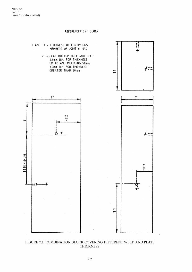
7.3 Test Blocks
a. The test block required for partial and or complete examination is as shown inFIGURE 7.1. The test block thickness is to be within ± 10% of the thickness ofthe T-butt jointmember that is under the probe and is used for the examination.
b. Probes
(1) Compressional wave probes are to be combined double type, of testfrequency 4 to 6MHz. The transducer area is to benot less than 100 squaremm. The transducer size is to conform to Clause 3.5a.
Note: This type of probe is subject to varying response with probe orientationand certain types of defect. To obviate this feature the acoustic baffle ofthe probe is to be positioned as follows:
Normal to centre line of weld when plotting weld width.Normal to centre line of weld when plotting defect width.Parallel to centre line of weld when plotting defect length.
(2) Shear wave probes are to be single or combined double type, of frequency2 to 4MHz. The transducer area is to be not less than 70 square mm. Thetransducer size is to conform to Clause 3.5a. The angle of refraction is tobe 45° .
Note: The use of probes with refracted angles greater than 45° will be necessary whenthe examination method in Clause 7.4a.(2) is used.
NES 729Part 5Issue 1 (Reformatted)
7.2
FIGURE 7.1 COMBINATION BLOCK COVERING DIFFERENT WELD AND PLATETHICKNESS
NES 729Part 5
Issue 1 (Reformatted)
7.3
7.4 Method of Examination
a. T-butt welds may be examined by:
(1) using the surface of the continuous member that is remote to the standingleg and scanning with compressional and shear waves. This is thepreferred method and it is to be used whenever possible.
(2) using both surfaces of the standing leg and the surface of the continuousmember that supports it and scanning with shear waves only.
7.5 Plotting Weld Width
a. Prior to the weld search using the preferred method the weld width is to beplotted. Use a compressional wave probe (see Clause b.(1)), and adjust the firstbottom echo from adjacent plate material to a convenient height eg 40% FSD.Move the probe slowly towards the weld and mark the weld edge at the probeindex position when this echo reduces to 20% FSD, ie 6dB drop. This procedureis to be repeated on both sides of the weld. Plot the weld edges at intervals notexceeding twice the thickness of the plate under the probe.
7.6 Calibration
a. Compressional wave probe Obtain DL (Clause 7.1b.) and SL from therelevant test block target, (see FIGURE 7.1). Both signal amplitude lines are tobe identifiable on the oscilloscope graticule.
b. Shear wave probe Note the horizontal displacement of the probe index fromthe test block target at probe half skip distance.
c. The time base is to be calibrated to a range equal to the combined thickness ofthe material and weld under the probe with the probe contact face set at zerowhen using compressional or shear wave probes.
7.7 Search Sensitivity
a. (1) Compressional wave probe The compressional wave searchsensitivity is to be established by the method used in Clauses 4.4a.(4) and4.4a.(5) and by using the attenuator figures obtained in displaying:
(a) a 20% FSD first backwall echo from an undrilled portion of the testblock;
(b) a 20% FSD echo from the test block target;
(c) a 20% FSD first backwall echo from the plate material adjacent tothe weld to be examined.
(2) Shear wave probe The shear wave search sensitivity will be establishedby displayed DL amplitude from the test block target corner—direct orfirst bounce depending on the technique to be used, and increasing thissignal by the difference in the attenuator figures obtained for operations(a) and (c) in Clause 7.7(1).
7.8 Search Scanning
a. Weld search scanning using compressional and shear wave probes is to be arectilinear scanning pattern with sufficient traverse to ensure completeexamination of the weld section and adjacent plate material. Forwardprogression is not to exceed one transducer width between each traverse. Forpartial examination the forward progression is to be as required by the DesignAuthority.
NES 729Part 5Issue 1 (Reformatted)
7.4
7.9 Defect Indication Measurement
a. The length and width of all defect indications of signal amplitude 20% FSD andgreater are to be measured using the 6dB-drop method (Clause 7.4a.). Theacoustic baffle of the compressional wave probe is to be positioned as requiredin Clause b.(1) The depth of defect is to be measured relative to the surface ofthe plate material remote to that under the probe.
7.10 Records
a. Defect indications of signal amplitude 20% FSD and greater are to be recordedtogether with their positions and defect dimensions, in sufficient detail to applyDG Ships/G/10000B.
NES 729Part 5
Issue 1 (Reformatted)
8.1
8. OVERLAY CLADDING
8.1 Application
a. The following requirements apply to the ultrasonic examination of the bondbetween weld deposited overlay cladding and the base material. Specificrequirements due to special shapes or manufacturing processes will be given inthe appropriate specification or weld procedure.
8.2 Surface Preparation
a. The test surface and reflecting surface are to be free from burrs, loose scale,machining or grinding particles or other loose foreign material. Surfaces are tobe smooth and sufficiently free from waviness to allow a proper and uniformexamination of all areas, at the required sensitivity level.
8.3 Calibration/Test Block
a. A cladded calibration test block is to be prepared using materials similar tothose used in the item to be examined. The test block base material is to be atleast 25mm thick. The metal cladding is to be deposited using the same weldingprocess and procedure to the same thickness and surface finish as the item tobe examined. A 3mm diameter flat bottomed hole is to be drilled through thebase material so that the bottom of the hole forms a reflecting surface at theinterface of the base material with the cladding material.
8.4 Sensitivity
a. The instrument is to be calibrated to display a 20% FSD signal from the testblock target.
8.5 Probes
a. Probes are to be twin crystal compressional wave of test frequency 2−6MHz.They are to comply with the requirements in Clause 3.5a.
8.6 Method of Examination
8.6.1 General
a. Scanning is to be carried out from the cladding surface and may be performedmanually or automatically by moving the probe in a directed path or bymovingthe material in a directed path with the probe held stationary. Scanning speedis to be uniform and at a rate determined during backwall can be used to obtaina back reflection be increased to show the back reflection and thus assureadequate coupling.
8.6.2 Manually deposited cladding
a. Manually deposited cladding is to be examined over the entire surface area.Adjacent scans are to be separated by approximately 80% of the probe crystalwidth to ensure adequate overlap.
8.6.3 Procedure tests
a. The examination of cladding procedure test samples is to be carried out inaccordance with Clause 8.6.2a.
8.6.4 Machine deposited cladding
a. Machine deposited cladding is to be examined along grid lines spaced at 50mmintervals and normal to the direction of welding. Additionally continuousscanning is to be applied to a width of 50mm from the edges of the perimeterof the cladded area and penetrations. Continuous scanning is also to be appliedto an area with a minimum radius of 150mm around any significant defect.
NES 729Part 5Issue 1 (Reformatted)
8.2
8.7 Records
a. Defect indications in the cladding are to be compared with the referencestandard in Clause 8.4a. for assessment. The position of each defect indicationin excess of the reference level is to be noted and explored to determine the areaand/or linear dimensions. Records of defect indications are to be sufficientlydetailed to apply the acceptance standard in DG Ships/G/10000B.
NES 729Part 5
Issue 1 (Reformatted)
9.1
9. BRAZED PIPE JOINTS
9.1 Application
a. The following requirements apply to the ultrasonic examination of capillarybrazed joints in piping systems to assess the area of bond between the pipe walland coupling fitting.
b. Reference is made to:
(1) Insert groove—The groove in the fitting socket prepared to contain thebrazing alloy.
(2) Land—The portion of the fitting adjacent to and/or between the insertgrooves.
9.2 Surface Preparation
a. The outer surface of the fitting is to be smooth and clean. Spelter, flux, paint orany other material is to be removed to provide a satisfactory surface for theexamination.
9.3 Probes
a. Probes are to be combined double compressional wave of test frequency2−6MHz. Selection of probe type will depend on the dimensions of the fittingand the width of lands. In view of the better resolution provided by focusedprobes on thin materials, their use is recommended where material thicknessallows.
9.4 Calibration
a. Test pieces are to be typical joint samples or manufactured sections of the samematerial and geometric configuration as the production items to be examined.The equipment is to be calibrated to display as distinct signals the:
(1) combined pipe and fitting thickness;
(2) fitting thickness in way of the joint;
(3) insert groove depth (if applicable).
The signal positions are to be clearly marked on the instrument graticule.
9.5 Sensitivity
a. Sensitivity is to be adjusted to obtain a FSD signal from the combined pipe walland fitting thickness, ie the bond condition, except for flange joints to whichClause 9.6a.(6) refers. For those couplings where the fitting and pipe wallthicknesses are similar a multiple echo pattern (not less than four) is to bedisplayed for the zero-bond condition in the test fitting. The amplitude of anyone signal is not to exceed FSD. The assessment of the condition of bond orno-bond is to be made with due regard to the complete trace pattern.
NES 729Part 5Issue 1 (Reformatted)
9.2
9.6 Method of Examination
a. (1) Recording is to proceed in parallel with the examination and to therequirements in Clauses 9.7a. and 9.7b.
(2) The acoustic barrier of the probe is to be placed parallel to the longitudinalaxis of the pipe and clear of the insert groove. Scanning is to be continuous,moving the probe steadily in a circumferential path without reversinguntil the scan of each division asmarked (Clauses 9.7a. and9.7b.) hasbeencompleted.
(3) Where possible the probe crystal is to be of a size that allows the joint tobe fully scanned in a number of passes without overlap. Where only onepass scanning is possible the probe edge is to be held close to the speltergroove edge during the scan.
(4) Fittings without insert grooves are to be scanned as a single land joint.
(5) Flange joints may be satisfactorily examined using the inner surface ofpipes depending on the size of probe available. The calibration procedurewill be similar to that for sleeved joints, ie successive echoes from the pipewall thickness will indicate zero bond. Bond condition will be indicated bythe absence of the pipe wall echoes or by their attenuation. The distancebetween the pipe inner wall and the outer radius of the flange may be toogreat to be shown in the display. Search sensitivity is to be set to showthree reflections from the zero-bond condition with the amplitude of thefirst not exceeding FSD. To ensure proper contact with the inner surfaceof the pipe, shaping of the probe may be necessary. This must be carriedout with care to avoid spurious signals and possibly confusedinterpretation. The recording procedure is to be as for sleeved joints.
(6) Hexagonal type fittings are to be examined by scanning the centre ofeach flat. The percentage bond for the joint is to be assessed by averagingthe results obtained.
9.7 Records
a. The use of tape as a means of recording as the examination proceeds isrecommended, but the use of alternative recording methods which can bedemonstrated and result in a comparable record are not excluded. Beforecommencing the examination apply a band of removable adhesive tape to thepipe adjacent to the fitting. Mark the tape to show equal divisions not exceeding25mm circumferentially in a clockwise direction as viewed from the pipe facingthe fitting. Permanently mark the 12 o’clock position on the fitting by etching,and mark the position on the tape. As the examination proceeds the tape is tobe marked to show:
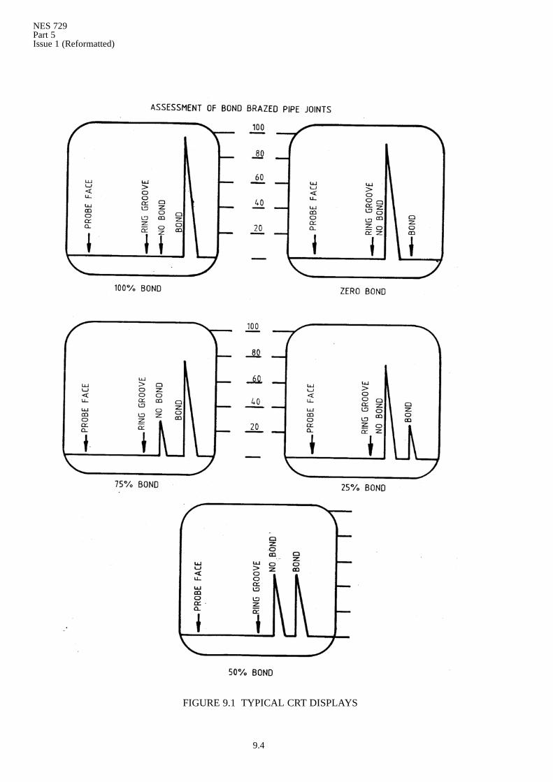
(1) the extent and percentage bond as determined by the difference in bondand zero-bond signal amplitudes for each division of each circumferentialscan. Typical examples are shown in FIGURE 9.1.
(2) ‘Not Tested’ areas marked NT, ie areas which cannot be examined due toinaccessibility;
(3) ‘No Ultrasonic Penetration’ areas marked NUP, ie areas which cannot beexamined due to fitting material characteristics and spurious signals;
(4) the number of circumferential scans on fittings without insert grooves;
(5) the relative positions of lands, ie outer,middle, inner, where insert groovesare a joint feature.
NES 729Part 5
Issue 1 (Reformatted)
9.3
b. The information recorded on the tape is to be transferred to a permanent recordwhich is required for each joint examined. The percentage bond assessment ofeach circumferential scan will be the average of the percentage bond figuresestablished for each division. The percentage bond of the joint will be assessedby averaging the percentage figures established for each circumferential scan.The final figure is to be stated to the nearest whole number.
NES 729Part 5Issue 1 (Reformatted)
9.4
FIGURE 9.1 TYPICAL CRT DISPLAYS
NES 729Part 5
Issue 1 (Reformatted)
10.1
10. PIPES AND TUBES
10.1 Application
a. The following requirements apply to the examination of pipes and tubes for thedetection of transverse and longitudinal discontinuities.
10.2 Calibration
a. A convenient length of pipe or tube of the same material and cross sectionaldimensions as that to be examined is to contain notch type targets, and is to beused as a calibration standard. For transverse type defects an internal andexternal notch is to be cut to the dimensions given in Clause 4.6a. except thatthe notch may extend wholly around the circumference. The notches are to beseparated by at least 40mm and located to permit calibration when the probeis positioned between the pipe or tube end and the nearest notch. Forlongitudinal type defects an internal and external notch is to be cut to thedimensions given in Clause 4.6a. parallel with the axis of the pipe. The notchesare to be separated by at least 30mm in a longitudinal direction. Each notch isto be clearly identifiable on the oscilloscope display.The positions of the internaltargets are to be marked on the pipe or tube outer surface.
10.3 Probes
a. Probes are to be shear wave and are to meet the requirements in Clause 3.5a.The test frequency selected is to be compatible with the material type and thewall thickness to be examined for the clear resolution of each calibration targetunder production conditions.
10.4 Method of Examination
a. Pipes and tubes are to be scanned parallel to the longitudinal axis for thedetection of transverse defects, and in a transverse direction for the detectionof longitudinal defects by advancing the probes assembly as the pipe or tube isrotated in such a way that the entire volume of the pipe wall is examined. Thespeed of pipe or tube rotation is to be reasonably uniform and at a rate consistentwith the maximum rotational speed of the calibration standard which enablesclear and definite resolution of the notch being presented. This speed is not tobe exceeded. Scanning may also be performed by rotating the part andautomatically indexing the probes assembly so that crystal overlap of at least10% is obtained on each successive pass. When the immersion method is usedthe examination conditions are to duplicate the calibration conditions asregards probes assembly alignment and wet or dry tube bore conditions. Ingeneral the exclusion of the immersion fluid from the bore improves thereproduction of the examination results. Each pipe is to be continuouslyscanned.
10.5 Records
a. The location extent and signal amplitudes of all indications in excess of theagreed sensitivity level are to be recorded.

NES 729Part 5Issue 1 (Reformatted)
10.2
NES 729Part 5
Issue 1 (Reformatted)
11.1
11. PIPE OR TUBE WALL THICKNESS MEASUREMENT
11.1 Application
a. The following requirements apply to the examination of pipe or tube todetermine wall thickness at the probe contact position. The method will notdetect pin holes.
11.2 Surface Preparation
a. The test surfaces are to be free from loose scale, rust and any other foreignmatter which could interfere with the examination.
11.3 Equipment
a. The requirements in Clause 5.a. are to apply.
11.4 Probes
a. Compressional wave probes suitable for the purpose are to be used. These maybe single or combined double types. The frequency is to be compatible with thematerial type and thickness of the pipe or tube to be examined. The probe sizeselected for the examination of pipes or tubes that are in service, will dependupon the configuration of the pipe or tube and the cross-sectional dimensions.
11.5 Calibration
a. The requirements in Clauses 5.a. to 5.1b. are to apply.
11.6 Method of Examination
a. Each pipe is to be placed on suitable rollers and rotated as the examinationproceeds. Each end is to be examined by turning the pipe through one fullrevolution with the probe at the end; additional scans are then to be made atintervals not exceeding 900mm along the entire length of the pipe unlessotherwise specified. In-service pipes and tubes are to be examined in accordancewith the applicable requirements of survey with particular attention to innerand outer radii of bends. The use of a probe holder to hold the probe normal tothe pipe surface during in-service examinations is recommended. In all cases,areas where the wall thickness approaches minimum tolerance are to besubjected to a complete search to determine the extent.
11.7 Records
a. Records are to provide for the positive identification of the pipe or tube,materialtype, coverage given and the location of areas where the wall thicknessapproaches minimum tolerance or otherwise as specified in the ContractDocuments.

NES 729Part 5Issue 1 (Reformatted)
11.2
NES 729Part 5
Issue 1 (Reformatted)
12.1
12. FORGINGS—INCLUDING FORGED, EXTRUDED AND WROUGHT BARS
12.1 Application
a. The wide variety of forgings in respect of material type, size and geometryrequired byMOD(PE) prevents the formulation of rigid ultrasonic examinationprocedures for general application. Specific procedures must take into accountthe material type and grain size, material attenuation factors, method ofmanufacture, and the type, location and probable distribution of defects likelyto be encountered. In the examination of non-ferrous bar, detection ofsub-surface defects is limited by the relationship between material grain size(approx diameter), the wavelength of the ultrasonic energy and the size of thesmallest detectable defect, since the diameter of the smallest detectable defectwill equate to one wavelength of the energy, and reduction in ultrasonicfrequency to overcome grain size problems will mean an increase in the size(width) of the smallest detectable defect. Ultrasonic test of non-ferrous barmayonly be practical where attenuation through thematerial does not preclude theuse of reflection techniques, and may only be meaningfully used for qualitypurposes where the maximum width of acceptable defect is not less than thoserelated to the diameter of the horizontal target holes inFIGURE 12.1. Barsmaycontain defects of width less than theminimum acceptance standard whichmaynot be detected and which could extend throughout the length of the bar.Diagnosis of defect indications in thick sections demands an accurateknowledge of probe characteristics. For the examination of steel forgings,excluding austenitic, BS 4124 Part 1 is to apply. For forgings to which BS 4124Part 1 cannot be applied, and extruded and wrought bars, the following clausesapply.
12.2 Surface Preparation
a. The condition of the test surface and the reflecting surface is not to causeinterference with the examination. Surfaces are to be free of loose scale, paintor other foreign matter. Rough machined surfaces are to be reduced using abroad-nosed tool to produce a regular smooth surface to avoid spuriousindications and excessive wear of the probe face.
12.3 Probes
a. Probe selection will depend on the geometry of the item to be examined,material type and grain size, and the area of probe contact surface. The best nearsurface resolution will be obtained using combined double compressional waveprobe and this characteristic is of value in the examination of areas subject tosubsequent machining. Generally the probe test frequency will be in the range2−6MHz but a lower frequency may be necessary to overcome the effects ofmaterial large grain structure and long beam path length. Shear wave probetechniques are to be used where specified. On bored items where the bore isinaccessible for examination with a compressional probe an appropriate shearwave technique is to be used. Shear wave is also to be used to cover areas wherethe shape of the item prevents comprehensive examination by compressionalwave.
NES 729Part 5Issue 1 (Reformatted)
12.2
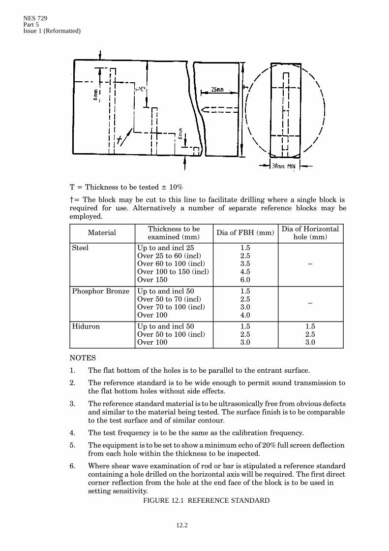
T = Thickness to be tested ± 10%
{= The block may be cut to this line to facilitate drilling where a single block isrequired for use. Alternatively a number of separate reference blocks may beemployed.
Material Thickness to beexamined (mm) Dia of FBH (mm) Dia of Horizontal
hole (mm)Steel Up to and incl 25
Over 25 to 60 (incl)Over 60 to 100 (incl)Over 100 to 150 (incl)Over 150
1.52.53.54.56.0
−
Phosphor Bronze Up to and incl 50Over 50 to 70 (incl)Over 70 to 100 (incl)Over 100
1.52.53.04.0
−
Hiduron Up to and incl 50Over 50 to 100 (incl)Over 100
1.52.53.0
1.52.53.0
NOTES
1. The flat bottom of the holes is to be parallel to the entrant surface.
2. The reference standard is to be wide enough to permit sound transmission tothe flat bottom holes without side effects.
3. The reference standardmaterial is to be ultrasonically free from obvious defectsand similar to the material being tested. The surface finish is to be comparableto the test surface and of similar contour.
4. The test frequency is to be the same as the calibration frequency.
5. The equipment is to be set to show aminimum echo of 20% full screen deflectionfrom each hole within the thickness to be inspected.
6. Where shear wave examination of rod or bar is stipulated a reference standardcontaining a hole drilled on the horizontal axis will be required. The first directcorner reflection from the hole at the end face of the block is to be used insetting sensitivity.
FIGURE 12.1 REFERENCE STANDARD
NES 729Part 5
Issue 1 (Reformatted)
12.3
12.4 Calibration
a. The reference standard FIGURE 12.1 is to apply. The attenuator figuresobtained from the adjustment of sensitivity to give 20% FSD signal amplitudefrom the backwall of the reference standard, each of the flat bottomed holes andthe backwall from the material under examination are to be recorded and usedto derive the minimum search sensitivity by the method of Clause 4.4a.(4),4.4a.(5), and 4.4a.(6). Sensitivity is to take account of local attenuation factorsand the depth of defect in the material when defect is evident.
12.5 Method of Examination
a. Wherever possible forgings are to be examined from surfaces so arranged thatthree major places are covered. The technique is to assure the detection ofdefects that are parallel to and normal to the principal axes. Defect areas andsuspect areas disclosed under these conditions are to be further evaluated fromthe surface opposite that used for their initial detection. Unless otherwisespecified in the Contract Documents the search unit is to be moved in parallelpaths. Each path is to overlap the previous and adjacent path by 10% of thewidth of the transducer. This procedure is to be repeated on all examiningsurfaces. Items of irregular section may require the preparation of a series ofexamination techniques for effective coverage.
12.6 Records
a. The size and location of all defect indications causing reflectivity of 20% FSDand greater are to be recorded and marked on the item as the examinationprogresses. Additionally in the examination of non-ferrous bars or rods thelocation of indications causing reflectivity of 5%−20% FSD are to be recorded.Records are to be sufficiently detailed to apply the relevant acceptance standardor as defined in the Contract Documents.

NES 729Part 5Issue 1 (Reformatted)
12.4
NES 729Part 5
Issue 1 (Reformatted)
13.1
13. CASTINGS
13.1 Application
a. The application of ultrasonic methods to the examination of ferrous andnon-ferrous castings requires the use of techniques that will enable defectassessment for the proper application of the acceptance standard. It is to berecognised that no single technique will suit all applications and also that thecasting material type and surface condition may inhibit useful and economicalapplication. The requirement to discriminate between defect types and theirvarying degrees of severity in respect of area and volume etc and their positionin the material will demand exacting techniques, and in view of the apparentdifficulties theMOD(PE) will require the validity of ultrasonic techniques to beconfirmed by radiographic examination of selected areas of castings where bothexamination methods can be usefully employed.
13.2 Surface Condition
a. The condition of the test surface and the reflecting surface is to permit effectiveultrasonic examination using the approved procedure. Shot blasted surfaceswill improve probe coupling efficiency. Rough machined castings may requirefurther preparation to provide a flat smooth surface to avoid spurious signalsand excessive wear of the probe face.
13.3 Probes
a. The choice of probes will be influenced by the casting material, geometry andthe type of defects to be detected. The use of both compressional wave and shearwave probes may be necessary in defect assessment (Clause 12.3a. will apply).
13.4 Calibration
a. Reference blocks as required are to be prepared from sound material and toconform to the requirements in Clause 3.6a.
13.5 Method of Examination
a. It will first be necessary to establish that the material grain structure andsurface finish permit adequate ultrasonic transmission for the properexamination of the area required. Each area will need to be checked for thispurpose by observing the backwall response using a compressional wave probeor a corner reflection using a shear wave probe.
Note: In the ‘as-cast’ condition the grain size of the material is large. Where thegrain diameter approaches ultrasonic wavelength high attenuation willoccur. In the heat treated condition the grain structure is refined with asubsequent reduction of attenuation.
b. The compressional wave search sensitivity level is to be as high as possible andconsistent with acceptable levels of reflections from material grain. Evidence ofdefect is to be cause for adjustment of sensitivity before attempting assessment,by taking account of its position below the surface and attenuation effects, andlocal probe transfer losses. Assessment of defect severity may necessarilycombine amplitude and attenuation methods for different defect types. Areasthat cause the backwall echo to reduce to 20% FSD and less with no evidenceof reflecting defect are, after a check of local surface condition and coupling, tobe marked on the casting as ‘attenuating defect areas’ as the examinationprogresses for subsequent inclusion in the record of test.

NES 729Part 5Issue 1 (Reformatted)
13.2
13.6 Assessment of Defects
a. The assessment of defect types and their severity as required for the properapplication of the acceptance standard DG Ships/PS/9010B may necessarilyrequire radiographic examination of the areas concerned to confirm ordetermine their acceptability.
NES 729Part 5
Issue 1 (Reformatted)
14.1
14. SAFETY
a. All equipment involving the use of main electrical supply is to conform to therelevant statutory requirements and safety regulations.
b. All examinations referred to in this NES are to be carried out with due regardto the applicable statutory requirements, safety regulations, and Codes ofPractice.

NES 729Part 5Issue 1 (Reformatted)
14.2
NES 729Part 5
Issue 1 (Reformatted)
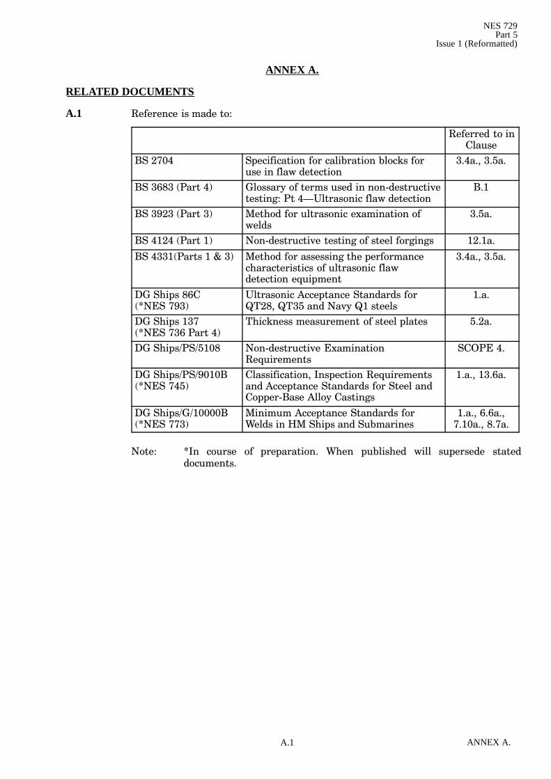
A.1 ANNEX A.
ANNEX A.
RELATED DOCUMENTS
A.1 Reference is made to:
Referred to inClause
BS 2704 Specification for calibration blocks foruse in flaw detection
3.4a., 3.5a.
BS 3683 (Part 4) Glossary of terms used in non-destructivetesting: Pt 4—Ultrasonic flaw detection
B.1
BS 3923 (Part 3) Method for ultrasonic examination ofwelds
3.5a.
BS 4124 (Part 1) Non-destructive testing of steel forgings 12.1a.
BS 4331(Parts 1 & 3) Method for assessing the performancecharacteristics of ultrasonic flawdetection equipment
3.4a., 3.5a.
DG Ships 86C(*NES 793)
Ultrasonic Acceptance Standards forQT28, QT35 and Navy Q1 steels
1.a.
DG Ships 137(*NES 736 Part 4)
Thickness measurement of steel plates 5.2a.
DG Ships/PS/5108 Non-destructive ExaminationRequirements
SCOPE 4.
DG Ships/PS/9010B(*NES 745)
Classification, Inspection Requirementsand Acceptance Standards for Steel andCopper-Base Alloy Castings
1.a., 13.6a.
DG Ships/G/10000B(*NES 773)
Minimum Acceptance Standards forWelds in HM Ships and Submarines
1.a., 6.6a.,7.10a., 8.7a.
Note: *In course of preparation. When published will supersede stateddocuments.

NES 729Part 5Issue 1 (Reformatted)
A.2ANNEX A.

NES 729Part 5
Issue 1 (Reformatted)
B.1 ANNEX B.
ANNEX B.
DEFINITIONS AND ABBREVIATIONS
B.1 BS 3683 (Part 4) is to apply to the terms in this NES.
Design Authority This term as used refers to that section or groupwithin the MOD that has overall responsibilityfor the material, item, structure, system orvessel concerned.
Examining Authority This term as used refers to the Company,Organization, Establishment or Naval Base thatcarries out the ultrasonic examinations withinthe scope of this NES.

NES 729Part 5Issue 1 (Reformatted)
B.2ANNEX B.
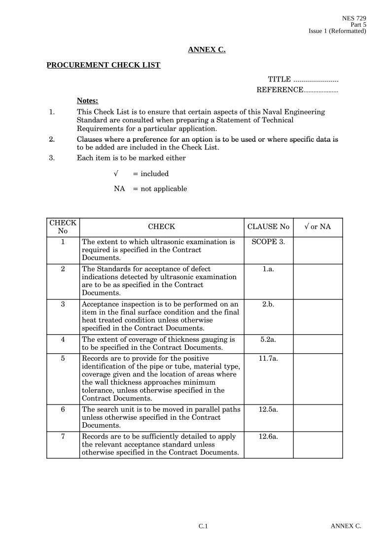
NES 729Part 5
Issue 1 (Reformatted)
C.1 ANNEX C.
ANNEX C.
PROCUREMENT CHECK LIST
TITLE .......................REFERENCE.....................
Notes:1. This Check List is to ensure that certain aspects of this Naval Engineering
Standard are consulted when preparing a Statement of TechnicalRequirements for a particular application.
2. Clauses where a preference for an option is to be used or where specific data is2. Clauses where a preference for an option is to be used or where specific data isto be added are included in the Check List.
3. Each item is to be marked either
! = included
NA = not applicable
CHECKNo CHECK CLAUSE No ! or NA
1 The extent to which ultrasonic examination isrequired is specified in the ContractDocuments.
SCOPE 3.
2 The Standards for acceptance of defectindications detected by ultrasonic examinationare to be as specified in the ContractDocuments.
1.a.
3 Acceptance inspection is to be performed on anitem in the final surface condition and the finalheat treated condition unless otherwisespecified in the Contract Documents.
2.b.
4 The extent of coverage of thickness gauging isto be specified in the Contract Documents.
5.2a.
5 Records are to provide for the positiveidentification of the pipe or tube, material type,coverage given and the location of areas wherethe wall thickness approaches minimumtolerance, unless otherwise specified in theContract Documents.
11.7a.
6 The search unit is to be moved in parallel pathsunless otherwise specified in the ContractDocuments.
12.5a.
7 Records are to be sufficiently detailed to applythe relevant acceptance standard unlessotherwise specified in the Contract Documents.
12.6a.

NES 729Part 5Issue 1 (Reformatted)
C.2ANNEX C.
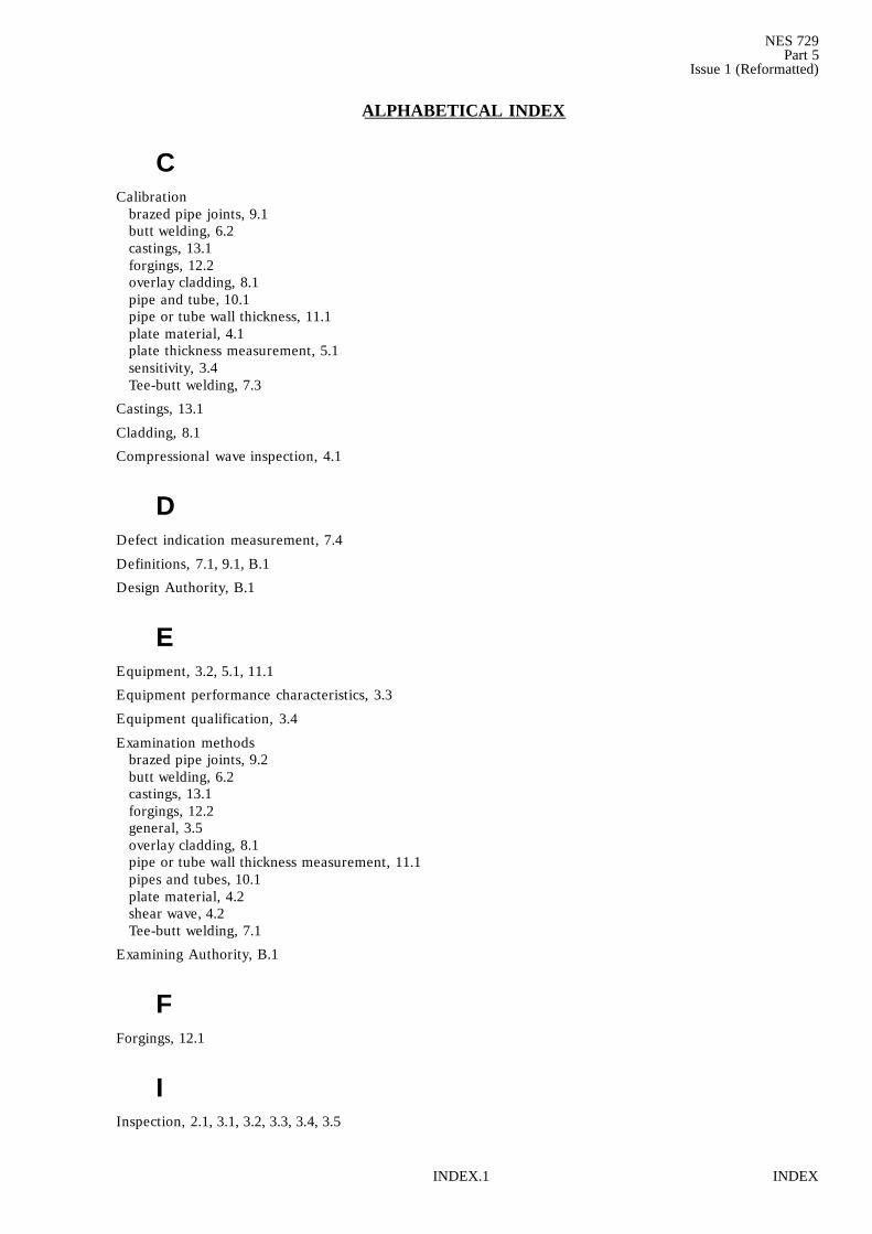
NES 729Part 5
Issue 1 (Reformatted)
INDEXINDEX.1
ALPHABETICAL INDEX
CCalibration
brazed pipe joints, 9.1butt welding, 6.2castings, 13.1forgings, 12.2overlay cladding, 8.1pipe and tube, 10.1pipe or tube wall thickness, 11.1plate material, 4.1plate thickness measurement, 5.1sensitivity, 3.4Tee-butt welding, 7.3
Castings, 13.1
Cladding, 8.1
Compressional wave inspection, 4.1
DDefect indication measurement, 7.4
Definitions, 7.1, 9.1, B.1
Design Authority, B.1
EEquipment, 3.2, 5.1, 11.1
Equipment performance characteristics, 3.3
Equipment qualification, 3.4
Examination methodsbrazed pipe joints, 9.2butt welding, 6.2castings, 13.1forgings, 12.2general, 3.5overlay cladding, 8.1pipe or tube wall thickness measurement, 11.1pipes and tubes, 10.1plate material, 4.2shear wave, 4.2Tee-butt welding, 7.1
Examining Authority, B.1
FForgings, 12.1
IInspection, 2.1, 3.1, 3.2, 3.3, 3.4, 3.5
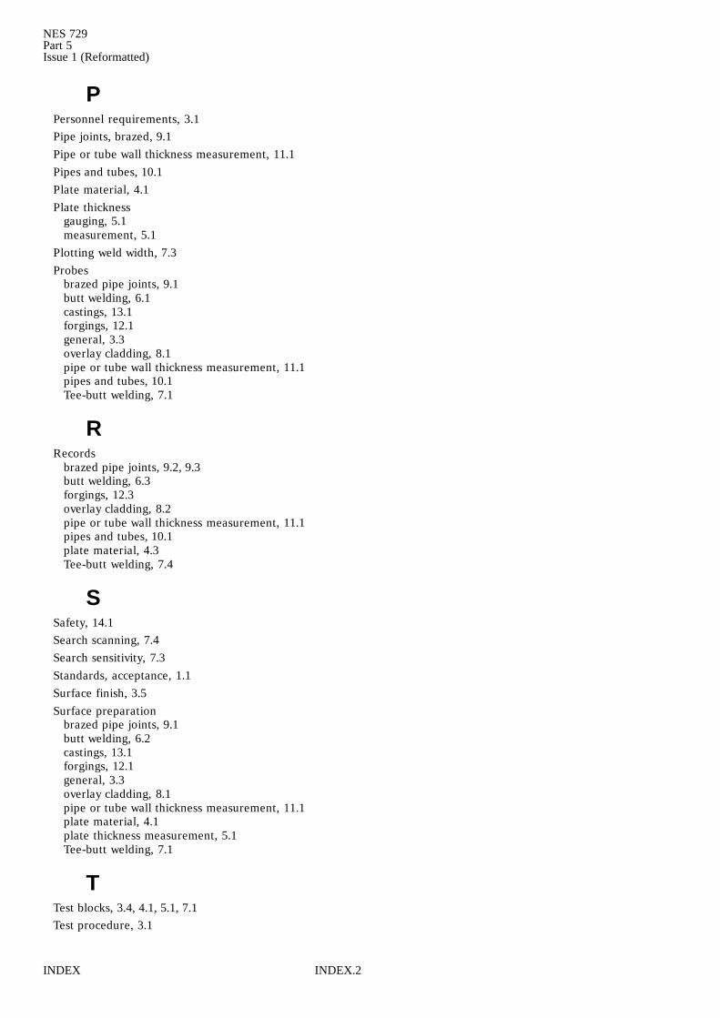
NES 729Part 5Issue 1 (Reformatted)
INDEX INDEX.2
PPersonnel requirements, 3.1Pipe joints, brazed, 9.1Pipe or tube wall thickness measurement, 11.1Pipes and tubes, 10.1Plate material, 4.1Plate thickness
gauging, 5.1measurement, 5.1
Plotting weld width, 7.3Probes
brazed pipe joints, 9.1butt welding, 6.1castings, 13.1forgings, 12.1general, 3.3overlay cladding, 8.1pipe or tube wall thickness measurement, 11.1pipes and tubes, 10.1Tee-butt welding, 7.1
RRecords
brazed pipe joints, 9.2, 9.3butt welding, 6.3forgings, 12.3overlay cladding, 8.2pipe or tube wall thickness measurement, 11.1pipes and tubes, 10.1plate material, 4.3Tee-butt welding, 7.4
SSafety, 14.1Search scanning, 7.4Search sensitivity, 7.3Standards, acceptance, 1.1Surface finish, 3.5Surface preparation
brazed pipe joints, 9.1butt welding, 6.2castings, 13.1forgings, 12.1general, 3.3overlay cladding, 8.1pipe or tube wall thickness measurement, 11.1plate material, 4.1plate thickness measurement, 5.1Tee-butt welding, 7.1
TTest blocks, 3.4, 4.1, 5.1, 7.1Test procedure, 3.1

NES 729Part 5
Issue 1 (Reformatted)
INDEXINDEX.3
WWelding
butt, 6.1Tee-butt, 7.1

NES 729Part 5Issue 1 (Reformatted)
INDEX INDEX.4

Inside Rear Cover
© Crown Copyright 2000
Copying Only as Agreed with DStan
Defence Standards are Published by and Obtainable from:
Defence Procurement AgencyAn Executive Agency of The Ministry of Defence
Directorate of StandardizationKentigern House65 Brown Street
GLASGOW G2 8EX
DStan Helpdesk
Tel 0141 224 2531/2 Fax 0141 224 2503
Internet e-mail [email protected]
File Reference
The DStan file reference relating to work on this standard is D/DStan/69/02/729.
Contract Requirements
When Defence Standards are incorporated into contracts users are responsible for their correctapplication and for complying with contractual and statutory requirements. Compliance witha Defence Standard does not in itself confer immunity from legal obligations.
Revision of Defence Standards
Defence Standards are revised as necessary by up issue or amendment. It is important thatusers of Defence Standards should ascertain that they are in possession of the latest issue oramendment. Information on all Defence Standards is contained in Def Stan 00-00 Standardsfor Defence Part 3 , Index of Standards for Defence Procurement Section 4 ‘Index of DefenceStandards and Defence Specifications’ published annually and supplemented regularly byStandards in Defence News (SID News). Any person who, when making use of a DefenceStandard encounters an inaccuracy or ambiguity is requested to notify the Directorate ofStandardization (DStan) without delay in order that the matter may be investigated andappropriate action taken.