non-destructive and semi-destructive diagnostics of
TRANSCRIPT
BULLETIN OF THE POLISH ACADEMY OF SCIENCESTECHNICAL SCIENCES, Vol. 63, No. 1, 2015DOI: 10.1515/bpasts-2015-0010
CIVIL ENGINEERING
Non-destructive and semi-destructive diagnostics of concrete
structures in assessment of their durability
J. HOŁA∗ , J. BIEŃ, Ł. SADOWSKI, and K. SCHABOWICZ
Faculty of Civil Engineering, Wrocław University of Technology, 27 Wybrzeże Wyspiańskiego St., 50-370 Wrocław, Poland
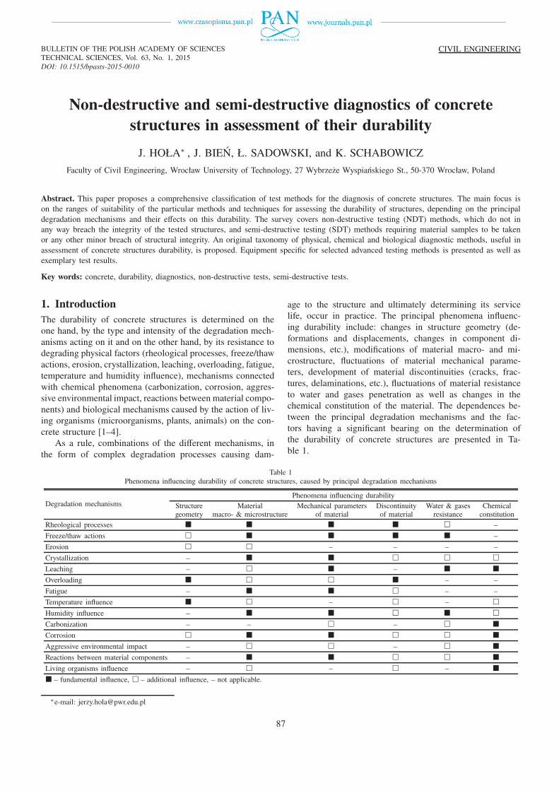
Abstract. This paper proposes a comprehensive classification of test methods for the diagnosis of concrete structures. The main focus ison the ranges of suitability of the particular methods and techniques for assessing the durability of structures, depending on the principaldegradation mechanisms and their effects on this durability. The survey covers non-destructive testing (NDT) methods, which do not inany way breach the integrity of the tested structures, and semi-destructive testing (SDT) methods requiring material samples to be takenor any other minor breach of structural integrity. An original taxonomy of physical, chemical and biological diagnostic methods, useful inassessment of concrete structures durability, is proposed. Equipment specific for selected advanced testing methods is presented as well asexemplary test results.
Key words: concrete, durability, diagnostics, non-destructive tests, semi-destructive tests.
1. Introduction
The durability of concrete structures is determined on theone hand, by the type and intensity of the degradation mech-anisms acting on it and on the other hand, by its resistance todegrading physical factors (rheological processes, freeze/thawactions, erosion, crystallization, leaching, overloading, fatigue,temperature and humidity influence), mechanisms connectedwith chemical phenomena (carbonization, corrosion, aggres-sive environmental impact, reactions between material compo-nents) and biological mechanisms caused by the action of liv-ing organisms (microorganisms, plants, animals) on the con-crete structure [1–4].
As a rule, combinations of the different mechanisms, inthe form of complex degradation processes causing dam-
age to the structure and ultimately determining its servicelife, occur in practice. The principal phenomena influenc-ing durability include: changes in structure geometry (de-formations and displacements, changes in component di-mensions, etc.), modifications of material macro- and mi-crostructure, fluctuations of material mechanical parame-ters, development of material discontinuities (cracks, frac-tures, delaminations, etc.), fluctuations of material resistanceto water and gases penetration as well as changes in thechemical constitution of the material. The dependences be-tween the principal degradation mechanisms and the fac-tors having a significant bearing on the determination ofthe durability of concrete structures are presented in Ta-ble 1.
Table 1Phenomena influencing durability of concrete structures, caused by principal degradation mechanisms
Degradation mechanismsPhenomena influencing durability
Structuregeometry
Materialmacro- & microstructure
Mechanical parametersof material
Discontinuityof material
Water & gasesresistance
Chemicalconstitution
Rheological processes � � � � � –
Freeze/thaw actions � � � � � –
Erosion � � – – – –
Crystallization – � � � � �
Leaching – � � – � �
Overloading � � � � – –
Fatigue – � � � – –
Temperature influence � � – � – �
Humidity influence – � � � � �
Carbonization – – � – � �
Corrosion � � � � � �
Aggressive environmental impact – � � – � �
Reactions between material components – � � � � �
Living organisms influence – � – � – �
� – fundamental influence, � – additional influence, – not applicable.
∗e-mail: [email protected]
87
J. Hoła, J. Bień, Ł. Sadowski, and K. Schabowicz
In the further part of this paper an innovative comprehen-sive classification of the investigative methods and techniquesused in the diagnosis of the durability of concrete structuresis proposed. Non-destructive testing (NDT) methods, whichdo not in any way breach the integrity of the tested structure,and semi-destructive testing (SDT) methods requiring mater-ial samples to be taken or any other minor breach of structureintegrity, have been distinguished.
2. Taxonomy of NDT methods
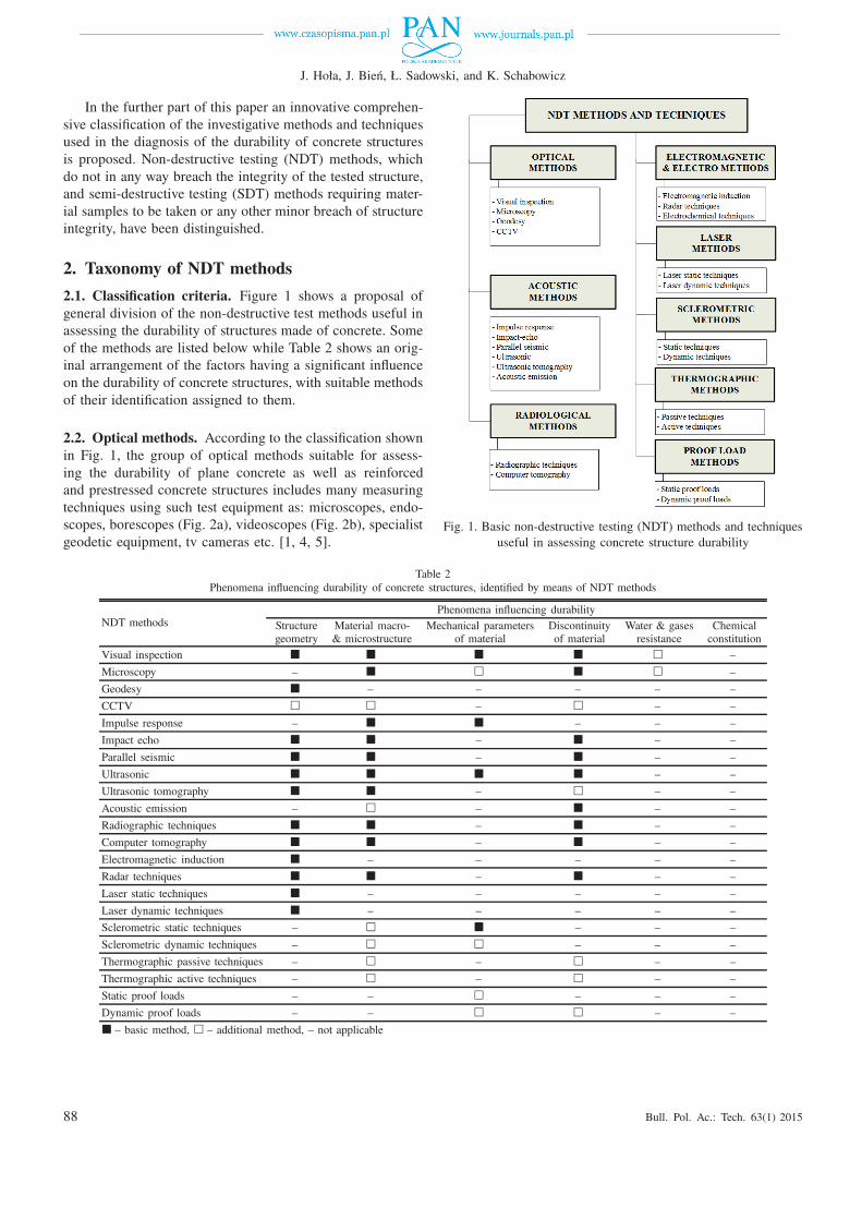
2.1. Classification criteria. Figure 1 shows a proposal ofgeneral division of the non-destructive test methods useful inassessing the durability of structures made of concrete. Someof the methods are listed below while Table 2 shows an orig-inal arrangement of the factors having a significant influenceon the durability of concrete structures, with suitable methodsof their identification assigned to them.
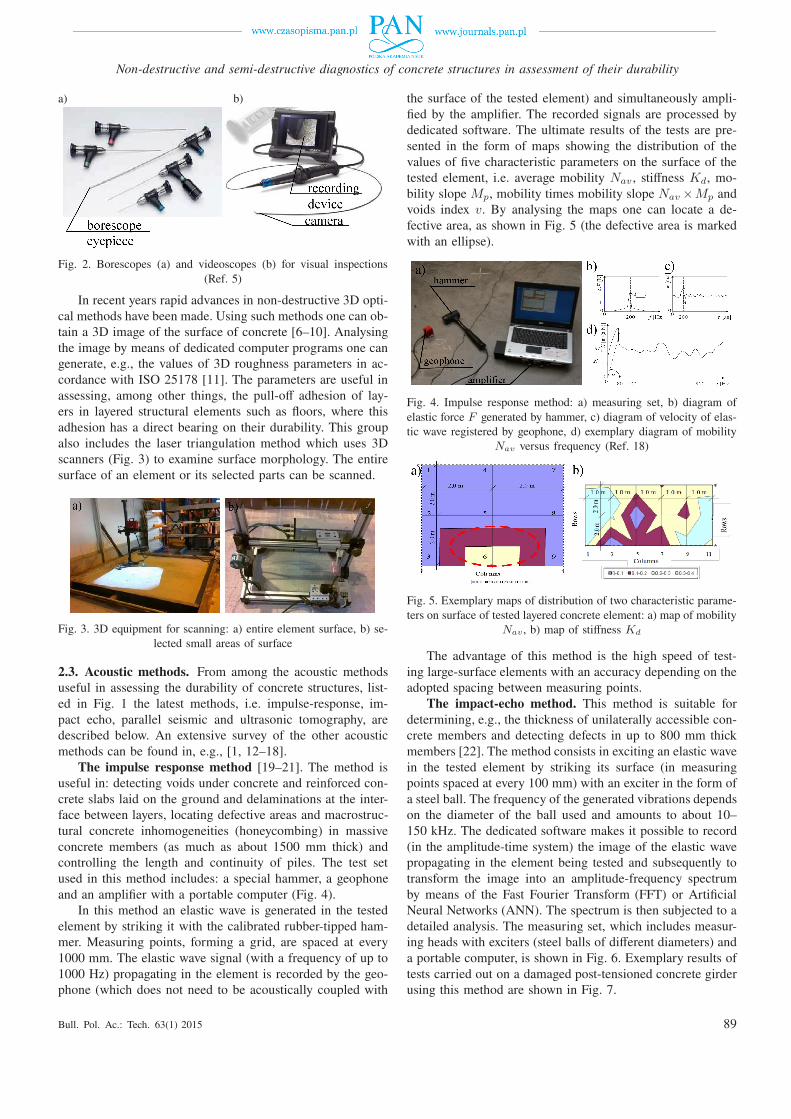
2.2. Optical methods. According to the classification shownin Fig. 1, the group of optical methods suitable for assess-ing the durability of plane concrete as well as reinforcedand prestressed concrete structures includes many measuringtechniques using such test equipment as: microscopes, endo-scopes, borescopes (Fig. 2a), videoscopes (Fig. 2b), specialistgeodetic equipment, tv cameras etc. [1, 4, 5].
Fig. 1. Basic non-destructive testing (NDT) methods and techniquesuseful in assessing concrete structure durability
Table 2Phenomena influencing durability of concrete structures, identified by means of NDT methods
NDT methodsPhenomena influencing durability
Structuregeometry
Material macro-& microstructure
Mechanical parametersof material
Discontinuityof material
Water & gasesresistance
Chemicalconstitution
Visual inspection � � � � � –
Microscopy – � � � � –
Geodesy � – – – – –
CCTV � � – � – –
Impulse response – � � – – –
Impact echo � � – � – –
Parallel seismic � � – � – –
Ultrasonic � � � � – –
Ultrasonic tomography � � – � – –
Acoustic emission – � – � – –
Radiographic techniques � � – � – –
Computer tomography � � – � – –
Electromagnetic induction � – – – – –
Radar techniques � � – � – –
Laser static techniques � – – – – –
Laser dynamic techniques � – – – – –
Sclerometric static techniques – � � – – –
Sclerometric dynamic techniques – � � – – –
Thermographic passive techniques – � – � – –
Thermographic active techniques – � – � – –
Static proof loads – – � – – –
Dynamic proof loads – – � � – –
� – basic method, � – additional method, – not applicable
88 Bull. Pol. Ac.: Tech. 63(1) 2015
Non-destructive and semi-destructive diagnostics of concrete structures in assessment of their durability
a) b)
Fig. 2. Borescopes (a) and videoscopes (b) for visual inspections(Ref. 5)
In recent years rapid advances in non-destructive 3D opti-cal methods have been made. Using such methods one can ob-tain a 3D image of the surface of concrete [6–10]. Analysingthe image by means of dedicated computer programs one cangenerate, e.g., the values of 3D roughness parameters in ac-cordance with ISO 25178 [11]. The parameters are useful inassessing, among other things, the pull-off adhesion of lay-ers in layered structural elements such as floors, where thisadhesion has a direct bearing on their durability. This groupalso includes the laser triangulation method which uses 3Dscanners (Fig. 3) to examine surface morphology. The entiresurface of an element or its selected parts can be scanned.
Fig. 3. 3D equipment for scanning: a) entire element surface, b) se-lected small areas of surface
2.3. Acoustic methods. From among the acoustic methodsuseful in assessing the durability of concrete structures, list-ed in Fig. 1 the latest methods, i.e. impulse-response, im-pact echo, parallel seismic and ultrasonic tomography, aredescribed below. An extensive survey of the other acousticmethods can be found in, e.g., [1, 12–18].
The impulse response method [19–21]. The method isuseful in: detecting voids under concrete and reinforced con-crete slabs laid on the ground and delaminations at the inter-face between layers, locating defective areas and macrostruc-tural concrete inhomogeneities (honeycombing) in massiveconcrete members (as much as about 1500 mm thick) andcontrolling the length and continuity of piles. The test setused in this method includes: a special hammer, a geophoneand an amplifier with a portable computer (Fig. 4).
In this method an elastic wave is generated in the testedelement by striking it with the calibrated rubber-tipped ham-mer. Measuring points, forming a grid, are spaced at every1000 mm. The elastic wave signal (with a frequency of up to1000 Hz) propagating in the element is recorded by the geo-phone (which does not need to be acoustically coupled with
the surface of the tested element) and simultaneously ampli-fied by the amplifier. The recorded signals are processed bydedicated software. The ultimate results of the tests are pre-sented in the form of maps showing the distribution of thevalues of five characteristic parameters on the surface of thetested element, i.e. average mobility Nav , stiffness Kd, mo-bility slope Mp, mobility times mobility slope Nav ×Mp andvoids index v. By analysing the maps one can locate a de-fective area, as shown in Fig. 5 (the defective area is markedwith an ellipse).
Fig. 4. Impulse response method: a) measuring set, b) diagram ofelastic force F generated by hammer, c) diagram of velocity of elas-tic wave registered by geophone, d) exemplary diagram of mobility
Nav versus frequency (Ref. 18)
Fig. 5. Exemplary maps of distribution of two characteristic parame-ters on surface of tested layered concrete element: a) map of mobility
Nav , b) map of stiffness Kd
The advantage of this method is the high speed of test-ing large-surface elements with an accuracy depending on theadopted spacing between measuring points.
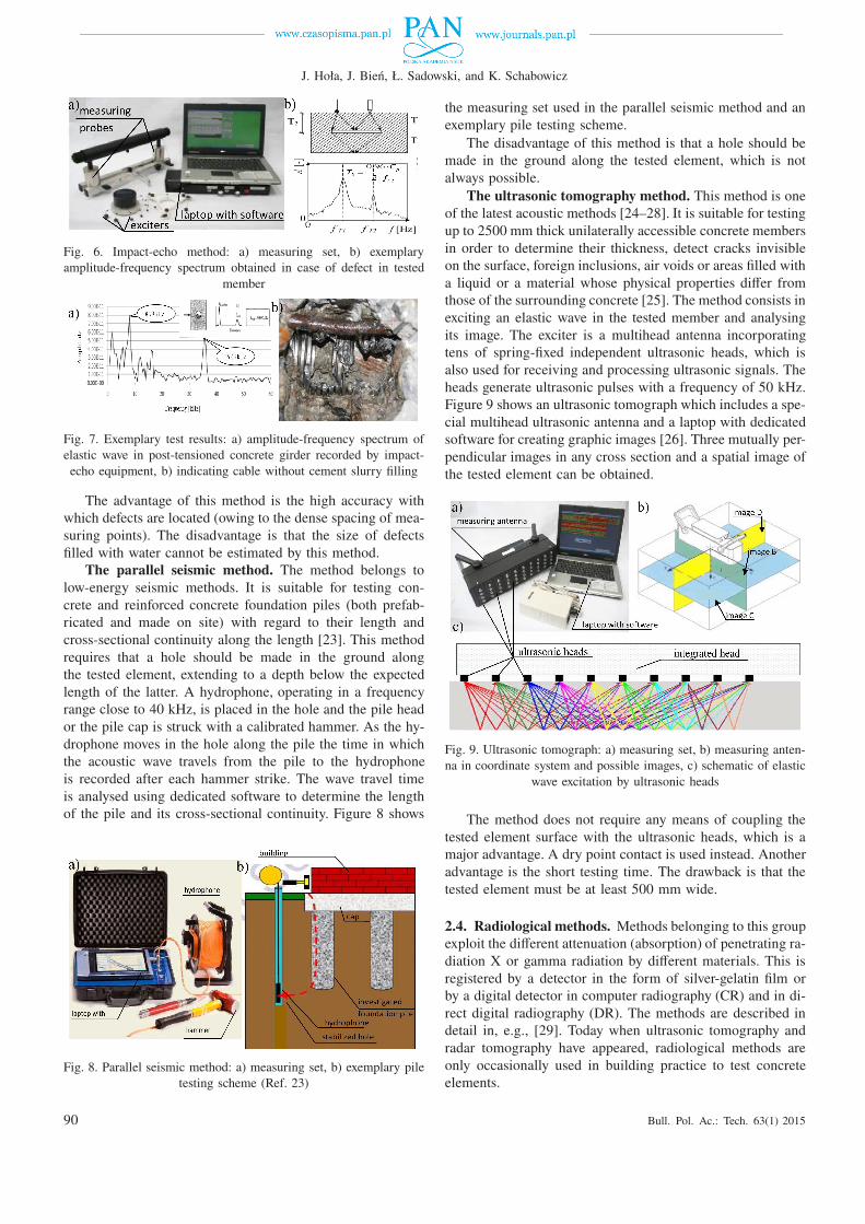
The impact-echo method. This method is suitable fordetermining, e.g., the thickness of unilaterally accessible con-crete members and detecting defects in up to 800 mm thickmembers [22]. The method consists in exciting an elastic wavein the tested element by striking its surface (in measuringpoints spaced at every 100 mm) with an exciter in the form ofa steel ball. The frequency of the generated vibrations dependson the diameter of the ball used and amounts to about 10–150 kHz. The dedicated software makes it possible to record(in the amplitude-time system) the image of the elastic wavepropagating in the element being tested and subsequently totransform the image into an amplitude-frequency spectrumby means of the Fast Fourier Transform (FFT) or ArtificialNeural Networks (ANN). The spectrum is then subjected to adetailed analysis. The measuring set, which includes measur-ing heads with exciters (steel balls of different diameters) anda portable computer, is shown in Fig. 6. Exemplary results oftests carried out on a damaged post-tensioned concrete girderusing this method are shown in Fig. 7.
Bull. Pol. Ac.: Tech. 63(1) 2015 89
J. Hoła, J. Bień, Ł. Sadowski, and K. Schabowicz
Fig. 6. Impact-echo method: a) measuring set, b) exemplaryamplitude-frequency spectrum obtained in case of defect in tested
member
Fig. 7. Exemplary test results: a) amplitude-frequency spectrum ofelastic wave in post-tensioned concrete girder recorded by impact-echo equipment, b) indicating cable without cement slurry filling
The advantage of this method is the high accuracy withwhich defects are located (owing to the dense spacing of mea-suring points). The disadvantage is that the size of defectsfilled with water cannot be estimated by this method.
The parallel seismic method. The method belongs tolow-energy seismic methods. It is suitable for testing con-crete and reinforced concrete foundation piles (both prefab-ricated and made on site) with regard to their length andcross-sectional continuity along the length [23]. This methodrequires that a hole should be made in the ground alongthe tested element, extending to a depth below the expectedlength of the latter. A hydrophone, operating in a frequencyrange close to 40 kHz, is placed in the hole and the pile heador the pile cap is struck with a calibrated hammer. As the hy-drophone moves in the hole along the pile the time in whichthe acoustic wave travels from the pile to the hydrophoneis recorded after each hammer strike. The wave travel timeis analysed using dedicated software to determine the lengthof the pile and its cross-sectional continuity. Figure 8 shows
Fig. 8. Parallel seismic method: a) measuring set, b) exemplary piletesting scheme (Ref. 23)
the measuring set used in the parallel seismic method and anexemplary pile testing scheme.
The disadvantage of this method is that a hole should bemade in the ground along the tested element, which is notalways possible.
The ultrasonic tomography method. This method is oneof the latest acoustic methods [24–28]. It is suitable for testingup to 2500 mm thick unilaterally accessible concrete membersin order to determine their thickness, detect cracks invisibleon the surface, foreign inclusions, air voids or areas filled witha liquid or a material whose physical properties differ fromthose of the surrounding concrete [25]. The method consists inexciting an elastic wave in the tested member and analysingits image. The exciter is a multihead antenna incorporatingtens of spring-fixed independent ultrasonic heads, which isalso used for receiving and processing ultrasonic signals. Theheads generate ultrasonic pulses with a frequency of 50 kHz.Figure 9 shows an ultrasonic tomograph which includes a spe-cial multihead ultrasonic antenna and a laptop with dedicatedsoftware for creating graphic images [26]. Three mutually per-pendicular images in any cross section and a spatial image ofthe tested element can be obtained.
Fig. 9. Ultrasonic tomograph: a) measuring set, b) measuring anten-na in coordinate system and possible images, c) schematic of elastic
wave excitation by ultrasonic heads
The method does not require any means of coupling thetested element surface with the ultrasonic heads, which is amajor advantage. A dry point contact is used instead. Anotheradvantage is the short testing time. The drawback is that thetested element must be at least 500 mm wide.
2.4. Radiological methods. Methods belonging to this groupexploit the different attenuation (absorption) of penetrating ra-diation X or gamma radiation by different materials. This isregistered by a detector in the form of silver-gelatin film orby a digital detector in computer radiography (CR) and in di-rect digital radiography (DR). The methods are described indetail in, e.g., [29]. Today when ultrasonic tomography andradar tomography have appeared, radiological methods areonly occasionally used in building practice to test concreteelements.
90 Bull. Pol. Ac.: Tech. 63(1) 2015
Non-destructive and semi-destructive diagnostics of concrete structures in assessment of their durability
2.5. Electromagnetic methods. From among the non-destructive electromagnetic methods (Fig. 1) suitable for as-sessing the durability of concrete structures the latest groundpenetrating method (GPR) is described here. GPR is used todetermine or detect: thickness, delaminations, large air voids,extensive defects and the location of reinforcement bars inunilaterally accessible concrete and reinforced concrete mem-bers [30]. Depending on the purpose for which the radar isused, transmitting/receiving heads (antennas) generate elec-tromagnetic waves with a frequency of 0.1–2.5 GHz. Theyhave wheels and can drive on the surface of tested elements.They are connected via a cable or radio with a data logger.A typical radar set is shown in Fig. 10.
Fig. 10. Radar set (a) and exemplary image showing distribution ofreinforcement in representative reinforced concrete element (b)
The advantage of this method is that members with largesurfaces can be quickly tested, especially to locate reinforce-ment. Its disadvantage is the low accuracy of determiningreinforcement diameter and concrete cover thickness.
Non-destructive electrochemical techniques, mainly suit-able for evaluating the degree of corrosion of the reinforce-ment in reinforced concrete structures, include the resistancetechnique [31]. The most popular are the methods of measur-ing the resistance of the concrete cover, including the non-destructive four-point Wenner method [32]. In recent yearsmodifications of this method have appeared in the literature[33–35]. The method presented in Fig. 11 takes advantage ofthe short-circuit effect of a steel bar on resistivity rather thanavoiding it [36, 37]. Galvanostatic resistivity measurementsare taken using a modified electrode array. To ensure thestability of potential during the 30 sec equilibrium period,the two inner standard resistivity probes are replaced withtwo copper-copper sulphate reference electrodes (Fig. 11a).A small current signal is provided by a standard laboratory
Fig. 11. New corrosion assessing method: a) equipment (Ref. 36),b) exemplary contour plot of concrete resistivity (Ref. 37)
galvanostat and the resulting change in potential is measuredusing a high impedance voltmeter.
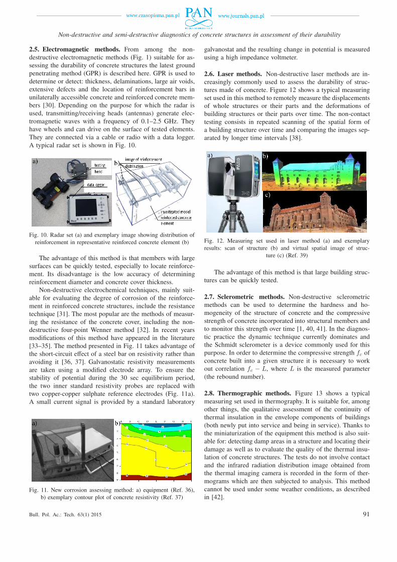
2.6. Laser methods. Non-destructive laser methods are in-creasingly commonly used to assess the durability of struc-tures made of concrete. Figure 12 shows a typical measuringset used in this method to remotely measure the displacementsof whole structures or their parts and the deformations ofbuilding structures or their parts over time. The non-contacttesting consists in repeated scanning of the spatial form ofa building structure over time and comparing the images sep-arated by longer time intervals [38].
Fig. 12. Measuring set used in laser method (a) and exemplaryresults: scan of structure (b) and virtual spatial image of struc-
ture (c) (Ref. 39)
The advantage of this method is that large building struc-tures can be quickly tested.
2.7. Sclerometric methods. Non-destructive sclerometricmethods can be used to determine the hardness and ho-mogeneity of the structure of concrete and the compressivestrength of concrete incorporated into structural members andto monitor this strength over time [1, 40, 41]. In the diagnos-tic practice the dynamic technique currently dominates andthe Schmidt sclerometer is a device commonly used for thispurpose. In order to determine the compressive strength fc ofconcrete built into a given structure it is necessary to workout correlation fc − L, where L is the measured parameter(the rebound number).
2.8. Thermographic methods. Figure 13 shows a typicalmeasuring set used in thermography. It is suitable for, amongother things, the qualitative assessment of the continuity ofthermal insulation in the envelope components of buildings(both newly put into service and being in service). Thanks tothe miniaturization of the equipment this method is also suit-able for: detecting damp areas in a structure and locating theirdamage as well as to evaluate the quality of the thermal insu-lation of concrete structures. The tests do not involve contactand the infrared radiation distribution image obtained fromthe thermal imaging camera is recorded in the form of ther-mograms which are then subjected to analysis. This methodcannot be used under some weather conditions, as describedin [42].
Bull. Pol. Ac.: Tech. 63(1) 2015 91
J. Hoła, J. Bień, Ł. Sadowski, and K. Schabowicz
Fig. 13. Thermal imaging camera (a) and typical thermogram (b)
2.9. Proof loads. Tests of concrete structures under static ordynamic proof loads can supply information useful in the as-sessment of their durability. This particularly applies to impor-tant structures (e.g. bridges) subjected to periodically repeatedloads or fitted with systems continuously monitoring changesin their condition [4, 43].
3. Taxonomy of SDT methods
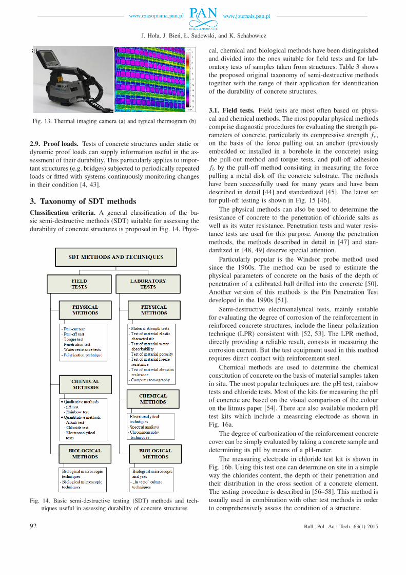
Classification criteria. A general classification of the ba-sic semi-destructive methods (SDT) suitable for assessing thedurability of concrete structures is proposed in Fig. 14. Physi-
Fig. 14. Basic semi-destructive testing (SDT) methods and tech-niques useful in assessing durability of concrete structures
cal, chemical and biological methods have been distinguishedand divided into the ones suitable for field tests and for lab-oratory tests of samples taken from structures. Table 3 showsthe proposed original taxonomy of semi-destructive methodstogether with the range of their application for identificationof the durability of concrete structures.
3.1. Field tests. Field tests are most often based on physi-cal and chemical methods. The most popular physical methodscomprise diagnostic procedures for evaluating the strength pa-rameters of concrete, particularly its compressive strength fc,on the basis of the force pulling out an anchor (previouslyembedded or installed in a borehole in the concrete) usingthe pull-out method and torque tests, and pull-off adhesionfb by the pull-off method consisting in measuring the forcepulling a metal disk off the concrete substrate. The methodshave been successfully used for many years and have beendescribed in detail [44] and standardized [45]. The latest setfor pull-off testing is shown in Fig. 15 [46].
The physical methods can also be used to determine theresistance of concrete to the penetration of chloride salts aswell as its water resistance. Penetration tests and water resis-tance tests are used for this purpose. Among the penetrationmethods, the methods described in detail in [47] and stan-dardized in [48, 49] deserve special attention.
Particularly popular is the Windsor probe method usedsince the 1960s. The method can be used to estimate thephysical parameters of concrete on the basis of the depth ofpenetration of a calibrated ball drilled into the concrete [50].Another version of this methods is the Pin Penetration Testdeveloped in the 1990s [51].
Semi-destructive electroanalytical tests, mainly suitablefor evaluating the degree of corrosion of the reinforcement inreinforced concrete structures, include the linear polarizationtechnique (LPR) consistent with [52, 53]. The LPR method,directly providing a reliable result, consists in measuring thecorrosion current. But the test equipment used in this methodrequires direct contact with reinforcement steel.
Chemical methods are used to determine the chemicalconstitution of concrete on the basis of material samples takenin situ. The most popular techniques are: the pH test, rainbowtests and chloride tests. Most of the kits for measuring the pHof concrete are based on the visual comparison of the colouron the litmus paper [54]. There are also available modern pHtest kits which include a measuring electrode as shown inFig. 16a.
The degree of carbonization of the reinforcement concretecover can be simply evaluated by taking a concrete sample anddetermining its pH by means of a pH-meter.
The measuring electrode in chloride test kit is shown inFig. 16b. Using this test one can determine on site in a simpleway the chlorides content, the depth of their penetration andtheir distribution in the cross section of a concrete element.The testing procedure is described in [56–58]. This method isusually used in combination with other test methods in orderto comprehensively assess the condition of a structure.
92 Bull. Pol. Ac.: Tech. 63(1) 2015
Non-destructive and semi-destructive diagnostics of concrete structures in assessment of their durability
Table 3Phenomena influencing durability of concrete structures, identified by means of SDT methods
SDT methodsPhenomena influencing durability
Structuregeometry
Material macro-& microstructure
Mechanical parametersof material
Discontinuityof material
Water & gasesresistance
Chemicalconstitution
Fieldtests
Pull-out tests – – � – – –
Pull-off tests – – � – – –
Torque tests – – � – – –
Penetration tests – – � – – –
Water resistance tests – � – – � –
Polarization technique – – – – – �
pH tests – – – – – �
Rainbow tests – – – – – �
Alkali tests – – – – – �
Chloride tests – – – – – �
Electroanalytical tests – – – – – �
Biological macroscopic techniques – � – � – –
Biological microscopic techniques – � – � – –
Laboratorytests
Material strength tests – – � – – –
Tests of material elastic characteristics – – � – – –
Tests of material water absorbability – � – – � –
Tests of material porosity – � – – � –
Tests of material freeze resistance – – � – – –
Tests of material abrasion resistance – � � – – –
Electroanalytical techniques – – – – – �
Spectral analysis – – – – – �
Chromatography techniques – – – – – �
Biological microscopic analyses – � – � – –
“In vitro” culture techniques – � – – – �
� – basic method, �– additional method, – not applicable
Fig. 15. View of: a) latest set for pull-off testing, b) test being per-formed (Ref. 46)
a) b)
Fig. 16. View of: a) test being carried out by latest kit for estimatingpH of concrete (Ref. 55), b) measuring electrode in chloride test kit
(Ref. 57)
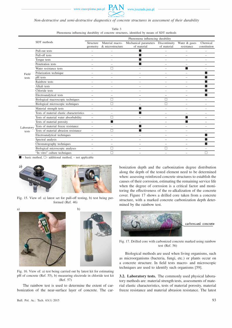
The rainbow test is used to determine the extent of car-bonization of the near-surface layer of concrete. The car-
bonization depth and the carbonization degree distributionalong the depth of the tested element need to be determinedwhen: assessing reinforced concrete structures to establish thecauses of their corrosion, estimating the remaining service lifewhen the degree of corrosion is a critical factor and moni-toring the effectiveness of the re-alkalization of the concretecover. Figure 17 shows a drilled core taken from a concretestructure, with a marked concrete carbonization depth deter-mined by the rainbow test.
Fig. 17. Drilled core with carbonized concrete marked using rainbowtest (Ref. 56)
Biological methods are used when living organisms, suchas microorganisms (bacteria, fungi, etc.) or plants occur ona concrete structure. In field tests macro- and microscopictechniques are used to identify such organisms [59].
3.2. Laboratory tests. The commonly used physical labora-tory methods are: material strength tests, assessments of mate-rial elastic characteristics, tests of material porosity, materialfreeze resistance and material abrasion resistance. The latest
Bull. Pol. Ac.: Tech. 63(1) 2015 93
J. Hoła, J. Bień, Ł. Sadowski, and K. Schabowicz
method in this group is computer microtomography, whichmakes it possible to reconstruct a three-dimensional image ofmaterial microstructure of the tested sample on the basis oftwo-dimensional projections obtained by scanning it with abeam of X-radiation [60] (Fig. 18).
Fig. 18. View of computer X-ray microtomography test setup (a) andobtained image of concrete sample cross section (b)
From among the laboratory chemical methods the rapidchloride permeability test (RCPT) (Fig. 19) deserves attention.Concrete samples placed in a special measuring chamber aresubjected to this test in accordance with a standardized pro-cedure [61].
Fig. 19. Rapid chloride permeability test (RCPT): a) test set (Ref. 57),b) principle of operation
Besides being used to identify the type of living organ-isms, laboratory biological methods, such as: advanced micro-scopic analyses and “in vitro” culture techniques, are used todetermine the way the living organisms affect concrete struc-tures [62, 63]. Autotrophic organisms, which are able to syn-thesize organic compounds from the simple inorganic com-pounds constituting concrete components, and heterotrophicorganisms, feeding on compounds obtained from enzymaticchemical changes of the structural material, are distinguished.
4. Development of concrete structures durability
diagnostics
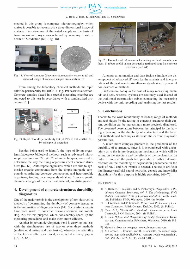
One of the major trends in the development of non-destructivemethods of determining the durability of concrete structuresis the automation of diagnostic tests [64]. Successful attemptshave been made to construct various scanners and robots(Fig. 20) for this purpose, which considerably speed up themeasuring procedures and make them more efficient.
Another important development trend is carrying out testswith the simultaneous use of two or even three methods(multi-modal testing and data fusion), whereby the reliabilityof the tests results is increased, as reported in many papers[18, 35, 65].
Fig. 20. Examples of: a) scanners for testing vertical concrete sur-faces, b) robots useful in non-destructive testing of large flat concrete
elements (Ref. 64)
Attempts at automation and data fusion stimulate the de-velopment of advanced IT tools for the analysis and interpre-tation of the test results simultaneously obtained by severalnon-destructive methods.
Furthermore, today in the case of many measuring meth-ods and sets, wireless systems are routinely used instead ofthe traditional transmission cables connecting the measuringdevice with the unit recording and analysing the test results.
5. Conclusions
Thanks to the wide (continually extended) range of methodsand techniques for the testing of concrete structures their cur-rent condition can be increasingly more precisely diagnosed.The presented correlations between the principal factors hav-ing a bearing on the durability of a structure and the basictest methods and techniques illustrate the current diagnosticpossibilities.
A much more complex problem is the prediction of thedurability of a structure, since it is encumbered with uncer-tainty as to the future degradation mechanisms which will beacting on the structure and the effects of the mechanisms. Inorder to improve the predictive procedures further intensiveresearch on the modelling of degradation phenomena on thebasis of NDT and SDT results is needed. The use of artificialintelligence (artificial neural networks, genetic and imperialistalgorithms) for this purpose is highly promising [66–70].
REFERENCES
[1] Ł. Drobiec, R. Jasiński, and A. Piekarczyk, Diagnostics of Re-
inforced Concrete Structures, vol. 1. The Methodology, Field
Studies, Laboratory Tests of Concrete and Steel, Polish Scien-tific Publishers PWN, Warszawa, 2010, (in Polish).
[2] L. Czarnecki and P. Emmons, Repair and Protection of Con-
crete Structures, Polish Cement, Kraków, 2002, (in Polish).[3] Concrete by PN-EN 206-1 standard – Commentary, ed. Lech
Czarnecki, PKN, Kraków, 2004. (in Polish).[4] J. Bień, Defects and Diagnostics of Bridge Structures, Trans-
port and Communication Publishers, Warszawa, 2010, (in Pol-ish).
[5] Materials from the webpage: www.olympus-ims.com.[6] A. Garbacz, L. Courard, and B. Bissonnette, “A surface engi-
neering approach applicable to concrete repair engineering”,Bull. Pol. Ac.: Tech. 61 (1), 73–84 (2013).
94 Bull. Pol. Ac.: Tech. 63(1) 2015
Non-destructive and semi-destructive diagnostics of concrete structures in assessment of their durability
[7] P. Santos and E. Julio, “A state-of-the-art review on rough-ness quantification methods for concrete surfaces”, Construc-
tion and Building Materials 38, 912–923 (2013).[8] T. Mathia, P. Pawlus, and M. Wieczorowski, “Recent trends in
surface metrology”, Wear 271, 494–508 (2011).[9] M. Siewczyńska, “Method for determining the parameters of
surface roughness by usage of a 3D scanner”, Archives of Civil
and Mechanical Engineering 12 (1), 83–89 (2012).[10] R. Deltombe, K. Kubiak, and M. Bigerelle, “How to select the
most relevant 3D roughness parameters of a surface”, Scanning
36 (1), 150–160 (2014).[11] ISO 25178: Geometric Product Specifications (GPS) – Surface
Texture: Areal (2011).[12] L. Runkiewicz, Testing of Concrete Structures, Gamma Office,
Warszawa, 2002, (in Polish).[13] J. Bungey, S. Millard, and M. Gratham, Testing of Concrete in
Structures, Taylor & Francis, London, 2006.[14] B. Goszczyńska, G. Świt, W. Trąmpczyński, A. Krampikows-
ka, J. Tworzewska, and P. Tworzewski, “Experimental vali-dation of concrete crack initiation and location with acousticemission method”, Archives of Civil and Mechanical Engineer-
ing 12 (1), 23–28 (2012).[15] A. Lewińska-Romicka, Non-destructive Testing, WNT, Warsza-
wa, 2001, (in Polish).[16] B.Goszczyńska, “Analysis of the process of crack initiation and
evolution in concrete with acoustic emission testing”, Archives
of Civil and Mechanical Engineering 14 (1), 134–143 (2014).[17] V. Malhorta and N. Carino, Handbook on Non-destructive Test-
ing of Concrete, CRC Press, London, 2003.[18] J. Hoła, Ł. Sadowski, and K. Schabowicz, “Non-destructive
identification of delaminations in concrete floor toppings withacoustic methods”, Automation in Construction 20 (7), 799–807 (2011).
[19] A. Davis, “The non-destructive impulse response test in NorthAmerica: 1985–2001”, NDT&E Int. 36 (2003).
[20] ASTM C1740. Standard Practice for Evaluating the Condi-
tion of Concrete Plates Using the Impulse-Response Method
(2010).[21] American Concrete Institute Report 228.2R-98, Non-
destructive Test Methods for Evaluation of Concrete in Struc-
tures, ACI, Farmington Hills, 1998.[22] M. Sansalone and W. Streett, Impact-echo: Non-destructive
Evaluation of Concrete and Masonry, Bullbrier Press, Ithaca,1997.
[23] J. Hoła and K. Schabowicz, “State-of-the-art non-destructivemethods for diagnostic testing of building structures - antici-pated development trends”, Archives of Civil and Mechanical
Engineering 10 (3), 5–18 (2010).[24] K. Schabowicz, “Methodology for non-destructive identifica-
tion of thickness of unilaterally accessible concrete elementsby means of state-of-the-art acoustic techniques”, J. Civil En-
gineering and Management 19 (3), 325–334 (2013).[25] K. Schabowicz, “Ultrasonic tomography – the latest non-
destructive technique for testing concrete members – descrip-tion, test methodology, application example”, Archives of Civil
and Mechanical Engineering, 14 (2), 295–303 (2014).[26] K. Schabowicz and V. Suvorov, “Non-destructive testing and
constructing profiles of back walls by means of ultrasonic to-mography”, Russian J. Non-destructive Testing 50 (2), 109–119(2014).
[27] K. Schabowicz, “Modern acoustic techniques for testing con-crete structures accessible from one side only”, Archives of
Civil and Mechanical Engineering,DOI: http://dx.doi.org/10.1016/j.acme.2014.10.001 (2014).
[28] J. Hoła and K. Schabowicz, “Non-destructive elastic-wave testsof foundation slab in office building”, Materials Transactions
53 (2), 296–302 (2012).[29] L. Runkiewicz, Radiography of Building Structures, ITB,
Warszawa, 1980, (in Polish).[30] B. Conyers and D. Goodman, Ground-Penetrating Radar, Al-
taMira Press, Walnut Creek, 1997.[31] C. Andrade and C. Alonso, “Test methods for on-site corro-
sion rate measurement of steel reinforcement in concrete bymeans of the polarization resistance method”, Materials and
Structures 37, 623–643 (2004).[32] K. Gowers and S. Millard, “Measurement of concrete resis-
tivity for assessment corrosion severity of steel using Wennertechnique”, ACI Materials J. 96 (5), 536–541 (1999).
[33] U. Angst and B. Elsener, “On the applicability of the Wennermethod for resistivity measurements of concrete”, ACI Mate-
rials J. 111, 1–6 (2014).[34] A. Garzon, J. Sanchez, C. Andrade, N. Rebolledo, E.
Menendez, and J. Fullea, “Modification of four point methodto measure the concrete electrical resistivity in presence of re-inforcing bars”, Cement and Concrete Composites 53, 249–257(2014).
[35] L. Sadowski, “Non-destructive investigation of corrosion cur-rent density in steel reinforced concrete by artificial neuralnetworks”, Archives of Civil and Mechanical Engineering 13(1), 104–111 (2013).
[36] L. Sadowski, “New non-destructive method for linear polarisa-tion resistance corrosion rate measurement”, Archives of Civil
and Mechanical Engineering 10 (2), 109–116 (2010).[37] L. Sadowski, “Methodology for assessing the probability of
corrosion in concrete structures on the basis of half-cell po-tential and concrete resistivity measurements”, The Scientific
World J., Article ID 714501, 8 (2013).[38] P. Mix, Introduction to Non-destructive Testing: a Training
Guide, John Wiley & Sons, London, 2005.[39] Materials from webpage: www.faro.com.[40] ITB 210 – Instructions for use Schmidt Hammer for Non-
destructive Quality Control of Concrete – No. 210/1977, ITB,Warszawa, 1977, (in Polish).
[41] T. Mathia and B. Lamy, “Sclerometric characterization of near-ly brittle materials”, Wear 108 (4), 385–399 (1986).
[42] H. Nowak, The Use of Thermal Imaging Studies in Construc-
tion, Wroclaw University of Technology Publishing House,Wrocław, 2012, (in Polish).
[43] J. Zwolski and J. Bień, “Modal analysis of bridge structuresby means of Forced Vibration Tests”, J. Civil Engineering and
Management 17 (4), 590–599 (2011).[44] A. Bickley “Pullout testing of concrete”, Concrete Construc-
tion 26 (7), 577–582 (1986).[45] ASTM C 900: Standard Method for Pullout Strength of Hard-
ened Concrete (1982).[46] Materials from webpage: www.viateco.pl.[47] G. Verbeck, Field and Laboratory Studies of the Sulphate Re-
sistance of Concrete, Portland Cement Association, Researchand Development Laboratories, Portland, 1967.
[48] ASTM C1202: Standard Test Method for Electrical Indica-
tion of Concrete’s Ability to Resist Chloride Ion Penetration
(2010).[49] ASTM C 803: Penetration Resistance of Hardened Con-
crete.
Bull. Pol. Ac.: Tech. 63(1) 2015 95
J. Hoła, J. Bień, Ł. Sadowski, and K. Schabowicz
[50] V. Malhotra, Preliminary Evaluation of Windsor Probe Equip-
ment for Estimating the Compressive Strength of Concrete,Mines Branch Investigation Rep. IR 71-1, Ottawa, 1970.
[51] K. Nasser and A. Al-Manaseer, “New non-destructive test forremoval of concrete forms”, Concrete International 9 (1), 41(1987).
[52] J. Monteiro, F. Morrison, and W. Frangos, “Non-destructivemeasurement of corrosion state reinforcing steel in concrete”,ACI Materials J. 95 (6), 704–709 (1998).
[53] A. Zybura, M. Jasniok, and T. Jaśniok, Diagnostics of Rein-
forced Concrete Structures, Vol. 2, Corrosion of Reinforcement
and Protective Properties of Concrete, Polish Scientific Pub-lishers PWN, Warszawa, 2010, (in Polish).
[54] J. Grubb, H. Limaye, and A. Kakade, “Testing pH of concrete,”Concrete International 29 (4), 78–83 (2007).
[55] Materials from webpage: www.agriculturesolutions.com.[56] J. Jasieńko, M. Moczko, A. Moczko, and R. Dżugaj, “Test-
ing the mechanical and physical properties of concrete in thebottom perimeter ring of the dome of the Centennial Hall inWrocław”, Restoration News 27, 21–34 (2010), (in Polish).
[57] Materials from webpage: www.germann.org.[58] L. Czarnecki and P. Woyciechowski, “Prediction of the rein-
forced concrete structure durability under the risk of carboniza-tion and chloride aggression”, Bull. Pol. Ac.: Tech. 61 (1),173–181 (2013).
[59] B. Zyska, Disasters, Crashes and Microbiological Hazards
in Industry and Construction, Łódź University of Technolo-gy Publishing House, Łódź, 2001, (in Polish).
[60] S. Lu, E. Landis, and D. Keane, “X-ray microtomographicstudies of pore structure and permeability in Portland cementconcrete”, Materials and Structures 39, 611–620 (2006).
[61] G. Wieczorek, Corrosion of Reinforcement Initiated by Chlo-
rides or Carbonation, Lower Silesia Educational Publishers,
Wrocław, 2002, (in Polish).[62] T. Vogel and K. Schellenberg, “Design for inspection of con-
crete bridges”, Materials and Corrosion 63 (12), 1102–1113(2012).
[63] M. Książek, “The biocorrosion of city sewer collector impreg-nated special polymer sulfur binder – Polymerized sulfur ap-plied as the industrial waste material”, Construction and Build-
ing Materials 68, 558–564 (2014).[64] Materials from webpage: www.bam.de.[65] T. Gorzelańczyk, J. Hoła, Ł. Sadowski, and K. Schabow-
icz, “Methodology of non-destructive identification of defec-tive concrete zones in unilaterally accessible massive mem-bers”, J. Civil Engineering and Management 19 (6), 775–786(2013).
[66] J. Bień and P. Rawa, “Hybrid knowledge representation inBMS”, Archives of Civil and Mechanical Engineering 4 (1),41–55 (2004).
[67] L. Gołaski, B. Goszczyńska, G. Świt, and W. Trąmpczyński,“System for the global monitoring and evaluation of damageprocesses developing within concrete structures under serviceload”, Baltic J. Road and Bridge Engineering 7 (4), 237–245(2012).
[68] J. Hoła and K. Schabowicz, “Methodology of neural identi-fication of strength of concrete”, ACI Materials J. 102 (6),459–464 (2005).
[69] Ł. Sadowski and J. Hoła, “New nondestructive way of identify-ing the values of pull-off adhesion between concrete layers infloors”, J. Civil Engineering and Management 20 (4), 561–569(2014).
[70] L. Sadowski and M. Nikoo, “Corrosion current density pre-diction in reinforced concrete by imperialist competitive algo-rithm”, Neural Computing and Applications 25 (7–8), 1627–1638 (2014).
96 Bull. Pol. Ac.: Tech. 63(1) 2015