new approach for determining permeability of hot mix asphalt
TRANSCRIPT

WPI
New Approach for Determining Permeability of
Hot Mix Asphalt
Worcester Polytechnic Institute (WPI)
University of Massachusetts at Dartmouth
WPI
Topics
FLaboratory permeability
FUse of a different approach
FField permeameter
FRecommendations

WPI
Why the concern?
0
10
20
30
40
50
60
70
80
90
100
0 0.2 0.4 0.6 0.8 1 1.2 1.4 1.6 1.8 2 2.2 2.4 2.6 2.8 3 3.2 3.4 3.6 3.8 4
Sieve Size
Per
cen
t P
assi
ng
0.075 0.15 0.3 0.6 1.18 2.36 4.75 9.5 12.5 19
0
10
20
30
40
50
60
70
80
90
100
0 0.2 0.4 0.6 0.8 1 1.2 1.4 1.6 1.8 2 2.2 2.4 2.6 2.8 3 3.2 3.4 3.6 3.8 4 4.2 4.4 4.6
Sieve Size
Per
cent
Pas
sing
0.075 0.15 0.3 0.6 1.18 2.36 4.75 9.5 12.5 19 25
More interconnectedvoids in coarse graded mixes

WPI
Objective
FDetermine a test procedure for evaluation of permeability of HMA

WPI
Use of Laboratory Permeability Test
FFalling Head Permeameter used
FSamples saturated before testing
FCoefficient of permeability is determined, assuming Darcy’s law is valid

WPI
Main Objectives of Mix Design
FWhat do we actually want to know?– Is the pavement going to let in too much
water?
FAt the construction air voids, is the pavement going to let in too much water?
FFor the gradation I have, what is the desirable construction air voids such that the pavement does not let in too much water?

WPI
Approach
FDetermine the amount of interconnected air voids present in the mix
F Interconnected air voids are actually water accessible air voids
FDetermine the amount of water accessible air voids in an accelerated fashion.

WPI
Concept of Porosity
FPorosity is defined as F the % air void in the compacted sample
that is accessible to water. FA sample is vacuum sealed inside a bag
and a density, ρ1 is calculated by using the method outlined in ASTM T130-01.
FThe same sample while under water is opened and a second density, ρ2 is determined.

WPI
Concept of Porosity
F% Porosity =
Fρ1= the vacuum sealed density of compacted sample
Fρ2= density of the vacuum sealed sample after opening under water
X100?2
?1?2%P
−=
WPI
Permeability and Porosity
FWater flows through accessible voids or pore spaces in a pavement.
FHence, the rate of flow must be related to the amount of water accessible voids, or porosity, in some way.
FTherefore, the permeability or coefficient of permeability must be a function of porosity.

WPI
y = 2E-05e0.5417x
R2 = 0.55
y = 3.66E-05e0.44x
R2 = 0.80
0.0000.0010.0020.0030.0040.0050.0060.0070.0080.0090.0100.0110.0120.0130.0140.0150.0160.0170.0180.0190.0200.0210.0220.0230.0240.0250.0260.0270.028
0 1 2 3 4 5 6 7 8 9 10 11 12 13 14 15
Porosity, VTM, %
Co
effi
cien
t o
f P
erm
eab
ility
, cm
/s
VTM SSD Porosity Expon. (VTM SSD) Expon. (Porosity)
9.5 mm and 12.5 mm NMAS

WPI
Interpretation of data
FThe critical porosity corresponding to a critical permeability can be determined.
FAs recommended by Florida DOT researchers, considering a critical permeability of 10-3 cm/second,
- a critical porosity of 7 percent is determined.

WPI
Interpretation of Data
FTherefore, mix design samples can be checked for permeability potential
F by conducting porosity tests on samples compacted to construction voids (as determined by SSD method),
Fand a maximum allowable porosity value of 7 percent can be used.

WPI
Can we get an indication of porosity before we start?
FPorosity has been defined as total amount of water accessible voids in a mix.
FHow can one estimate the porosity from knowledge of mix gradation and air voids?
FMultiple regression analysis conducted with porosity, air voids and aggregate gradation data.

WPI
683
.897
.804
.7981.406
CountNum. Missing
|R|R Squared
Adjusted R SquaredRMS Residual
Regression SummaryPorosity vs. 2 IndependentsRow exclusion: perm #1_12.5_9.5.svd
2 526.694 263.347 133.281 <.0001
65 128.432 1.976
67 655.126
DF Sum of Squares Mean Square F-Value P-ValueRegression
Residual
Total
ANOVA TablePorosity vs. 2 IndependentsRow exclusion: perm #1_12.5_9.5.svd
3.472 1.225 3.472 2.834 .00611.260 .080 .861 15.686 <.0001
-.127 .028 -.251 -4.575 <.0001
Coefficient Std. Error Std. Coeff. t-Value P-Value
InterceptAir Voids, SSD
PP2.36
Regression CoefficientsPorosity vs. 2 IndependentsRow exclusion: perm #1_12.5_9.5.svd
-4
-3
-2
-1
0
1
2
3
4
Res
idua
l Por
osity
2 4 6 8 10 12 14 16Fitted Porosity
Residuals vs. FittedRow exclusion: perm #1_12.5_9.5.svd
Porosity = 3.47 + 12.6 * VTM – 0.127 * PP 2.36

WPI
0
1
2
3
4
5
6
7
8
9
10
11
12
13
14
0 1 2 3 4 5 6 7 8 9 10 11 12
Voids in Total Mix, %
Po
rosi
ty, %
25 PP 2.36 30 PP 2.36 35 PP 2.36 40 PP 2.36 45 PP 2.36

WPI
Critial air voids for mixes with different gradationsPercent passing the 2.36 mm sieve Critical Air Voids
25 530 635 6.540 745 7.5

WPI
Note
– For a mix with approximately 45 percent passing the 2.36 mm sieve
– A porosity of 7 percent corresponds to VTM of 7 percent
– Most of experiences from the past (in the pre-Superpave era) has been with mixes with 40-45 percent passing the 2.36 mm sieve

WPI
Note
– A density of 93 percent of TMD or VTM of 7 percent has often been recommended and used, without any significant permeability problem.
– Therefore, the selection of 7 percent porosity as a critical porosity seems to be justified.

WPI
0
1
2
3
4
5
6
7
8
9
10
11
20 25 30 35 40 45 50
Percent Passing the 2.36 mm Sieve
Po
rosi
ty, %
5 % VTM 6 % VTM 7 % VTM 8 % VTM

WPI
List of critical percent passing the 2.36 mm sieve for specific air voidsAir Voids Allowable percent
passing the 2.36 mm sieve5 > 256 > 317 > 418 > 45

WPI
Permeability or Porosity?
FWhich parameter should be used during mix design to prevent mixes from being excessively permeable –
F Is it permeability test or is it porosity test?
FMeasuring permeability is a more direct approach.
FPorosity shows a very good relationship with permeability

WPI
Permeability or Porosity?
FPorosity is a good mix design parameter candidate
FArgument becomes stronger when one considers the coefficient of variation of the permeability and the porosity tests.
FThe average CV for permeability testing is about three times the average CV of porosity.

WPI
Permeability or Porosity?
FHence, as a regular test procedure, because of better repeatability,
FPorosity seems to be more appropriate than permeability.

WPI
What about field permeability?
FCan we use it as a quality control tool?
FCan we use it for getting a true picture of flow through porous media?
FCan we use it to determine permeability in different directions?

WPI
Field Permeameter
14 cm19.0 cm
16 cm
1.5 cm
PlexiglasStandpipes(3 tiers)
19.0 cm
3.0 cm
2.0 cmFlexibleBase
Plastic Base to holdweights
Plastic base to holdstandpipes
8.9 cm hole
3.8 cm
8.9 cm

WPI
Field Testing
15 cm 15 cm
Testing for eachlocation
Core fromeachlocation

PressurizedMembraneon side ofsample
Head of water
Top layer
New Field Permeameter

New Permeameter
FSame equipment for lab and field test
FBasically falling head or constant head test
FCuts down variability of results from using different equipment in lab and field

PROTOTYPE
Mobile Cart F LaptopF On-board water
pressure tank (20 gal, 30 psi precharge)
F Core rigF Valve assemblyF Permeameter in
foreground

NEW PERMEAMETER
GeneralF Laptop PCMCIA data
acquisitionF Differential/gauge
pressure for head pressure, LVDT for volume change
FieldF 4” ID, 5” OD ring
cored 3” Deep (100mm x 63.5mm)
LabF 6” diameter by 4”
tall specimen (150mm x 100mm)
PROPOSED PROCEDURE (Field)
F Core & remove a ½” ring 3” deepF Set permeameter in grooveF Saturate, charge actuator, & apply confining
pressure equal to or higher than max head pressure to be applied
F Start data acquisitionF Open valve to apply head pressureF Stop data acquisition when actuator is full
downF Bleed pressures, remove permeameter &
patch “moat”
PROPOSED PROCEDURE (Lab)
FSame as field except without the coring and patching
FTest will need to be done over a floor or sink drain
FConfining cell for lab is interchangeable with smaller field cell via quick disconnects

4” CORE BARREL INSIDE 5” CORE BARREL
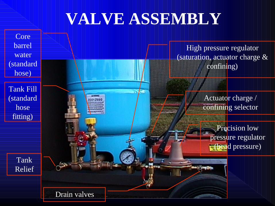
VALVE ASSEMBLY
Tank Relief
Tank Fill (standard
hose fitting)
Core barrel water
(standard hose)
High pressure regulator (saturation, actuator charge &
confining)
Actuator charge / confining selector
Precision low pressure regulator
(head pressure)
Drain valves

PERMEAMETER ASSEMBLY
F Upper box assembly has electronics, actuator, and LVDT
F Lower permeameter cell

TOP VIEW OF PERMEAMETER ASSEMBLY

WPI
Recommendations
FUse porosity as an indicator of mix permeability
FEstimate porosity and use estimated porosity to select gradation or desirable construction air voids
FConduct porosity test on mix design samples at construction air voids

WPI
Comments
Questions
Suggestions