procedure for determining permeability of rock core ... usbr 6310-09 procedure for determining...
TRANSCRIPT

Designation USBR 6310-09
Procedure for Determining Permeability of Rock Core — Flow Pump Permeability
Test
This procedure is under the jurisdiction of the Materials Engineering and Research Laboratory, code 86-68180, Technical Service Center, Denver, Colorado. The procedure is issued under the fixed designation USBR 6310. The number immediately following the designation indicates the first year of acceptance or the year of last revision. 1.Scope 1.1 Explanation.-This designation establishes the guidelines, requirements, and procedure for determining permeability of rock specimens using a flow pump permeability test. 1.2 Context.-This designation is described in the context of obtaining data for designing, constructing, or maintaining Reclamation structures. 1.3 Application.-This designation applies to intact hard and soft rock test specimens. 1.4 Units.-The values stated in SI/metric (inch-pound) units are to be regarded as standard. 1.5 Caveats.-This designation does not purport to address all the safety issues associated with its use, and may involve use of hazardous materials, equipment, and operations. The user has the responsibility to establish and adopt appropriate safety and health practices. Also, the user must comply with prevalent regulatory codes while using this procedure.
1.6 Sources.-This designation reflects the information available from ASTM and Reclamation (see section 2). 2.Applicable Documents 2.1USBR Procedures: USBR 1008Calibrating Linear
Variable Differential Transformers
USBR 1012 Calibrating Balances or
Scales USBR 1050 Calibrating Pressure
Transducers USBR 1055 Calibrating Differential
Pressure Transducers USBR 1450 Calibrating Triaxial-
Type Chambers for Pressure-Volume Change Relations
USBR 3000 Using Significant Digits
in Calculating and Reporting Laboratory Data

USBR 6258-09
2
USBR 3910 Standard Terms and Symbols Relating to Rock Mechanics
USBR 5300 Determining Moisture
Content of Soil and Rock by the Oven Method
USBR 5750 Performing
Consolidation-Undrained Triaxial Shear Testing of Soils
USBR 6010 Handling, Storage,
Shipment, Inspection and Photographing of Rock Core
USBR 6020 Preparing Rock
Specimens for Laboratory Compression Testing
USBR 9300 Procedure for Checking,
Rounding, and Reporting of Laboratory Data
2.2ASTM Documents: ASTM D 4525Test Method for
Permeability of Rock by Flowing Air
3.Summary of Method A carefully prepared rock specimen, enclosed in a membrane, is placed in a triaxial test chamber and back pressure saturated. The rock specimen is then subjected to a given flow rate of water. By measuring the pressure differential across the specimen (upstream and downstream from the specimen) the pressure gradient is determined and the
coefficient of permeability of the rock specimen is calculated. 4.Significance and Use The permeability of rock is an important property that is used for the classification of rock and in the design of structures in, on, or with rock. This test method is designed to measure the permeability of rock that have permeabilities as low as 1 x 10⁻⁸ cm/s (0.001 foot/year) and aid projects in which low permeability coefficients need to be quantitatively determined. Permeability tests using the flow pump permeability technique can be performed under a low gradient (i < 5). Flow pump permeability testing can accurately obtain permeability coefficients more quickly (in minutes and hours) than conventional permeability testing techniques, such as constant head and falling head (in weeks). Note 1.-Because flow pump permeability tests can be performed in a short time compared to constant head or falling head tests, they enhance laboratory productivity. 5.Description of Terms Specific to This Designation 5.1 Back Pressure.-A water pressure (generally 0.55 MPa [80 lbf/in2]) applied to the specimen to fully saturate it.
5.2 Permeability.-The capacity of a
porous or fractured rock to conduct liquid or gas (usually water); also called hydraulic conductivity.

USBR 6310-09
3
5.3 Equivalent Permeability.-The permeability of a rock mass, assuming that the rock mass can be represented as one uniform and porous medium over the entire test interval. 5.4 Other Terms.-See USBR 3910. 6.Apparatus 6.1 General.-Reclamation's flow pump permeability system, shown on figures 1, 2, and 3, consists of (a) a triaxial test chamber, (b) pressure transducers, (c) one differential pressure transducer, (d) one LVDT (linear variable differential transformer), (e) one high-pressure syringe flow pump with custom stainless steel syringe, (f) a desktop computer with printer, and (g) a data acquisition system.
Figure 1. - Flow pump permeability system: (a) triaxial test chamber, flow pump, and drain and volume tubes, (b) data acquisition system, and (c) desktop computer and printer.
Figure 2. - Triaxial shear test chamber with drain tubes, volume tube, and pressure transducer for flow pump permeability system.
Figure 3. - Schematic of flow pump permeability system: (a) driving system, (b) stainless steel syringe, and (c) differential pressure transducer. 6.2 Balance or Scale.-Balance or scale meeting the requirements shown in table 1.

USBR 6258-09
4
Table 1.- Balance or scale requirements.
Test Specimen Size
Balance or Scale
Diameter mm (in)
Height mm (in)
Capacity in grams
Readability in grams
50.8 (2.0) 127.0 (5.0)
1,000 00.05
71.1 (2.8) 177.8 (7.0)
2,000 0.10
152.4 (6.0)
381.0 (15.0)
25,000 10
228.6 (9.0)
571.5 (22.5)
75,000 10
6.3 Timer.-A timing device indicating elapsed time to the nearest 1 second. 6.4 Specimen Size Measurement Devices.-Devices used to measure the height and diameter of the specimen. The devices must be capable of measuring to the nearest 0.01 mm (0.0001 in) and should be constructed such that their use will not disturb the specimen. A vernier caliper is recommended for measuring specimen height and a pi tape for measuring specimen diameter. 6.5 Water Container.-Of sufficient size to accommodate the test specimen. 6.6 Suspension Wire and Specimen Carriage.-For suspending the specimen to determine its mass in air and water. 6.7 Triaxial Test Chamber Pressure Maintaining and Measurement Devices.-Devices must be capable of applying and controlling the triaxial test chamber
pressure to within ±0.0035 MPa (±0.5 lbf/in2). 6.8 Triaxial Test Chamber.-A 150-mm (6-in) diameter cylindrical stainless steel chamber with a top cap, piston, top plate, and retainer bar with drain tubes for applying back pressure, and a volume tube for applying lateral pressure (see figure 2). The back pressure and lateral pressure transducers are mounted on the back pressure and lateral pressure tube lines. In this triaxial test chamber, a cylindrical specimen, enclosed by a membrane sealed to end plates, is placed and subjected to a permeability test under a back pressure while confined by a designated lateral pressure. 6.9 Specimen End Plates.-The end plates must be constructed of a noncorrosive impermeable material such as aluminum, stainless steel, or titanium; each must have a circular cross section and circular plane surface of contact with the specimen. The diameter of the end plates should be within ±0.5 millimeter (0.020 in) of the diameter of the specimen. The bottom end plate must be coupled to the triaxial test chamber bottom plate to prevent lateral motion or tilting. The top end plate must be designed to receive the piston so that the piston-to-end plate contact area is concentric with the cap. The top end plate should be constructed in a manner so that piston play or "wobble" is restricted to 4 degrees or less perpendicular to the top end plate. Each end plate must be plumbed so air can be flushed from the end plate. The cylindrical surface of the end plates to which the

USBR 6310-09
5
membrane is sealed should be smooth and free of scratches. The end plates must be constructed so that pore pressure measurements can be obtained from both ends of the specimen. Each end plate shall be fitted with a porous insert. 6.10 Porous End Plate Inserts.-Porous inserts are manufactured from silicon carbide, aluminum oxide, sintered bronze, or ceramic. The material must not be susceptible to corrosion by rock substances or moisture. The proper coarseness of insert depends upon the type of test being performed and the rock being tested. The insert should be coarse enough to develop adequate interlock with the specimen, but fine enough to prevent excessive intrusion of rock particles into the pores of the insert. 6.11 Pore Pressure Transducers.-Pore pressure transducers are used to measure the back pressure in the rock specimen. The pressure transducers shall have an accuracy of ±0.25 percent over their full range. The transducer is shown on figure 2 and can withstand pressures up to 1.72 MPa (250 lbf/in2). 6.12 Lateral Pressure Transducer.-The lateral pressure transducer is used to measure the lateral pressure applied inside the triaxial test chamber. The transducer shall have an accuracy of ±0.25 percent over its full range. The transducer is shown on figure 2 and can withstand pressures up to 1.72 MPa (250 lbf/in2). 6.13Differential Pressure Transducer.-A standard pressure transducer with a range of 0.034 to
0.069 MPa (5 to 10 lbf/in2) and a precision of 0.0002 MPa (0.025 lbf/in2) (see figure 3) is used to conduct the test. The differential pressure transducer is used to measure pressure changes during the test. 6.14 Volume Tube.-A constant bore glass tube supported by a sectional brass pipe with watertight seals on both ends. The volume tube is used primarily to visually monitor the pressure change in the specimen, and to create lateral pressure on the specimen. It also serves as a water reservoir and flushing tube when de-airing the system. The volume tube must be able to withstand pressures up to 1.724 MPa (250 lbf/in2). The volume tube assembly must be enclosed in a 6-mm (3-in) thick Plexiglas shield to prevent injury to personnel if the volume tube fails. 6.15 Drain Tubes.-Constant bore glass tubes supported by a sectional brass pipe with watertight seals on both ends. The drain tubes are used as a water reservoir and flushing tube when de-airing the system, and for creating back pressure on the specimen, and may be used to monitor the volume of fluid drainage during the test. The drain tubes must be capable of withstanding pressures up to 1.724 MPa (250 lbf/in2). Each drain tube assembly must be enclosed in a 6-mm (3-in) thick Plexiglas shield to prevent injury to personnel if the drain tube fails. 6.16 Flushing Tank Constant Bore.-Plexiglas tubes used for flushing air from the triaxial assembly with a water-tight seal on one end.

USBR 6258-09
6
One tank is mounted on the differential pressure transducer and one tank is mounted on each of the exit ports of the top and bottom end plates. 6.17 Specimen Membrane.-A membrane used to encase the specimen to isolate it from the triaxial test chamber fluid. Membranes should be carefully inspected prior to use. The membrane should be replaced if any flaws or pinholes are evident. To minimize restraint to the specimen, the unstretched membrane diameter should be between 75 percent to 90 percent of the specimen diameter. The membrane thickness must not exceed 1 percent of the diameter of the specimen. The membrane must be sealed to the end plates with two rubber O-rings. These O-rings must have an unstressed inside diameter of 75 percent or less of the diameter of the end plate. 6.18 Linear Variable Differential Transducer (LVDT).-A single LVDT with a sensitivity of 0.01 mm (0.0001 in) and a total travel of 40.6 mm (1.6 in) is used to measure the change in the length of the rock specimen during the test. 6.19 High Pressure Syringe Flow Pump.-A commercially available single syringe infusion/withdrawal pump (figure 3) is used for the pump drive mechanism. The pump consists of a synchronous electric motor with speed reproducibility of 0.5 percent. The motor is attached through a gearbox to a worm gear that drives the syringe piston. The gearbox has a selection knob for 12 discrete speeds
from 63.5 mm/min (2.5 in/min) to 0.0125 mm/min (0.0005 in/min). The speed for each setting is given in table 2. The syringe piston is pushed by a solid saddle that rides on the worm gear. The travel length of the saddle is 300 mm (12 in). 6.20 Stainless Steel Syringe.-A syringe is built from a solid stainless steel block 38 mm (1.5 in) square in with a 16-mm (0.625 in) diameter hole, leaving a thick wall and minimizing the volume of fluid required to fill the syringe. The syringe has a bleed port so that the system can be flushed easily and the entrapped air can be removed. The syringe piston is made of a solid stainless steel polished rod 12.5 mm (0.5 in) in diameter. The fluid flow rates (see column 3 of table 2) can be controlled by adjusting the speed of injection (see column 2, table 2). Table 2. - Flow pump driving mechanism speeds and flow rates.
Worm Gearbox
Speed Setting (in/min)
(cm3/s)
Flow Rate
cm/min 1 2.56.35 1.347 x
10-1 2 1.02.54 5.398 x
10-2 3 0.51.27 2.694 x
10-2 4 0.250.635 1.347 x
10-2 5 0.1250.318 6.737 x
10-3 6 0.050.127 2.694 x
10-3 7 0.0250.064 1.347 x
10-3 8 0.01250.032 6.737 x
10-4

USBR 6310-09
7
Worm Gearbox
Speed Setting (in/min)
(cm3/s)
Flow Rate
cm/min 9 0.0050.013 2.694 x
10-4 10 0.00250.0064 1.347 x
10-4 11 0.001250.0032 6.737 x
10-5 12 0.00050.0013 2.694 x
10-5 6.22 Data Acquisition System.-Reclamation uses a data acquisition system shown on figure 4. 7.Auxiliary Items
• Micrometer calipers • Hand tools • Photographic camera • Centering rod • Retainer bar • Stopwatch • Rubber membranes and
membrane expander • O-rings and O-ring expander • Compressed air • Vacuum pump • Hoses, tubes, multiport
manifold, and valves • Potable water free of dissolved
oxygen, acids, alkalis, and oils • Feeler gage
8.Calibration and Standardization 8.1 Pressure Transducers.-Calibrate pressure transducers in accordance with USBR 1050. 8.2 Differential Pressure Transducer.-Calibrate differential pressure transducer in accordance with USBR 1055.
8.3 LVDT.-Calibrate LVDT using USBR 1008. 8.4 Triaxial Test Chamber.-Calibrate the triaxial test chamber in accordance with USBR 1450. 8.5 Permeability Test Equipment.-Permeability apparatus including flow pump and syringe must be recalibrated after 10 permeability tests have been performed or once every 2 years, whichever occurs first according to manufacturer’s recommendations. 9.Test Specimens 9.1 Minimize Mechanical Damage.-Care is exercised in core drilling, handling, sawing, grinding, and lapping the test specimens to minimize the mechanical damage caused by stress and heat. The test specimens are to be prepared using the procedure contained in USBR 6020. It is recommended that liquids other than water be prevented from contacting the test specimens. The end surface areas of the specimens shall be sufficiently planed that a 0.025 mm (0.001 in) feeler gage will not pass under a straightedge placed on the surfaces of the bearing plates. The two opposite end surfaces shall be parallel to within 0.005 mm/mm (0.005 in/in) of lateral dimension. 9.2 Use Cylinders.-The test specimens shall be right circular cylinders within the tolerances specified in section 9.1.

USBR 6258-09
8
9.3 Ensure Sufficient Size.-The specimen shall have a length-to-diameter ratio (L/D) of 0.8 to 1.25 and a diameter of not less than 50 mm (2 in). Note 2.-The diameter of a rock test specimen is best when it is at least ten times the diameter of its largest mineral grain. For weak rock types which behave more like soil (for example, weakly cemented sandstone), the specimen diameter should be at least six times the maximum particle diameter. The specified minimum specimen diameter of about 50 mm (2 in) is considered satisfactory in most cases. When cores of diameter that are smaller than the specified minimum must be tested (i.e. larger diameter cores are unavailable), make a suitable notation of this in the report. 9.4 Avoid Irregularities.-The sides of the specimen shall be generally smooth and free of abrupt irregularities, with all elements straight to within 0.50 mm (0.020 in) over the full length of the specimen. 10. Conditioning Represent host rock properties, as far as practical, in the rock specimens to be tested. The more accurate the representation, the more meaningful the more parameters for designing, constructing, or maintaining Reclamation structures on, in, or with rock will be. 11. Precautions 11.1 No Alternations.-Rock core specimens used in this test
designation should be handled so that their properties are not altered in any way. 11.2 No Air Pockets.-The system should be thoroughly de-aired so that air pockets should not be present in the flow pump permeability system while the tests are being conducted. 11.3 Avoid Shattering.-Pressure should be slowly applied and released from the triaxial assembly to prevent the glass volume tubes from shattering. 11.4 No Clogged Pores.-Be sure that the porous platens do not have any clogged pores. A reduction in porosity of the platens may give unrepresentative test results. 11.5 No Impurities.-The porous inserts in the end plates should be cleaned frequently to remove any impurities which may inhibit free water flow. 11.6 Safety Equipment.-Safety shoes should be worn when de-airing the equipment or placing the specimen. Safety glasses should be worn when applying air pressure to the volume/drain tubes when saturating the specimen. 11.7 No Spills.-Water spillage in the area should be cleaned up as soon as possible. 12.Preparation of Apparatus 12.1Saturation of Porous Inserts and De-airing of End Plates: 12.1.1If new porous inserts with bubbling pressure greater than 35 kPa

USBR 6310-09
9
(5 lbf/in2) are to be used for the test, then completely submerge the end plate, connecting lines, and porous insert in de-aired water and boil them from 8 to 16 hours to ensure that all entrapped air has been removed. 12.1.2 If new porous inserts with a bubbling pressure of 35 kPa (5 lbf/in2) or less are to be used for the test, then completely submerge the end plates, connecting lines, and porous inserts in de-aired water and boil them for a minimum of 2 hours to ensure that all entrapped air has been removed. 12.1.3 If end plates with previously saturated porous inserts with a bubbling pressure greater than 35 kPa (5 lbf/in2) are to be reused for the test, then remove end plates, connecting lines, and porous inserts from the triaxial assembly, completely submerge them in de-aired water, and boil them for a minimum of 4 hours to remove any entrapped air. 12.1.4 If end plates with previously saturated porous inserts with a bubbling pressure of 35 kPa (5 lbf/in2) or less are to be reused for the test, then these end plates, connecting lines, and porous inserts can be left in the triaxial assembly for subsequent tests and de-aired using vacuum. 12.2 De-airing the Triaxial Test Chamber: 12.2.1 Attach the saturated end plates with porous inserts to the triaxial test chamber bottom plate. 12.2.2 Place the bottom end plate with centering dowel into the
hole in the center of the triaxial test chamber bottom plate. 12.2.3 To ensure that pressure does not build up in the system when the end plate connecting lines are attached to the fittings in the triaxial test chamber bottom plate, open valves to allow a small amount of water to flow from the appropriate drain tube and flushing tank through the fittings in the triaxial test chamber bottom plate while the appropriate end plate connecting lines are being attached. 12.2.4 Attach the bottom end plate connecting lines to the appropriate fittings in the triaxial test chamber bottom plate. Close valves. 12.2.5 Attach the top end plate connecting lines to the appropriate fittings in the triaxial test chamber bottom plate. Close valves. 12.2.6 Place the triaxial test chamber into the groove in the triaxial test chamber bottom plate. 12.2.7 Check that all system valves are closed. 12.2.8 Fill the triaxial test chamber about one-half full with de-aired water. 12.2.9 Open triaxial test chamber cap relief valve. 12.2.10 Set the triaxial test chamber cap in place and force the cap down until it is properly seated on the triaxial test chamber.

USBR 6258-09
10
12.2.11 Insert the piston through the opening in the triaxial test chamber cap until the flange on the piston is resting on top of the triaxial test chamber cap. 12.2.12 Open the valves to the top of the volume and drain tubes. 12.2.13 Attach vacuum hoses to the tops of the volume tube, drain tubes, and the fitting on the triaxial test chamber cap relief valve. 12.2.14 Attach the other ends of the vacuum hoses to a suitable vacuum source, such as a vacuum pump. Turn on the vacuum pump. 12.2.15 Apply a vacuum of about 140 kPa (20 lbf/in2) for 5 minutes. 12.2.16 Release the vacuum to the triaxial test chamber by uncoupling the vacuum line from the vacuum pump multiport manifold. Maintain the vacuum in the volume tube and drain tubes. 12.2.17 Open volume tube drain valve and the volume tube isolation value, and fill the volume tube to the top of its markings with de-aired water from the triaxial test chamber (vacuum is still in the volume tube). 12.2.18 Close volume tube drain valve. 12.2.19 Open drain tube valves and fill the drain tubes to the top of their markings with de-aired water from the triaxial test chamber (vacuum is still in the drain tubes).
12.2.20 Close drain tube valves. 12.2.21 Release the vacuum from the volume and drain tubes by uncoupling the appropriate vacuum lines from the vacuum pump. 12.2.22 Reattach the vacuum hose to the triaxial test chamber cap relief valve to the vacuum source. 12.2.23 Open the volume tube drain valve and allow the water level in the volume tube to drop to about the 635-mm (25-in) level. 12.2.24 Close the volume tube drain valve. 12.2.25 Open drain tube valves and allow the water level in the drain tubes to drop to about the 635-millimeter (25-in) level. 12.2.26 Close drain tube valves. 12.2.27 Reattach vacuum hoses to the tops of the volume tube and drain tubes. 12.2.28 Displace water back and forth between the volume and drain tubes and the triaxial test chamber by repeating subparagraphs 12.2.16 through 12.2.28 until air bubbles cannot be seen in the tubes. 12.2.29 If the volume and drain tubes are not full at the end of the flushing process, fill the tubes by opening valves with vacuum applied to the top of each tube. Fill the volume and drain tubes to the top of their tube markings with de-aired water so they can be drained to the desired level for testing purposes.

USBR 6310-09
11
12.2.30 Close valves. 12.2.31 De-air the flushing tanks and associated lines and fittings. A rubber stopper with a short length of tubing through the hole in the center of the stopper is inserted into the upper end of each flushing tank. 12.2.32 Attach a vacuum hose to each tube. Plug the vacuum hoses attached to the top of the flushing tanks into the vacuum source. 12.2.33 Allow each flushing tank to fill within about 25 mm (1 in) of the top. 12.2.34 Close flushing tank valves. 12.2.35 Release the vacuum from the flushing tanks by uncoupling the appropriate vacuum lines from the vacuum pump. 12.2.36 Plug the vacuum hose to the triaxial test chamber relief valve into the vacuum source. 12.2.37 Open valves and allow the flushing tank water levels to drop to about 25 mm (1 in). Close valves. 12.2.38 Displace water back and forth between the flushing tanks and the triaxial test chamber by repeating subparagraphs 12.2.32 through 12.2.38 until air bubbles cannot be seen in the flushing tank. 12.2.39 Close valves.
12.2.40 Uncouple all vacuum lines from the manifold on the vacuum pump and shut off the vacuum pump. 12.2.40 Uncouple all vacuum lines from the triaxial assembly, coil the vacuum lines, and store in a suitable location for future use. 12.2.41 Do not drain the water from the triaxial test chamber until the end plates and specimen are ready to be placed in the triaxial test chamber as outlined in section 13. 12.3 De-Airing the Pore Pressure Transducers: 12.3.1 With the pressure transducer connecting valves closed, detach the pore pressure transducers from their fittings on the apparatus. Using a syringe, fill each transducer with de-aired water. 12.3.2 Open valve to allow a small amount of water to escape from the triaxial test chamber. With water flowing, attach the transducer for the bottom end plate to the appropriate fitting. Leave the transducer valve open for the rest of the tests. 12.3.3 Open the second valve to allow a small amount of water to escape from the triaxial test chamber. With water flowing, attach the transducer for the top end plate to the appropriate fitting. Leave the valve open. Close the relief valve. 12.4 De-Airing the Differential Pressure Transducer: 12.4.1 Fill the flushing tank on the differential pressure transducer about two-thirds full of de-aired

USBR 6258-09
12
water. Close the volume tube isolation valve to isolate the volume tube and differential pressure transducer from the triaxial test chamber. 12.4.2 Open the valve on the differential pressure transducer. Remove the bottom plate on the differential pressure transducer by unscrewing the four cap head screws which hold it to the body of the transducer. Open valve to fill the bottom plate with de-aired water from the flushing tank. Open valves to the volume tube and allow water to flood over the exposed capsule located under the main body of the differential pressure transducer. With water flowing, place the bottom plate back on the differential pressure transducer while being careful not to entrap air. Close valve to the volume tube, but leave valve to the flushing tank slightly open to relieve any pressure which results from tightening the cap screws. Tighten the four cap head screws. 12.4.3 Flush the differential pressure transducer thoroughly by attaching a hand-held vacuum/ pressure pump to the top of the flushing tank. Open valve to the volume tube and flushing tank and flush the water back and forth several times between the flushing tank and the volume tube through the differential pressure transducer. When this step is complete, be sure the water level in the volume tube is near the full mark, and close the valve to the flushing tank. Open the volume tube isolation valve.
Note 3.-Extreme caution must be used when flushing the differential pressure transducer because a pressure greater than about 70 kPa (10 lbf/in2) can damage the measuring capsule inside the transducer. 13.Procedure 13.1 Using micrometer calipers, measure and record the height and diameter of the specimen to the nearest 0.01 millimeter (0.01 in) at three places (lower, middle, and upper sections of the specimen). Calculate and record the average height, diameter, and cross-sectional area of the test specimen. 13.2 Measure and record the mass of the specimen to the nearest 0.1 gram (0.0001 lb). 13.3 Wipe clean the surface of the rock specimen. Immerse it and the porous platens in tap water for 12 to 15 hours. 13.4 Fill the triaxial test chamber, syringe, drain tubes, and volume tube with de-aired water. 13.5 Using bleed valves and steps in section 12, de-air the triaxial test chamber, drain tubes, volume tube, pressure transducers, and the syringe. 13.6 Carefully drain the triaxial test chamber, leaving ±13 mm (2 in) of de-aired water in the triaxial test chamber. 13.7 After specimen and platen immersion is complete, take them out and wipe them clean with a dry towel. Place the false platens on the top and

USBR 6310-09
13
bottom ends of the rock specimen. Encapsulate the rock specimen and the platens inside a rubber membrane and seal the assembly by placing suitable O-rings over the top and bottom platens. Place the assembly in the triaxial test chamber. 13.8 Using the centering rod, center the assembly into the triaxial test chamber. 13.9 Place the top cap and the top cap plate on the triaxial shear triaxial test chamber. 13.10 Bolt the retainer bar on the triaxial shear test triaxial test chamber. 13.11 Fill the triaxial shear test triaxial test chamber with de-aired water. 13.12 De-air the triaxial test chamber using bleed valves. 13.13 Install the LVDT and take an initial reading. 13.14 Fill the syringe housing, the pore-pressure transducer housing, and the interconnecting tubes with de-aired water. 13.15 Remove trapped air from the system by using the bleed valves. 13.16 Allow 12 to 15 hours for saturation under a back pressure of 0.55 MPa (80 lbf/in2) and a lateral pressure of 0.62 MPa (90 lbf/in2) by applying air pressure on the drain (back pressure) and volume (lateral pressure) tubes.
13.17 Perform Saturation Check: Apply a lateral pressure of 0.62 MPa (90 lbf/in2) and a back pressure of 0.55 MPa (80 lbf/in2), making sure the valve between the specimen and flow pump is closed. Close all other pressure valves except the lateral pressure valve. Connect voltmeters to the two transducers (lateral and back pressure). Close the ball valve and monitor the voltage change. Take the final LVDT reading. If the voltage changes, then check for leaks and ensure that the specimen is fully saturated, as ideally, if no leaks are present and the specimen is fully saturated, the voltage will not change. 13.18 Perform Leakage Check: 13.18.1 Close the valves at the bottoms of the two drain tubes and the volume tube. If no leak occurs, the back pressure transducer and the lateral pressure transducer will show no change. If a leak is detected, trace the source of the leak and correct the situation. 13.18.2 A leak within the triaxial cell cylinder would show up in the form of a pressure increase on the back pressure transducer. This pressure increase would occur if water is leaking from the cell (higher confining pressure) into the specimen (at a lower back pressure). However, a pressure increase recorded by the back pressure transducer may mean that the specimen is still consolidating under the applied effective stress. Therefore, if a pressure increase is observed on the back pressure transducer, the rate of pressure increase should be checked at 15-minute intervals for a total period of one hour. A continual pressure rate

USBR 6258-09
14
increase over a period of two hours would clearly indicate a leakage in the system. If the pressure rate decreases with time as registered by the back pressure transducer, the specimen is still consolidating and the permeability measurement should not be attempted before a steady-state condition is reached. Note 4.-A pressure increase inside the specimen does not necessarily correspond to a voltage increase. A pressure decrease within the specimen suggests that saturation is still taking place. 13.19 Perform Compliance Test This step checks for remaining undissolved air in the system. Close the valve connecting the flow pump and triaxial shear triaxial test chamber. Set the syringe speed to 9 (0.13 mm/min [0.005 in/min]) and start the pump. Wait at least 10 seconds, then close the ball valve while simultaneously monitoring the time (t = 0 is the instant the valve is closed). Read and record the time it takes for the voltmeter reading to reach 50 mV to the nearest 1 minute. Open the valve and repeat the compliance test with a different back pressure. If the system is entirely saturated, the time necessary to attain a 50-mV reading for the two different back pressures should be identical. A ±2-second deviation is usually acceptable given the inaccuracy introduced by opening and closing the ball valve in addition to using a stop watch. If the two compliance times do not fall within this range, the system still contains a substantial amount of air. Repeat the saturation
check and the compliance test until no air is entrapped in the system. 13.20 Select Syringe Speed: Open all valves on the triaxial shear triaxial test chamber except the two outlet valves on the injection and back pressure lines. Set the pump driving mechanism speed at 9 (0.13 mm/min [0.005 in/min]), and switch on the flow pump. Wait at least 10 seconds and then close the ball valve. Simultaneously monitor the voltage, being careful not to exceed a 50-mV voltage differential. If a satisfactory steady voltage change occurs (not exceeding 50 mV), then speed number 9 is acceptable for the experiment. However, if the voltage change is too small (lower than 10 mV) or too large (greater than 50 mv), then adjust the speed of the pump driving mechanism until a satisfactory steady voltage occurs (between 15 and 50 mV). Note 5.-If unfamiliar with the material behavior, a general rule of thumb is to always begin with a very low speed setting and progress with higher speeds until a measurable pressure is obtained. 13.21 Perform Permeability Test: 13.21.1 After selecting an appropriate speed setting, close the ball valve and start the flow pump to inject water into the specimen. Determine the steady-state pressure differential across the rock specimen. Monitor the voltage readings. Materials of very high permeability (i.e., 1 x 10⁻² cm/s or higher) will almost instantaneously jump to a "steady-state" condition upon closing the ball valve. On the other hand,

USBR 6310-09
15
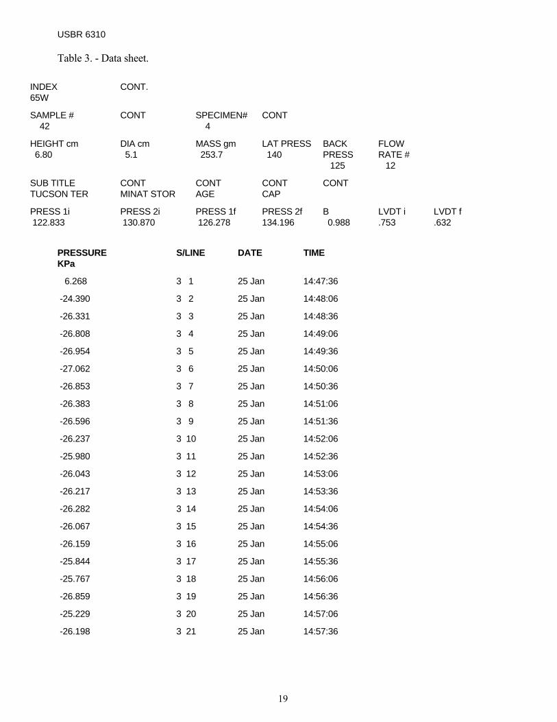
materials having low permeabilities (i.e., 1 x 10⁻⁴ cm/s or lower) exhibit a "delayed" response to attaining steady-state flow. Consequently, reaching a constant peak voltage requires several minutes. A plot of voltage or differential pressure versus time helps significantly in the identification of a steady-state condition, especially with materials of low permeability (figure 5). 13.22 Determine and record the steady-state pressure differential to the nearest 0.01 kPa (0.001 lbf/in2). An example of Reclamation’s computer-generated data sheet is shown in table 3. 13.23 Take photographs of the tested rock specimens. 13.24 After completion of the test, disassemble the test setup and clean the test area and the equipment. 13.25 Calculate and record the coefficient of permeability (see section 14). 13.26 Prepare a report (see section 15). 14.Calculations 14.1 Calculate the coefficient of permeability of the rock core specimen as follows:
where: k=coefficient of permeability = (cm/s) q=constant flow rate (cm3/s) from table 2
Hs=height of rock specimen (cm) γF=specific weight of fluid (kN/cm3) AS=cross-sectional area of specimen (cm2) ΔV=voltage change at steady state (mV) CT =calibration constant of the
transducer (kPa/mV) (see figure 6)
where: D =diameter of specimen 14.3 Calculate the hydraulic gradient as follows:
Note 5.-To obtain k in ft/yr, divide the value of k in equation 1 by 9.67 x 10-7 15.Report 15.1 The report shall include: 15.1.1 Source.-Source of sample including project name and location, date of sampling, and, if known, storage environment. The location may be specified in terms of borehole number and depth of sample from collar of hole. 15.1.2 Appearance.-Physical description of specimen including rock type; location and orientation of discontinuities, such as apparent weakness planes, bedding planes, schistosity; as well as large inclusions or inhomogeneities, if any.
C . V . A . H . q
= kTs
Fs
Δγ
1
D 4 = A 2
sπ
2
γ FS
T
HC . V = Gradient Hydraulic = i Δ
3

USBR 6258-09
16
Figure 5. - Plot of pressure (mV x Ct) versus time.
Figure 6. - Transducer calibration curve: value of CT.

USBR 6310-09
17
15.1.3 Moisture.-General indication of the moisture condition of the test specimen at the time of testing, such as saturated, as received, laboratory air dry, or oven dry. Some cases may require reporting the actual moisture content as determined by procedure USBR 5300. 15.1.4 Size.-Test specimen length, diameter, the ratio of its length to diameter, and its cross-sectional area. 15.1.5. Date.-Date of testing. 15.1.6 Permeability and Gradient.-Calculated coefficient of permeability and gradient. Example of Reclamation’s computer-generated data summary is shown in table 4. 15.1.7 Picture.-Color photograph of the specimen after the test. 15.1.8 Results.-The laboratory test results shall be reported in accordance with Reclamation designations USBR 3000 and USBR 9300. 16.Precision and Bias The precision and bias for this designation have not been determined. Any variation observed in the data is just as likely to be caused by specimen variation as by operator or laboratory testing variations. Because of the variability of rock, this test procedure has no reference value.

USBR 6310
19
Table 3. - Data sheet.
INDEX 65W
CONT.
SAMPLE # 42
CONT SPECIMEN# 4
CONT
HEIGHT cm 6.80
DIA cm 5.1
MASS gm 253.7
LAT PRESS 140
BACK PRESS 125
FLOW RATE # 12
SUB TITLE TUCSON TER
CONT MINAT STOR
CONT AGE
CONT CAP
CONT
PRESS 1i 122.833
PRESS 2i 130.870
PRESS 1f 126.278
PRESS 2f 134.196
B 0.988
LVDT i .753
LVDT f .632
PRESSURE KPa
S/LINE DATE TIME
6.268 3 1 25 Jan 14:47:36
-24.390 3 2 25 Jan 14:48:06
-26.331 3 3 25 Jan 14:48:36
-26.808 3 4 25 Jan 14:49:06
-26.954 3 5 25 Jan 14:49:36
-27.062 3 6 25 Jan 14:50:06
-26.853 3 7 25 Jan 14:50:36
-26.383 3 8 25 Jan 14:51:06
-26.596 3 9 25 Jan 14:51:36
-26.237 3 10 25 Jan 14:52:06
-25.980 3 11 25 Jan 14:52:36
-26.043 3 12 25 Jan 14:53:06
-26.217 3 13 25 Jan 14:53:36
-26.282 3 14 25 Jan 14:54:06
-26.067 3 15 25 Jan 14:54:36
-26.159 3 16 25 Jan 14:55:06
-25.844 3 17 25 Jan 14:55:36
-25.767 3 18 25 Jan 14:56:06
-26.859 3 19 25 Jan 14:56:36
-25.229 3 20 25 Jan 14:57:06
-26.198 3 21 25 Jan 14:57:36


USBR 6310
21
Table 4. - Summary sheet. Index No. 65W Sample No. 42 Specimen No. 4 Height 6.80 cm Diameter 5.1 cm Mass 253.7 gm Lateral Pressure 0.97 MPa (140 lbf/in^2) Back Pressure 0.87 MPa (125 lbf/in^2) Flow Rate 2.694E-05 cm^3/s (95.19E-11 ft^3/s) Spec Wet Unit Wt. 1.826 gm/cm^3 ( 114.0 lbm/ft^3) Coefficent of Permeability 263.94E-10 cm/s (27.3E-03 ft/yr) Gradient 49.964 TIME (min)
PRESSURE (KPa)
0.0 -32.599 .5 -1.941 1.0 0.000 1.5 0.477 2.0 0.623 2.5 0.731 3.0 0.522 3.5 0.052 4.0 0.265 4.5 -0.094 5.0 -0.351 5.5 -0.288 6.0 -0.114 6.5 -0.049 7.0 -0.264 7.5 -0.172 8.0 -0.487 8.5 -0.564 9.0 0.528 10.0 -0.133