multi-media installation guide cable types two basic types of cable are used in multimedia...
TRANSCRIPT
Multi-Media Installation Guide
Coaxial Page 2
Data Plug Page 7
Data Jack Page 10
Telephone Page 13
Splicing Page 15
2
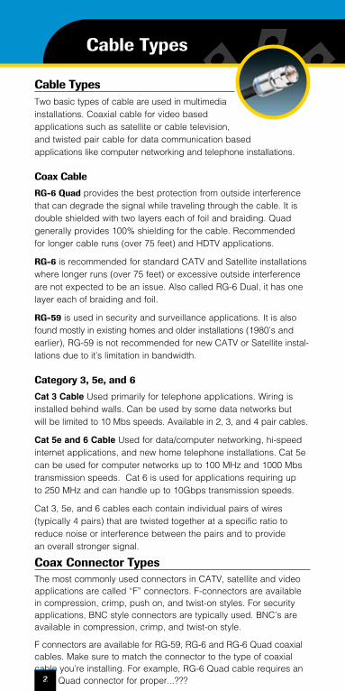
Cable TypesTwo basic types of cable are used in multimedia installations. Coaxial cable for video based applications such as satellite or cable television, and twisted pair cable for data communication based applications like computer networking and telephone installations.
Coax Cable
RG-6 Quad provides the best protection from outside interference that can degrade the signal while traveling through the cable. It is double shielded with two layers each of foil and braiding. Quad generally provides 100% shielding for the cable. Recommended for longer cable runs (over 75 feet) and HDTV applications.
RG-6 is recommended for standard CATV and Satellite installations where longer runs (over 75 feet) or excessive outside interference are not expected to be an issue. Also called RG-6 Dual, it has one layer each of braiding and foil.
RG-59 is used in security and surveillance applications. It is also found mostly in existing homes and older installations (1980’s and earlier), RG-59 is not recommended for new CATV or Satellite instal-lations due to it’s limitation in bandwidth.
Category 3, 5e, and 6
Cat 3 Cable Used primarily for telephone applications. Wiring is installed behind walls. Can be used by some data networks but will be limited to 10 Mbs speeds. Available in 2, 3, and 4 pair cables.
Cat 5e and 6 Cable Used for data/computer networking, hi-speed internet applications, and new home telephone installations. Cat 5e can be used for computer networks up to 100 MHz and 1000 Mbs transmission speeds. Cat 6 is used for applications requiring up to 250 MHz and can handle up to 10Gbps transmission speeds.
Cat 3, 5e, and 6 cables each contain individual pairs of wires (typically 4 pairs) that are twisted together at a specific ratio to reduce noise or interference between the pairs and to provide an overall stronger signal.
Coax Connector TypesThe most commonly used connectors in CATV, satellite and video applications are called “F” connectors. F-connectors are available in compression, crimp, push on, and twist-on styles. For security applications, BNC style connectors are typically used. BNC’s are available in compression, crimp, and twist-on style.
F connectors are available for RG-59, RG-6 and RG-6 Quad coaxial cables. Make sure to match the connector to the type of coaxial cable you’re installing. For example, RG-6 Quad cable requires an RG-6 Quad connector for proper...???
Cable Types
3
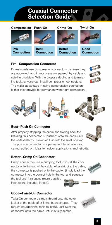
Twist-OnCrimp-OnPush-OnCompression
BestConnection
BetterConnection
GoodConnection
Good—Twist-On Connector
Twist-On connectors simply thread onto the outer jacket of the cable after it has been stripped. They require no additional tools to install. Just twist the connector onto the cable until it is fully seated.
Best—Push On Connector
After properly stripping the cable and folding back the braiding, this connector is “pushed” onto the cable until the white dielectric is even or flush with the small opening. The push-on connector is a permanent termination and cannot pulled off. Ideal for indoor applications and retrofits.
Pro—Compression Connector
Professionals use compression connectors because they are approved, and in most cases—required, by cable and satellite providers. With the proper stripping and terminat-ing tools, anyone can install compression connectors. The major advantage in using compression connectors is that they provide for permanent watertight connection.
Better—Crimp On Connector
Crimp connectors use a crimping tool to install the con-nector onto the end of the cable. After stripping the cable, the connector is pushed onto the cable. Simply load the connector into the correct hole in the tool and squeeze the tool until it releases (more detailed instructions included in tool).
Coaxial Connector Selection Guide
ProConnection
4
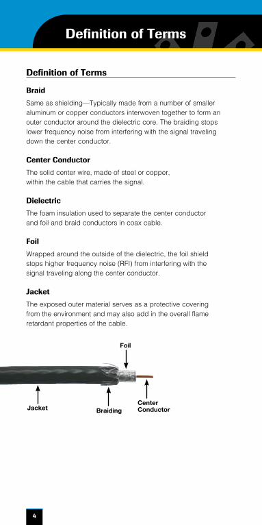
Definition of Terms
Definition of Terms
Braid
Same as shielding—Typically made from a number of smaller aluminum or copper conductors interwoven together to form an outer conductor around the dielectric core. The braiding stops lower frequency noise from interfering with the signal traveling down the center conductor.
Center Conductor
The solid center wire, made of steel or copper, within the cable that carries the signal.
Dielectric
The foam insulation used to separate the center conductor and foil and braid conductors in coax cable.
Foil
Wrapped around the outside of the dielectric, the foil shield stops higher frequency noise (RFI) from interfering with the signal traveling along the center conductor.
Jacket
The exposed outer material serves as a protective covering from the environment and may also add in the overall flame retardant properties of the cable.
Center Conductor
Foil
Jacket Braiding
5
Coaxial Installation Steps
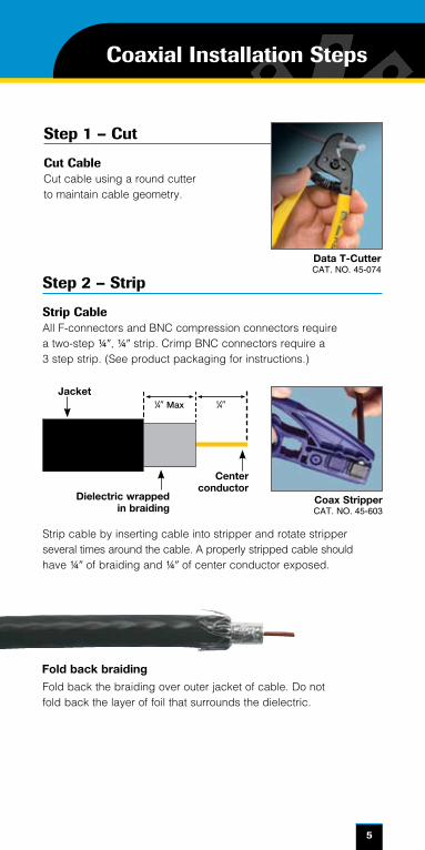
Fold back the braiding over outer jacket of cable. Do not fold back the layer of foil that surrounds the dielectric.
Step 1 – Cut
Cut CableCut cable using a round cutter to maintain cable geometry.
1⁄49 Max 1⁄49 Jacket
Dielectric wrapped in braiding
Center conductor
Coax StripperCAT. NO. 45-603
Fold back braiding
Step 2 – Strip
Strip CableAll F-connectors and BNC compression connectors require a two-step ¼9, ¼9 strip. Crimp BNC connectors require a 3 step strip. (See product packaging for instructions.)
Data T-CutterCAT. NO. 45-074
Strip cable by inserting cable into stripper and rotate stripper several times around the cable. A properly stripped cable should have ¼9 of braiding and ¼9 of center conductor exposed.
6
Coaxial Installation Steps
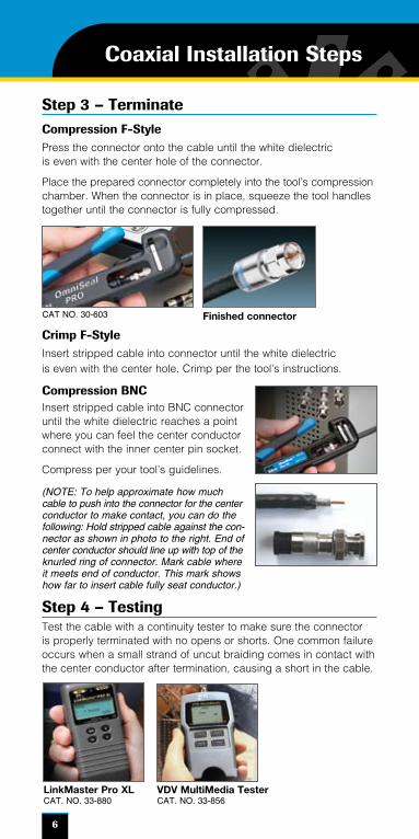
Step 3 – TerminateCompression F-StylePress the connector onto the cable until the white dielectric is even with the center hole of the connector.
Place the prepared connector completely into the tool’s compression chamber. When the connector is in place, squeeze the tool handles together until the connector is fully compressed.
Step 4 – TestingTest the cable with a continuity tester to make sure the connector is properly terminated with no opens or shorts. One common failure occurs when a small strand of uncut braiding comes in contact with the center conductor after termination, causing a short in the cable.
Finished connectorCAT NO. 30-603
LinkMaster Pro XLCAT. NO. 33-880
VDV MultiMedia TesterCAT. NO. 33-856
Crimp F-StyleInsert stripped cable into connector until the white dielectric is even with the center hole. Crimp per the tool’s instructions.
Compression BNCInsert stripped cable into BNC connector until the white dielectric reaches a point where you can feel the center conductor connect with the inner center pin socket.
Compress per your tool’s guidelines.
(NOTE: To help approximate how much cable to push into the connector for the center conductor to make contact, you can do the following: Hold stripped cable against the con-nector as shown in photo to the right. End of center conductor should line up with top of the knurled ring of connector. Mark cable where it meets end of conductor. This mark shows how far to insert cable fully seat conductor.)
Cable Pulling Tips
Maximum pulling tension—25 lbs. Minimum bending radius—4 times diameter of cable 12 inches from power lines 4 feet from motors or transformers 12 inches from fluorescent lighting Should cross perpendicular to power lines Cable untwisting allowed after termination:
n 3 inches for Category 3 cable
n 0.5 inches for Category 5e and Category 6 cable
Avoid kinking or bending cable. Cable ties should not be overly tight. Don’t use standard staples to support cable as they may crush the cable.
7
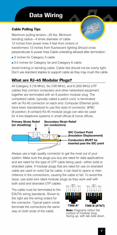
Always use a high quality connector to get the most out of your system. Make sure the plugs you buy are rated for data applications and are rated for the type of UTP cable being used—either solid or stranded cable. If modular plugs that are rated for use on stranded cable are used on solid Cat 5e cable, it can lead to opens or inter-mittence in the connections, causing the cable to fail. To avoid this issue, use solid wire rated modular plugs as they work well with both solid and stranded UTP cables.
The cable must be terminated to the EIA/TIA wiring standards. Shown to the right are the wiring orders for the connector. Typical patch cords terminate the connections the same way on both ends of the cable.
Data Wiring
T568-A* T568-B (AT&T)
Note: Diagrams reflect flat surface of modular plug facing up, with tab side down.
What are RJ-45 Modular Plugs?All Category 3 (16 MHz), 5e (100 MHz), and 6 (250 MHz) UTP cables that connect computers and other networked equipment together are terminated with an 8 position modular plug. The completed cable, typically called a patch cord, is terminated with an RJ-45 connector on each end. Computer Ethernet ports have been standardized to use this style of connector. 8P8C (8 position, 8 contact) RJ-45 modular plugs can also be used for 4 line telephone systems in small offices & home offices.
Primary Strain Relief(on sheathing)
IDC Contact Point(Insulation Displacement)
Conductors MUST be inserted past the IDC point
Secondary Strain Relief(on conductors)
8
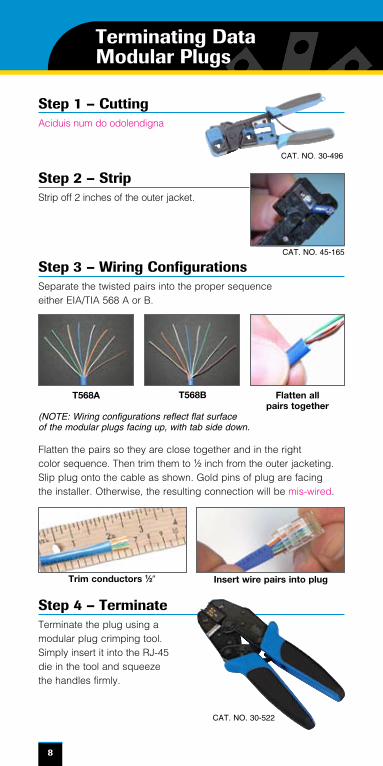
Step 2 – StripStrip off 2 inches of the outer jacket.
Step 1 – CuttingAciduis num do odolendigna
Flatten the pairs so they are close together and in the right color sequence. Then trim them to 1⁄2 inch from the outer jacketing. Slip plug onto the cable as shown. Gold pins of plug are facing the installer. Otherwise, the resulting connection will be mis-wired.
Step 4 – TerminateTerminate the plug using a modular plug crimping tool. Simply insert it into the RJ-45 die in the tool and squeeze the handles firmly.
Flatten all pairs together
T568A T568B
Terminating Data Modular Plugs
CAT. NO. 45-165
(NOTE: Wiring configurations reflect flat surface of the modular plugs facing up, with tab side down.
CAT. NO. 30-522
Step 3 – Wiring ConfigurationsSeparate the twisted pairs into the proper sequence either EIA/TIA 568 A or B.
Trim conductors 1⁄29 Insert wire pairs into plug
CAT. NO. 30-496
9
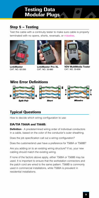
Step 5 – TestingTest the cable with a continuity tester to make sure cable is properly terminated with no opens, shorts, reversals, or miswires.
Typical QuestionsHow to decide which wiring configuration to use:
EIA/TIA T568A and T568B:
Definition - A predetermined wiring order of individual conductors in a cable, based on the color of the conductor’s outer sheathing.
Does the job specification call out a wiring configuration?
Does the customer/end user have a preference for T568A or T568B?
Are you adding on to an existing wiring structure? If so, your new cabling should match the existing wiring.
If none of the factors above apply, either T568A or T568B may be used. It is important to ensure that the workstation connectors and the patch cord are wired to the same pattern. T568B is commonly used in commercial installations, while T568A is prevalent in residential installations.
Testing Data Modular Plugs
LinkMasterCAT. NO. 62-200
LinkMaster Pro XLCAT. NO. 33-880
1
2
3
6
4
5
7
8
1
2
3
6
4
5
7
8
Split Pair
1
2
3
6
4
5
7
8
1
2
3
6
4
5
7
8
Short
1
2
3
6
4
5
7
8
1
2
3
6
4
5
7
8
Miswire
1
2
3
6
4
5
7
8
1
2
3
6
4
5
7
8
Split Pair
1
2
3
6
4
5
7
8
1
2
3
6
4
5
7
8
Short
1
2
3
6
4
5
7
8
1
2
3
6
4
5
7
8
Miswire
1
2
3
6
4
5
7
8
1
2
3
6
4
5
7
8
Split Pair
1
2
3
6
4
5
7
8
1
2
3
6
4
5
7
8
Short
1
2
3
6
4
5
7
8
1
2
3
6
4
5
7
8
Miswire
Wire Error Definitions
VDV MultiMedia TesterCAT. NO. 33-856
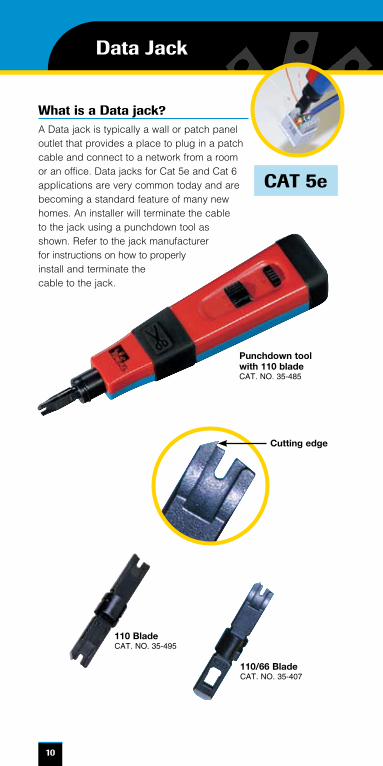
What is a Data jack?A Data jack is typically a wall or patch panel outlet that provides a place to plug in a patch cable and connect to a network from a room or an office. Data jacks for Cat 5e and Cat 6 applications are very common today and are becoming a standard feature of many new homes. An installer will terminate the cable to the jack using a punchdown tool as shown. Refer to the jack manufacturer for instructions on how to properly install and terminate the cable to the jack.
10
Data Jack
CAT 5e
Punchdown tool with 110 bladeCAT. NO. 35-485
Cutting edge
110 BladeCAT. NO. 35-495
110/66 BladeCAT. NO. 35-407
11
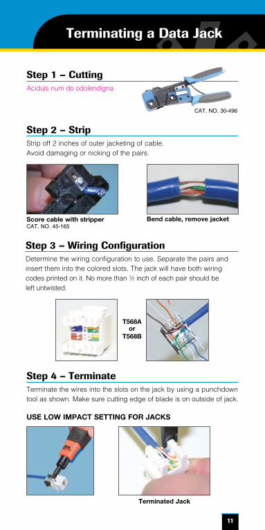
Step 2 – StripStrip off 2 inches of outer jacketing of cable. Avoid damaging or nicking of the pairs.
Step 3 – Wiring ConfigurationDetermine the wiring configuration to use. Separate the pairs and insert them into the colored slots. The jack will have both wiring codes printed on it. No more than 1⁄2 inch of each pair should be left untwisted.
Step 4 – TerminateTerminate the wires into the slots on the jack by using a punchdown tool as shown. Make sure cutting edge of blade is on outside of jack.
Terminating a Data Jack
USE LOW IMPACT SETTING FOR JACKS
Score cable with stripperCAT. NO. 45-165
Bend cable, remove jacket
T568A or
T568B
Terminated Jack
Step 1 – CuttingAciduis num do odolendigna
CAT. NO. 30-496

12
Step 5 – Testing
Testing the connections
Once you have everything terminated it is advised to test the cabling using a wiremap tester. Check for opens, shorts, split pairs, reversals, and miswires.
Tester Choices
VDV MultiMedia TesterCAT. NO. 33-856
LinkMasterCAT. NO. 62-200
Testing a Data Jack
LinkMaster Pro XLCAT. NO. 33-880
See page 9 for wire error definitions.
13
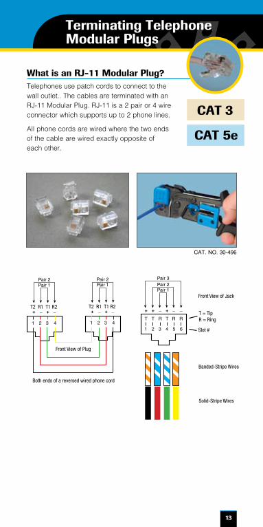
What is an RJ-11 Modular Plug?Telephones use patch cords to connect to the wall outlet.. The cables are terminated with an RJ-11 Modular Plug. RJ-11 is a 2 pair or 4 wire connector which supports up to 2 phone lines.
All phone cords are wired where the two ends of the cable are wired exactly opposite of each other.
CAT 5e
CAT 3
Front View of Jack
T = TipR = Ring
Slot #
Banded-Stripe Wires
Solid-Stripe Wires
T2 R1 T1 R2 T2 R1 T1 R2
Front View of Plug
Both ends of a reversed wired phone cord
Front View of Jack
T = TipR = Ring
Slot #
Banded-Stripe Wires
Solid-Stripe Wires
T2 R1 T1 R2 T2 R1 T1 R2
Front View of Plug
Both ends of a reversed wired phone cord
CAT. NO. 30-496
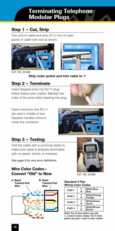
Terminating Telephone Modular Plugs
R T T R T R R T1 2 3 4 5 6 7 8
- + + - + - - +
Pair 1Pair 2
Pair 3
Pair 4
POLARITY
TIP
RING
TIP
RING
TIP
RING
TIP
RING
Pair 1
Pair 2
Pair 3
Pair 4
A. Band Twisted-Pair Wire
B. Solid Twisted-Pair Wire
14
Step 1 – Cut, StripTrim end of cable and strip off 1⁄4 inch of outer jacket of cable with tool as shown.
Step 2 – TerminateInsert stripped wires into RJ-11 plug (follow below color codes). Maintain the order of the wires while inserting into plug.
Strip outer jacket and trim cable to 1⁄49
Insert connector into RJ-11 die nest in middle of tool. Squeeze handles firmly to crimp the connector.
Step 3 – TestingTest the cable with a continuity tester to make sure cable is properly terminated with no opens, shorts, or miswires.
Wire Color Codes— Convert “Old” to New
Standard 4-Pair Wiring Color Codes
PAIR 1 TR
White/Blue Blue
PAIR 2 TR
White/Orange Orange
PAIR 3 TR
White/Green Green
PAIR 4 TR
White/Brown Brown
Note: For 6-wire jacks use pair 1, 2 and 3 color codes. For 4-wire jacks use pair 1 and 2 color codes.
CAT. NO. 30-496
See page 9 for wire error definitions.
CAT. NO. 33-856
Terminating Telephone Modular Plugs
15
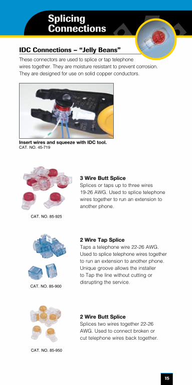
IDC Connections – “Jelly Beans”These connectors are used to splice or tap telephone wires together. They are moisture resistant to prevent corrosion. They are designed for use on solid copper conductors.
3 Wire Butt SpliceSplices or taps up to three wires 19-26 AWG. Used to splice telephone wires together to run an extension to another phone.
2 Wire Tap Splice Taps a telephone wire 22-26 AWG. Used to splice telephone wires together to run an extension to another phone. Unique groove allows the installer to Tap the line without cutting or disrupting the service.
2 Wire Butt SpliceSplices two wires together 22-26 AWG. Used to connect broken or cut telephone wires back together.
CAT. NO. 85-925
CAT. NO. 85-900
CAT. NO. 85-950
Splicing Connections
Insert wires and squeeze with IDC tool.CAT. NO. 45-719

IDEAL INDUSTRIES, INC.Becker Place, Sycamore, IL 60178, USA / 815-895-5181 • 800-435-0705 in USA
International offices:Australia • Brazil • Canada • China • Germany • Mexico • UK
For complete sales office contact information, visit us at: www.idealindustries.com
©2008 IDEAL INDUSTRIES, INC.Printed in U.S.A.
Form No. P-28042/08