module 3 - tippenergy.ie · 3 forward. • this document uses extracts from, and makes references...
TRANSCRIPT
Module 3.4
Calculation of U-value
Construction with thermal bridging
2
Learning Outcomes
• On successful completion of this module
learners will be able to
- Describe the procedure for the calculation of
U-values for constructions with thermal bridging.
3
Forward.
• This document uses extracts from, and makes
references to, EN ISO 6946 : 2007
Building components and building elements -
Thermal resistance and thermal transmittance -
Calculation method.
• The content of this document is not a substitute
for the standard. To properly apply the standard
one must have the complete document.
• Standards available from www.iso.org.
4
Introduction to thermal bridging.
• Thermal bridging occurs in building envelopes when
materials with high thermal conductivity, such as steel
and concrete, create pathways for heat loss that bypass
thermal insulation.
• When these poor insulating materials provide an
uninterrupted “short circuit” between the interior and
exterior of a building, the thermal bridge can result in
a) accelerated heat loss through that area,
b) localised cold spots on the interior of a wall that may
cause a risk of condensation.
• This effect is most significant in cold climates during the
winter when the indoor-outdoor temperature difference is
greatest. Reference: http://wiki.aia.org/WikiPages/ThermalBridging.aspx
- continued.
• Thermal bridging can also occurs in building envelopes when gaps or breaks in the insulation envelope create pathways for heat loss that bypass thermal insulation.
• The reduced or missing insulation can allow warm inside air make contact with cold external surfaces.
• This bypass of the insulation will also cause accelerated heat loss through that area, and localised cold spots on the interior.
6
Identification of thermal bridging.
• Take any heat loss surface, i.e. floor, wall, roof, etc.
• Thermal bridging must be considered if there is more
than one possible heat flow path through that surface.
• Typical construction details around doors and windows
are treated separately. The are not included when
calculating thermal bridging for that wall.
• If the thermal bridge allows for two or more possible heat
flow paths, in the main body of the floor, wall, roof. etc.
then its effect must be considered.
7
– continued.
• Take heat loss through the timber frame construction show on the next page.
• One resistance layer is made up of two very different materials, timber and mineral wool insulation.
• The poor insulator, timber, provides an uninterrupted “short circuit” through the insulation, between the interior and exterior of a building.
• The timber create pathways for heat loss that bypass the insulation.
• This reduces the effectiveness of the insulation and its effect must be included in the calculation of the U-value of the wall.
8
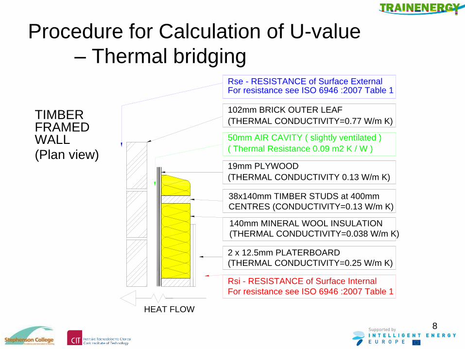
Procedure for Calculation of U-value
– Thermal bridging
TIMBER
HEAT FLOW
(THERMAL CONDUCTIVITY=0.25 W/m K)
2 x 12.5mm PLATERBOARD
(THERMAL CONDUCTIVITY=0.038 W/m K)
140mm MINERAL WOOL INSULATION
CENTRES (CONDUCTIVITY=0.13 W/m K)
38x140mm TIMBER STUDS at 400mm
19mm PLYWOOD
(THERMAL CONDUCTIVITY 0.13 W/m K)
(THERMAL CONDUCTIVITY=0.77 W/m K)
102mm BRICK OUTER LEAF
FRAMEDWALL
Rse - RESISTANCE of Surface External
Rsi - RESISTANCE of Surface Internal
For resistance see ISO 6946 :2007 Table 1
For resistance see ISO 6946 :2007 Table 1
( Thermal Resistance 0.09 m2 K / W )
50mm AIR CAVITY ( slightly ventilated )
(Plan view)
9
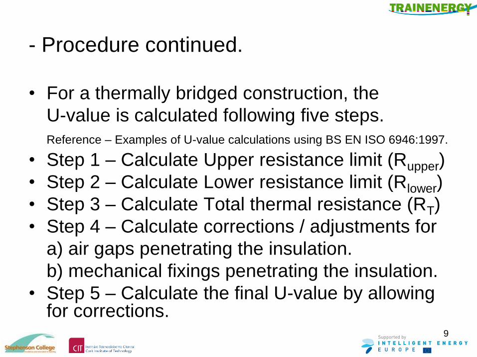
- Procedure continued.
• For a thermally bridged construction, the
U-value is calculated following five steps.
Reference – Examples of U-value calculations using BS EN ISO 6946:1997.
• Step 1 – Calculate Upper resistance limit (Rupper)
• Step 2 – Calculate Lower resistance limit (Rlower)
• Step 3 – Calculate Total thermal resistance (RT)
• Step 4 – Calculate corrections / adjustments for
a) air gaps penetrating the insulation.
b) mechanical fixings penetrating the insulation.
• Step 5 – Calculate the final U-value by allowing for corrections.
10
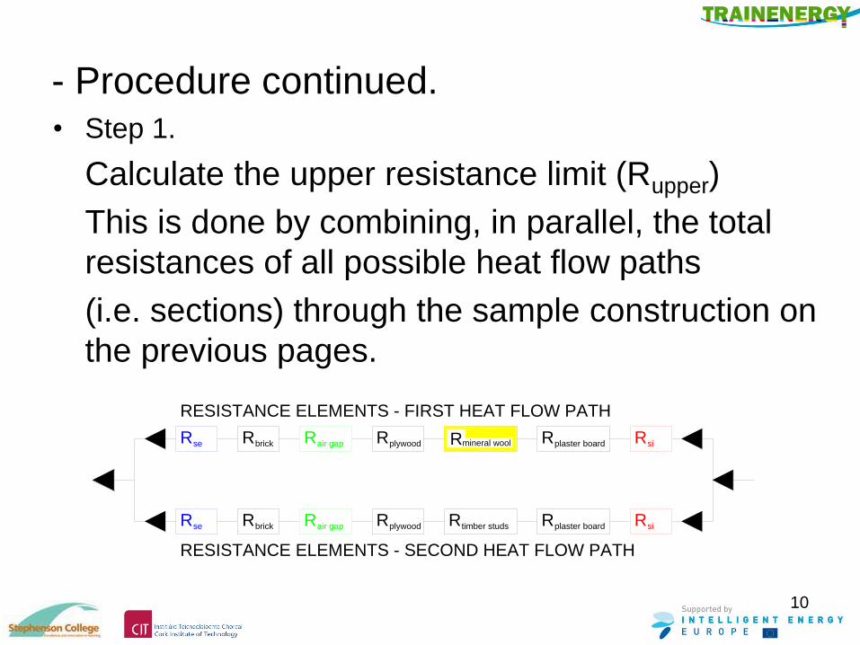
- Procedure continued. • Step 1.
Calculate the upper resistance limit (Rupper)
This is done by combining, in parallel, the total
resistances of all possible heat flow paths
(i.e. sections) through the sample construction on
the previous pages.
mineral wool Rsi
siRtimber studsR Rplaster boardplywoodRRair gapRse brickR
RESISTANCE ELEMENTS - FIRST HEAT FLOW PATH
RESISTANCE ELEMENTS - SECOND HEAT FLOW PATH
RbrickseR air gapR Rplywood plaster boardRR
11
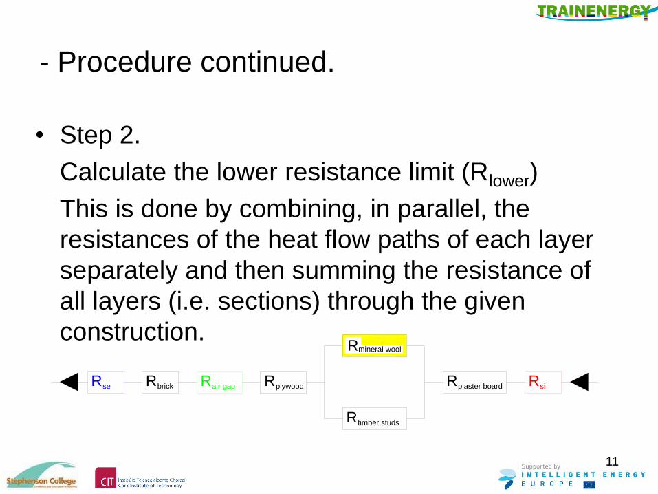
- Procedure continued.
• Step 2.
Calculate the lower resistance limit (Rlower)
This is done by combining, in parallel, the
resistances of the heat flow paths of each layer
separately and then summing the resistance of
all layers (i.e. sections) through the given
construction.
RbrickseR air gapR Rplywood plaster boardR Rsi
timber studsR
mineral woolR
12
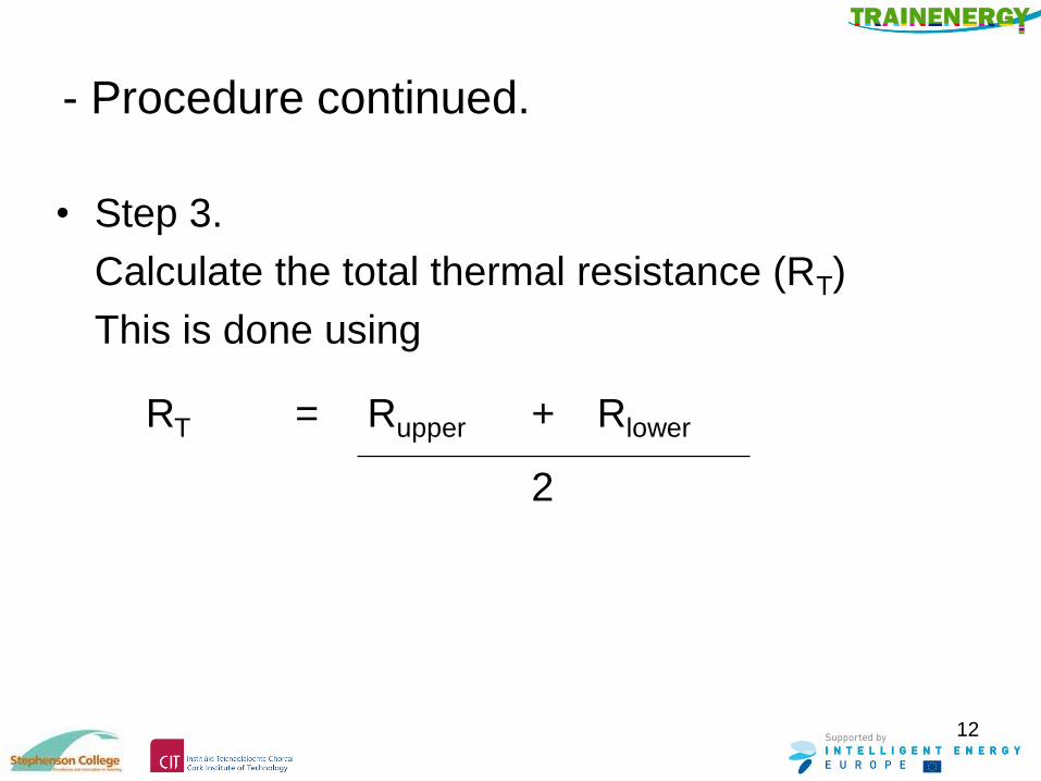
- Procedure continued.
• Step 3.
Calculate the total thermal resistance (RT)
This is done using
RT = Rupper + Rlower
2

13
- Procedure continued.
• Step 4
Procedure - Calculate, where appropriate,
a) corrections for air gaps ( ∆Ug ) in the
insulation layer.
b) correction for mechanical fasteners ( ∆Uf ) in
the insulation layer.
Note: Procedures for corrections may vary between
countries. One procedure is described in BRE442 –
Conventions for U-value calculations, 2006, sections
4.9.1, 4.9.2 and 4.9.3.
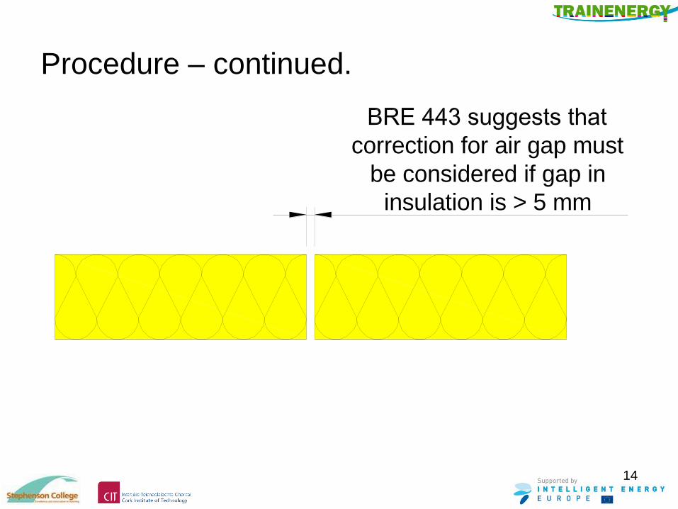
Procedure – continued.
14
correction for air gap must
be considered if gap in
insulation is > 5 mm
Procedure – continued.
• BRE443 section 4.9.2 and 4.9.3 suggests that the effect
of wall ties is negligible in an un-insulated cavity, and in
any cavity if plastic ties are used.
• Otherwise the effect of wall ties needs to be considered.
• The correction requires knowledge of the thermal
conductivity of the ties, their cross-sectional area, and
the number per square metre of wall.
• For detailed procedure see BRE442 – Conventions for
U-value calculations, 2006, sections 4.9.2 and 4.9.3.
15
16
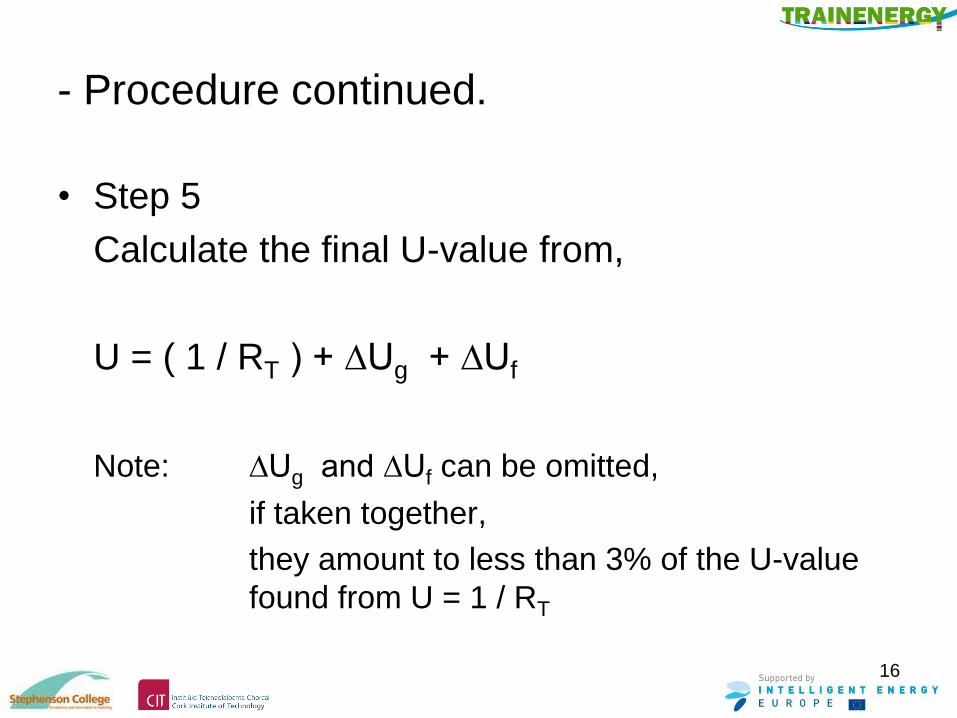
- Procedure continued.
• Step 5
Calculate the final U-value from,
U = ( 1 / RT ) + ∆Ug + ∆Uf
Note: ∆Ug and ∆Uf can be omitted,
if taken together,
they amount to less than 3% of the U-value
found from U = 1 / RT
17
Example - Step 1 – Calculating Rupper
• Procedure.
Combining, in parallel, the total resistances of all
possible heat flow paths (i.e. sections) through
the given timber frame construction
• For this construction shown on the preceding
sketch, thermal bridging occurs only at one
layer, that is the layer made up partly of 38 x
140mm timber and partly by 140mm mineral
wool.
18
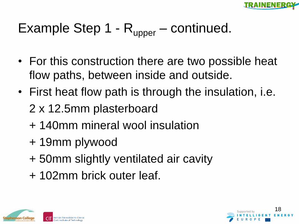
Example Step 1 - Rupper – continued.
• For this construction there are two possible heat
flow paths, between inside and outside.
• First heat flow path is through the insulation, i.e.
2 x 12.5mm plasterboard
+ 140mm mineral wool insulation
+ 19mm plywood
+ 50mm slightly ventilated air cavity
+ 102mm brick outer leaf.

19
Example Step 1 - Rupper – continued.
• Second heat flow path is through the timber, i.e.
2 x 12.5mm plasterboard
+ 38 x 140mm timber studs
+ 19mm plywood
+ 50mm slightly ventilated air cavity
+ 102mm brick outer leaf.
20
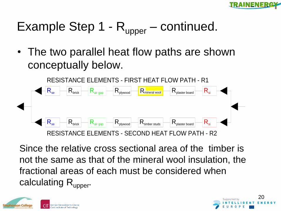
Example Step 1 - Rupper – continued.
• The two parallel heat flow paths are shown
conceptually below.
Since the relative cross sectional area of the timber is
not the same as that of the mineral wool insulation, the
fractional areas of each must be considered when
calculating Rupper.
RESISTANCE ELEMENTS - SECOND HEAT FLOW PATH - R2
RESISTANCE ELEMENTS - FIRST HEAT FLOW PATH - R1
RbrickseR air gapR Rplywood plaster boardRRtimber studs Rsi
siRmineral woolR Rplaster boardplywoodRRair gapRse brickR

21
Example Step 1 - Rupper – continued.
• The upper limit of resistance is calculated from
Rupper = 1
F1 + F2
R1 R2
F1 = the fractional area of first (insulation) heat loss path
F2 = the fractional area of second (timber) heat loss path
R1 = the total resistance of first (insulation) heat loss path
R2 = the total resistance of second (timber) heat loss path
22
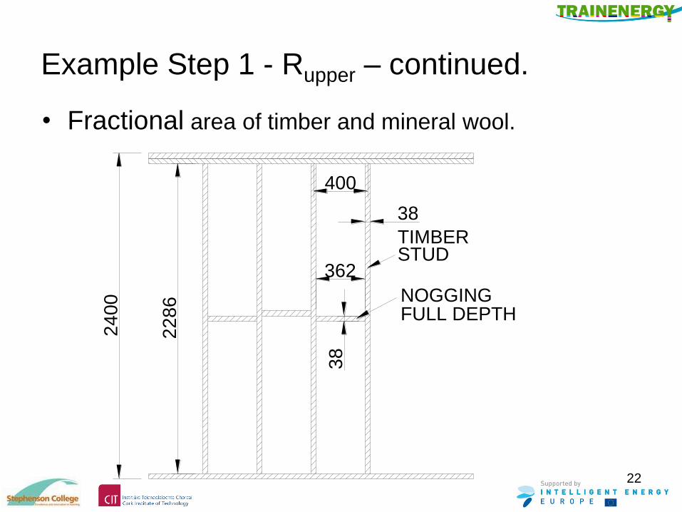
Example Step 1 - Rupper – continued.
• Fractional area of timber and mineral wool. 2
40
0
400
38
38
362STUD
NOGGING
TIMBER
FULL DEPTH
22
86
23
Example Step 1 - Rupper – continued.
• When considering the fractional area of timber
different countries may use different procedures.
• To provide inputs for this worked example the
procedures described in BRE443 section 4.5.1
have been used.
• The wall area is taken as a number of
repeatable rectangles 2400mm high x 400mm
wide.
• The percentage timber in this repeatable area is
calculated as follows.

24
Example Step 1 - Rupper – continued.
• Fractional area of timber F2 and mineral wool F1.
• Overall repeatable area
2.400 x 0.400 = 0.960 m2
• Area of timber
Vertical 2.400 x 0.038 = 0.091 m2
Horizontal 0.362 x 0.038 x 4 = 0.055 m2
Total 0.146 m2
• Fractional area of timber (F2) (0.146 / 0.960) 0.15
• Fractional area insulation(F1) ( 1 – 0.15 ) 0.85
25
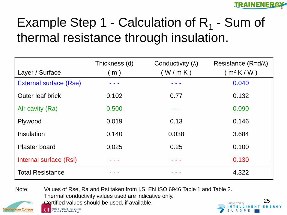
Example Step 1 - Calculation of R1 - Sum of
thermal resistance through insulation.
Layer / Surface
Thickness (d)
( m )
Conductivity (λ)
( W / m K )
Resistance (R=d/λ)
( m2 K / W )
External surface (Rse) - - - - - - 0.040
Outer leaf brick 0.102 0.77 0.132
Air cavity (Ra) 0.500 - - - 0.090
Plywood 0.019 0.13 0.146
Insulation 0.140 0.038 3.684
Plaster board 0.025 0.25 0.100
Internal surface (Rsi) - - - - - - 0.130
Total Resistance - - - - - - 4.322
Note: Values of Rse, Ra and Rsi taken from I.S. EN ISO 6946 Table 1 and Table 2.
Thermal conductivity values used are indicative only.
Certified values should be used, if available.
26
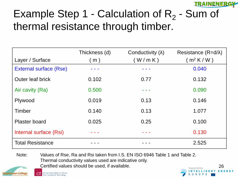
Example Step 1 - Calculation of R2 - Sum of
thermal resistance through timber.
Layer / Surface
Thickness (d)
( m )
Conductivity (λ)
( W / m K )
Resistance (R=d/λ)
( m2 K / W )
External surface (Rse) - - - - - - 0.040
Outer leaf brick 0.102 0.77 0.132
Air cavity (Ra) 0.500 - - - 0.090
Plywood 0.019 0.13 0.146
Timber 0.140 0.13 1.077
Plaster board 0.025 0.25 0.100
Internal surface (Rsi) - - - - - - 0.130
Total Resistance - - - - - - 2.525
Note: Values of Rse, Ra and Rsi taken from I.S. EN ISO 6946 Table 1 and Table 2.
Thermal conductivity values used are indicative only.
Certified values should be used, if available.
27
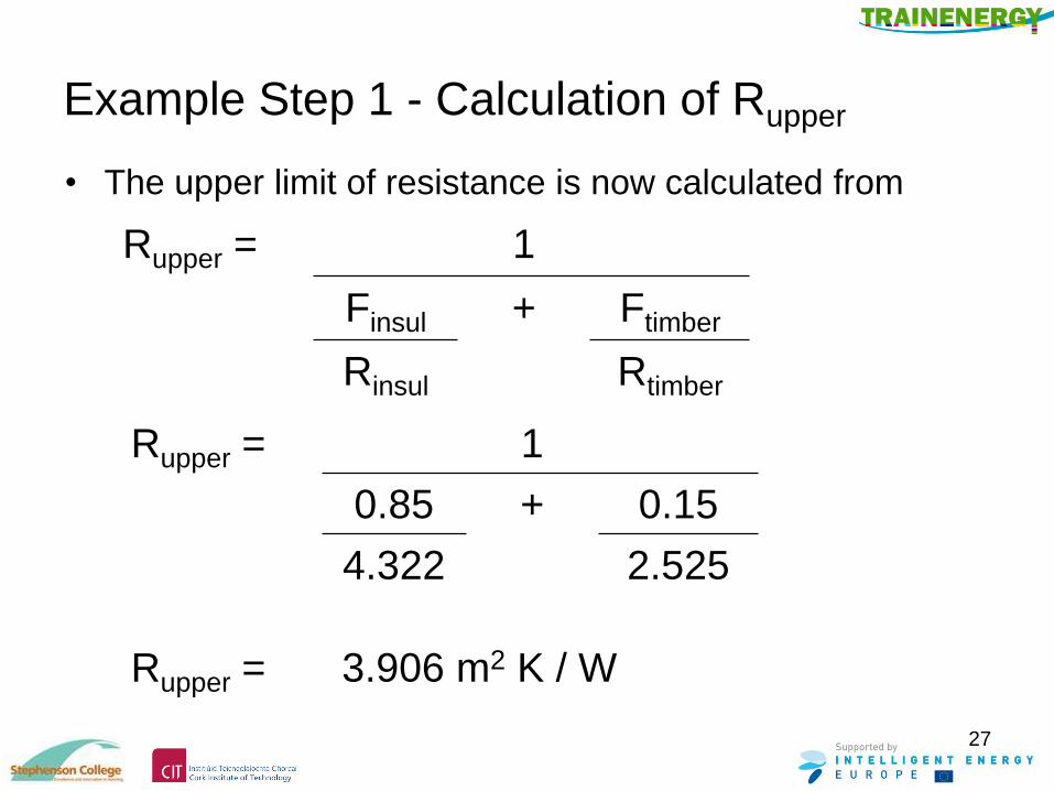
Example Step 1 - Calculation of Rupper
• The upper limit of resistance is now calculated from
Rupper = 1
Finsul + Ftimber
Rinsul Rtimber
Rupper = 1
0.85 + 0.15
4.322 2.525
Rupper = 3.906 m2 K / W
28
Example Step 2 – Calculating Rlower
• Procedure.
Combining, in parallel, the resistances of the
heat flow paths of each layer separately and
then sum the resistance of all layers (i.e.
sections) through the given construction.
• For this construction, thermal bridging occurs
only at one layer, that is the layer made up partly
of 38 x 140mm timber and partly by 140mm
mineral wool.

29
Example Step 2
– Calculating Rlower – continued
• For this construction there is only one layer with two possible heat flow paths, i.e. the layer with a combination of 140mm mineral wool insulation and 38 x 140 timber studs.
• The heat flow path will be
2 x 12.5mm plasterboard
+ (Combination of mineral wool and timber)
+ 19mm plywood
+ 50mm slightly ventilated air cavity
+ 102mm brick outer leaf.
30
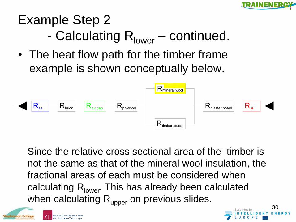
Example Step 2
- Calculating Rlower – continued.
• The heat flow path for the timber frame
example is shown conceptually below.
Since the relative cross sectional area of the timber is
not the same as that of the mineral wool insulation, the
fractional areas of each must be considered when
calculating Rlower. This has already been calculated
when calculating Rupper on previous slides.
RbrickseR air gapR Rplywood plaster boardR Rsi
timber studsR
mineral woolR

31
Example Step 2
- Calculating Rlower – continued.
• The resistance of the bridged layer is now calculated
from
Rbridged = 1
Finsul + Ftimber
Rinsul Rtimber
F insul = the fractional area of first (insulation) heat loss path
F timber = the fractional area of second (timber) heat loss path
R insul = the total resistance of first (insulation) heat loss path
R timber = the total resistance of second (timber) heat loss path
32
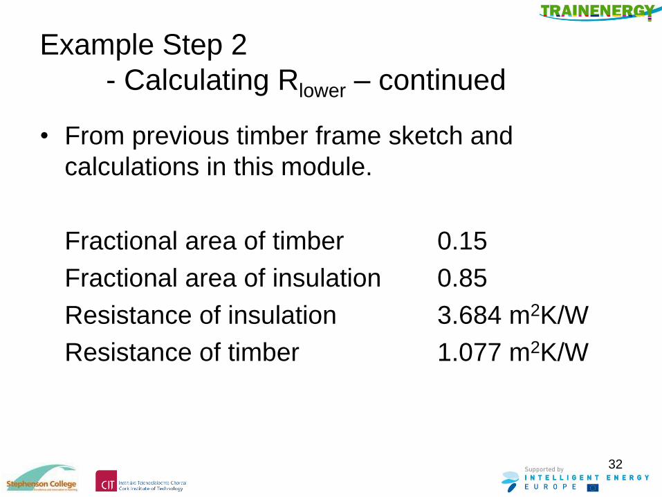
Example Step 2
- Calculating Rlower – continued
• From previous timber frame sketch and
calculations in this module.
Fractional area of timber 0.15
Fractional area of insulation 0.85
Resistance of insulation 3.684 m2K/W
Resistance of timber 1.077 m2K/W
33
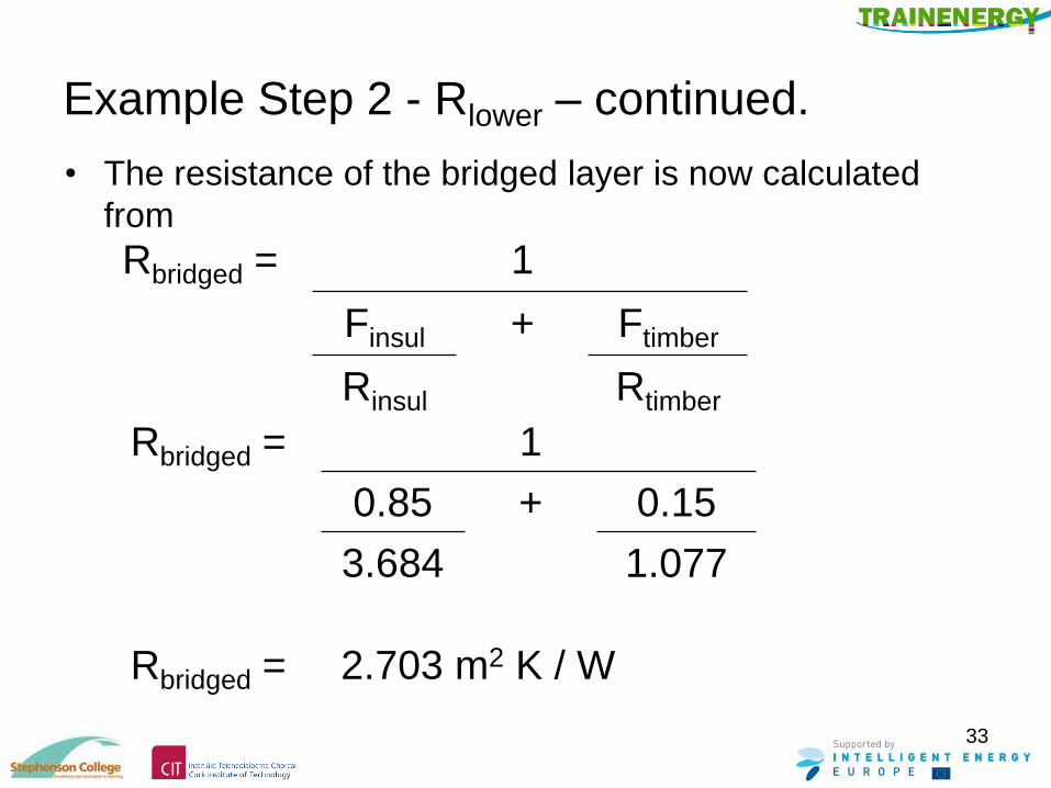
Example Step 2 - Rlower – continued.
• The resistance of the bridged layer is now calculated
from
Rbridged = 1
Finsul + Ftimber
Rinsul Rtimber
Rbridged = 1
0.85 + 0.15
3.684 1.077
Rbridged = 2.703 m2 K / W

34
Example Step 2 - Rlower – continued.
Layer / Surface
Thickness (d)
( m )
Conductivity (λ)
( W / m K )
Resistance (R=d/λ)
( m2 K / W )
External surface (Rse) - - - - - - 0.040
Outer leaf brick 0.102 0.77 0.132
Air cavity (Ra) 0.500 - - - 0.090
Plywood 0.019 0.13 0.146
Bridged layer - - - - - - 2.703
Plaster board 0.025 0.25 0.100
Internal surface (Rsi) - - - - - - 0.130
Total Resistance - - - - - - 3.341
Sum of thermal resistance through all layers
Rlower = 3.341 m2 K / W
35
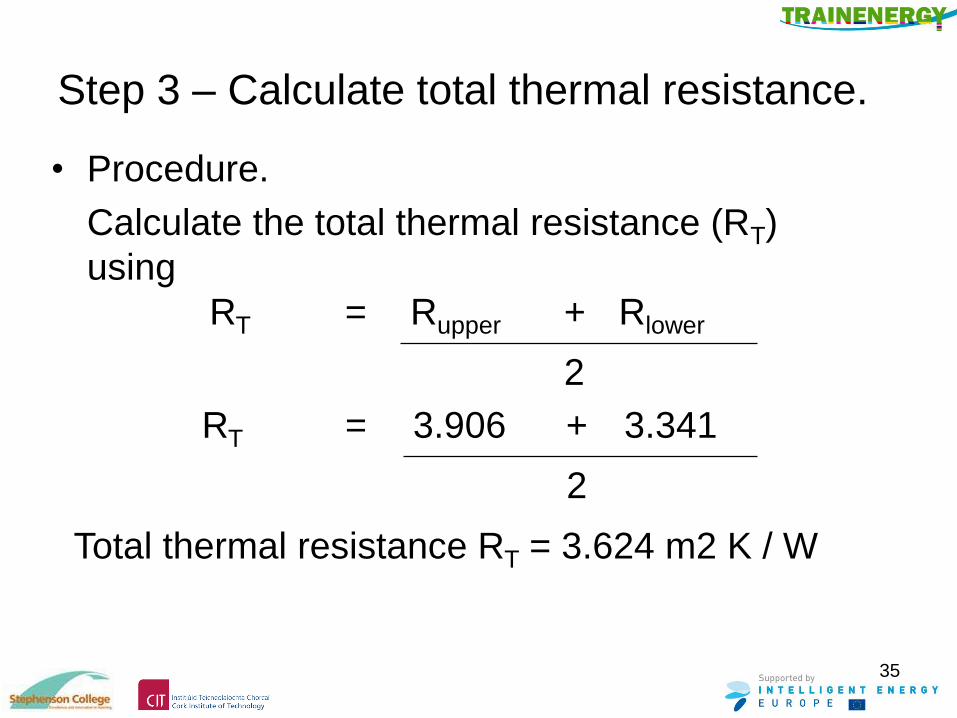
Step 3 – Calculate total thermal resistance.
• Procedure.
Calculate the total thermal resistance (RT)
using
RT = Rupper + Rlower
2
RT = 3.906 + 3.341
2
Total thermal resistance RT = 3.624 m2 K / W

36
Step 4 – Calculate corrections.
• Procedure - Calculate, where appropriate,
a) corrections for air gaps ( ∆Ug ) in the
insulation layer. That is if a gaps exceeding
5mm width penetrates the insulation.
b) correction for mechanical fasteners ( ∆Uf ) in
the insulation layer.
Note: Procedures for corrections may vary between
countries. One procedure is described in BRE442 –
Conventions for U-value calculations, 2006, sections
4.9.1, 4.9.2 and 4.9.3.
37
Step 4 - Corrections - continued.
• Corrections for air gaps ( ∆Ug ) in the insulation
layer.
• In this example no corrections are applicable,
i.e. the insulation is installed in such a way that
there are no air gaps penetrating the entire
insulation layer and no air circulation is possible
on the warm side of the insulation. • For the three possible levels of correction for air gaps see I.S. EN ISO 6946 Annex D.
• For examples of such corrections see –
“Examples of U-value calculations using BS EN ISO 6946 : 1997” published by BRE.
38
Step 4 - Corrections - continued.
• Correction for mechanical fasteners ( ∆Uf ) in the
insulation layer.
• In this example no corrections are applicable,
i.e. no mechanical fasteners penetrating the
entire insulation layer. • For the formula related correction for mechanical fastners see I.S EN ISO 6946
Annex D.
• For examples of such corrections see –
“Examples of U-value calculations using BS EN ISO 6946 : 1997” published by BRE.
39
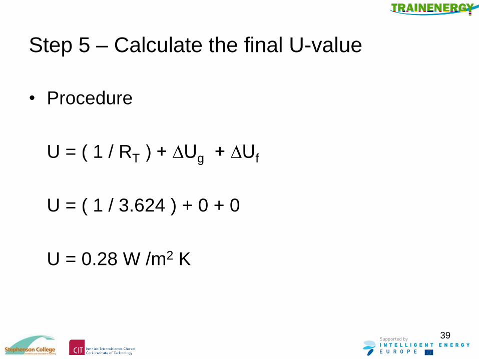
Step 5 – Calculate the final U-value
• Procedure
U = ( 1 / RT ) + ∆Ug + ∆Uf
U = ( 1 / 3.624 ) + 0 + 0
U = 0.28 W /m2 K
40
Module Summary.
• When calculating U-values for constructions with
thermally bridged elements, 5 steps are used.
• Task.
Outline each of these 5 steps.
41
Module Summary.
• Step 1 calculates the upper resistance limit
Rupper.
• Task.
Describe this step in detail and draw a sketch to
show how the resistance paths should be
arranged.

42
Module Summary.
• Step 2 calculates the upper resistance limit
Rlower.
• Task.
Describe this step in detail and draw a sketch to
show how the resistance paths should be
arranged.

43
Module Summary.
• Step 3 calculates the total thermal resistance
limit RT.
• Task.
Describe the formula needed to calculate RT.

44
Module Summary.
• Step 4 calculates the corrections for
a) air gaps penetrating the insulation
b) mechanical fixings penetrating the insulation.
• Task.
Describe some examples where these
correction factors need not be applied.
45
Module Summary.
• Step 5 calculates the thermal transmittance
value of U-value.
• Task.
Describe the formula needed to calculate the
U-value.
46
National procedures – UK, Ireland.
• When considering the fractional area of timber
included in calculations BRE 443 Section 4.5.1
states :-
For timber frame construction which conforms
with the designs in Accredited Construction
Details, additional heat loss at corners, window
surrounds, between floors etc is limited and the
associated timbers are not counted as part of
the timber fraction. This is comparable with
masonry construction where items such as
lintels and cavity closers are not counted.
47
- continued.
• BRE 443 suggests a default fraction for typical
timber frame construction as 0.15.
• A lower fraction of 0.125 may be used if specific
conditions are met.
• For further information see BRE 443 section 4.5.
48
Acknowledgements:
• The authors and publishers of this document
wish to thank the National Standards Authority of
Ireland for permission to reproduce extracts from
copyright material EN ISO 6946 : 2007 Building
components and building elements - Thermal
resistance and thermal transmittance -
Calculation method.
49
References:
• International standards.
• I.S. EN ISO 6946 : 2007 Building components and
building elements - Thermal resistance and thermal
transmittance - Calculation method.
• National standards + others.
• BRE 443 : 2006 – Convention for U-value
calculations. ISBN 1 86081 924 9
• Examples of U-value calculations using BS EN
ISO 6946 : 1997 published by BRE.
• http://wiki.aia.org/WikiPages/ThermalBridging.aspx