modelling the spray and combustion processes in diesel...
TRANSCRIPT
Modelling the spray and combustion processes in diesel engine using
coupled Euler-Eulerian and Euler-Lagrangian approach
Milan Vujanović
Faculty of Mechanical Engineering and Naval Architecture
University of Zagreb, Croatia
e-mail: [email protected]
Zvonimir Petranović
Faculty of Mechanical Engineering and Naval Architecture
University of Zagreb, Croatia
e-mail: [email protected],
ABSTRACT
The focus of this paper is to show that the existing and developed models are capable for
describing spray formation, combustion and pollutant formation processes. The Euler-Eulerian
approach was used for the spray modelling where the mathematical models of fuel jet
disintegration and droplet evaporation are used. Spray combustion is modelled using the
common Euler-Lagrangian approach. The coupling of two approaches have been performed by
running simultaneous computations on separate computational domains with constantly
exchanging mass, enthalpy and momentum sources. This research outlines the capability
employing the coupled approach. The calculated results were compared with the available
experimental data. It is concluded that the pressure and temperature evolution, combustion
process and the emissions trends are well described using this approach. The coupled
simulations could be used in further engine development retaining the high CPU efficiency
taken from the Euler-Lagrangian simulations with an increased solution accuracy in the near-
nozzle region employing the Euler-Eulerian approach.
KEYWORDS
CFD modelling, Eulerian, Lagrangian, coupling, combustion.
INTRODUCTION
Powering diesel engines and burning a vast amount of fossil fuel increases the concentration of
pollutants dangerous for human health and for the environment. The most significant
contributors are nitric oxides, carbonaceous particles, carbon monoxide and unburnt
hydrocarbons. The regulation of these pollutants has been a hot topic for several decades and
rigorous regulations are planned for the future. Huge scientific effort and time are dedicated for
determining how various factors and fuel energy conversion influence the emissions of internal
combustion engines. Detailed understanding of such processes is limited in experimental
investigations and therefore, the Computational Fluid Dynamics tools can be employed in
addition to experiments.
Numerous studies about spray processes have helped engineers establish the criteria needed to
design and develop more efficient combustion and related fuel devices while minimizing the
pollutant emissions 1, 2 and 3. The understanding of the complex nature of the fuel spray
formed by high pressure injectors in the experimental investigations is limited and this
understanding can be significantly improved by numerical simulations. The numerical

modelling of spray processes is a very challenging task as compared to a single phase flow. The
challenges are due to the fluid interfaces between phases, and the property variations across the
interfaces between phases. Thus, the spray models demand complicated techniques to couple
the dynamics of the liquid droplets and the carrier gas. A variety of strategies have been
formulated during the last years in order to address this problem. In general, most of these
strategies fall into two basic formulation methods that are commonly used to couple the
dynamics of the liquid phase and the gas phase: the Eulerian-Lagrangian method and the
Eulerian-Eulerian method.
The Eulerian-Lagrangian method has been firstly used in the engineering applications 4, 5, 6,
7 and many others in recent years. In this approach, the spray is represented by finite numbers
of parcels assuming that all the droplets within one parcel have similar size and the same
physical properties. The motion and transport through the flow field are solved using the
Lagrangian formulation, whilst the continuous gas phase is described solving the common
conservation equations. The coupling between the phases is performed introducing the source
terms for interfacial mass, momentum and energy exchange [9]. This approach have severe
limitations. It is very sensitive to the numerical grid resolution in the near nozzle region [8]
which results in inadequate description of dense sprays. However, Lagrangian approach is
suitable for calculating the diluted region where lower volume fraction of the liquid phase is
encountered. Furthermore, this approach suffers from the statistical convergence problems, as
discussed in [10]. The Euler–Lagrangian formulation is most often used to reliably describe
sprays produced by low pressure atomisation [11].
To overcome the mentioned approach disadvantages the Euler Eulerian multiphase approach
can be employed. Here, both phases are treated as continuum and are conservation equations
are solved for each phase separately with similar numerical techniques. This approach was first
addressed by [12] and has been adopted and applied for numerical simulation, e.g., [13], [14],
[15], [16], [17], [18], [19], [20] and others.
Compared to the Lagrangian scheme, the Eulerian scheme calculation is fairly efficient for
flows of high droplet concentration, whilst the Lagrangian scheme show better solution for the
diluted flows. Knowing this, the two mentioned approaches can be used together to overcome
their disadvantages and improve the spray modelling. In this work, the coupling concept has
been presented where the validated Eulerian multiphase spray approach was used together with
the Lagrangian DDM spray approach to take advantage of the capabilities inherent in both
methods. This concept was then applied for coupled simulation of real internal combustion
engine, which is particularly challenging for such modelling. Spray was calculated by the
Eulerian multiphase spray method in a fine, non-moving mesh that covers only a small part of
the engine downstream of the nozzle exit. The Eulerian multiphase spray simulation was
coupled with single phase engine simulation performed in the coarser moving mesh that
overlaps the spray mesh. The basic idea was to couple two different simulations, the Eulerian
multiphase spray calculation in the dense spray region with the single-phase engine calculation
applying DDM in the whole computational domain. This means that two different CFD codes,
Eulerian multiphase spray code, referred here as spray code, and single-phase engine code,
referred here as engine code, were performed simultaneously simulations.
A concept for simulation of different flow regimes, both dense and dilute spray, by using the
Eulerian multiphase approach coupled by Lagrangian approach is proposed in Error!
Reference source not found.21], [22]. In this paper, a coupling of the Eulerian multiphase
spray simulation with Lagrangian DDM engine simulation was done by AVL FIRE® Code
Coupling Interface (ACCI) [23]. Coupling of two simulations means that current field values
of both simulations were used as either boundary condition values or source terms for other
simulations. In this work, the flow field of the engine code calculations were used as boundary
condition values for the Eulerian multiphase spray code calculation. In another direction, the

source terms (mass, momentum and energy) between the liquid phases and the gaseous phase
of the Eulerian multiphase spray code calculation were transferred to the gas phase calculation
of the engine code in order to synchronise the flow field.
MATHEMATICAL MODELLING
The basis of the Eulerian spray method is the multiphase approach obtained through the
ensemble averaging process of the conservation equations. The gas and the liquid phase are
considered as continuum represented by the volume fractions. The gas phase is modelled as the
primary phase, whilst the droplets are treated as secondary phase. The droplets are divided into
a finite number of classes represented by a droplet diameter range. Table 1 shows the phase and
class specification in the Eulerian multiphase size of classes approach. The vapour is
transported by a separate scalar transport equation within the gaseous phase. The phases from
2 to n-1 are the liquid droplet phases. The last phase, phase n, is modelled as the bulk liquid
phase flowing out from the nozzle.
Table 1. The phase specification of the Eulerian spray model
Phase 1 2, …, n-1 n
Content Gas mixture Droplets Bulk liquid
A set of conservation equations is being solved both for the gas and liquid phase. This leads to
a great number of conservation equations to be solved especially when defining a higher number
of droplet classes. Details on the conservation equation and the modelled source terms can be
found in [24]. Equations (1), (2) and (3) represent the mass, momentum, and enthalpy
conservation equations for phase k [23] and [24]. The terms e kl, Mkl and Hkl, stand for the
mass, momentum and enthalpy exchange terms between phase k and phase l. They contain the
complete physics of the spray model, whilst the left hand side determines the rate of change
and the convective transport. Equation (4) represents the volume fraction compatibility
condition that must be fulfilled as a prerequisite of the conservative approach.
1,
nk k
k k k kl
l l kt
v (1)
1, 1,
( )
tk k kk k k k k k k k k k
n n
kl k kl
l l k l l k
pt
vv v τ τ f
M v
(2)
1, 1,
: H
tk k kk k k k k k k k k k
n n
k k k k k k k kl k kl
l l k l l k
hh
t
dph
dt
v q q f v
v
(3)
11
n
k
k (4)

For reliable use of the Euler-Eulerian multiphase model a detailed verification has been
performed [25]. The validation has been performed comparing the liquid and vapour
penetration in comparison to the experimental data. The validation of the Euler-Lagrangian
approach was performed in [24] where the mean pressure, temperature and pollutant emissions
were compared to the experimental data. The confidence in the accuracy of the presented
approach is based on the two above mentioned model validations. It can be concluded that the
topic in [24] is calculating the pollutant emissions employing the Euler Lagrangian formulation
which is different to topic in this manuscript, whilst the topic in the [25] is parameterisation of
the breakup models employing the Euler Eulerian formulation which is different to topic in this
manuscript.
As it was previously mentioned the Euler-Lagrangian approach was used for the purpose of this
paper. Lagrangian formulation was used for tracking droplets motion through the flow field,
whilst the Euler formulation was used for solving the gaseous phase [26].
The AVL Code Coupling Interface (ACCI) was used in this work as a separate software module
to enable coupling between two different CFD simulations, the Eulerian spray multiphase
calculation and the Lagrangian DDM spray single-phase engine calculation. This module
provides the required data exchange between two simulations, i.e., two codes. Moreover, the
ACCI module provides spatial mapping of data between different meshes, which was
performed in a conservative manner based on a volume or area weighted interpolation. The
coupling was implemented as a server-client system, where Eulerian multiphase spray
simulation was calculated with the spray client and Lagrangian DDM single-phase engine
simulation was calculated with the engine client. As mentioned previously, the goal of coupled
simulation is to use the benefits of both simulations, Eulerian multiphase spray simulation and
single-phase engine simulation, when calculating the fuel injection, mixture preparation and
combustion in real engine configuration. The fuel injection process was calculated at the spray
client with a fine mesh only near the nozzle hole. Mixture preparation, combustion and nitrogen
emission formation were calculated at the engine client in whole engine configuration with
coarser moving mesh.
The 3D non-moving computational domain, used for Eulerian multiphase spray simulation, is
only a small part of the 3D moving engine domain.
As addressed, the ACCI was used to couple two separate domains: spray domain calculated
with spray client applying the Eulerian multiphase spray method, and engine domain calculated
with engine client applying the Lagrangian DDM method. ACCI performs the spatial mapping
between different meshes and transfers the attribute values between them. The main task of the
ACCI is to exchange either the boundary condition values or source terms between two clients.
The data exchange was done at each coupling time step. Initialization of coupled simulation
must be performed as the first step where the engine client sends the initial conditions such as
pressure, temperature, turbulence kinetic energy, etc., to the coupling server. The spray client
gets the initialization information from the coupling server.
The spray client transfers the source terms from the whole spray 3D volume mesh to the
overlapping domain in the engine mesh. Since the spray client and engine client use different
meshes, the source terms mapping was performed in a conservative manner using a weighting
factor. This factor was calculated from the intersection volumes between spray and engine mesh
according to the equation (5):
sese
s
CVwf
CV (5)

for extensive attributes such as mass or momentum sources. For example, mass source term Se in
the control volume of the engine mesh was calculated from all values in the control volumes in
spray mesh as:
.e se s
s
S wf S (6)
Figure 1 illustrates the intersection of control volume of the source-interface spray mesh CVs with
control volume of the target-interface engine mesh CVe. Source terms should be mapped from the
spray mesh to the engine mesh.
Figure 1. Intersection of control volumes between spray and engine mesh
In the case of non-extensive attributes such as mass fraction, velocity, pressure or temperature
where these attributes do not depend on the size of control volumes the weighting factor is defined
as:
. sese
e
CVwf
CV (7)
The boundary condition values (pressure, velocity, turbulence and temperature) in the 3D volume
mesh of the engine client at the end of engine time-step were mapped to the 2D surface boundaries
of the spray client. These values were used as boundary conditions in the spray calculation. For
this purpose two different boundary conditions were defined for the spray mesh, static pressure
and velocity at a face selection surface.
Liquid phases that cross the boundary of the spray mesh were treated in the engine code by
classical DDM model, producing new parcels in the engine domain. The details regarding the
bidirectional coupling between the engine and spray domain is in detailed explained in [23], [27],
and [30].
NUMERICAL SIMULATION
Since the combustion chamber geometry and the 6 hole injector configuration are symmetrical,
the calculated engine domain is only 1/6 of the total chamber with one nozzle in order to save
computational time. The Eulerian multiphase spray calculation was performed only close to the
nozzle (full conical spray domain), while the Lagrangian spray calculation, combustion and
formation of nitrogen emission were performed in the remaining combustion chamber (60
degree sector of cylinder), as illustrated in Figure 2.
CVs
CVe
CVse
CVs
CVe
CVse

Figure 2. Engine and spray domain used for the simulation
The examined engine stroke is 89.4 mm, bore 81.5 mm, compression ratio 17.5 and revolving
speed 4200 rpm. The boundary conditions used for engine simulation are presented in Figure
3. The cylinder geometry was assumed to be symmetric around the cylinder axis and cyclic
boundary conditions were applied to the sides. A moving wall boundary condition was applied
to the piston bowl. The in-cylinder thermodynamic state and flow distribution prior to injection
of diesel fuel were obtained through simulation of the compression stroke. The engine
simulation was run from 630.0 to deg CA until 738.2, but in the first part of the simulation the
engine client was run alone in the period of 630 to 703.4 deg CA since there is no liquid fuel in
the domain up to this point. Injection of diesel fuel starts at 703.4 deg CA. At this point the
coupling of engine and spray simulations were initiated. This means coupled simulations were
run from the beginning of the injection of diesel fuel (703.4 deg CA) through the end of the
injection (738.2 deg CA). The in-cylinder region of the computational mesh consisted of 23664
control volumes at top dead centre (TDC) whilst the rezone procedure during the expansion
stroke created computational domain consisting of around 80000 control volumes in the low
dead canter (LDC).

Figure 3. Engine boundary conditions
Turbulence was modelled by the standard k-epsilon model. The standard high Reynolds k-eps
model could be used for the considered flow conditions. This model is the most widely used in
CFD simulations of practical engineering applications and it yields realistic predictions of major
mean-flow features. The diesel combustion was represented by the Eddy Break-up Model [28].
This model assumes that reaction rates are controlled by turbulence while chemical kinetics are
neglected. The fuel consumption rate (reaction rate) is assumed to be inversely proportional to the
turbulent mixing time scale (k/epsilon) and can be expressed in accordance with [29] as
Prmin , ,1
OxF F
Y Yw A Y B
k S S
, (8)
where Y denotes the local mean mass fraction of fuel, oxygen and product, while S is the
relationship in the stoichiometric fuel/air reaction in equation (8), and A and B are empirical
coefficients that are not generalized, but rather established for each reactive flow application.
The first rate is calculated according to the Arrhenius reaction rate, the second calculated
reaction rate represents the rate of dissipation of turbulent reactant eddies, while the third
reaction rate is the rate of dissipation of turbulent eddies with products according to equation
(8).
The central difference discretization scheme was used for the convective term in the continuity
equation, while a hybrid between the central differences and the upwind scheme with a blending
factor of 0.5 was used for the convective terms in the momentum equations. The upwind
discretization scheme was used for the convective terms in the scalar equations. The
convergence of the solution was achieved with proper set of the under-relaxation factors and
sufficiently small time steps to fully account the dynamic spray behaviour. The diesel fuel with
temperature of 353 K, density 769 kg/m3, specific heat 2296 J/kgK and molar viscosity equal
to 6.4012e-04 kg/ms was used as fuel in this research. The effects of turbulent diffusion,
evaporation and break-up of droplets were taken into account in engine simulations. The
evaporation of droplets was modelled by the Abramzon/Sirignano model while for break-up
the standard WAVE model was used [23].
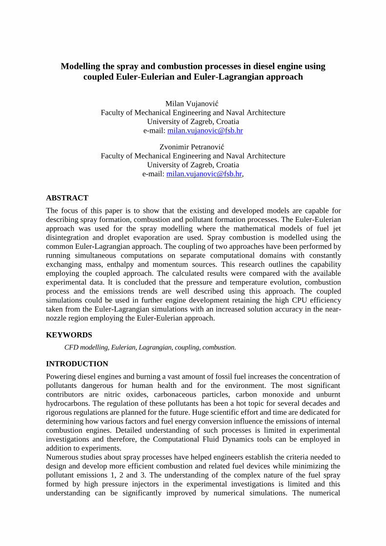
An outline of the spray region of the computational mesh is given in Figure 4. The conical mesh
consisted of 11760 control volumes. It was refined toward the spray inlet and the symmetry
axis. The diesel fuel was injected by the nozzle with an orifice diameter of 137 μ m into the
cylinder. Injection starts near the end of the compression stroke at 703.4 deg CA and finishes
at 738.2 deg CA.
Figure 4. Spray boundary conditions
The Eulerian multiphase results were generated using six phases total, one gaseous phase, four
droplet phases, and one bulk liquid phase. All phases were treated as interpenetrating multi-
fluids represented by their volume fractions. The gas phase was treated as the primary phase,
while the spray droplets were treated as the secondary phases. The droplets were classified into
different size classes by volume fractions and diameters. The size class diameters are 5, 10, 20
and 40 μ m for the droplet phases and the nozzle diameter of 137 μ m was assigned to the bulk
liquid phase. The mesh dependency of the Euler Eulerian and Euler Lagrangian simulation is
mentioned in [24], [25].
The initial conditions used for engine calculations are taken from [30]. The pressure at the start
of simulation (630 deg CA) was set to 0.45 MPa, temperature to 430 K. The cylinder was filled
with air initialised with turbulent kinetic energy of 50 m2/s2 and turbulent length scale of 0.001
m. The wall boundary selections were initialized with the same temperature as the in-cylinder
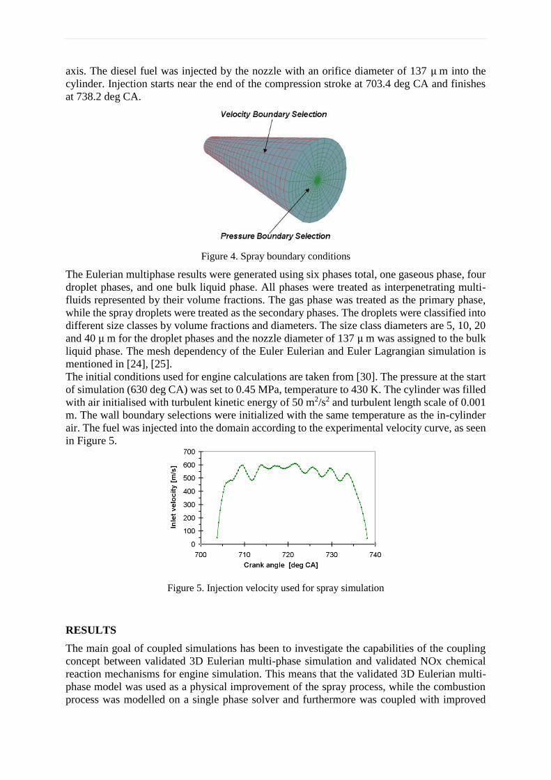
air. The fuel was injected into the domain according to the experimental velocity curve, as seen
in Figure 5.
Figure 5. Injection velocity used for spray simulation
RESULTS
The main goal of coupled simulations has been to investigate the capabilities of the coupling
concept between validated 3D Eulerian multi-phase simulation and validated NOx chemical
reaction mechanisms for engine simulation. This means that the validated 3D Eulerian multi-
phase model was used as a physical improvement of the spray process, while the combustion
process was modelled on a single phase solver and furthermore was coupled with improved

NOx reaction mechanisms [25], [23] and [30]. Two types of coupled simulations were
conducted in this work: swirl and non-swirl engine simulations. Two different cutting-planes
are used to present the simulation results as shown in Figure 5.
Figure 5. Cutting planes used for visualisation of simulation results
The gas phase velocity field is shown for 720 deg CA in Figure 6. As can be seen, the maximum
velocity is higher at the Eulerian spray domain than at the engine domain due to better mesh
resolution. In the spray simulation a significant volume fraction of the liquid phases occupies
the control volumes in a region near the nozzle, whilst in the engine simulations there is only
the gas phase. The plots also show good agreement of the gas flow field between two codes,
indicating that the gas flow field of the engine simulation was well mapped to the surface
boundaries of the spray client. In another direction, source terms resulting from spray
simulation were mapped to the engine client. Adequate source mapping can be seen in Figure
6. Overall, it can be said that velocity was resolved more accurately in the spray simulation due
to much finer mesh resolution, and the momentum exchange between the liquid and gaseous
phases calculated by spray code were well mapped to the engine simulation, providing a more
accurate flow field.

Figure 6. Gas velocity of the spray and engine code at 720 deg CA
Throughout the simulation the spray droplets disappear due to the evaporation process.
The heat arrives at the droplets from the ambient gas by conduction and convection, producing
the fuel vapor that leaves into the gas by convection and diffusion. Figure 7 shows a comparison
of the fuel vapor mass fraction between spray and engine code. As can be seen, the spray and
the engine fuel vapor results exhibit very similar trends and good agreement in the overlapping
region. One can observe a difference between the swirl and non-swirl simulation. The swirl
motion in the cylinder calculated by engine code impacts the spray simulation, and as can be
seen, the fuel vapor is deviated. This confirms that the gas flow field is well calculated and the
transfer of boundary condition values and source terms between the two simulations is good.
Figure 7. Fuel vapor of the spray and engine code at 720 deg CA
Figure 8 show the gas temperature distribution and nitrogen oxide (NO) mass fraction
distribution of the swirl and non-swirl engine simulations. The regions of NO can be examined
by looking at contours of NO and temperature. The formation of NO in the combustion
processes in engine simulations was predicted using reduced chemical reaction mechanisms
described in [23] and [30]. The used nitrogen scheme was based only on thermal NO formed
by oxidation of atmospheric nitrogen in a fuel-lean environment. Prompt NO was neglected
since this mechanism contributes only a minor part of the total NO in diesel engine.
The thermal NO mechanism arises from the thermal dissociation and subsequent reaction of
nitrogen and oxygen molecules in combustion air at relatively high temperatures. It is extremely
sensitive to the temperature and it is produced only in very hot products regions. Figure 8 shows
a comparison of NO mass fraction distribution with the temperature distribution, indicating that
NO occurs wherever there is high temperature.

Figure 8. Temperature and NO distribution at 720 deg. CA - side view
The transition from the Eulerian to the Lagrangian approach is presented on the Figure 9.
Figure 9. DDM parcels produced in the engine domain
As it is visible on the upper figure, after the liquid phase reaches the end of the Eulerian spray
domain the Lagrangian parcels are introduced. The mass, momentum and enthalpy source terms
are transferred to the Lagrangian engine simulation.
CONCLUSION
To demonstrate the capability of the coupling concept, an integrated simulation approach was
applied for calculation of the real internal combustion engine. An integrated simulation
approach was based on the idea of coupling two different simulations, the Euler-Eulerian
multiphase spray calculation performed only close to the nozzle in the dense spray region with
the single-phase engine calculation applying DDM and the NOx chemical reaction mechanisms
in the whole computational domain. The Eulerian multiphase spray simulation was performed
on a separate, fine mesh, while the single-phase engine simulation was performed on coarser
mesh, presenting the whole domain and arbitrarily overlapping the spray mesh. These
simulations were coupled and performed simultaneously to take advantage of the capabilities
inherent in both simulations. The flow field of the engine code calculations were used as
boundary condition values for the Eulerian multiphase spray code calculation, and the source
terms of the Eulerian multiphase spray code calculation were transferred to the gas phase

calculation of the engine code. The simulation results indicate that the coupling concept works
well, allowing an efficient data transfer between the Eulerian multiphase spray and single-phase
engine simulation. However, the time costs of the coupled simulation can be up to several time
higher than simulations employing the Eulerian-Lagrangian approach only. It is important to
note that further improvements can be made by implementation of the combustion process in
the Eulerian multiphase domain, including the transfer of energy and vapour sources from the
single-phase engine code to the Eulerian multiphase code. An integrated simulation method
presented in this work can be improved by coupling with nozzle flow simulation, taking into
account the influences from nozzle flow turbulence and cavitation dynamics on the primary
break-up of the liquid fuel jet. It can be stated that the presented simulation methods can serve
as an advanced tool to analyse and improve understanding of turbulent reacting multiphase flow
in real combustion configurations. This approach can be used to describe the high pressure
dense and dispersed liquid fuel spray behaviour and NOx formation, resulting in a better
description of the fuel-air mixing process and the pollutant formation process, which are crucial
issues to ensure better combustion efficiency and to reduce emission pollutants in modern
combustion systems.
REFERENCES
1. Choi CY, Reitz RD. An experimental study on the effects of oxygenated fuel blends and
multiple injection strategies on DI diesel engine emissions. Fuel 1999;78:1303–17.
doi:10.1016/S0016-2361(99)00058-7.
2. Kong S-C, Reitz RD. Application of detailed chemistry and CFD for predicting direct
injection HCCI engine combustion and emissions. Proc Combust Inst 2002;29:663–9.
doi:10.1016/S1540-7489(02)80085-2.
3. Saario A, Rebola A, Coelho P, Costa M, Oksanen A. Heavy fuel oil combustion in a
cylindrical laboratory furnace: measurements and modeling. Fuel 2005;84:359–69.
doi:10.1016/j.fuel.2004.10.002.
4. Dukowicz JK. A particle-fluid numerical model for liquid sprays. J Comput Phys
1980;35:229–53. doi:10.1016/0021-9991(80)90087-X.
5. Gouesbet G, Berlemont A. Eulerian and Lagrangian approaches for predicting the behaviour
of discrete particles in turbulent flows. Prog Energy Combust Sci 1999;25:133–59.
doi:10.1016/S0360-1285(98)00018-5.
6. Loth E. Numerical approaches for motion of dispersed particles, droplets and bubbles. Prog
Energy Combust Sci 2000;26:161–223. doi:10.1016/S0360-1285(99)00013-1.
7. Chen X-Q, Pereira JCF. Stochastic-probabilistic efficiency enhanced dispersion modeling of
turbulent polydispersed sprays. J Propuls Power 1996;12:760–9. doi:10.2514/3.24099.
8. Iyer V, Abraham J. Penetration and Dispersion of Transient Gas Jets and Sprays. Combust
Sci Technol 1997;130:315–34. doi:10.1080/00102209708935747.
9. Mikulč ić H, Vujanović M, Fidaros DK, Priesching P, Minicć I, Tatschl R, et al. The
application of CFD modelling to support the reduction of CO2 emissions in cement industry.
Energy 2012;45:464–73. http://dx.doi.org/10.1016/ j.energy.2012.04.030.
10. Hallmann M, Scheurlen M, Wittig S. Computation of Turbulent Evaporating Sprays: Eulerian
Versus Lagrangian Approach. J Eng Gas Turbines Power 1995;117:112.
doi:10.1115/1.2812758.
11. Baleta J, Vujanovic´ M, Pachler K, Duic´ N. Numerical modeling of urea water based
selective catalytic reduction for mitigation of NOx from transport sector. J Clean Prod 2014.
http://dx.doi.org/10.1016/j.jclepro.2014.06.042.
12. Harlow FH, Amsden AA. Numerical calculation of multiphase fluid flow. J Comput Phys
1975;17:19–52. doi:10.1016/0021-9991(75)90061-3.
13. Iyer VA, Abraham J, Magi V. Exploring injected droplet size effects on steady liquid
penetration in a Diesel spray with a two-fluid model. Int J Heat Mass Transf 2002;45:519–31.
doi:10.1016/S0017-9310(01)00168-5.
14. Issa R., Oliveira P. Numerical prediction of phase separation in two-phase flow through T-
junctions. Comput Fluids 1994;23:347–72. doi:10.1016/0045-7930(94)90045-0.
15. Behzadi A, Issa RI, Rusche H. Modelling of dispersed bubble and droplet flow at high phase
fractions. Chem Eng Sci 2004;59:759–70. doi:10.1016/j.ces.2003.11.018.
16. Gosman AD, Lekakou C, Politis S, Issa RI, Looney MK. Multidimensional modeling of
turbulent two-phase flows in stirred vessels. AIChE J 1992;38:1946–56.
http://dx.doi.org/10.1002/aic.690381210.
17. Riber E, Moreau M, Simonin O, Cuenot B. Development of Euler–Euler LES method for gas-
particle turbulent jet flow. In: Proceedings of ASME Fluids Engineering Division Summer
Meeting; 2006. p. 1663–1672.
18. Petranović , Zvonimir; Edelbauer, Wilfried; Vujanović , Milan; Duić , Neven. Validation of
Eulerian-Eulerian Approach for Diesel Sprays, and 3D Coupling with Lagrangian Spray
Approach // Proceedings of the 25th European Conference on Liquid Atomization and Spray
Systems (ILASS-Europe), 2013
19. Petranović , Zvonimir; Edelbauer, Wilfried; Vujanović , Milan; Duić , Neven. The O’Rourke
droplet collision model for the Euler-Eulerian framework // Proceedings of the 26th European
Conference on Liquid Atomization and Spray Systems, 2014
20. Vujanović , Milan; Petranović , Zvonimir; Duić , Neven. Modelling of Hot Diesel Injection
Process Using Eulerian Multiphase Method // Digital Proceedings of 1st South East European
Conference on Sustainable Development of Energy, Water and Environment Systems - SEE
SDEWES Ohrid 2014
21. W. Edelbauer, D. Suzzi, P. Sampl, R. Tatschl, C. Krueger, B. Weigand, New Concept for On-
line Coupling of 3D Eulerian and Lagrangian Spray Approaches in Engine Simulations, Proc.
10th International Conference on Liquid Atomization and Spray Systems, 2006
22. W. Edelbauer, (2011) Coupling od 3D Eulerian and Lagrangian Spray Approaches in
Industrial Combustion Engine Simulations, 24th European Conference on Liquid Atomization
and Spray Systems ILASS, Estoril, Portugal.
23. AVL AST, FIRE manual version 2014, AVL List GmbH, 2014
24. Petranović Z, Vujanović M, Duić N. Towards a more sustainable transport sector by
numerically simulating fuel spray and pollutant formation in diesel engines. J Clean Prod
2014. doi:10.1016/j.jclepro.2014.09.004.
25. Vujanović M, Petranović Z, Edelbauer W, Baleta J, Duić N. Numerical modelling of diesel
spray using the Eulerian multiphase approach. Energy Convers Manag 2015.
doi:10.1016/j.enconman.2015.03.040.
26. Mikulč ić H, Vujanović M, Fidaros DK, Priesching P, Minić I, Tatschl R, et al. The
application of CFD modelling to support the reduction of CO2 emissions in cement industry.
Energy 2012;45:464–73. doi:10.1016/j.energy.2012.04.030.
27. Petranović Z. Matematič ko modeliranje procesa spreja, Master Thesis, University of
Zagreb, Faculty of Mechanical Engineering and Naval architecture.
28. D. B. Spalding, 13th symposium on Combustion, The combustion Instituite, 1970, p. 649
29. B. F. Magnussen and B. H. Hjertager, On mathematical models of turbulent combustion with
special emphasis on soot formation and combustion, In 16th Symp. (Int'l.) on Combustion,
The Combustion Institute, Pittsburgh, PA, 1976, pp. 719-729
30. Vujanović M., 2010. Numerical Modelling of Multiphase Flow in Combustion of Liquid
Fuel, Doctoral Thesis, University of Zagreb, Faculty of Mechanical Engineering and Naval
architecture.