model xl1236 programming instructions 'notes' …library.ademconet.com/mwt/fs2/6/2302.pdfi...
TRANSCRIPT
c . ‘.
. .
‘
XL-1236 Programming Instructions
_. Fire Burglcrry Instruments, Inc. q
1 LJINC ,I 50 Engineers Road. Hauppauge, New‘York 11788 . (800) 6454430
COMPUTER PART NO. I-2278 JT.li,Y.--36 ' ,‘*’
-

: ’ .I.’ .
*: 3 l .
:
. , many of the panels functions including zone types and operations, audible or silent outputs, etc. are prom programmable. Therefore, it is imperative that these instructions are read
0 and followed very carefully. Many of the options available will require programming in
. several different locations of different fields. It is advisable to utilize the BLANK PROGRAMMING SHEET MARKED WITH -LOCATIONS (Ll, L2, etc.) to write out the entire program before attempting to actually program. The first and MOST IMPORTANT decision which mu&t be made prior to programming is what each of the 12 general purpose zones are planned to be. There are several options such as 24 HR ALARM ZONES, 24 HR TROUBLE ZONES, or CONTROLLED ZONES (Delay, Instant, Interior).
110 Programmer Switch Setting:
MODE SWITCH QUADRANT SW. 8
North South North South
North North
North North
QUADRANT SW. 7
South North
South
North ,
QUADRANT + SELECTED
1 2
3
4
R96 Quad Selection Jumper Setting 1
2 Quad Program 3 or 4 Quad Program Quad 1 & 2 Connected
Quad 3 dc 4 cut Connected
.
it will be necessary to program on at LEAST (2) quadrants of the prom chip for operation of this system. Either quadrants one and two or quadrants three and four may be used. The condition of resistor R96 in the XL1,236 system dictates which .two quadrants of the prom will be used. It may be necessary to do a four (4) quadrant program. on installations which require advanced communicator features. The charts above explain the appropriate 110 switch settings versus the correct condi- tion of the R96 resistor in the system.
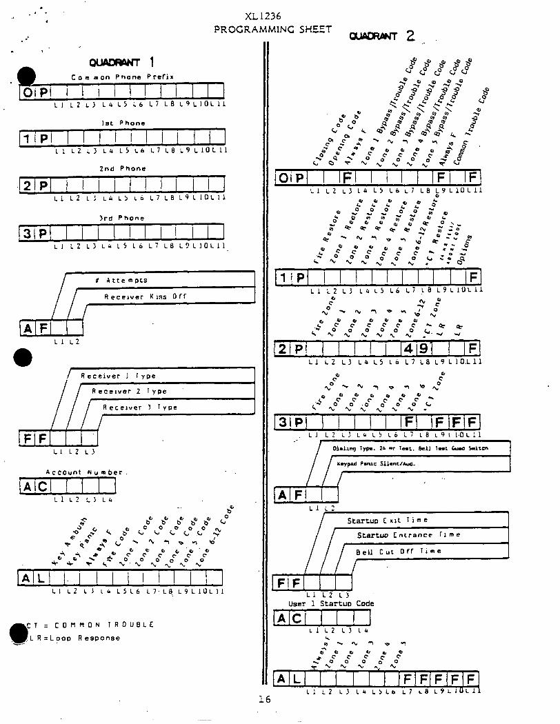
THIS INSTRUCTION MANUAL IS DESIGNED TO ACCOMPLISH WRITING OUT THE XL1236 PROM PROGRAMMING SHEET1-2277 ON PAGE 15. CONTROL PANEL HOOKUP AND WIRING INFORMATJON CAN BE FOUND IN INSTALLATION INSTRUCTION I 2276
STEP 1: QUADRANT 1, op FIELD
This OP FIELD locations Ll-Lll can be used to program a common telephone number prefix. (example: 9, 1,800 etc.) All numbers pro- grammed here will be dialed prior to any and all receiver telephone numbers programmed.
STEP 2: 1P FIELD : LOCATIONS Ll-Lll in this field must be used, to program the telephone number of the first receiver. As many as eleven (11) digits can be programmed.
2

STEP 3: 2P FIELD
LOCATIONS L I-11 1 can be used to program the telephone number of the second receiver. As many as eleven (11) digits can be programmed. If there is not a second receiver, leave this field blank on the program sheet.
STEP 4: 3P FIELD
LOCATIONS Ll-Lll can be used to program the telephone number of receiver three. As many as eleven (11) digits can be programmed. If there is not a third receiver, leave this field blank on the program sheet.
STEP 5: AF FIELD
THE FIRST LOCATION of this AF field marked 11 is used to program the number, of attempts the XL1236 system should make in the event the receiver or receivers are busy. Select a digit from the following chart as desired.
# OF ATTEMPTS DlGIT il/ OF ATTEMPTS DIGIT # OF ATTEMPTS DlGIT
1 1 7 7 13 D I 2 2 8 8 14 E 3 3 9 9 15 A 4 4 10 0 Unlimited F / I
I 5 6 6 5 12 11 B C 4
THE SECOND LOCATION of this AF field marked L2 is used to deter- mine two (2) things concerning the receiver format. The first thing is whether the XL1236 system should transmit all its data to just the first receiver (ANY ONE RECEIVER) or will it be necessary to transmit to. x.., ALL RECEIVERS assuming there is more than one telephone number
. . programmed. The second thing which must be determlned in this location is whether all transmissions to the receivers should be .PRIORITY REPORT, -’ STANDARD FORMAT, OR EXTENDED FORMAT. Priority report means that if more than one circuit is tripped within the same phone call to the central office, ONLY THE HIGHEST PRIORITY circuit will be reported (example: Fire and Burglary trip, only Fire is transmitted). Priority report should be programmed for receivers which can not handle multiple codes within the same phone call. STANDARD FORMAT means all circuits which are tripped within the same phone call will be reported to the central office. EXTENDED FORMAT is similar to the standard format in that all circuits tripped will be transmitted to the central office, however, extended format involves an advanced form of dialer communication. EXTENDED FORMAT is explained in the XLI%i@&EWANCED COMMUNICATION MANUAL. Do not select this format withobt a full understanding.

SELECT A DIGIT FROM THE FOLiOWING CHART FOR THE OPTIONS DESIRED IN THIS L2 LOCATION.
, , DIGIT FUNCTIONS
0 any one receiver, priority report
I any one receiver, extended format
2 any one receiver, standard format
4 all receivers , priority report
5 all receivers, extended format
6 all receivers , standard format l 4
STEP 6: FF FIELD
Select a digit from the following chart for each of the receiver types per each telephone number programmed. 11 location of this field corresponds to the receiver at phone number one (1). 12 .and L3 correspond to the re- ceivers at phone numbers (2) and (3) respectively.. If only one receiver is being used, leave locations L2 and 13 blank. NOTE: ALL RECEIVERS MUST HAVE A KISSOFF TONE.
~DIGIT I RECEIVER TYPE I L
0 1 FBI, Radionics 2300hz, 2Opps w/parity
1 FBI, Franklin, Sescoa, DCI, Radionics, 2300hz, 2Opps, Osborne Hof.Quika. 2 FBI, Radionics 1400hz, 2Opps w/parity
3 FBI, Adcor CDRSO, Radionics 1400hz, 2Opps.
1 FBI, Ademco I 7 FBI, Silent Knight (slow)
8 FBI, Radionics 2300hz, 4Opps w/parity
7 ‘rh:..;. . 2y..-.
STEP 7: AC FIELD _1
a,
LOCATIONS Ll-L4 mu& be used to program a three (3) or four (4) digit SUBSCRIBER ACCOUNT CODE. A Four digit account code can be used ONLY if the receiver is capable of handling it.
, . i .
.
. : ,
.@
STEP 8: AL FI=j D -a-
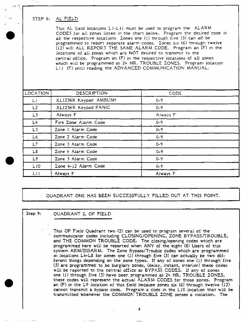
This AL field locations Ll-Lll must be used to program the ALARM CODES for all zones listed in the chart below. Program the desired code in all the respective locations iones one (I) through five (5) can all be programmed to report separate alarm codes. Zones SI>; (6) through twelve (ii’) will ALL REPORT THE SAME ALARM CODE. Program an (F) in the locations of all zones which are NOT desired to transmit to the central office. Program an (F) in the respective locations of all zones which will be programmed as 24 HR. TROUBLE ZONES. Program location Lll (F) until reading the ADVANCED COMMUNICATION MANUAL.
LOCATION DESCRIPTION CODE 11 XL1236R Keypad AMBUSH o-9
L2 XL1236R Keypad PANIC
L3 Always F o-9 Always F
I L4 Fire Zone Alarm Code o-9
I L5 1 Zone 1 Alarm Code I o-9
L6
L7
18
Zone 2 Alarm Code
Zone 3 Alarm Code
Zone 4 Alarm Code
o-9 o-9
o-9 I 19 1 Zone 5 Alarm Code I o-9
LlO Zone 6-12 Alarm Code o-9 Lll t Always F Always F
,
QUADRANT ONE HAS BEEN SUCCESSFULLY FILLED OUT AT THIS POINT. c
Step 9: QUADRANT 2, OP FIELD
This OP Field Quadrant two (2) can be used to program several of the ’ communicator codes including CLOSING/OPENING, ZONE BYPASS/TROUBLE,
and THE COMMON TROUBLE CODE. The closing/opening codes which are programmed here will be reported when ANY of the eight (8) Users of this system ARM/DISARM. The Zone Bypass/Trouble codes which are programmed in locations L4-L8 for zones one (1) through five (5) can actually be two dif- ferent things depending on the zone types. If any of zones one (1) through five (5) are programmed to be burglary zones, (delay, instant, interior) these codes will be reported to the central office as BYPASS CODES. If any of zones one (1) through five (5) have been programmed as 24 HR. TROUBLE ZONES, these codes will represent the actual ALARM CODES for those zones. Program an (F) in the L9 location of this field because zones six (6) through twelve (12) cannot transmit a bypass code. Program a code in the LlO location that will be transmitted whenever the COMMON TROUBLE ZONE senses a violation. The
4
. .: . . . . .
.a
. -
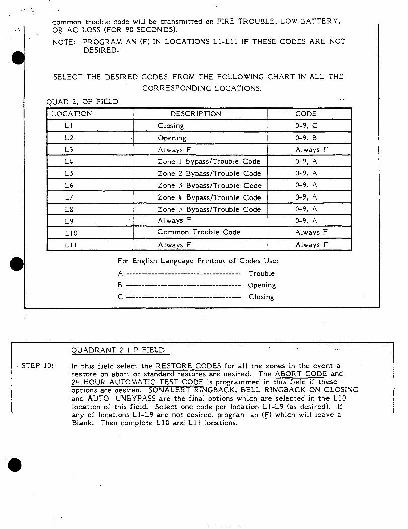
common trouble code will be transmitted on FIRE TROUBLE, LOW BATTERY, 08 AC LOSS (FOR 90 SECONDS).
NOTE: PROGRAM AN (F) IN LOCATIONS 11-111 IF THESE CODES ARE NOT DESIRED.
SELECT THE DESIRED CODES FROM THE FOLLOWING CHART IN ALL THE CORRESPONDING LOCATIONS.
QUAD 2, OP FIELD .-
I Always F Always F I
For English Language Printout of Codes Use:
A ____ -_- ___________ ---- ______________ Trouble
B ___-_______-______-________________ Opening
C i,,,-, ____ -_-_--.---.. ______ -_--_--_ Closing
QUADRANT 2 1 P FIELD
STEP 10: In this field select the RESTORE CODES for all the zones in the event a restore on abort or standard restores are desired. The ABORT CODE and 24 HOUR AUTOMATIC TEST CODE is programmed in this field if these options are desired. SONALERT RINGBACK, BELL RINGBACK ON CLOSING and AUTO UNBYPASS are the final options which are selected in the 110 location of this field. Select one code per location 11-19 (as desired). If any of locations Ll-19 are not desired, program an (F) which will leave a Blank, Then complete 110 and 111 locations. -
., _. _ _---- -.. * I
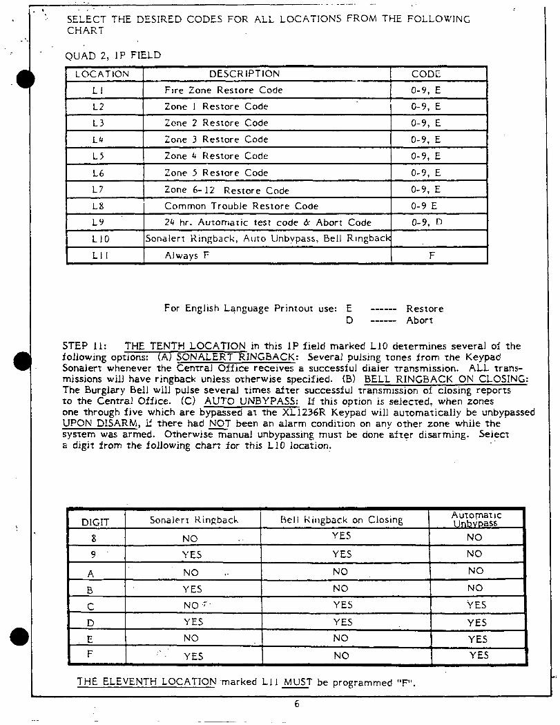
i : SE&T THE DESIRED CODES FOR ALL LOCATIONS FROM THE FOLLOWING
CHART
QUAD 2, 1P FIELD
LOCATION DESCRIPTION
LI Fire Zone Restore Code
12 Zone 1 Restore Code
CODE
O-9, E O-9, E
13 fcne 2 Restore Code O-9, E F 14 Zone 3 Restore Code O-9, E
LS Zone 4 Restore Code O-9, E
16 Zone 3 Restore Code O-9, E
17 Zone 6-12 Restore Code O-9, E & I 18 i Common Trouble Restore Code I O-9 E I T
LY 24 hr. Automatic test code & Abort Code o-9, D
L10 Sonalert Ringback, Auto Unbypass, Bell Rlngback & I LII I Always F
For English Language Printout use: E ------ Restore D ------ Abort
STEP 11: THE TENTH LOCATION in this 1P field marked 110 determines several of the following options: (A) SONALERT RINGBACK: Several pulsing tones from the Keypad Sonalert whenever the Central Office receives a successful dialer transmission. ALL trans- missions will have ringback unless orherwise specified. (B) BELL RINGBACK ON CLOSING: The Burglary Bell will pulse several times after successful transmission of closing reporrs to the Central Office. CC> AUTO UNBYPASS: If this option is selected, when zones one through five which are bypassed at the XL1236R Keypad will automatically be unbypassed UPON DISARM, if there had NOT been an alarm condition on any other zone while the system was armed. Otherwisemanual unbypassing must be done after disarming. Seiect a digit from the following chart for this 110 location. _-
DIGIT Sonalert Kingbach Rtll Kingback on Closing
8 NO . . YES
‘9 YES YES
A NO 4. NO
B YES NO
C NO .F-. YES
D YES YES
E NO NO F .; _ I YES NO
THE ELEVENTH LOCATION .marked Lll MUST be programmed “F”.
Automatic Unbvoass
NO
NO
NO
NO
i’ES
YES
YES YES
6
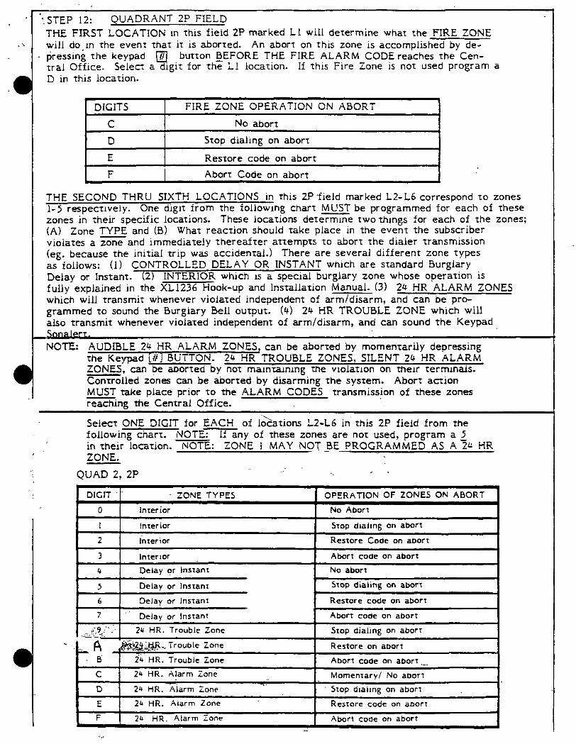
. :STEP 12: QUADRANT 2P FIELD THE FIRST LOCATION in this field 2P marked Ll will determine what the FIRE ZONE will do,in the event that it is aborted. An abort on this zone is accomplished by de-
. pressing the keypad q button BEFORE THE FIRE ALARM CODE reaches the Cen- tral Office. Select a digit for the Ll location. If this Fire Zone is not used program a D in this location.
DIGITS CT
) FIRE ZONE OPERATION ON ABORT I No abort
D ! Stop dialing on abort
E Restore code on abort F Abort Code on abort
THE SECOND THRU SIXTH LOCATIONS in this 2P*field marked L2-L6 correspond to zones l-5 respectively. One digit from the following chart MUST be programmed for each of these zones in their specific locations. These locations dete= two things for each of the zones; (A) Zone TYPE and (B) What reaction should take place in the event the subscriber violates a zone and immediately thereafter attempts to abort the dialer transmission (eg. because the initial trip was accidental.) There are several different zone types as follows: (1) CONTROLLED DELAY OR INSTANT which are standard Burglary Delay or Instant. (2) INTERIOR which IS a special burglary zone whose operation is fully explained in the XL1236 Hook-up and installation Manual. (3) 24 HR ALARM ZONES which will transmit whenever violated independent of arm/disarm, and can be pro- grammed to sound the Burglary Bell output. (4) 24 HR TROUBLE ZONE which will also transmit whenever violated independent of arm/disarm, and can sound the Keypad
.NOTE: AUDIBLE 24 HR ALARM ZONES, can be aborted by momentarily depressing the Keypad [/I! BUTTON. 24 HR TROUBLE ZONES, SILENT 24 HR ALARM ZONES, can be aborted by not maintaining the violation on their terminals. Controlled zones can be aborted by disarming the system. Abort action MUST take place prior to the ALARM CODES transmission of these zones reaching the Central Office.
Select ONE DIGIT for EACH of lo>ations L2-L6 in’ this 2P field from the following chart. NOTE: If any of these zones are not used, program a 2 I
, in their location. NOTE: ZONE 1 MAY NOT BE PROGRAMMED AS A 24 HR -- ZONE.
. QUAD 2, 2P _- ‘_ _ .
ZONE TYPES OPERATION OF ZONES ON ABORT
0 Inter ior No Aborr
1 Inter ior Stop dlalmg on abort I
2 lnrerior Restore Code on aborr
3 lnterror Abort code on abort
4 Delay or lnsranr No abort
5 Delay or Instant Stop dialing on abort i
6 Delay or Instant Restore code on abort
, .‘. I Delay or Instant Abort code on abort .- . [ ..&?_“ J, 1 24 HR. Trouble Zone Stop dialing on abort
“a &&2$2k#... Trouble Zone Restore on abort _.
6 1 24 HR. Trouble Zone 1 Abort code on abort _~ I
C 24 HR. Alarm Zone Momentary/ No aborr
D 24 HR. Alarm Zone -. _
Stop dlailng on aborr
E 24 HR. Alarm Zone Restore code on aoorr I
F 2L HR. Alarm Zone Abort code on abort
. . . .
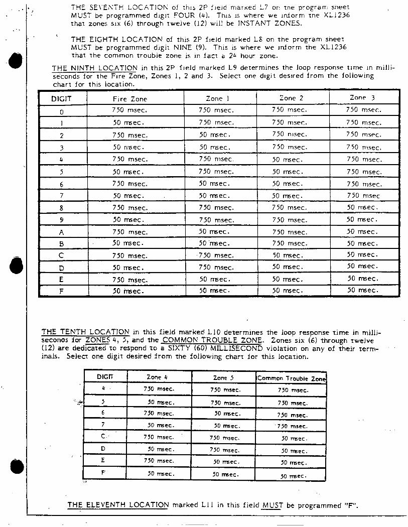
THE SE\‘EKTH LOCATION of tius 2P f~elti marKed L7 or: tne program sheet MUST be programmed digir FOUR (4). This IS where we inform the XL1236 that zones six (6) through twelve (12) will be INSTANT ZONES.
THE EIGHTH LOCATION of this 2P field marked LS on the program sheer MUST be programmed digit NINE (9). This is where we inform the XL1236 that the common trouble zone is in fact a 24 hour zone.
THE NINTH LOCATION in this 2P field marked 19 determines the loop response time in milli- seconds for the Fire Zone, Zones 1, 2 and 3. Select one digit desired from the following chart for this location.
THE TENTH LOCATION in this field marked LlO determines the loop response time in milli- seconds for ZONES 4, 5, and the COMMON TROUBLE ZONE. Zones six (6) through twelve (12) are dedicated to respond to a SIXTY (60) MILLISECOND violation on any of their term- inals. Select one digit desired from the following chart for this location.
THE ELEVENTH LOCATION marked Ll 1 in this field MUST be programmed “F”.
. .? .
i . .
l 4
a
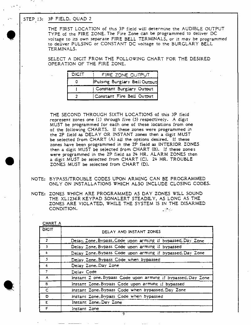
STEPJ3: 3P FIELD, QUAD 2
THE FIRST LOCATION of this 3P field will determine the AUDIBLE OUTPUT TYPE of the FIRE ZONE. The Fire Zone can be programmed to deliver DC voltage to its own separate FIRE BELL TERMINALS, or it may be programmed to deliver PULSING or CONSTANT DC voltage to the BURGLARY BELL TERMINALS.
SELECT A DIGIT FROM THE FOLLOWING CHART FOR THE DESIRED OPERATION OF THE FIRE ZONE.
1 DIGIT 1 FiRE ZONE OUTPUT 1
I 0 IPulsIng Burglary Bell Out~ur(
1 1 Constant Burglary Output 2 I Constant Fire Bell Ourout
THE SECOND THROUGH SIXTH LOCATIONS of this 3P field represenr zones one (1) through five (5) respectively. A digir MUST be programmed for each one of these locations from one of the following CHARTS. If these zones were programmed in the 2P field as DELAY OR INSTANT zones then a digit MUST be selected from CHART (A) all the options desired. If these zones have been programmed in the 2P field as INTERIOR ZONES then a digit MUST be selected from CHART (B). If these zones were programmed in the 2P field as 24 HR. ALARM ZONES then a digit MUST be selected from CHART (Cl. 24 HR. TROUBLE ZONES MUST be selected from CHART (D).
NOTE: BYPASS/TROUBLE CODES UPON ARMING CAN BE PROGRAMMED ONLY ON INSTALLATIONS WHICH ALSO INCLUDE CLOSING CODES.
NOTE: ZONES WHICH ARE PROGRAMMED AS DAY ZONES WILL SOUND THE XL1236R KEYPAD SONALERT STEADILY, AS LONG AS THE ZONES ARE VIOLATED, WHILE THE SYSTEM IS IN THE DISARMED CONDITION. .<r-.. .._ . .
CHART A
DIGIT I I
DELAY AND INSTANT ZONES I
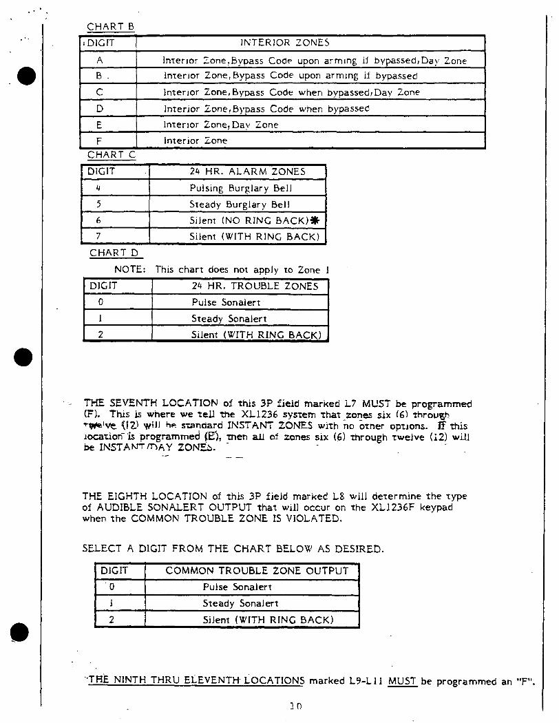
CHART B ~;DJGJT I INTERIOR ZONES 1
A interior Zone,Bypass Code upon arming if bypassed,Day Zone B interior Zone,Bypass Code upon arming if bypassed
C interior Zone, Bypass Code when bypassed, Day Zone
D Interior Zone! Bypass Code when bypassed
E interior Zone, Dav Zone
F Interior Zone CHART C
t DlGJT I 24 HR. ALARM ZONES I
CHART D NOTE: This chart does not apply to Zone 1
+ DIGIT 24 HR. TROUBLE ZONES
0 Pulse Sonalert 1 Steady Sonalert 2 Silent (WITH RING BACK)
THE SEVENTH LOCATION of this 3P field marked 17 MUST be programmed (FL This is where we tell the XL1236 sysrem That-zones six (61 rhroqh ft#elve {lZ\ will h e standard INSTANT ZONES with no omer options. If this rocariori “rs programmed (E); men all of zones six (6) through Twelve (12) will be INSTAWfnAY tONI%. - -- -- -
THE EIGHTH LOCATION of this 3P field marked 18 will determine the type of AUDIBLE SONALERT OUTPUT that will occur on the XL1236F keypad when the COMMON TROUBLE ZONE IS VIOLATED.
SELECT A DIGIT FROM THE CHART BELOW AS DESIRED. .
DlGIT COMMON TROUBLE ZONE OUTPUT ‘0 Pulse Sonalert 1 Steady Sonaiert
2 Silent (WITH RING BACK)
‘.THE NINTH THRU EiEVENTH- LOCATIONS marked 19-L 11 MUST be programmed an “F”.

. ’ ,- STEP 14:
THE FIRST LOCATION of this AF field marked Ll can be programmed for several control panel options which are actually unrelated to each other, however, they all share this location. Option one is TOUCHTONE or ROTARY (PULSE) DIALING.
1 The second option is called BELL TEST. The BURGLARY B,ELL will ring momentarily when this system is armed. The third option is called 24 HR AUTOMATIC TEST CODE. If this option is selected the XL1236 will automatically transmit A TEST SIGNAL every 24 HOURS. The timer will be RESET every time there is ANY transmission to the central office from this system. The last option in this location is called QUAD SWITCHING. This option is necessary ONLY when the XL1236 is being programmed to do a FOUR QUADRANT program (example: open/close by user). DO NOT PROGRAM THIS OPTION UNTIL READING AND UNDERSTANDING THE ADVANCED COMMUNICATION .MANUAL.
SELECT A DIGIT FROM THE FOLLOWING CHART THAT REPRESENTS ALL THE OPTIONS DESIRED IN THIS Ll LOCATION.
DIGIT
0
1 2
3
I
FUNCTIONS
Touchtone dialing, quad switching, bell test, 24 Hr. auto test
Touchtone dialing, quad switching, bell test
Touchtone, quad switching, 24 hr. automatic test
Touchtone, quad switching 4 I Touchtone, Bell Test, 24 Hr. auto test I 5 Touch tone, Be II Test
6 Touchtone. 24 Hr. auto test
1
7 Touchtone dialing
8 Rotary dialing, quad switching, bell test, 24 Hr. auto test 9 Rotary, quad switching, bell test A Rotary, quad switching, 24 Hr. auto test B Rotary, quad switching
C Rotary, bell test, 24.Hr. auto test
D Rotary, bell test
E Rotary, 24 Hr. Auto Test F Rotarv Dlalina
THE SECOND LOCATION of this AF field marked L2 can be programmed-for’ .. several system options, which are unrelated to each other. The only relationship between the several options is that they are all programmed in this location.
The first oprion in this location regards XL 1236 KEYPAD PANIC’ which can be programmed either audible or silent. The second option is called OPENING CODE AFTER ALARM ONLY. This feature was designed into this system to be used on residential systems. The purpose of this option is to allow the XL1236 to report a RESTOR E CODE to the central office when this system is disarmed AFTER A BURGLARY ALARM has occurred. (The actual RESTORE CODE which will be reported must be programmed in QUAD Z OP FIELD, L2 LOCATION, called OPENING CODE.).
11
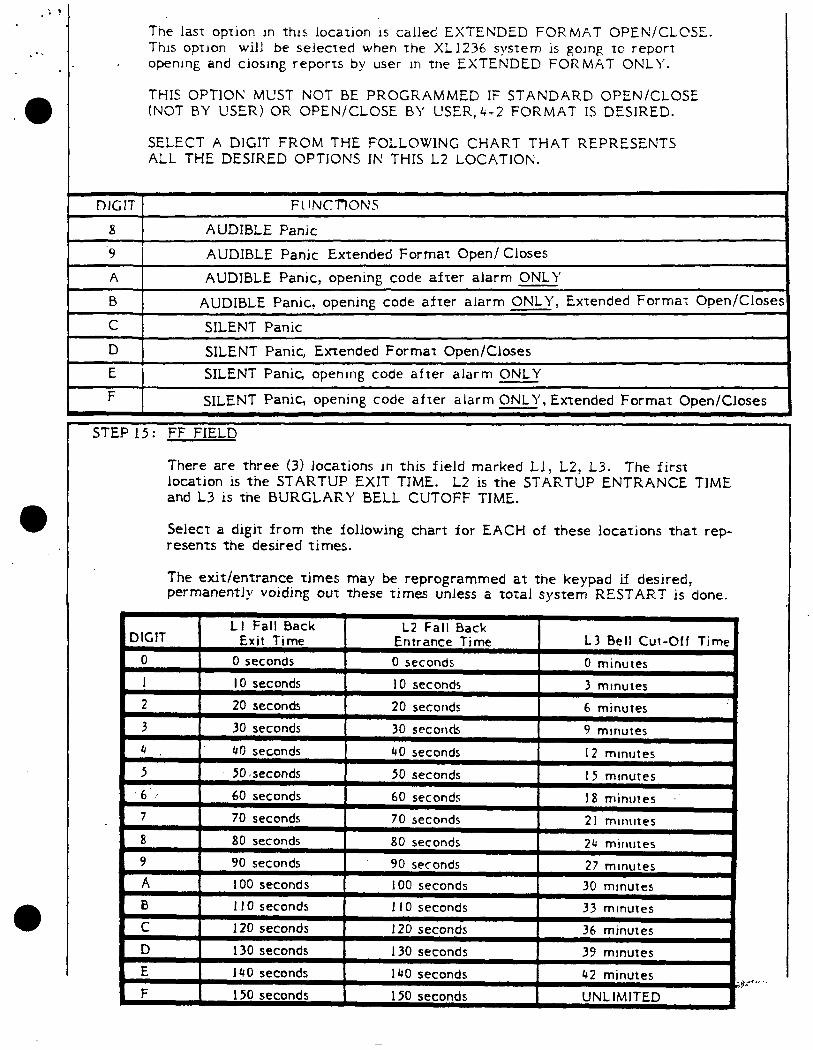
The last option in this iocation is called EXTENDED FORMAT OPEN/CLCSE. This option will be selected when the XL1236 system is going to report opening and ciosmg reports by user in the EXTENDED FORMAT ONLY.
THIS OPTlOti MUST NOT BE PROGRAMMED IF STANDARD OPEN/CLOSE (NOT BY USER) OR OPEN/CLOSE BY USER,&2 FORMAT IS DESIRED.
SELECT A DIGIT FROM THE FOLLOWING CHART THAT REPRESENTS ALL THE DESIRED OPTIONS IN THIS 12 LOCATION.
8 a
‘9 I
AUDIBLE Panic
AUDIBLE Panic Extended Format Open/ Closes A AUDIBLE Panic, opening code after alarm ONLY B
b AUDIBLE Panic, opening code after alarm ONLY, Extended Format Open/Closes
I 4
C SILENT Panic I I D 1 SILENT Panic, Extended Format Open/Closes I
I I
E SILENT Panic, openmg code after alarm ONLY
F SILENT Panic, opening code after alarm ONLY, Extended Format Open/Closes
STEP 15 : FF FIELD
There are three (3) locations in this field marked Ll, L2, L3. The first location is the STARTUP EXIT TIME. L2 is the STARTUP ENTRANCE TIME and L3 is the BURGLARY BELL CUTOFF TIME.
Select a digit from the following chart for EACH of these locations that rep- resents the desired times.
The exit/entrance times may be reprogrammed at the keypad if desired, permanently voiding out these times unless a total system RESTART is done.
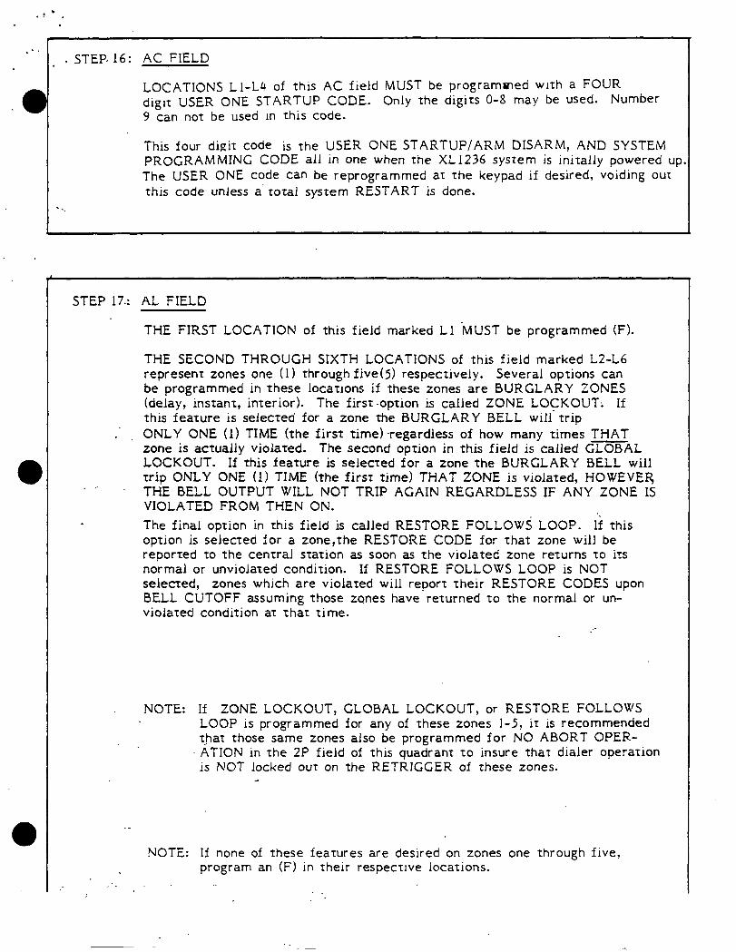
. ’ STEP. 16: AC FIELD
LOCATIONS 11-14 of this AC field MUST be programcned with a FOUR digit USER ONE STARTUP CODE. Only the digits O-8 may be used. Number 9 can not be used In this code.
This four digit code is the USER ONE STARTUP/ARM DISARM, AND SYSTEM PROGRAMMING CODE all in one when the XL1236 system is initally powered up The USER ONE code can be reprogrammed at the keypad if desired, voiding out this code unless a’ total system RESTART is done.
STEP 17.: AL FIELD
THE FIRST LOCATION of this field marked Ll -MUST be programmed (F).
THE SECOND THROUGH SIXTH LOCATIONS of this field marked L2-L6 represent zones one (1) through five(5) respectively. Several options can be programmed in these locations if these zones are BURGLARY ZONES (delay, instant, interior). The first .option is called ZONE LOCKOUT; If this feature is selecred for a zone the BURGLARY BELL will. trip
* ONLY ONE (1) TIME (the first time)-regardless of how many times THAT zone is actually violated. The second option in this field is called GLOBAL LOCKOUT. If this feature is selected for a zone the BURGLARY BELL will rrip ONLY ONE (1) TIME (the first time) THAT ZONE is violated, HOWEVER . .’ THE BELL OUTPUT WILL NOT TRIP AGAIN REGARDLESS IF ANY ZONE IS VIOLATED FROM THEN ON.
The final option in this field is called RESTORE FOLLOWS LOOP. If this option is selected for a zone,the RESTORE CODE for that zone will be reported to the central station as soon as the violated zone returns to its normal or unviolated condition. If RESTORE FOLLOWS LOOP is NOT selected, zones which are violated will report their RESTORE CODES upon BELL CUTOFF assuming those zones have returned to the normal or un- violated condition at that time.
NOTE: If ZONE LOCKOUT, GLOBAL LOCKOUT, or RESTORE FOLLOWS LOOP is programmed for any of these zones l-5, it is recommended t!at those same zones also be programmed for NO ABORT OPER- ATION in the 2P field of this quadrant to insure that dialer operation is NOT locked out on the RETRIGGER of these zones.
d
NOTE: If none of these features are desired on zones one through five, program an (F) in their respective locations.

‘INC CHART FOR EACH OF THESE SELECT A DIGIT FROM THE FOLLOW LOCATIONS LZ-16.
QUAD 2? AL FIELD
b
DIGJT FUNCTIONS
3 ‘Zone lockout
5 Global lockofl
7 Restore Follows Loop
B Restore Follows Loop, Zone lockout
D Restore Follows LOOD, Global lockout F None of the above.
THE SEVENTH (7) THROUGH ELEVENTH (11) LOCATIONS of this field marked 17-111 MUST be programmed (F).
STEP 18: The XL1236 PROGRAMMING SHEET has been successfully filled out at this point.
EXTENDED FORMAT OPEN/CLOSE BY USER AND 4+2 FORMAT can all be found in the ADVANCED COMMUNICATIONS MAN.UAL l-2266
Continue on the following page called PROPER PROM PROGRAMMING PROCEDURE for a step by step explanation to actually BURN the data entered here on the.XL1236 program sheet into the prom chip with the 1 iO/llOC programmer’.
AFTER THE PROM CHIP HAS BEEN SUCCESSFUiLY PROGRAMMED, MUST BE INSERTED INTO THE XL1236 SYSTEM BLUE DOT RIGHT
I’ T
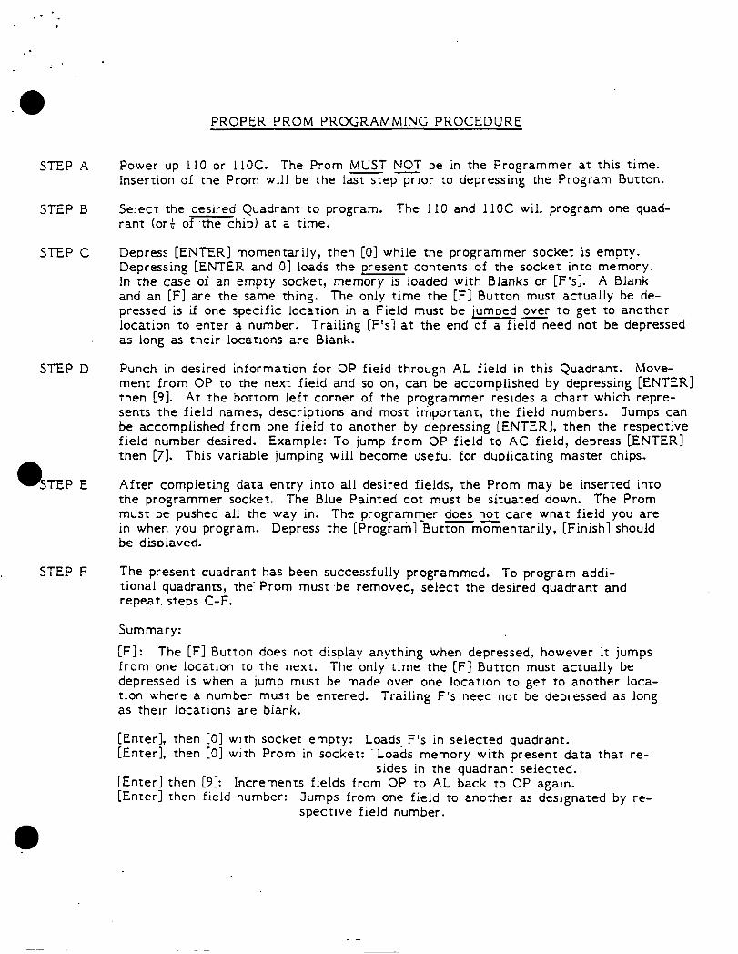
PROPER PROM PROGRAMMING PROCEDURE
STEP A Power up 110 or 11OC. The Prom [MUST NOT be in the Programmer at this time. -e Insertion of the Prom will be the last step prior to depressing the Program Button.
STEP B Select the desired Quadrant to program. Ihe 110 and 1lOC will program one quad- rant (ori of the chip) at a time.
STEP C Depress [ENTER] momentarily, then [Ol while the programmer socket is empty. Depressing [ENTER and 01 loads the present contents of the socket into memory. In the case of an empty socket, memory IS loaded with Blanks or [F’s]. A Blank and an [F] are the same thing. The only time the [Fl Button must actually be de- pressed is if one specific location in a Field must be jumoed over to get to another location to enter a number. Trailing [F’s] at the end of a fie=eed not be depressed as long as their locations are Blank.
STEP D Punch in desired information for OP field through -AL field in this Quadrant. Move- ment from OP to the next field and so on, can be accomplished by depressing [ENTER] then [9]. At the bottom left corner of the programmer resides a chart which repre- sents the field names, descriptions and most important, the field numbers. Jumps can be accomplished from one field to another by depressing [ENTER], then the respective field number desired. Example: To jump from OP field to AC field, depress CENTER] then [7]. This variable jumping will become useful for duplicating master chips.
After completing data entry into all desired fields, the Prom may be inserted into the programmer socket. The Blue Painted dot must be situated down. The Prom must be pushed all the way in. The programmer does not care what field you are in when you program. Depress the [Program] Buttonmomentarily, [Finish] should be disolaved.
STEP F The present quadrant has been successfully programmed. To program addi- tional quadrants, the. Prom must .be removed, select the desired quadrant and repeat. steps C-F.
Summary:
[Fl: The [Fl Button does not display anything when depressed, however it jumps from one location to the next. The only time the [F] Button must actually be depressed is when a jump must be made over one location to get to another loca- tion where a number must be entered. Trailing F’s need not be depressed as long as their locations are biank.
[Enter], then [O] with socket empty: Loads, F’s in selected quadrant. [Enter], then [O] with Prom in socket: Loads memory with present data that re-
sides in the quadrant selected. [Enter] then [91: Increments fields from OP to AL back to OP again. [Enter] then field number: Jumps from one field to another as designated by re-
spective field number.
. .i -. .
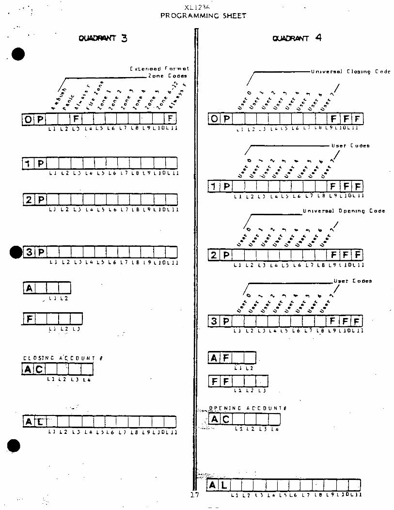
>;i123A PROGRAMMING SHEET
-3
[lIPI 1 I I ! 1 1 I I I 1 1 Ll L2 13 Le L5 16 L7 LB L9 LlOLll
[Z/PI I 1 1 I 1 ! 1 I LJ 12 L> LL LS Lb L7 18 L9LlO~ll
In] ^ 11 12
lEIIIn il 12 Ll
_-
CLOSING A‘CCOUNT d
]A!Cl I ‘1 I J Ll 12 L3 LO
/At-L-t“ 1 1 lllll!!!J 11 12 L> LA 1516 17 L8 L9LJOLl1
. . . :. . 1’
-4
U nlversel Closing C ode
Ll LZ LI L&L> L6 L7 LB LSLIOLII
U nlversel 0 penlng Lose
L-x- ’ -*bC\ 2 2 0’
a- a- 2 s 4 2 0’
a* 3 a4 a= a- a-
12lPl I I I ! ! I I lFlF!FJ Ll LZ L3 L(r LS Lb 17 LB LSLlOLll
Ll LZ ~3 L& is, Lb 17 LB L9LlOLl1
IAIFI I 1. Trz
fFFn-rj Ll L2 LJ
I I I I i-l Ll 12 I) Lo L5L6 L7 LB L9LlOLJl
. -1.
.a .
XL1236
. -’ PROGRAMMING SHEET
Co m man Pnone Prefix
i I I I! I ! I! I ] Ll LZ ~3 L6Ls Lb Li L8 L9Ll0Lll
1st Phone
fl!P! I I ! 1 1 I I I I I ] 11 L2 ~3 Lb LS Lb L7 LB L9 LlOLll
2nd Phone
f2ip( ! I ! I I ! ! 1 I ! [ Ll L2 L: Lrr L> Li L7 LB L9LlOLIl
3rd Phone
[SIPI I I I I 1 ! ! I 1 I 1 Ll L2 LJ Lb LS 16 L7 LB L9LlOLll
/ Receiver 1 I ype
Receiver 2 1 ype
l/l/
Aecelver 7 Type
Ll L2 LJ
Account NU mber
[AjC[ 1 1 1 ]
Ll L2 L3 Lb
Ll L2 LJ 16 LSL6 L7-L@. LSLl0Lll
COMMON 1ROlJBLE
R esponse
, [Oi~l I IFI I i I 1 IFI IF]
Ll L2 LJ LB L5 Lb L7 L8 k9LlOLLl
User 1 Startun Code
IA/Cl 1 1 1 ] cl LZ Ll Lb
4 . . :
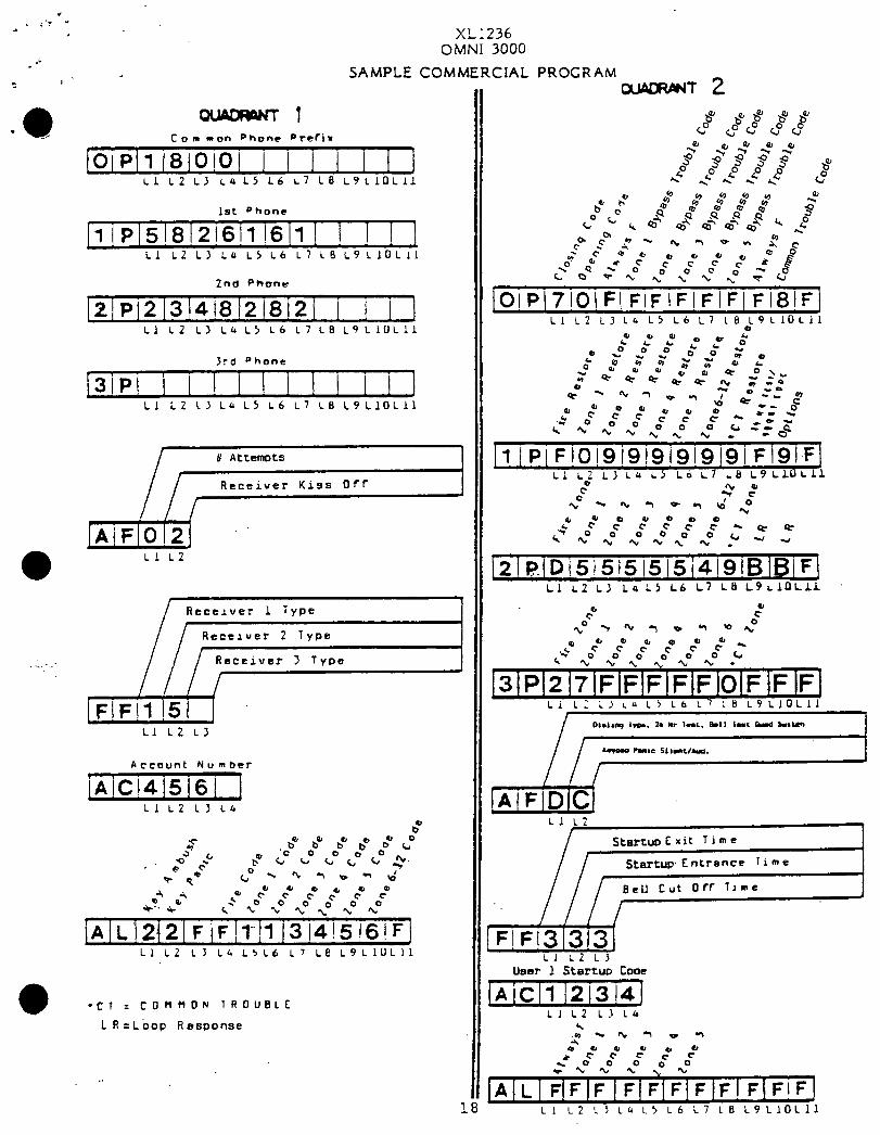
a XL1236 OMNI 3000
.j SAMPLECOMMERCIAL PROGRAM
Cam non Phone Prefix
lOlP/l J8]0!01 j 1 ] j 1 1 ] Ll L2 LJ LrcL5 16 L7 LB L9LlOLLl
1st phone
Ll L2 LY Lb LS Lb L7 18 L9LlOLll
2nd Phone
~2~P~2~3~418~2~8[2~ 1 i ] 1 Ll L2 L> LCr L5 L6 L7 LB ~9LlOLll
Jrd Phone
jslP! I 1 1 1 1 1 1 1 1 I ] Ll L2 LJ Lb L5 L6 L7 LB L9LlOLlI
/l] 1-j ..
a Ll L2
Receiver 1 Type
Receiver 2 Type /Ii . . . I : Receiver 3 Type
A ccaunt N u m her
~~1~14i516j ] Ll L2 Ll Lb
-CT = COt?nOu 1ROUBLE
L R=Lbop Response
8'
44 ,t 2 e" P e" co co 4 e c %O p *= *= \" *o c1 3 u . [2l~~D~5isl515!5i4!9lBlBiFl
Ll L2 L1 Lb L5 L6 L7 La L9LlOLLL
c” 2 2p -3 % 9 0 9 Y, *O
Ll c; 1
I SterruD C xit T i m e I
TTFEEtzj Ll LZ L3
User 1 Startuo Code
0 0 0 0 +” c c e c-! c
-0oono c
AILI;/;~~~~~F~~~F~~!F~F~F] Ll L2 L) Lll L5 L6 L7 LB L9LlOL11
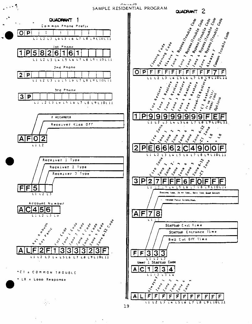
AL*&20
SAMPLE KESIDENTIAL PROGRAM
C 0 m mon Phone Pteflx
IOjPl ! I I I ! ! / ! I ! J Li L? ~3 ~lr L5 16 L) LB L9LIllcll
3rd Phone
[3!PI I ! ! I I. I i I I I ] Ll L2 LJ LU LS L6 L7 LB L9LIOLIl
li, II Attempts
Rece2ver Kiss Off ,
Li L2
Recerver 1 Tyoe
Receiver 2 Type
/ / / Receiver 3 Type
Account N u m her
[~lc141516l 1 Ll L2 LJ Li
Ll L2 LJ LO LSL6 L7 LB L9L10Lll
l * LR = Loop Response
Ll L2 LS L1) LSL6 L7 LBaL9~10L11
Li L2 L3 Lb L’j ~6 L7 L8 L9L10L11
Ll I:
Startuo Cxlt Time
Startuo Entrance Ti me
-Bell Cut OfT Time //I/ yFlm3]
Ll iz LJ User 1 Startup CO*