melsec-q/l/qna programming manual (pid control instructions) · mitsubishi shall have no...
TRANSCRIPT

MELSEC-Q/L/QnA Programming Manual(PID Control Instructions)

SAFETY PRECAUTIONS(Read these precautions before using this product.)
Before using this product, please read this manual and the relevant manuals carefully and pay full attention to safety to handle
the product correctly.
The precautions given in this manual are concerned with this product only. For the safety precautions of the programmable
controller system, refer to the user's manual for the CPU module used.
In this manual, the safety precautions are classified into two levels: " WARNING" and " CAUTION".
Under some circumstances, failure to observe the precautions given under " CAUTION" may lead to serious
consequences.
Observe the precautions of both levels because they are important for personal and system safety.
Make sure that the end users read this manual and then keep the manual in a safe place for future reference.
[Design Precautions]
WARNING● Configure safety circuits external to the programmable controller to ensure that the entire system
operates safely even when a fault occurs in the external power supply or the programmable controller.
Failure to do so may result in an accident due to an incorrect output or malfunction.
(1) Emergency stop circuits, protection circuits, and protective interlock circuits for conflicting
operations (such as forward/reverse rotations or upper/lower limit positioning) must be configured
external to the programmable controller.
(2) When the programmable controller detects an abnormal condition, it stops the operation and all
outputs are:
• Turned off if the overcurrent or overvoltage protection of the power supply module is activated.
• Held or turned off according to the parameter setting if the self-diagnostic function of the CPU
module detects an error such as a watchdog timer error.
(3) All outputs may be turned on if an error occurs in a part, such as an I/O control part, where the
CPU module cannot detect any error. To ensure safety operation in such a case, provide a safety
mechanism or a fail-safe circuit external to the programmable controller. For a fail-safe circuit
example, refer to "General Safety Requirements" in the MELSEC-L CPU Module User's Manual
(Hardware Design, Maintenance and Inspection).
● Configure a circuit so that the programmable controller is turned on first and then the external power
supply. If the external power supply is turned on first, an accident may occur due to an incorrect output
or malfunction.
WARNING Indicates that incorrect handling may cause hazardous conditions, resulting in death or severe injury.
CAUTION Indicates that incorrect handling may cause hazardous conditions, resulting in minor or moderate injury or property damage.
1

2
[Design Precautions]
[Startup and Maintenance Precautions]
WARNING● When connecting a peripheral with the CPU module or connecting an external device, such as a
personal computer, with an intelligent function module to modify data of a running programmable
controller, configure an interlock circuit in the program to ensure that the entire system will always
operate safely. For other forms of control (such as program modification or operating status change)
of a running programmable controller, read the relevant manuals carefully and ensure that the
operation is safe before proceeding. Especially, when a remote programmable controller is controlled
by an external device, immediate action cannot be taken if a problem occurs in the programmable
controller due to a communication failure. To prevent this, configure an interlock circuit in the program,
and determine corrective actions to be taken between the external device and CPU module in case of
a communication failure.
CAUTION● Before performing online operations (especially, program modification, forced output, and operating
status change) for the running CPU module from the peripheral connected, read relevant manuals
carefully and ensure the safety. Improper operation may damage machines or cause accidents.
CONDITIONS OF USE FOR THE PRODUCT(1) Mitsubishi programmable controller ("the PRODUCT") shall be used in conditions;
i) where any problem, fault or failure occurring in the PRODUCT, if any, shall not lead to any major or serious accident; and ii) where the backup and fail-safe function are systematically or automatically provided outside of the PRODUCT for the case of any problem, fault or failure occurring in the PRODUCT.
(2) The PRODUCT has been designed and manufactured for the purpose of being used in general industries.MITSUBISHI SHALL HAVE NO RESPONSIBILITY OR LIABILITY (INCLUDING, BUT NOT LIMITED TO ANY AND ALL RESPONSIBILITY OR LIABILITY BASED ON CONTRACT, WARRANTY, TORT, PRODUCT LIABILITY) FOR ANY INJURY OR DEATH TO PERSONS OR LOSS OR DAMAGE TO PROPERTY CAUSED BY the PRODUCT THAT ARE OPERATED OR USED IN APPLICATION NOT INTENDED OR EXCLUDED BY INSTRUCTIONS, PRECAUTIONS, OR WARNING CONTAINED IN MITSUBISHI'S USER, INSTRUCTION AND/OR SAFETY MANUALS, TECHNICAL BULLETINS AND GUIDELINES FOR the PRODUCT. ("Prohibited Application")Prohibited Applications include, but not limited to, the use of the PRODUCT in;• Nuclear Power Plants and any other power plants operated by Power companies, and/or any other cases in which the
public could be affected if any problem or fault occurs in the PRODUCT.• Railway companies or Public service purposes, and/or any other cases in which establishment of a special quality
assurance system is required by the Purchaser or End User.• Aircraft or Aerospace, Medical applications, Train equipment, transport equipment such as Elevator and Escalator,
Incineration and Fuel devices, Vehicles, Manned transportation, Equipment for Recreation and Amusement, and Safety devices, handling of Nuclear or Hazardous Materials or Chemicals, Mining and Drilling, and/or other applications where there is a significant risk of injury to the public or property.
Notwithstanding the above, restrictions Mitsubishi may in its sole discretion, authorize use of the PRODUCT in one or more of the Prohibited Applications, provided that the usage of the PRODUCT is limited only for the specific applications agreed to by Mitsubishi and provided further that no special quality assurance or fail-safe, redundant or other safety features which exceed the general specifications of the PRODUCTs are required. For details, please contact the Mitsubishi representative in your region.
3
4
CONTENTSSAFETY PRECAUTIONS . . . . . . . . . . . . . . . . . . . . . . . . . . . . . . . . . . . . . . . . . . . . . . . . . . . . . . . . . . . . . . . . . . . .1
CONDITIONS OF USE FOR THE PRODUCT . . . . . . . . . . . . . . . . . . . . . . . . . . . . . . . . . . . . . . . . . . . . . . . . . . . .3
MANUALS . . . . . . . . . . . . . . . . . . . . . . . . . . . . . . . . . . . . . . . . . . . . . . . . . . . . . . . . . . . . . . . . . . . . . . . . . . . . . . . .6
RELEVANT MANUALS . . . . . . . . . . . . . . . . . . . . . . . . . . . . . . . . . . . . . . . . . . . . . . . . . . . . . . . . . . . . . . . . . . . . . .6
GENERIC TERMS. . . . . . . . . . . . . . . . . . . . . . . . . . . . . . . . . . . . . . . . . . . . . . . . . . . . . . . . . . . . . . . . . . . . . . . . . .9
CHAPTER 1 GENERAL DESCRIPTION 10
1.1 PID Processing Method . . . . . . . . . . . . . . . . . . . . . . . . . . . . . . . . . . . . . . . . . . . . . . . . . . . . . . . . . . . . . . . . . . 11
CHAPTER 2 SYSTEM CONFIGURATION FOR PID CONTROL 12
2.1 Applicable CPU . . . . . . . . . . . . . . . . . . . . . . . . . . . . . . . . . . . . . . . . . . . . . . . . . . . . . . . . . . . . . . . . . . . . . . . . . 13
CHAPTER 3 PID CONTROL SPECIFICATIONS 14
3.1 PID Control by incomplete derivative . . . . . . . . . . . . . . . . . . . . . . . . . . . . . . . . . . . . . . . . . . . . . . . . . . . . . . . 14
Performance specifications . . . . . . . . . . . . . . . . . . . . . . . . . . . . . . . . . . . . . . . . . . . . . . . . . . . . . . . . . . . . . . . . . 14
PID operation block diagram and operation expressions . . . . . . . . . . . . . . . . . . . . . . . . . . . . . . . . . . . . . . . . . . 15
PID control instruction list . . . . . . . . . . . . . . . . . . . . . . . . . . . . . . . . . . . . . . . . . . . . . . . . . . . . . . . . . . . . . . . . . . 16
3.2 PID Control by Complete Derivative . . . . . . . . . . . . . . . . . . . . . . . . . . . . . . . . . . . . . . . . . . . . . . . . . . . . . . . . 20
Performance specifications . . . . . . . . . . . . . . . . . . . . . . . . . . . . . . . . . . . . . . . . . . . . . . . . . . . . . . . . . . . . . . . . . 20
PID operation block diagram and operation expressions . . . . . . . . . . . . . . . . . . . . . . . . . . . . . . . . . . . . . . . . . . 20
PID control instruction list . . . . . . . . . . . . . . . . . . . . . . . . . . . . . . . . . . . . . . . . . . . . . . . . . . . . . . . . . . . . . . . . . . 21
CHAPTER 4 FUNCTIONS OF PID CONTROL 25
4.1 Outline of PID Control . . . . . . . . . . . . . . . . . . . . . . . . . . . . . . . . . . . . . . . . . . . . . . . . . . . . . . . . . . . . . . . . . . . . 25
4.2 Functions of PID Control . . . . . . . . . . . . . . . . . . . . . . . . . . . . . . . . . . . . . . . . . . . . . . . . . . . . . . . . . . . . . . . . . 26
Operation method . . . . . . . . . . . . . . . . . . . . . . . . . . . . . . . . . . . . . . . . . . . . . . . . . . . . . . . . . . . . . . . . . . . . . . . . 26
Forward operation and reverse operation . . . . . . . . . . . . . . . . . . . . . . . . . . . . . . . . . . . . . . . . . . . . . . . . . . . . . . 26
Proportional operation (P operation) . . . . . . . . . . . . . . . . . . . . . . . . . . . . . . . . . . . . . . . . . . . . . . . . . . . . . . . . . . 27
Integral operation (I operation) . . . . . . . . . . . . . . . . . . . . . . . . . . . . . . . . . . . . . . . . . . . . . . . . . . . . . . . . . . . . . . 28
Derivative operation (D operation). . . . . . . . . . . . . . . . . . . . . . . . . . . . . . . . . . . . . . . . . . . . . . . . . . . . . . . . . . . . 29
PID operation. . . . . . . . . . . . . . . . . . . . . . . . . . . . . . . . . . . . . . . . . . . . . . . . . . . . . . . . . . . . . . . . . . . . . . . . . . . . 30
4.3 Other Functions. . . . . . . . . . . . . . . . . . . . . . . . . . . . . . . . . . . . . . . . . . . . . . . . . . . . . . . . . . . . . . . . . . . . . . . . . 31
Bumpless changeover function . . . . . . . . . . . . . . . . . . . . . . . . . . . . . . . . . . . . . . . . . . . . . . . . . . . . . . . . . . . . . . 31
MV upper/lower limit control function. . . . . . . . . . . . . . . . . . . . . . . . . . . . . . . . . . . . . . . . . . . . . . . . . . . . . . . . . . 31
Function for transfer to the SV storage device for the PV in manual mode. . . . . . . . . . . . . . . . . . . . . . . . . . . . . 32
Changing the PID control data or input/output data setting range (for QCPU and LCPU) . . . . . . . . . . . . . . . . . 33
CHAPTER 5 PID CONTROL PROCEDURE 34
5.1 PID Control Data . . . . . . . . . . . . . . . . . . . . . . . . . . . . . . . . . . . . . . . . . . . . . . . . . . . . . . . . . . . . . . . . . . . . . . . . 36
Number of loops to be used and the number of loops to be executed in a single scan . . . . . . . . . . . . . . . . . . . 49
Sampling cycle . . . . . . . . . . . . . . . . . . . . . . . . . . . . . . . . . . . . . . . . . . . . . . . . . . . . . . . . . . . . . . . . . . . . . . . . . . 50
5.2 I/O Data. . . . . . . . . . . . . . . . . . . . . . . . . . . . . . . . . . . . . . . . . . . . . . . . . . . . . . . . . . . . . . . . . . . . . . . . . . . . . . . . 51
CHAPTER 6 PID CONTROL INSTRUCTIONS 56
CHAPTER 7 HOW TO READ EXPLANATIONS FOR INSTRUCTIONS 58

CO
NT
EN
TS
CHAPTER 8 INCOMPLETE DERIVATIVE PID CONTROL INSTRUCTIONS AND PROGRAM EXAMPLES 60
8.1 PID Control Instructions . . . . . . . . . . . . . . . . . . . . . . . . . . . . . . . . . . . . . . . . . . . . . . . . . . . . . . . . . . . . . . . . . . 60
PID control data settings . . . . . . . . . . . . . . . . . . . . . . . . . . . . . . . . . . . . . . . . . . . . . . . . . . . . . . . . . . . . . . . . . . . 60
PID operation. . . . . . . . . . . . . . . . . . . . . . . . . . . . . . . . . . . . . . . . . . . . . . . . . . . . . . . . . . . . . . . . . . . . . . . . . . . . 61
Operation stop/start of designated loop no.. . . . . . . . . . . . . . . . . . . . . . . . . . . . . . . . . . . . . . . . . . . . . . . . . . . . . 63
Parameter change at designated loop. . . . . . . . . . . . . . . . . . . . . . . . . . . . . . . . . . . . . . . . . . . . . . . . . . . . . . . . . 64
8.2 PID Control Program Examples . . . . . . . . . . . . . . . . . . . . . . . . . . . . . . . . . . . . . . . . . . . . . . . . . . . . . . . . . . . . 66
System configuration for program examples . . . . . . . . . . . . . . . . . . . . . . . . . . . . . . . . . . . . . . . . . . . . . . . . . . . . 66
Program example for automatic mode PID control . . . . . . . . . . . . . . . . . . . . . . . . . . . . . . . . . . . . . . . . . . . . . . . 66
Program example for changing the PID control mode between automatic and manual . . . . . . . . . . . . . . . . . . . 69
CHAPTER 9 COMPLETE DERIVATIVE PID CONTROL INSTRUCTIONS AND PROGRAM EXAMPLES 72
9.1 PID Control Instructions . . . . . . . . . . . . . . . . . . . . . . . . . . . . . . . . . . . . . . . . . . . . . . . . . . . . . . . . . . . . . . . . . . 72
PID control data settings . . . . . . . . . . . . . . . . . . . . . . . . . . . . . . . . . . . . . . . . . . . . . . . . . . . . . . . . . . . . . . . . . . . 72
PID control. . . . . . . . . . . . . . . . . . . . . . . . . . . . . . . . . . . . . . . . . . . . . . . . . . . . . . . . . . . . . . . . . . . . . . . . . . . . . . 74
Monitoring PID control status (QnACPU only). . . . . . . . . . . . . . . . . . . . . . . . . . . . . . . . . . . . . . . . . . . . . . . . . . . 76
Operation stop/start of designated loop no.. . . . . . . . . . . . . . . . . . . . . . . . . . . . . . . . . . . . . . . . . . . . . . . . . . . . . 78
Parameter change at designated loop. . . . . . . . . . . . . . . . . . . . . . . . . . . . . . . . . . . . . . . . . . . . . . . . . . . . . . . . . 79
9.2 PID Control Program Examples (for QCPU and LCPU) . . . . . . . . . . . . . . . . . . . . . . . . . . . . . . . . . . . . . . . . . 81
System configuration for program examples . . . . . . . . . . . . . . . . . . . . . . . . . . . . . . . . . . . . . . . . . . . . . . . . . . . . 81
Program example for automatic mode PID control . . . . . . . . . . . . . . . . . . . . . . . . . . . . . . . . . . . . . . . . . . . . . . . 81
Program example for changing the PID control mode between automatic and manual . . . . . . . . . . . . . . . . . . . 84
9.3 PID Control Program Examples (QnACPU only) . . . . . . . . . . . . . . . . . . . . . . . . . . . . . . . . . . . . . . . . . . . . . . 87
System configuration for program examples . . . . . . . . . . . . . . . . . . . . . . . . . . . . . . . . . . . . . . . . . . . . . . . . . . . . 87
Program example for automatic mode PID control . . . . . . . . . . . . . . . . . . . . . . . . . . . . . . . . . . . . . . . . . . . . . . . 88
Program example for changing the PID control mode between automatic and manual . . . . . . . . . . . . . . . . . . . 92
APPENDICES 96
Appendix 1 Processing Time List. . . . . . . . . . . . . . . . . . . . . . . . . . . . . . . . . . . . . . . . . . . . . . . . . . . . . . . . . . . . . . . . 96
Appendix 2 Anti-Reset Windup Measure . . . . . . . . . . . . . . . . . . . . . . . . . . . . . . . . . . . . . . . . . . . . . . . . . . . . . . . . . 100
INDEX 101
INSTRUCTION INDEX 103
REVISIONS. . . . . . . . . . . . . . . . . . . . . . . . . . . . . . . . . . . . . . . . . . . . . . . . . . . . . . . . . . . . . . . . . . . . . . . . . . . . .105
WARRANTY . . . . . . . . . . . . . . . . . . . . . . . . . . . . . . . . . . . . . . . . . . . . . . . . . . . . . . . . . . . . . . . . . . . . . . . . . . . .106
5
6
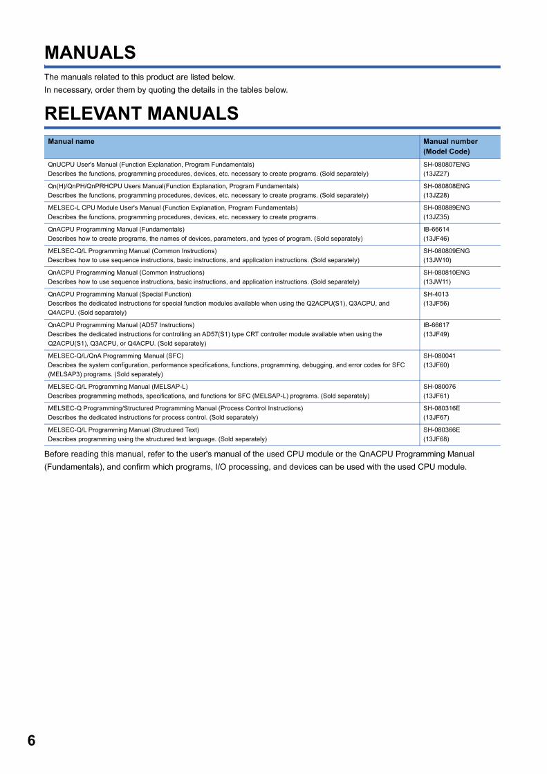
MANUALSThe manuals related to this product are listed below.
In necessary, order them by quoting the details in the tables below.
RELEVANT MANUALS
Before reading this manual, refer to the user's manual of the used CPU module or the QnACPU Programming Manual
(Fundamentals), and confirm which programs, I/O processing, and devices can be used with the used CPU module.
Manual name Manual number(Model Code)
QnUCPU User's Manual (Function Explanation, Program Fundamentals)
Describes the functions, programming procedures, devices, etc. necessary to create programs. (Sold separately)
SH-080807ENG
(13JZ27)
Qn(H)/QnPH/QnPRHCPU Users Manual(Function Explanation, Program Fundamentals)
Describes the functions, programming procedures, devices, etc. necessary to create programs. (Sold separately)
SH-080808ENG
(13JZ28)
MELSEC-L CPU Module User's Manual (Function Explanation, Program Fundamentals)
Describes the functions, programming procedures, devices, etc. necessary to create programs.
SH-080889ENG
(13JZ35)
QnACPU Programming Manual (Fundamentals)
Describes how to create programs, the names of devices, parameters, and types of program. (Sold separately)
IB-66614
(13JF46)
MELSEC-Q/L Programming Manual (Common Instructions)
Describes how to use sequence instructions, basic instructions, and application instructions. (Sold separately)
SH-080809ENG
(13JW10)
QnACPU Programming Manual (Common Instructions)
Describes how to use sequence instructions, basic instructions, and application instructions. (Sold separately)
SH-080810ENG
(13JW11)
QnACPU Programming Manual (Special Function)
Describes the dedicated instructions for special function modules available when using the Q2ACPU(S1), Q3ACPU, and
Q4ACPU. (Sold separately)
SH-4013
(13JF56)
QnACPU Programming Manual (AD57 Instructions)
Describes the dedicated instructions for controlling an AD57(S1) type CRT controller module available when using the
Q2ACPU(S1), Q3ACPU, or Q4ACPU. (Sold separately)
IB-66617
(13JF49)
MELSEC-Q/L/QnA Programming Manual (SFC)
Describes the system configuration, performance specifications, functions, programming, debugging, and error codes for SFC
(MELSAP3) programs. (Sold separately)
SH-080041
(13JF60)
MELSEC-Q/L Programming Manual (MELSAP-L)
Describes programming methods, specifications, and functions for SFC (MELSAP-L) programs. (Sold separately)
SH-080076
(13JF61)
MELSEC-Q Programming/Structured Programming Manual (Process Control Instructions)
Describes the dedicated instructions for process control. (Sold separately)
SH-080316E
(13JF67)
MELSEC-Q/L Programming Manual (Structured Text)
Describes programming using the structured text language. (Sold separately)
SH-080366E
(13JF68)

When QCPU is used
When LCPU is used
7

8
When QnACPU is used
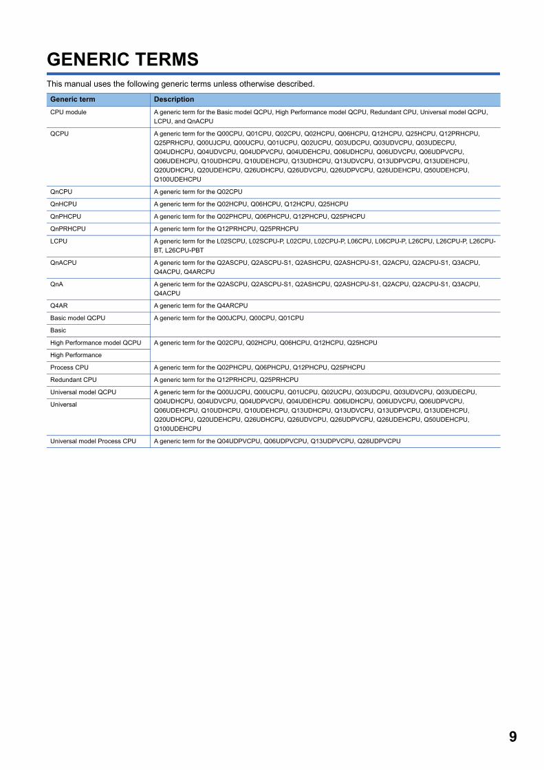
GENERIC TERMSThis manual uses the following generic terms unless otherwise described.
Generic term Description
CPU module A generic term for the Basic model QCPU, High Performance model QCPU, Redundant CPU, Universal model QCPU,
LCPU, and QnACPU
QCPU A generic term for the Q00CPU, Q01CPU, Q02CPU, Q02HCPU, Q06HCPU, Q12HCPU, Q25HCPU, Q12PRHCPU,
Q25PRHCPU, Q00UJCPU, Q00UCPU, Q01UCPU, Q02UCPU, Q03UDCPU, Q03UDVCPU, Q03UDECPU,
Q04UDHCPU, Q04UDVCPU, Q04UDPVCPU, Q04UDEHCPU, Q06UDHCPU, Q06UDVCPU, Q06UDPVCPU,
Q06UDEHCPU, Q10UDHCPU, Q10UDEHCPU, Q13UDHCPU, Q13UDVCPU, Q13UDPVCPU, Q13UDEHCPU,
Q20UDHCPU, Q20UDEHCPU, Q26UDHCPU, Q26UDVCPU, Q26UDPVCPU, Q26UDEHCPU, Q50UDEHCPU,
Q100UDEHCPU
QnCPU A generic term for the Q02CPU
QnHCPU A generic term for the Q02HCPU, Q06HCPU, Q12HCPU, Q25HCPU
QnPHCPU A generic term for the Q02PHCPU, Q06PHCPU, Q12PHCPU, Q25PHCPU
QnPRHCPU A generic term for the Q12PRHCPU, Q25PRHCPU
LCPU A generic term for the L02SCPU, L02SCPU-P, L02CPU, L02CPU-P, L06CPU, L06CPU-P, L26CPU, L26CPU-P, L26CPU-
BT, L26CPU-PBT
QnACPU A generic term for the Q2ASCPU, Q2ASCPU-S1, Q2ASHCPU, Q2ASHCPU-S1, Q2ACPU, Q2ACPU-S1, Q3ACPU,
Q4ACPU, Q4ARCPU
QnA A generic term for the Q2ASCPU, Q2ASCPU-S1, Q2ASHCPU, Q2ASHCPU-S1, Q2ACPU, Q2ACPU-S1, Q3ACPU,
Q4ACPU
Q4AR A generic term for the Q4ARCPU
Basic model QCPU A generic term for the Q00JCPU, Q00CPU, Q01CPU
Basic
High Performance model QCPU A generic term for the Q02CPU, Q02HCPU, Q06HCPU, Q12HCPU, Q25HCPU
High Performance
Process CPU A generic term for the Q02PHCPU, Q06PHCPU, Q12PHCPU, Q25PHCPU
Redundant CPU A generic term for the Q12PRHCPU, Q25PRHCPU
Universal model QCPU A generic term for the Q00UJCPU, Q00UCPU, Q01UCPU, Q02UCPU, Q03UDCPU, Q03UDVCPU, Q03UDECPU,
Q04UDHCPU, Q04UDVCPU, Q04UDPVCPU, Q04UDEHCPU. Q06UDHCPU, Q06UDVCPU, Q06UDPVCPU,
Q06UDEHCPU, Q10UDHCPU, Q10UDEHCPU, Q13UDHCPU, Q13UDVCPU, Q13UDPVCPU, Q13UDEHCPU,
Q20UDHCPU, Q20UDEHCPU, Q26UDHCPU, Q26UDVCPU, Q26UDPVCPU, Q26UDEHCPU, Q50UDEHCPU,
Q100UDEHCPU
Universal
Universal model Process CPU A generic term for the Q04UDPVCPU, Q06UDPVCPU, Q13UDPVCPU, Q26UDPVCPU
9
10
1 GENERAL DESCRIPTION
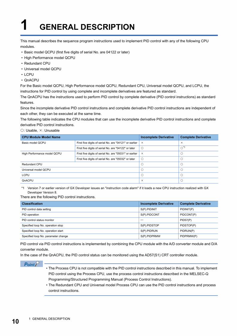
This manual describes the sequence program instructions used to implement PID control with any of the following CPU
modules.
• Basic model QCPU (first five digits of serial No. are 04122 or later)
• High Performance model QCPU
• Redundant CPU
• Universal model QCPU
• LCPU
• QnACPU
For the Basic model QCPU, High Performance model QCPU, Redundant CPU, Universal model QCPU, and LCPU, the
instructions for PID control by using complete and incomplete derivatives are featured as standard.
The QnACPU has the instructions used to perform PID control by complete derivative (PID control instructions) as standard
features.
Since the incomplete derivative PID control instructions and complete derivative PID control instructions are independent of
each other, they can be executed at the same time.
The following table indicates the CPU modules that can use the incomplete derivative PID control instructions and complete
derivative PID control instructions.
: Usable, : Unusable
*1 Version 7 or earlier version of GX Developer issues an "instruction code alarm" if it loads a new CPU instruction realized with GX Developer Version 8.
There are the following PID control instructions.
PID control via PID control instructions is implemented by combining the CPU module with the A/D converter module and D/A
converter module.
In the case of the QnACPU, the PID control status can be monitored using the AD57(S1) CRT controller module.
• The Process CPU is not compatible with the PID control instructions described in this manual. To implement
PID control using the Process CPU, use the process control instructions described in the MELSEC-Q
Programming/Structured Programming Manual (Process Control Instructions).
• The Redundant CPU and Universal model Process CPU can use the PID control instructions and process
control instructions.
CPU Module Model Name Incomplete Derivative Complete Derivative
Basic model QCPU First five digits of serial No. are "04121" or earlier
First five digits of serial No. are "04122" or later *1
High Performance model QCPU First five digits of serial No. are "05031" or earlier
First five digits of serial No. are "05032" or later
Redundant CPU
Universal model QCPU
LCPU
QnACPU
Classification Incomplete Derivative Complete Derivative
PID control data setting S(P).PIDINIT PIDINIT(P)
PID operation S(P).PIDCONT PIDCONT(P)
PID control status monitor PID57(P)
Specified loop No. operation stop S(P).PIDSTOP PIDSTOP(P)
Specified loop No. operation start S(P).PIDRUN PIDRUN(P)
Specified loop No. parameter change S(P).PIDPRMW PIDPRMW(P)
1 GENERAL DESCRIPTION
1
1.1 PID Processing MethodThis section describes the processing method for PID control using PID control instructions. ( Page 25 FUNCTIONS OFPID CONTROL)
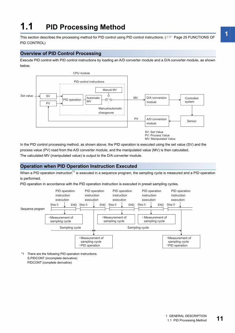
Overview of PID Control ProcessingExecute PID control with PID control instructions by loading an A/D converter module and a D/A converter module, as shown
below.
In the PID control processing method, as shown above, the PID operation is executed using the set value (SV) and the
process value (PV) read from the A/D converter module, and the manipulated value (MV) is then calculated.
The calculated MV (manipulated value) is output to the D/A converter module.
Operation when PID Operation Instruction ExecutedWhen a PID operation instruction*1 is executed in a sequence program, the sampling cycle is measured and a PID operation
is performed.
PID operation in accordance with the PID operation instruction is executed in preset sampling cycles.
*1 There are the following PID operation instructions.S.PIDCONT (incomplete derivative)PIDCONT (complete derivative)
1 GENERAL DESCRIPTION1.1 PID Processing Method 11

12
2 SYSTEM CONFIGURATION FOR PID CONTROL
This chapter describes the system configuration for PID control using the PID control instructions.
Settings of SV, PV, and MV used in the PID control instructionsSet a value within the following range.
• With PID limits (0 to 2000)
• Without PID limits (-32768 to 32767)
*1 When the resolution of the A/D converter module or D/A converter module used for I/O of PID control is other than 0 to 2000, convert the digital values into 0 to 2000.
CPU Module Type SV, PV, MV
With PID limits*1 Without PID limits
Basic model QCPU
High Performance model QCPU
Redundant CPU
Universal model QCPU
LCPU
QnACPU
2 SYSTEM CONFIGURATION FOR PID CONTROL
2
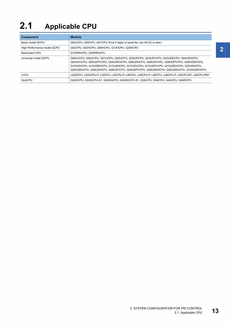
2.1 Applicable CPUComponent Module
Basic model QCPU Q00JCPU, Q00CPU, Q01CPU (First 5 digits of serial No. are 04122 or later)
High Performance model QCPU Q02CPU, Q02HCPU, Q06HCPU, Q12HCPU, Q25HCPU
Redundant CPU Q12PRHCPU, Q25PRHCPU
Universal model QCPU Q00UJCPU, Q00UCPU, Q01UCPU, Q02UCPU, Q03UDCPU, Q03UDVCPU, Q03UDECPU, Q04UDHCPU,
Q04UDVCPU, Q04UDPVCPU, Q04UDEHCPU, Q06UDHCPU, Q06UDVCPU, Q06UDPVCPU, Q06UDEHCPU,
Q10UDHCPU, Q10UDEHCPU, Q13UDHCPU, Q13UDVCPU, Q13UDPVCPU, Q13UDEHCPU, Q20UDHCPU,
Q20UDEHCPU, Q26UDHCPU, Q26UDVCPU, Q26UDPVCPU, Q26UDEHCPU, Q50UDEHCPU, Q100UDEHCPU
LCPU L02SCPU, L02SCPU-P, L02CPU, L02CPU-P, L06CPU, L06CPU-P, L26CPU, L26CPU-P, L26CPU-BT, L26CPU-PBT
QnACPU Q2ASCPU, Q2ASCPU-S1, Q2ASHCPU, Q2ASHCPU-S1, Q2ACPU, Q3ACPU, Q4ACPU, Q4ARCPU
2 SYSTEM CONFIGURATION FOR PID CONTROL2.1 Applicable CPU 13

14
3 PID CONTROL SPECIFICATIONS
This section gives the specifications PID operation using PID control instructions.
3.1 PID Control by incomplete derivative
Performance specificationsThe performance specifications for PID control are tabled below.
: Unusable
Item Specifications
With PID limits Without PID limits QnACPU
Basic model QCPU
High Performance model QCPU, Redundant CPU, Universal model QCPU, LCPU
Basic model QCPU
High Performance model QCPU, Redundant CPU, Universal model QCPU, LCPU
Number of PID control loops 8 loops (maximum) 32 loops (maximum) 8 loops (maximum) 32 loops (maximum)
Sampling cycle TS 0.01 to 60.00s
PID operation method Process value differentiation incomplete derivative (forward operation/reverse operation)
PID
constant
setting
range
Proportional
constant
KP 0.01 to 100.00
Integral
constant
TI 0.1 to 3000.0s
Derivative
constant
TD 0.00 to 300.00s
Derivative gain KD 0.00 to 300.00
SV (set value) setting range SV 0 to 2000 -32768 to 32767
PV (process value) setting
range
PV -50 to 2050 -32768 to 32767
MV (manipulated value) output
range
MV
3 PID CONTROL SPECIFICATIONS3.1 PID Control by incomplete derivative

3
PID operation block diagram and operation expressions
PID operation block diagramThe PID operation block diagram for incomplete derivative is shown below.
Operation expressionsThe operation expressions for PID control using PID control instructions are indicated below.
*1 PVfn is calculated using the following expression.Therefore, it is the same as the PV (process value) of the input data as long as the filter coefficient is not set for the input data.Process Value after Filtering PVfn = PVn + (PVfn-1 - PVn)PVn: Process value of the present sampling cycle: Filter coefficientPVfn-1: Process value of the preceding sampling cycle (after filtering)PVfn is stored in the I/O data area. ( Page 51 I/O Data)
Name Operation Expressions Meanings of Symbols
Process value
differentiation
Incomplete
derivative
Forward
operation
EVn: Deviation in the present sampling cycle
EVn-1: Deviation in the preceding sampling cycle
SV: Set value
PVfn: Process value of the present sampling cycle (after
filtering)
PVfn-1: Process value of the preceding sampling cycle
(after filtering)
PVfn-2: Process value of the sampling cycle two cycles
before (after filtering)
MV: Output change value
MVn: Present manipulation value
Dn: Present derivative term
Dn-1: Derivative term of the preceding sampling cycle
KP: Proportional constant
TS: Sampling cycle
TI: Integral constant
TD: Derivative constant
KD: Derivative gain
Reverse
operation
3 PID CONTROL SPECIFICATIONS3.1 PID Control by incomplete derivative 15

16
PID control instruction listA list of the instructions used to execute PID control is given below.
: Usable, : Unusable
*1 For the Basic model QCPU, High Performance model QCPU, Redundant CPU, Universal model QCPU, and LCPU, "with or without PID limits" can be selected.Refer to Sections 5.1 and 5.2 for details of the setting range when "with/without PID limits" has been selected. Page 36 PID Control Data, Page 51 I/O Data
Instruction Name Processing Details CPU
QCPU, LCPU QnACPU
S.PIDINIT Sets the reference data for PID operation. *1
S.PIDCONT Executes PID operation with the SV (set value) and the PV (process value). *1
S.PIDSTOP
S.PIDRUN
Stops or starts PID operation for the set loop No.
S.PIDPRMW Changes the operation parameters for the designated loop number to PID
control data.
*1
3 PID CONTROL SPECIFICATIONS3.1 PID Control by incomplete derivative
3
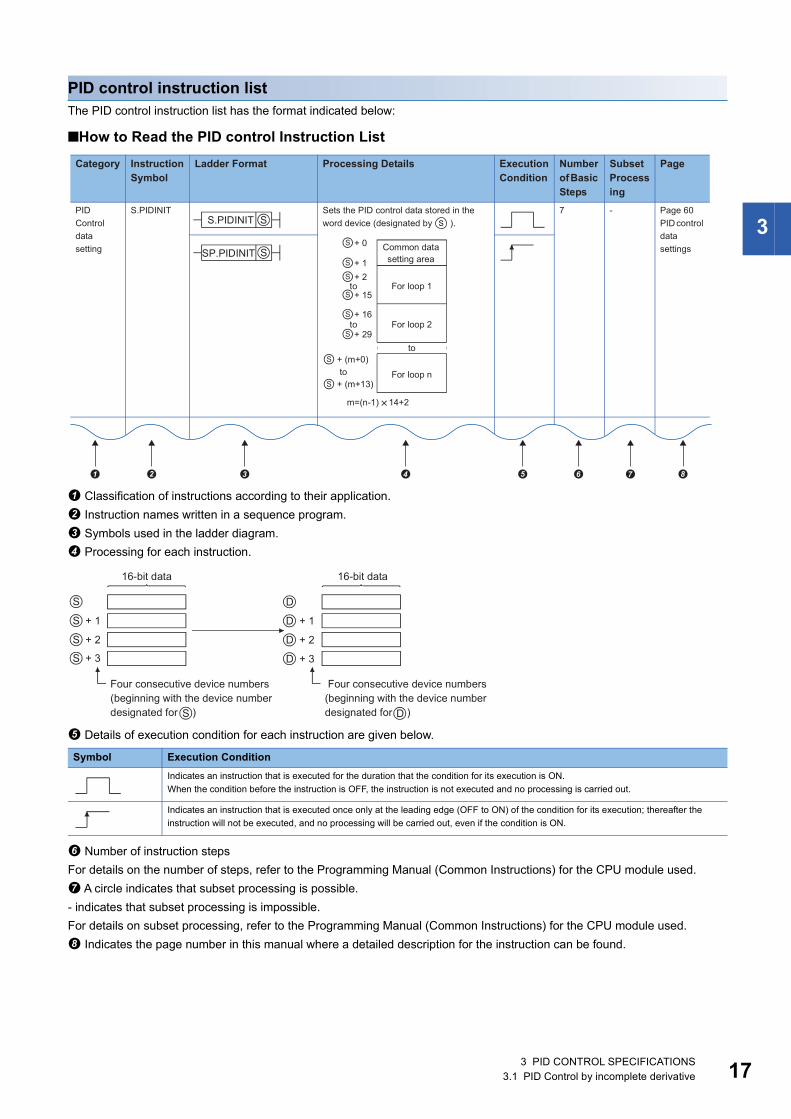
PID control instruction listThe PID control instruction list has the format indicated below:
■How to Read the PID control Instruction List
Classification of instructions according to their application.
Instruction names written in a sequence program.
Symbols used in the ladder diagram.
Processing for each instruction.
Details of execution condition for each instruction are given below.
Number of instruction steps
For details on the number of steps, refer to the Programming Manual (Common Instructions) for the CPU module used.
A circle indicates that subset processing is possible.
- indicates that subset processing is impossible.
For details on subset processing, refer to the Programming Manual (Common Instructions) for the CPU module used.
Indicates the page number in this manual where a detailed description for the instruction can be found.
Symbol Execution Condition
Indicates an instruction that is executed for the duration that the condition for its execution is ON.
When the condition before the instruction is OFF, the instruction is not executed and no processing is carried out.
Indicates an instruction that is executed once only at the leading edge (OFF to ON) of the condition for its execution; thereafter the
instruction will not be executed, and no processing will be carried out, even if the condition is ON.
� � � � � � �
3 PID CONTROL SPECIFICATIONS3.1 PID Control by incomplete derivative 17

18
■PID Control Instruction List
Category Instruction Symbol
Ladder Format Processing Details Execution Condition
Number of Basic Steps
Subset Processing
Page
PID
Control
data
setting
S.PIDINIT Sets the PID control data stored in the
word device (designated by ).
7 - Page 60
PID control
data
settings
PID
operation
S.PIDCONT Executes PID operation with the SV (set
value) and the PV (process value)
designated by and stores the PID
operation results in the MV (manipulated
value) area of the word device designated
by .
7 - Page 61
PID
operation
Operation
stop
S.PIDSTOP Stops the PID operation at the loop
number designated by .
7 - Page 63
Operation
stop/start
of
designated
loop no.
Operation
start
S.PIDRUN Starts the operation at the loop number
designated by .
6 - Page 63
Operation
stop/start
of
designated
loop no.
Parameter
change
S.PIDPRMW Changes the operation parameter for the
loop number designated by to the PID
control data stored in the word device
designated by
8 - Page 64
Parameter
change at
designated
loop
S
S
S
n
n
n
S
3 PID CONTROL SPECIFICATIONS3.1 PID Control by incomplete derivative
3
• "PID operation by incomplete derivative" and "PID operation by complete derivative" can be executed
simultaneously since they are independent.
• When the S(P).PIDINIT instruction has been used to make initialization, use the S(P).PIDCONT instruction
to perform PID operation. To stop and start the PID operation of the specified loop No. and to change the
PID control data, use the S(P).PIDSTOP, S(P).PIDRUN and S(P).PIDPRMW instructions accordingly.
3 PID CONTROL SPECIFICATIONS3.1 PID Control by incomplete derivative 19
20
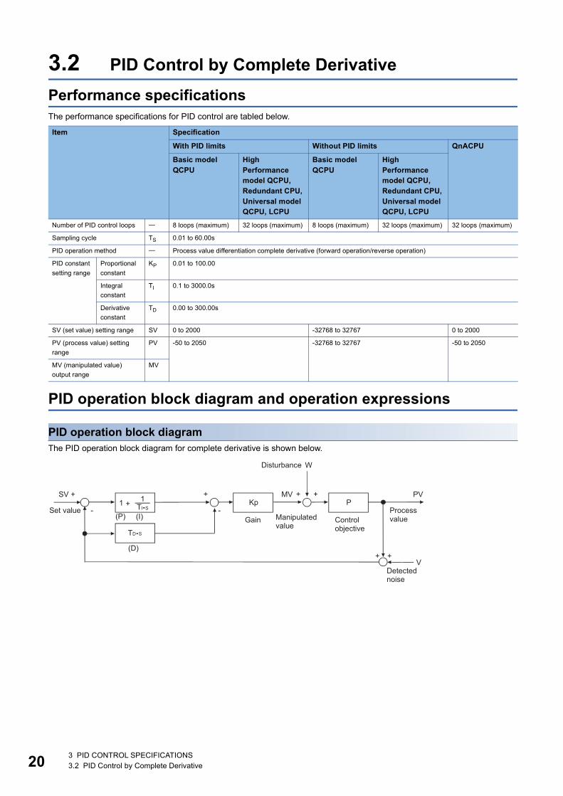
3.2 PID Control by Complete Derivative
Performance specificationsThe performance specifications for PID control are tabled below.
PID operation block diagram and operation expressions
PID operation block diagramThe PID operation block diagram for complete derivative is shown below.
Item Specification
With PID limits Without PID limits QnACPU
Basic model QCPU
High Performance model QCPU, Redundant CPU, Universal model QCPU, LCPU
Basic model QCPU
High Performance model QCPU, Redundant CPU, Universal model QCPU, LCPU
Number of PID control loops 8 loops (maximum) 32 loops (maximum) 8 loops (maximum) 32 loops (maximum) 32 loops (maximum)
Sampling cycle TS 0.01 to 60.00s
PID operation method Process value differentiation complete derivative (forward operation/reverse operation)
PID constant
setting range
Proportional
constant
KP 0.01 to 100.00
Integral
constant
TI 0.1 to 3000.0s
Derivative
constant
TD 0.00 to 300.00s
SV (set value) setting range SV 0 to 2000 -32768 to 32767 0 to 2000
PV (process value) setting
range
PV -50 to 2050 -32768 to 32767 -50 to 2050
MV (manipulated value)
output range
MV
3 PID CONTROL SPECIFICATIONS3.2 PID Control by Complete Derivative
3
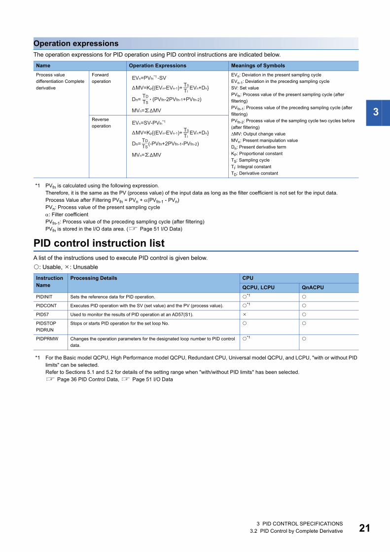
Operation expressionsThe operation expressions for PID operation using PID control instructions are indicated below.
*1 PVfn is calculated using the following expression.Therefore, it is the same as the PV (process value) of the input data as long as the filter coefficient is not set for the input data.Process Value after Filtering PVfn = PVn + (PVfn-1 - PVn)PVn: Process value of the present sampling cycle: Filter coefficientPVfn-1: Process value of the preceding sampling cycle (after filtering)PVfn is stored in the I/O data area. ( Page 51 I/O Data)
PID control instruction listA list of the instructions used to execute PID control is given below.
: Usable, : Unusable
*1 For the Basic model QCPU, High Performance model QCPU, Redundant CPU, Universal model QCPU, and LCPU, "with or without PID limits" can be selected.Refer to Sections 5.1 and 5.2 for details of the setting range when "with/without PID limits" has been selected. Page 36 PID Control Data, Page 51 I/O Data
Name Operation Expressions Meanings of Symbols
Process value
differentiation Complete
derivative
Forward
operation
EVn: Deviation in the present sampling cycle
EVn-1: Deviation in the preceding sampling cycle
SV: Set value
PVfn: Process value of the present sampling cycle (after
filtering)
PVfn-1: Process value of the preceding sampling cycle (after
filtering)
PVfn-2: Process value of the sampling cycle two cycles before
(after filtering)
MV: Output change value
MVn: Present manipulation value
Dn: Present derivative term
KP: Proportional constant
TS: Sampling cycle
TI: Integral constant
TD: Derivative constant
Reverse
operation
Instruction Name
Processing Details CPU
QCPU, LCPU QnACPU
PIDINIT Sets the reference data for PID operation. *1
PIDCONT Executes PID operation with the SV (set value) and the PV (process value). *1
PID57 Used to monitor the results of PID operation at an AD57(S1).
PIDSTOP
PIDRUN
Stops or starts PID operation for the set loop No.
PIDPRMW Changes the operation parameters for the designated loop number to PID control
data.
*1
3 PID CONTROL SPECIFICATIONS3.2 PID Control by Complete Derivative 21

22
The PID control instruction listThe PID control instruction list has the format indicated below:
■How to Read the PID control Instruction List
Classification of instructions according to their application.
Instruction names written in a sequence program.
Symbols used in the ladder diagram.
Processing for each instruction.
Details of execution condition for each instruction are given below.
Number of instruction steps
For details on the number of steps, refer to the QCPU (Q mode) /QnACPU Programming Manual (Common Instructions).
A circle indicates that subset processing is possible.
- indicates that subset processing is impossible.
For details on subset processing, refer to the QCPU (Q mode) /QnACPU Programming Manual (Common Instructions).
Indicates the page number in this manual where a detailed description for the instruction can be found.
Symbol Execution Condition
Indicates an instruction that is executed for the duration that the condition for its execution is ON. When the condition before the
instruction is OFF, the instruction is not executed and no processing is carried out.
Indicates an instruction that is executed once only at the leading edge (OFF to ON) of the condition for its execution; thereafter the
instruction will not be executed, and no processing will be carried out, even if the condition is ON.
� � � � � � �
3 PID CONTROL SPECIFICATIONS3.2 PID Control by Complete Derivative

3
■PID Control Instruction List
Category Instruction Symbol
Ladder Format Processing Details Execution Condition
Number of Basic Steps
Subset Processing
Page
PID control
data setting
PIDINIT Sets the PID control data stored in the
word device (designated by ).
2 - Page 72
PID control
data
settings
PID
operation
PIDCONT Executes PID operation with the SV (set
value) and the PV (process value)
designated by and stores the PID
operation results in the MV (manipulated
value) area of the word device
designated by .
2 - Page 74
PID control
Monitoring PID57 Monitors the PID operation results for the
AD57 (S1) (designated by ).
: First I/O number of the AD57(S1)
: Monitor screen number
1: Loop 1 to loop 8
2: Loop 9 to loop16
3: Loop17 to loop24
4: Loop25 to loop32
: Initial screen display request
4 - Page 76
Monitoring
PID control
status
(QnACPU
only)
Operation
stop
PIDSTOP Stops the PID operation at the loop
number designated by .
2 - Page 78
Operation
stop/start
of
designated
loop no.
Operation
start
PIDRUN Starts the operation at the loop number
designated by .
2 - Page 78
Operation
stop/start
of
designated
loop no.
S
S
S
n
n
S1
S2
n
n
3 PID CONTROL SPECIFICATIONS3.2 PID Control by Complete Derivative 23

24
• "PID operation by incomplete derivative" and "PID operation by complete derivative" can be executed
simultaneously since they are independent.
• When the PIDINIT(P) instruction was used to make initialization, use the PIDCONT(P) instruction to perform
PID operation. To stop and start the PID operation of the specified loop No. and to change the PID control
data, use the PIDSTOP(P) instruction, PIDRUN(P) instruction and PIDPRMW(P) instruction.
Parameter
change
PIDPRMW Changes the operation parameter for the
loop number designated by to the
PID control data stored in the word
device designated by
3 - Page 79
Parameter
change at
designated
loop
Category Instruction Symbol
Ladder Format Processing Details Execution Condition
Number of Basic Steps
Subset Processing
Page
n
S
3 PID CONTROL SPECIFICATIONS3.2 PID Control by Complete Derivative

4
4 FUNCTIONS OF PID CONTROL
This chapter describes PID control performed using the PID control instructions.
4.1 Outline of PID ControlPID control is applicable to process control in which factors such as flowrate, velocity, air flow volume, temperature, tension,
mixing ratio, etc. must be controlled.
During PID control, the value measured by the sensor (process value) is compared with the preset value (set value). The
output value (manipulated value) is then adjusted in order to eliminate the difference between the process value and the set
value.
The MV (manipulated value) is calculated by combining the proportional operation (P), the integral operation (I), and the
derivative operation (D) so that the PV is brought to the same value as the SV quickly and precisely.
The MV is made large when the difference between the PV and the SV is large so as to bring the PV close to the SV quickly.
As the difference between the PV and the SV gets smaller, a smaller MV is used to bring the PV to the same value as the SV
gradually and accurately.
4 FUNCTIONS OF PID CONTROL4.1 Outline of PID Control 25
26
4.2 Functions of PID Control
Operation methodThe operation methods for PID control with the PID control instructions are the velocity type and process value derivative
type. The following describes the control executed for both of these methods:
Velocity type operationThe velocity type operation calculates amounts of changes in the MVs (manipulated values) during PID operation.
The actual MV is the accumulated amount of change of the MV calculated for each sampling cycle.
Process value derivative type operationThe process value derivative type operation executes PID operations by differentiating the PV (process value).
Because the deviation is not subject to differentiation, sudden changes in the output due to differentiation of the changes in
the deviation generated by changing the set value can be reduced.
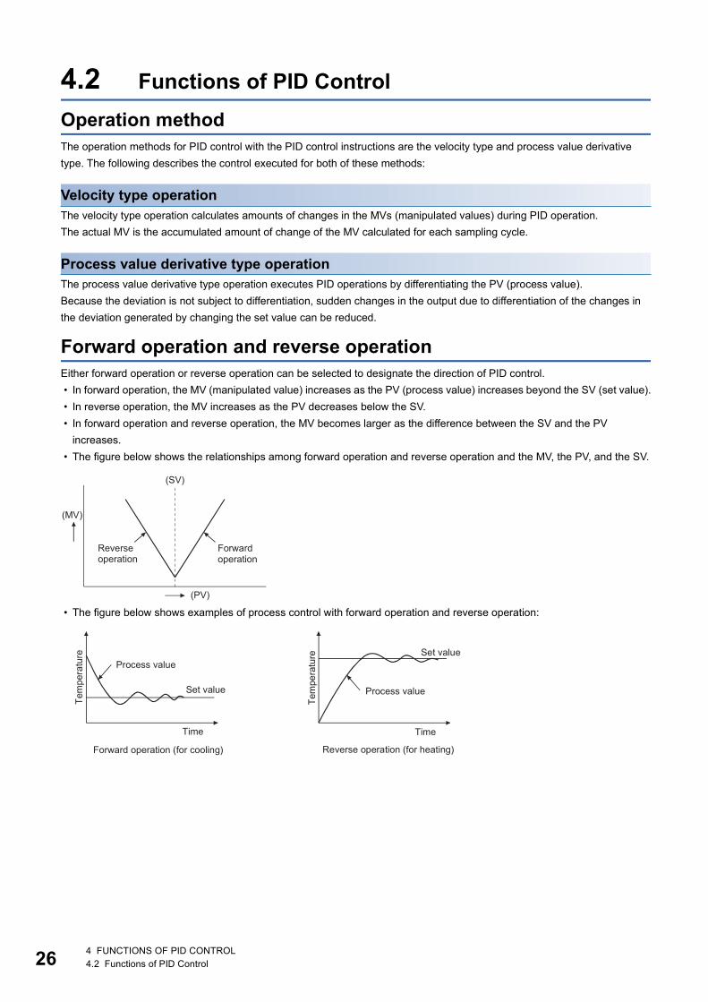
Forward operation and reverse operationEither forward operation or reverse operation can be selected to designate the direction of PID control.
• In forward operation, the MV (manipulated value) increases as the PV (process value) increases beyond the SV (set value).
• In reverse operation, the MV increases as the PV decreases below the SV.
• In forward operation and reverse operation, the MV becomes larger as the difference between the SV and the PV
increases.
• The figure below shows the relationships among forward operation and reverse operation and the MV, the PV, and the SV.
• The figure below shows examples of process control with forward operation and reverse operation:
4 FUNCTIONS OF PID CONTROL4.2 Functions of PID Control
4
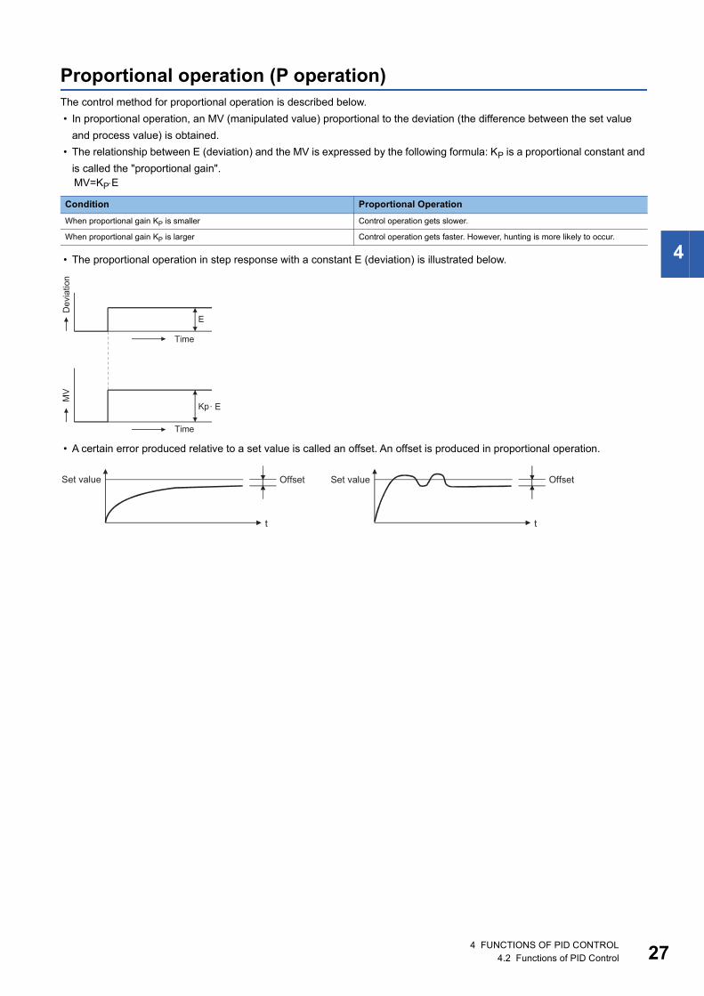
Proportional operation (P operation)The control method for proportional operation is described below.
• In proportional operation, an MV (manipulated value) proportional to the deviation (the difference between the set value
and process value) is obtained.
• The relationship between E (deviation) and the MV is expressed by the following formula: KP is a proportional constant and
is called the "proportional gain".
• The proportional operation in step response with a constant E (deviation) is illustrated below.
• A certain error produced relative to a set value is called an offset. An offset is produced in proportional operation.
MV=KPE
Condition Proportional Operation
When proportional gain KP is smaller Control operation gets slower.
When proportional gain KP is larger Control operation gets faster. However, hunting is more likely to occur.
4 FUNCTIONS OF PID CONTROL4.2 Functions of PID Control 27
28
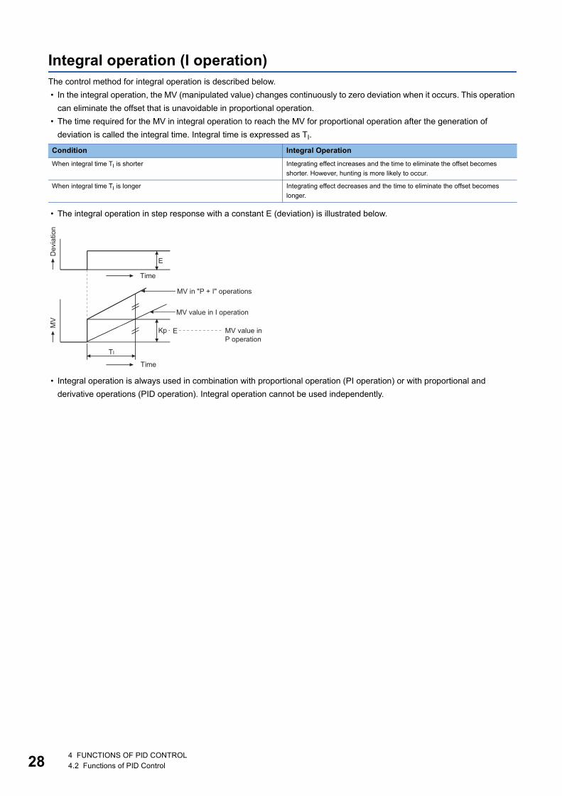
Integral operation (I operation)The control method for integral operation is described below.
• In the integral operation, the MV (manipulated value) changes continuously to zero deviation when it occurs. This operation
can eliminate the offset that is unavoidable in proportional operation.
• The time required for the MV in integral operation to reach the MV for proportional operation after the generation of
deviation is called the integral time. Integral time is expressed as TI.
• The integral operation in step response with a constant E (deviation) is illustrated below.
• Integral operation is always used in combination with proportional operation (PI operation) or with proportional and
derivative operations (PID operation). Integral operation cannot be used independently.
Condition Integral Operation
When integral time TI is shorter Integrating effect increases and the time to eliminate the offset becomes
shorter. However, hunting is more likely to occur.
When integral time TI is longer Integrating effect decreases and the time to eliminate the offset becomes
longer.
4 FUNCTIONS OF PID CONTROL4.2 Functions of PID Control
4
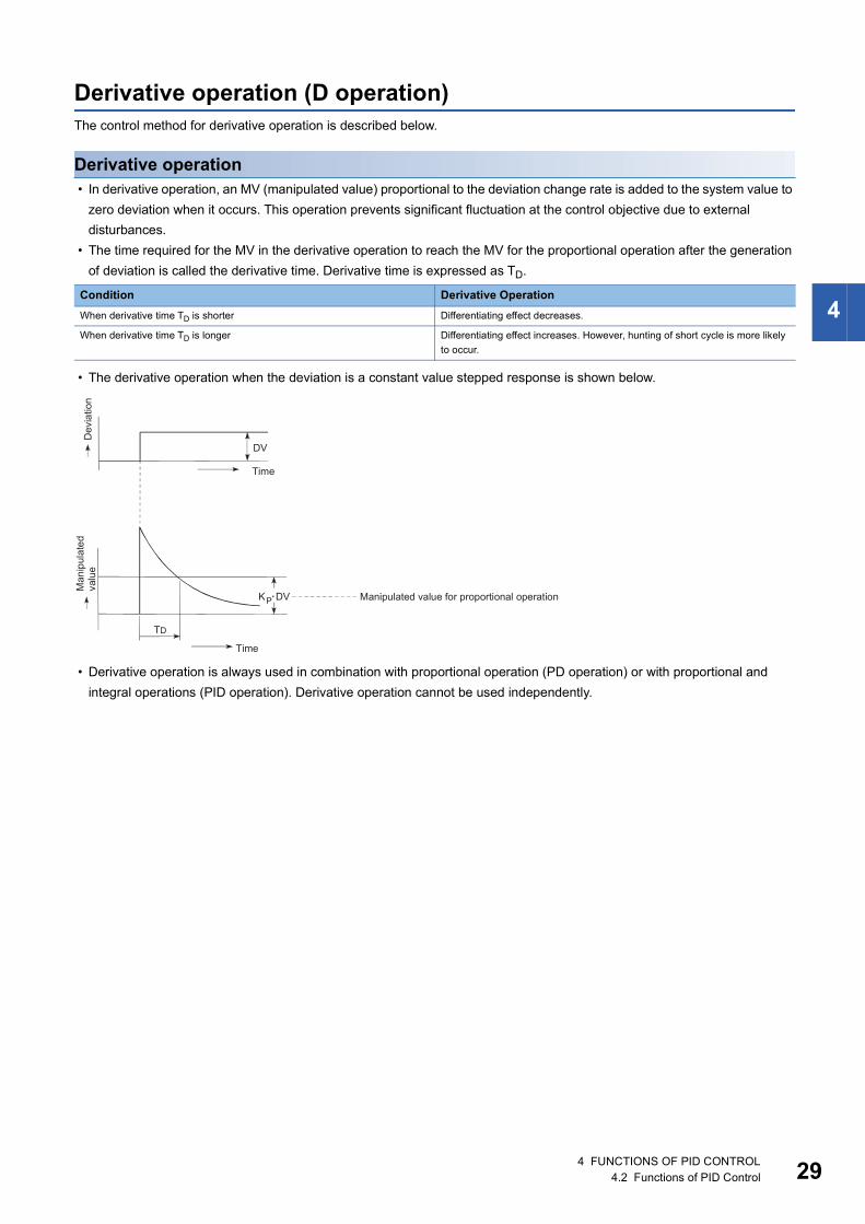
Derivative operation (D operation)The control method for derivative operation is described below.
Derivative operation • In derivative operation, an MV (manipulated value) proportional to the deviation change rate is added to the system value to
zero deviation when it occurs. This operation prevents significant fluctuation at the control objective due to external
disturbances.
• The time required for the MV in the derivative operation to reach the MV for the proportional operation after the generation
of deviation is called the derivative time. Derivative time is expressed as TD.
• The derivative operation when the deviation is a constant value stepped response is shown below.
• Derivative operation is always used in combination with proportional operation (PD operation) or with proportional and
integral operations (PID operation). Derivative operation cannot be used independently.
Condition Derivative Operation
When derivative time TD is shorter Differentiating effect decreases.
When derivative time TD is longer Differentiating effect increases. However, hunting of short cycle is more likely
to occur.
4 FUNCTIONS OF PID CONTROL4.2 Functions of PID Control 29

30
About the differences between complete derivative and incomplete derivative
■[Incomplete derivative]Incomplete derivative is PID control that has a primary delay filter in the input of a derivative term.
The S.PIDCONT instruction is the incomplete derivative PID control instruction.
Incomplete derivative is effective for the following cases.
• Control susceptible to high-frequency noise
• When energy effective to actuate an operation end is not given when a step change occurs in a complete derivative system
■[Complete derivative]Complete derivative is PID control that uses the input of a derivative term as it is.
The PIDCONT instruction is the complete derivative PID control instruction.
PID operationThe control method when proportional operation (P operation), integral operation (I operation), and derivative operation (D
operation) are used in combination is described below.
• During PID operation, the system is controlled by the MV (manipulated value) calculated in the (P + I + D) operation.
• PID operation in step response with a constant E (deviation) is illustrated below.
4 FUNCTIONS OF PID CONTROL4.2 Functions of PID Control

4
4.3 Other FunctionsDuring PID control using the PID control instructions, MV upper/lower limit control is automatically executed by the bumpless
changeover function explained below.
Bumpless changeover function • This function controls the MV (manipulated value) continuously when the control mode is changed between manual and
automatic.
• When the mode is changed (between manual and automatic), data is transferred between the "MV area for automatic mode
(automatic MV)" and "MV area for manual mode (manual MV)" as described below. The control mode is changed in the I/O
data area ( Page 51 I/O Data).
Manual and automatic modes of PID control:
• Automatic mode: PID operation is executed with a PID control instruction. The control object is controlled
according to the calculated MV.
• Manual mode: PID operation is not executed. The MV is calculated by the user and the control object is
controlled according to the user-calculated MV.
The loop set in the manual mode stores the PV (process value) in the set value area every sampling cycle.
MV upper/lower limit control function • The MV upper/lower limit control function controls the upper or lower limit of the MV calculated in the PID operation. This
function is only effective in the automatic mode. It cannot be executed in the manual mode.
• By setting the MV upper limit (MVHL) and the MV lower limit (MVLL), the MV calculated in the PID operation can be
controlled within the range between the limits.
• When the MV upper/lower limit control is used, the MV is controlled as illustrated above. A MVHL (MV upper limit) and
MVLL (MV lower limit) takes on a value between -50 and 2050 or a user-defined value (except the QnACPU). The following
are the default settings: The value set for the upper limit must not be smaller than the value set for the lower limit. An error
will occur if it is.
Mode switching Description
Changing from the manual mode to the automatic mode The MV in the manual mode is transmitted to the MV area for the automatic mode.
Changing from the automatic mode to the manual mode The MV in the automatic mode is transmitted to the MV area for the manual mode.
MV Default value
Upper limit 2000 (Or user-defined value)
Lower limit 0 (Or user-defined value)
4 FUNCTIONS OF PID CONTROL4.3 Other Functions 31

32
Function for transfer to the SV storage device for the PV in manual modeWhen using the PID control instruction to perform PID control, execute the PID operation instruction also in the manual mode.
In the manual mode, it is possible to select whether the PV imported from the A/D converter module is transferred to the SV
storage device or not when the PID operation instruction is executed, depending on the ON/OFF status of the PID bumpless
processing flag (SM774, SM794).
Mode switching from manual to automatic depending on ON/OFF of SM774 and SM794There are the following differences in control when the manual mode is switched to the automatic mode.
• When SM774/SM794 is OFF, the PV is transferred to the SV storage device. Therefore, there is no difference between the
PV and SV when the manual mode is switched to the automatic mode. Hence, an abrupt change does not occur in MV at
the time of mode switching. Instead, since the SV after mode switching differs from the target value in the automatic mode,
the user should change the SV to the target value step by step in the sequence program.
• When SM774/SM794 is ON, the PV is not transferred to the SV storage device. Therefore, there is a difference between
the PV and SV when the manual mode is switched to the automatic mode. If the difference is large at the time of mode
switching, an abrupt change may occur in MV. Use this method in a system where the mode is switched when the PV has
fully neared the SV. PID control in the automatic mode can be executed immediately without the SV being changed step by
step in the sequence program.
The SV and PV are stored into the devices specified in the I/O data area with the PID operation instruction.
PID Bumpless Processing Flag Operation
SM794 (Incomplete derivative)
SM774 (Complete derivative)
OFF • The PV is transferred to the SV storage device when the PID operation instruction is executed.
• When the manual mode is switched to the automatic mode, the MV output in the manual mode is
continued.
• When the SV is changed after switching to the automatic mode, control is performed to achieve the SV,
starting from the MV output in the manual mode.
ON • The PV is not transferred to the SV storage device when the PID operation instruction is executed.
• When the manual mode is switched to the automatic mode, control is performed to achieve the SV,
starting from the MV output in the manual mode.
• Before switching to the automatic mode, store the SV into the SV storage device.
4 FUNCTIONS OF PID CONTROL4.3 Other Functions
4
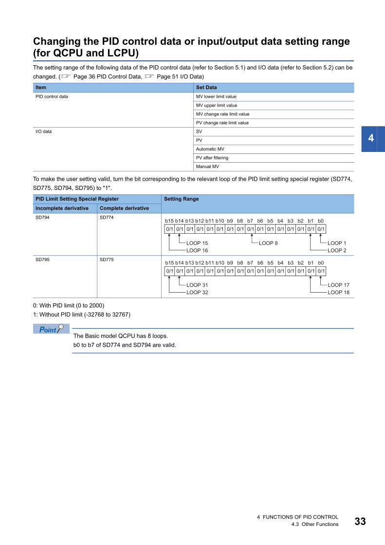
Changing the PID control data or input/output data setting range (for QCPU and LCPU)The setting range of the following data of the PID control data (refer to Section 5.1) and I/O data (refer to Section 5.2) can be
changed. ( Page 36 PID Control Data, Page 51 I/O Data)
To make the user setting valid, turn the bit corresponding to the relevant loop of the PID limit setting special register (SD774,
SD775, SD794, SD795) to "1".
0: With PID limit (0 to 2000)
1: Without PID limit (-32768 to 32767)
The Basic model QCPU has 8 loops.
b0 to b7 of SD774 and SD794 are valid.
Item Set Data
PID control data MV lower limit value
MV upper limit value
MV change rate limit value
PV change rate limit value
I/O data SV
PV
Automatic MV
PV after filtering
Manual MV
PID Limit Setting Special Register Setting Range
Incomplete derivative Complete derivative
SD794 SD774
SD795 SD775
4 FUNCTIONS OF PID CONTROL4.3 Other Functions 33

34
5 PID CONTROL PROCEDURE
The programming procedure required to execute PID control is shown below.
(1)
(2)
(3)
(3)
(3)
� �
*1
5 PID CONTROL PROCEDURE

5
(1) Page 36 PID Control Data
(2) Page 60 PID control data settings, Page 72 PID control data settings
(3) Page 51 I/O Data
(4) Page 61 PID operation, Page 74 PID control
(5) The MV, obtained from the PID operation result, is stored in the I/O data area. ( Page 51 I/O Data)
(6) This step is not necessary when monitoring is not required.
• Registering or changing the PID control data per sequence program scan will present no problem. However,
execute the the PID control data setting instructions *2 when you registered or changed the PID control
data. If you do not execute the PID control data setting instructions instruction, the data registered or the
correction made to the PID control data will not be reflected at the execution of the the PID operation
instructions.
• You need not execute the PID control data setting instructions when using the parameter change instruction *3 to change the PID control data per loop.
*1 The following instructions are available as the PID operation instructions.S.PIDCONT (incomplete derivative)PIDCONT (complete derivative)
*2 The following instructions are available as the PID control data setting instructions.S.PIDINIT (incomplete derivative)PIDINIT (complete derivative)
*3 The following instructions are available as the parameter change instructions.S. PIDPRMW (incomplete derivative)PIDPRMW (complete derivative)
� �
(4)
(5)
(6)
5 PID CONTROL PROCEDURE 35

36
5.1 PID Control DataPID control data is used to set the reference values for PID operation.
Store the PID control data into the CPU module with the PID control data setting*2 instruction before executing PID operation
instruction*1.
The PID control data is classified into two types, "common data for all loops" and "data for individual loops".
*1 The following are available as the PID operation instructions.S.PIDCONT (incomplete derivative)PIDCONT (complete derivative)
*2 The following are available as the PID control data setting instructions.S.PIDINIT (incomplete derivative)PIDINIT (complete derivative)
PID Control Data List
■For Basic model QCPU • Incomplete derivative
Setting data
Data No.
Data Item Description Incomplete derivative Processing when Set Data is Outside the Allowable Setting Range
With PID limits Without PID limits
Setting Range
User Specification Range
Setting Range
User Specification Range
Common
setting
data
1 Number of
loops
Sets the number of loops
for which PID operation
will be executed.
1 to 8 1 to 8 1 to 8 1 to 8 An error occurs
and PID operation
is not executed for
all loops.2 Number of
loops in one
scan
Sets the number of loops
for which single PID
operation will be
executed when the
multiple loops reaches
the sampling cycle time.
1 to 8 1 to 8 1 to 8 1 to 8
5 PID CONTROL PROCEDURE5.1 PID Control Data

5
Data for
each loop
1 Selection of
operational
expression
Selects the PID
operational expression
indicated in Section
3.1.2/Section 3.2.2. (
Page 15 Operation
expressions, Page
21 Operation
expressions)
Forward
operation: 0
Reverse
operation: 1
0 or 1 Forward
operation: 0
Reverse
operation: 1
0 or 1 An error occurs
and PID operation
for the
corresponding
loop is not
executed.
2 Sampling
cycle (TS)
Sets the cycle of PID
operation.
0.01 to
60.00s
1 to 6000
(unit: 10 ms)
0.01 to 60.00s 1 to 6000
(unit: 10 ms)
3 Proportional
constant (KP)
PID operation
Proportional gain
0.01 to
100.00
1 to 10000
(unit: 0.01)
0.01 to 100.00 1 to 10000
(unit: 0.01)
4 Integral
constant (TI)
This constant expresses
the magnitude of the
integral operation (I
operation) effect.
Increasing the integral
constant slows down the
manipulated value
change.
0.1 to
3000.0s
1 to 32767
(unit: 100 ms)
0.1 to 3000.0s 1 to 32767
(unit: 100 ms)
An error occurs
and PID operation
for the
corresponding
loop is not
executed.
Infinite()
(If the setting
for TI
exceeds
3000.0 s)
Infinite()
(If the setting
for TI exceeds
3000.0 s)
5 Derivative
constant (TD)
This constant expresses
the magnitude of the
derivative operation (D
operation) effect.
Increasing the derivative
constant causes a
significant change in the
manipulated value even
with slight change of the
control objective.
0.00 to
300.00s
0 to 30000
(unit: 10 ms)
0.00 to
300.00s
0 to 30000
(unit: 10 ms)
An error occurs
and PID operation
for the
corresponding
loop is not
executed.
6 Filter
coefficient ()
Sets the degree of
filtering applied to the
process value.
The filtering effect
decreases as the value
gets closer to 0.
0 to 100% 0 to 100 0 to 100% 0 to 100
7 MV Lower
limit (MVLL)
In the automatic mode,
sets the lower limit for the
MV (manipulated value)
calculated in PID
operation.
When the MV is less than
the MV lower limit, the
MVLL is used as the MV.
-50 to 2050 -50 to 2050 -32768 to
32767
-32768 to
32767
In the case of
"with PID limits",
PID operation is
performed after
conversion into
the following
value.
• When the MVLL
or MVHL value
is less than -50,
"-50" is used.
• When the MVLL
or MVHL value
is greater than
2050, "2050" is
used.
8 MV Upper
limit (MVHL)
In the automatic mode,
sets the upper limit for
the MV calculated in PID
operation.
When the MV is greater
than the MV upper limit,
the MVHL is used as the
MV.
-50 to 2050 -50 to 2050 -32768 to
32767
-32768 to
32767
Setting data
Data No.
Data Item Description Incomplete derivative Processing when Set Data is Outside the Allowable Setting Range
With PID limits Without PID limits
Setting Range
User Specification Range
Setting Range
User Specification Range
5 PID CONTROL PROCEDURE5.1 PID Control Data 37
38
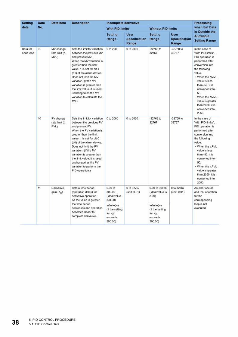
Data for
each loop
9 MV change
rate limit (
MVL)
Sets the limit for variation
between the previous MV
and present MV.
When the MV variation is
greater than the limit
value, 1 is set for bit 1
(b1) of the alarm device.
Does not limit the MV
variation. (If the MV
variation is greater than
the limit value, it is used
unchanged as the MV
variation to calculate the
MV.)
0 to 2000 0 to 2000 -32768 to
32767
-32768 to
32767
In the case of
"with PID limits",
PID operation is
performed after
conversion into
the following
value.
• When the MVL
value is less
than -50, it is
converted into -
50.
• When the MVL
value is greater
than 2050, it is
converted into
2050.
10 PV change
rate limit (
PVL)
Sets the limit for variation
between the previous PV
and present PV.
When the PV variation is
greater than the limit
value, 1 is set for bit 0
(b0) of the alarm device.
Does not limit the PV
variation. (If the PV
variation is greater than
the limit value, it is used
unchanged as the PV
variation to perform the
PID operation.)
0 to 2000 0 to 2000 -32768 to
32767
-32768 to
32767
In the case of
"with PID limits",
PID operation is
performed after
conversion into
the following
value.
• When the PVL
value is less
than -50, it is
converted into -
50.
• When the PVL
value is greater
than 2050, it is
converted into
2050.
11 Derivative
gain (KD)
Sets a time period
(operation delay) for
derivative operation.
As the value is greater,
the time period
decreases and operation
becomes closer to
complete derivative.
0.00 to
300.00
(Ideal value
is 8.00)
0 to 32767
(unit: 0.01)
0.00 to 300.00
(Ideal value is
8.00)
0 to 32767
(unit: 0.01)
An error occurs
and PID operation
for the
corresponding
loop is not
executed.Infinite()
(If the setting
for KD
exceeds
300.00)
Infinite()
(If the setting
for KD
exceeds
300.00)
Setting data
Data No.
Data Item Description Incomplete derivative Processing when Set Data is Outside the Allowable Setting Range
With PID limits Without PID limits
Setting Range
User Specification Range
Setting Range
User Specification Range
5 PID CONTROL PROCEDURE5.1 PID Control Data

5
• Complete derivative
Setting data
Data No.
Data Item Description Complete derivative Processing when Set Data is Outside the Allowable Setting Range
With PID limits Without PID limits
Setting Range
User Specification Range
Setting Range
User Specification Range
Common
setting
data
1 Number of
loops
Sets the number of loops
for which PID operation
will be executed.
1 to 8 1 to 8 1 to 8 1 to 8 An error occurs
and PID operation
is not executed for
all loops.2 Number of
loops in one
scan
Sets the number of loops
for which single PID
operation will be
executed when the
multiple loops reaches
the sampling cycle time.
1 to 8 1 to 8 1 to 8 1 to 8
Data for
each loop
1 Selection of
operational
expression
Selects the PID
operational expression
indicated in Section
3.1.2/Section 3.2.2. (
Page 15 Operation
expressions, Page
21 Operation
expressions)
Forward
operation: 0
Reverse
operation: 1
0 or 1 Forward
operation: 0
Reverse
operation: 1
0 or 1 An error occurs
and PID operation
for the
corresponding
loop is not
executed.
2 Sampling
cycle (TS)
Sets the cycle of PID
operation.
0.01 to
60.00s
1 to 6000
(unit: 10 ms)
0.01 to 60.00s 1 to 6000
(unit: 10 ms)
3 Proportional
constant (KP)
PID operation
proportional gain
0.01 to
100.00
1 to 10000
(unit: 0.01)
0.01 to 100.00 1 to 10000
(unit: 0.01)
4 Integral
constant (TI)
This constant expresses
the magnitude of the
integral operation (I
operation) effect.
Increasing the integral
constant slows down the
manipulated value
change.
0.1 to
3000.0s
1 to 32767
(unit: 100 ms)
0.1 to 3000.0s 1 to 32767
(unit: 100 ms)
An error occurs
and PID operation
for the
corresponding
loop is not
executed.
Infinite()
(If the setting
for TI
exceeds
3000.0 s)
Infinite()
(If the setting
for TI exceeds
3000.0 s)
5 Derivative
constant (TD)
This constant expresses
the magnitude of the
derivative operation (D
operation) effect.
Increasing the derivative
constant causes a
significant change in the
manipulated value even
with slight change of the
control objective.
0.00 to
300.00s
0 to 30000
(unit: 10 ms)
0.00 to
300.00s
0 to 30000
(unit: 10 ms)
An error occurs
and PID operation
for the
corresponding
loop is not
executed.
6 Filter
coefficient ()
Sets the degree of
filtering applied to the
process value.
The filtering effect
decreases as the value
gets closer to 0.
0 to 100% 0 to 100 0 to 100% 0 to 100
7 MV Lower
limit (MVLL)
In the automatic mode,
sets the lower limit for the
MV (manipulated value)
calculated in PID
operation.
When the MV is less than
the MV lower limit, the
MVLL is used as the MV.
-50 to 2050 -50 to 2050 -32768 to
32767
-32768 to
32767
In the case of
"with PID limits",
PID operation is
performed after
conversion into
the following
value.
• When the MVLL
or MVHL value
is less than -50,
"-50" is used.
• When the MVLL
or MVHL value
is greater than
2050, "2050" is
used.
8 MV Upper
limit (MVHL)
In the automatic mode,
sets the upper limit for
the MV calculated in PID
operation.
When the MV is greater
than the MV upper limit,
the MVHL is used as the
MV.
-50 to 2050 -50 to 2050 -32768 to
32767
-32768 to
32767
5 PID CONTROL PROCEDURE5.1 PID Control Data 39
40
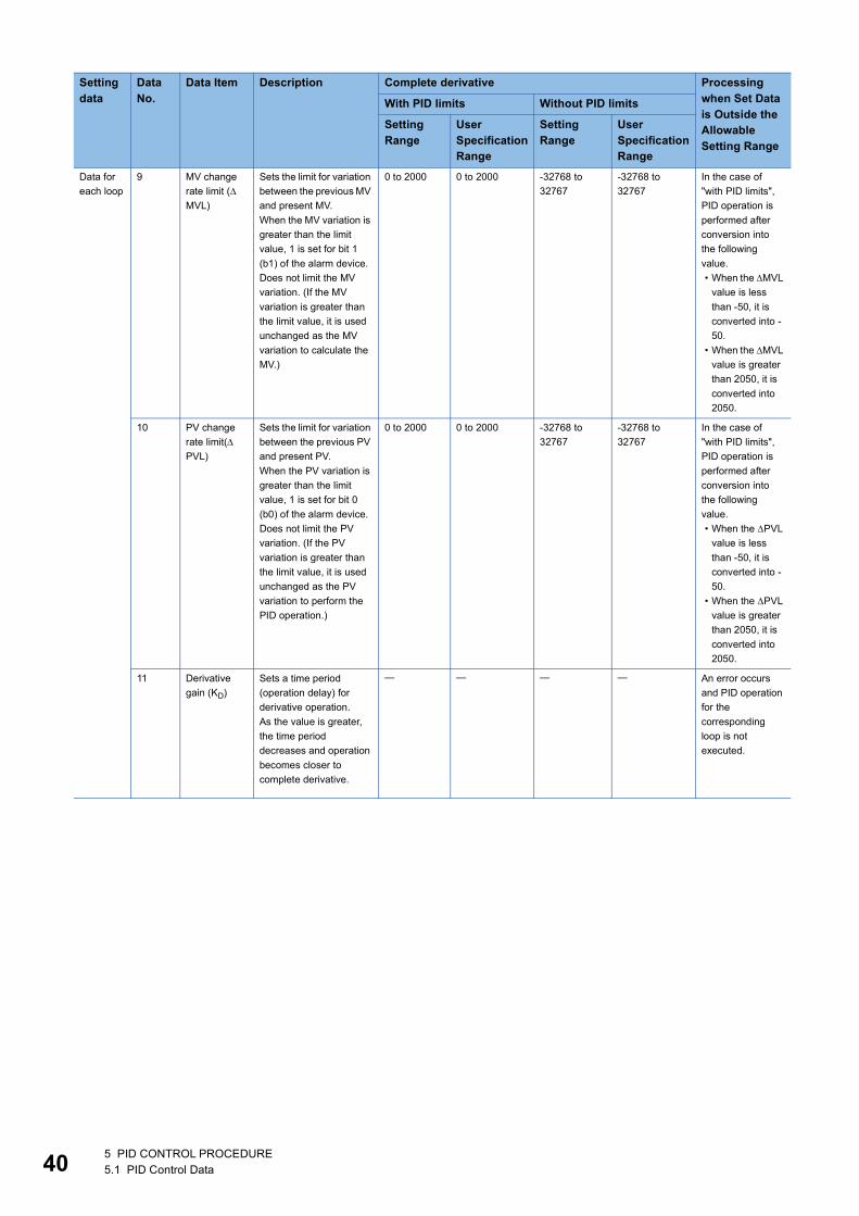
Data for
each loop
9 MV change
rate limit (
MVL)
Sets the limit for variation
between the previous MV
and present MV.
When the MV variation is
greater than the limit
value, 1 is set for bit 1
(b1) of the alarm device.
Does not limit the MV
variation. (If the MV
variation is greater than
the limit value, it is used
unchanged as the MV
variation to calculate the
MV.)
0 to 2000 0 to 2000 -32768 to
32767
-32768 to
32767
In the case of
"with PID limits",
PID operation is
performed after
conversion into
the following
value.
• When the MVL
value is less
than -50, it is
converted into -
50.
• When the MVL
value is greater
than 2050, it is
converted into
2050.
10 PV change
rate limit(
PVL)
Sets the limit for variation
between the previous PV
and present PV.
When the PV variation is
greater than the limit
value, 1 is set for bit 0
(b0) of the alarm device.
Does not limit the PV
variation. (If the PV
variation is greater than
the limit value, it is used
unchanged as the PV
variation to perform the
PID operation.)
0 to 2000 0 to 2000 -32768 to
32767
-32768 to
32767
In the case of
"with PID limits",
PID operation is
performed after
conversion into
the following
value.
• When the PVL
value is less
than -50, it is
converted into -
50.
• When the PVL
value is greater
than 2050, it is
converted into
2050.
11 Derivative
gain (KD)
Sets a time period
(operation delay) for
derivative operation.
As the value is greater,
the time period
decreases and operation
becomes closer to
complete derivative.
An error occurs
and PID operation
for the
corresponding
loop is not
executed.
Setting data
Data No.
Data Item Description Complete derivative Processing when Set Data is Outside the Allowable Setting Range
With PID limits Without PID limits
Setting Range
User Specification Range
Setting Range
User Specification Range
5 PID CONTROL PROCEDURE5.1 PID Control Data

5
■For High Performance model QCPU, Redundant CPU, Universal model QCPU, and LCPU • Incomplete derivative
Setting data
Data No.
Data Item Description Incomplete derivative Processing when Set Data is Outside the Allowable Setting Range
With PID limits Without PID limits
Setting Range
User Specification Range
Setting Range
User Specification Range
Common
setting
data
1 Number of
loops
Sets the number of loops
for which PID operation
will be executed.
1 to 32 1 to 32 1 to 32 1 to 32 An error occurs
and PID operation
is not executed for
all loops.2 Number of
loops in one
scan
Sets the number of loops
for which single PID
operation will be
executed when the
multiple loops reaches
the sampling cycle time.
1 to 32 1 to 32 1 to 32 1 to 32
5 PID CONTROL PROCEDURE5.1 PID Control Data 41
42
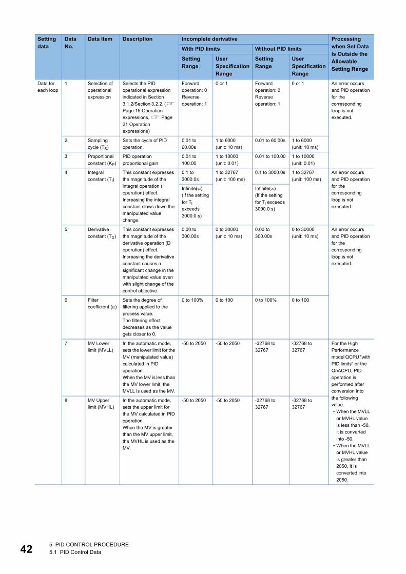
Data for
each loop
1 Selection of
operational
expression
Selects the PID
operational expression
indicated in Section
3.1.2/Section 3.2.2. (
Page 15 Operation
expressions, Page
21 Operation
expressions)
Forward
operation: 0
Reverse
operation: 1
0 or 1 Forward
operation: 0
Reverse
operation: 1
0 or 1 An error occurs
and PID operation
for the
corresponding
loop is not
executed.
2 Sampling
cycle (TS)
Sets the cycle of PID
operation.
0.01 to
60.00s
1 to 6000
(unit: 10 ms)
0.01 to 60.00s 1 to 6000
(unit: 10 ms)
3 Proportional
constant (KP)
PID operation
proportional gain
0.01 to
100.00
1 to 10000
(unit: 0.01)
0.01 to 100.00 1 to 10000
(unit: 0.01)
4 Integral
constant (TI)
This constant expresses
the magnitude of the
integral operation (I
operation) effect.
Increasing the integral
constant slows down the
manipulated value
change.
0.1 to
3000.0s
1 to 32767
(unit: 100 ms)
0.1 to 3000.0s 1 to 32767
(unit: 100 ms)
An error occurs
and PID operation
for the
corresponding
loop is not
executed.
Infinite()
(If the setting
for TI
exceeds
3000.0 s)
Infinite()
(If the setting
for TI exceeds
3000.0 s)
5 Derivative
constant (TD)
This constant expresses
the magnitude of the
derivative operation (D
operation) effect.
Increasing the derivative
constant causes a
significant change in the
manipulated value even
with slight change of the
control objective.
0.00 to
300.00s
0 to 30000
(unit: 10 ms)
0.00 to
300.00s
0 to 30000
(unit: 10 ms)
An error occurs
and PID operation
for the
corresponding
loop is not
executed.
6 Filter
coefficient ()
Sets the degree of
filtering applied to the
process value.
The filtering effect
decreases as the value
gets closer to 0.
0 to 100% 0 to 100 0 to 100% 0 to 100
7 MV Lower
limit (MVLL)
In the automatic mode,
sets the lower limit for the
MV (manipulated value)
calculated in PID
operation.
When the MV is less than
the MV lower limit, the
MVLL is used as the MV.
-50 to 2050 -50 to 2050 -32768 to
32767
-32768 to
32767
For the High
Performance
model QCPU "with
PID limits" or the
QnACPU, PID
operation is
performed after
conversion into
the following
value.
• When the MVLL
or MVHL value
is less than -50,
it is converted
into -50.
• When the MVLL
or MVHL value
is greater than
2050, it is
converted into
2050.
8 MV Upper
limit (MVHL)
In the automatic mode,
sets the upper limit for
the MV calculated in PID
operation.
When the MV is greater
than the MV upper limit,
the MVHL is used as the
MV.
-50 to 2050 -50 to 2050 -32768 to
32767
-32768 to
32767
Setting data
Data No.
Data Item Description Incomplete derivative Processing when Set Data is Outside the Allowable Setting Range
With PID limits Without PID limits
Setting Range
User Specification Range
Setting Range
User Specification Range
5 PID CONTROL PROCEDURE5.1 PID Control Data

5
Data for
each loop
9 MV change
rate limit (
MVL)
Sets the limit for variation
between the previous MV
and present MV.
When the MV variation is
greater than the limit
value, 1 is set for bit 1
(b1) of the alarm device.
Does not limit the MV
variation. (If the MV
variation is greater than
the limit value, it is used
unchanged as the MV
variation to calculate the
MV.)
0 to 2000 0 to 2000 -32768 to
32767
-32768 to
32767
In the case of
"with PID limits",
PID operation is
performed after
conversion into
the following
value.
• When the MVL
value is less
than 0, it is
converted into
0.
• When the MVL
value is greater
than 2000, it is
converted into
2000.
10 PV change
rate limit (
PVL)
Sets the limit for variation
between the previous PV
and present PV.
When the PV variation is
greater than the limit
value, 1 is set for bit 0
(b0) of the alarm device.
Does not limit the PV
variation. (If the PV
variation is greater than
the limit value, it is used
unchanged as the PV
variation to perform the
PID operation.)
0 to 2000 0 to 2000 -32768 to
32767
-32768 to
32767
In the case of
"with PID limits",
PID operation is
performed after
conversion into
the following
value.
• When the PVL
value is less
than 0, it is
converted into
0.
• When the PVL
value is greater
than 2000, it is
converted into
2000.
11 Derivative
gain (KD)
Sets a time period
(operation delay) for
derivative operation.
As the value is greater,
the time period
decreases and operation
becomes closer to
complete derivative.
0.00 to
300.00
(Ideal value
is 8.00)
0 to 32767
(unit: 0.01)
0.00 to 300.00
(Ideal value is
8.00)
0 to 32767
(unit: 0.01)
An error occurs
and PID operation
for the
corresponding
loop is not
executed.Infinite()
(If the setting
for KD
exceeds
300.00)
Infinite()
(If the setting
for KD
exceeds
300.00)
Setting data
Data No.
Data Item Description Incomplete derivative Processing when Set Data is Outside the Allowable Setting Range
With PID limits Without PID limits
Setting Range
User Specification Range
Setting Range
User Specification Range
5 PID CONTROL PROCEDURE5.1 PID Control Data 43
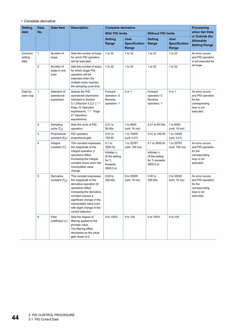
44
• Complete derivative
Setting data
Data No.
Data Item Description Complete derivative Processing when Set Data is Outside the Allowable Setting Range
With PID limits Without PID limits
Setting Range
User Specification Range
Setting Range
User Specification Range
Common
setting
data
1 Number of
loops
Sets the number of loops
for which PID operation
will be executed.
1 to 32 1 to 32 1 to 32 1 to 32 An error occurs
and PID operation
is not executed for
all loops.2 Number of
loops in one
scan
Sets the number of loops
for which single PID
operation will be
executed when the
multiple loops reaches
the sampling cycle time.
1 to 32 1 to 32 1 to 32 1 to 32
Data for
each loop
1 Selection of
operational
expression
Selects the PID
operational expression
indicated in Section
3.1.2/Section 3.2.2. (
Page 15 Operation
expressions, Page
21 Operation
expressions)
Forward
operation: 0
Reverse
operation: 1
0 or 1 Forward
operation: 0
Reverse
operation: 1
0 or 1 An error occurs
and PID operation
for the
corresponding
loop is not
executed.
2 Sampling
cycle (TS)
Sets the cycle of PID
operation.
0.01 to
60.00s
1 to 6000
(unit: 10 ms)
0.01 to 60.00s 1 to 6000
(unit: 10 ms)
3 Proportional
constant (KP)
PID operation
proportional gain
0.01 to
100.00
1 to 10000
(unit: 0.01)
0.01 to 100.00 1 to 10000
(unit: 0.01)
4 Integral
constant (TI)
This constant expresses
the magnitude of the
integral operation (I
operation) effect.
Increasing the integral
constant slows down the
manipulated value
change.
0.1 to
3000.0s
1 to 32767
(unit: 100 ms)
0.1 to 3000.0s 1 to 32767
(unit: 100 ms)
An error occurs
and PID operation
for the
corresponding
loop is not
executed.
Infinite()
(If the setting
for TI
exceeds
3000.0 s)
Infinite()
(If the setting
for TI exceeds
3000.0 s)
5 Derivative
constant (TD)
This constant expresses
the magnitude of the
derivative operation (D
operation) effect.
Increasing the derivative
constant causes a
significant change in the
manipulated value even
with slight change of the
control objective.
0.00 to
300.00s
0 to 30000
(unit: 10 ms)
0.00 to
300.00s
0 to 30000
(unit: 10 ms)
An error occurs
and PID operation
for the
corresponding
loop is not
executed.
6 Filter
coefficient ()
Sets the degree of
filtering applied to the
process value.
The filtering effect
decreases as the value
gets closer to 0.
0 to 100% 0 to 100 0 to 100% 0 to 100
5 PID CONTROL PROCEDURE5.1 PID Control Data
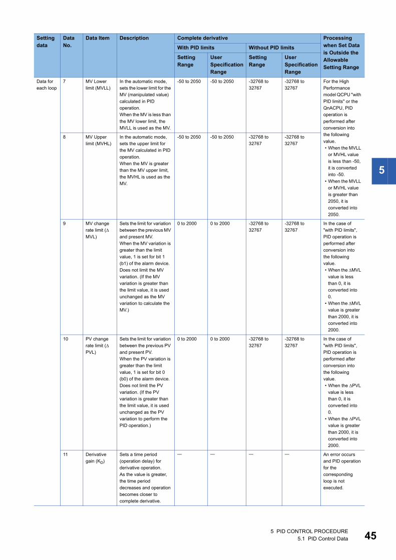
5
Data for
each loop
7 MV Lower
limit (MVLL)
In the automatic mode,
sets the lower limit for the
MV (manipulated value)
calculated in PID
operation.
When the MV is less than
the MV lower limit, the
MVLL is used as the MV.
-50 to 2050 -50 to 2050 -32768 to
32767
-32768 to
32767
For the High
Performance
model QCPU "with
PID limits" or the
QnACPU, PID
operation is
performed after
conversion into
the following
value.
• When the MVLL
or MVHL value
is less than -50,
it is converted
into -50.
• When the MVLL
or MVHL value
is greater than
2050, it is
converted into
2050.
8 MV Upper
limit (MVHL)
In the automatic mode,
sets the upper limit for
the MV calculated in PID
operation.
When the MV is greater
than the MV upper limit,
the MVHL is used as the
MV.
-50 to 2050 -50 to 2050 -32768 to
32767
-32768 to
32767
9 MV change
rate limit (
MVL)
Sets the limit for variation
between the previous MV
and present MV.
When the MV variation is
greater than the limit
value, 1 is set for bit 1
(b1) of the alarm device.
Does not limit the MV
variation. (If the MV
variation is greater than
the limit value, it is used
unchanged as the MV
variation to calculate the
MV.)
0 to 2000 0 to 2000 -32768 to
32767
-32768 to
32767
In the case of
"with PID limits",
PID operation is
performed after
conversion into
the following
value.
• When the MVL
value is less
than 0, it is
converted into
0.
• When the MVL
value is greater
than 2000, it is
converted into
2000.
10 PV change
rate limit (
PVL)
Sets the limit for variation
between the previous PV
and present PV.
When the PV variation is
greater than the limit
value, 1 is set for bit 0
(b0) of the alarm device.
Does not limit the PV
variation. (If the PV
variation is greater than
the limit value, it is used
unchanged as the PV
variation to perform the
PID operation.)
0 to 2000 0 to 2000 -32768 to
32767
-32768 to
32767
In the case of
"with PID limits",
PID operation is
performed after
conversion into
the following
value.
• When the PVL
value is less
than 0, it is
converted into
0.
• When the PVL
value is greater
than 2000, it is
converted into
2000.
11 Derivative
gain (KD)
Sets a time period
(operation delay) for
derivative operation.
As the value is greater,
the time period
decreases and operation
becomes closer to
complete derivative.
An error occurs
and PID operation
for the
corresponding
loop is not
executed.
Setting data
Data No.
Data Item Description Complete derivative Processing when Set Data is Outside the Allowable Setting Range
With PID limits Without PID limits
Setting Range
User Specification Range
Setting Range
User Specification Range
5 PID CONTROL PROCEDURE5.1 PID Control Data 45

46
■For QnACPU
Setting data
Data No.
Data Item Description Setting Range
User Specifi-cation Range
Processing when Set Data is Outside the Allowable Setting Range
Common
setting
data
1 Number of
loops
Sets the number of loops for which PID
operation will be executed.
1 to 32 1 to 32 An error occurs and PID operation is
not executed for all loops.
2 Number of
loops in one
scan
Sets the number of loops for which single
PID operation will be executed when the
multiple loops reaches the sampling cycle
time.
1 to 32 1 to 32
Data for
each loop
1 Selection of
operational
expression
Selects the PID operational expression
indicated in Section 3.2.2. ( Page 21
Operation expressions)
Forward
operation: 0
Reverse
operation: 1
0 or 1 An error occurs and PID operation for
the corresponding loop is not
executed.
2 Sampling
cycle (TS)
Sets the cycle of PID operation. 0.01 to
60.00s
1 to 6000
(unit: 10 ms)
3 Proportional
constant (KP)
PID operation ratio 0.01 to
100.00
1 to 10000
(unit: 0.01)
4 Integral
constant (TI)
This constant expresses the magnitude of
the integral operation (I operation) effect.
Increasing the integral constant slows
down the manipulated value change.
0.1 to
3000.0s
1 to 32767
(unit: 100 ms)
An error occurs and PID operation for
the corresponding loop is not
executed.Infinite()
(If the setting
for TI
exceeds
3000.0 s)
5 Derivative
constant (TD)
This constant expresses the magnitude of
the derivative operation (D operation)
effect.
Increasing the derivative constant causes
a significant change in the manipulated
value even with slight change of the
control objective.
0.00 to
300.00s
0 to 30000
(unit: 10 ms)
An error occurs and PID operation for
the corresponding loop is not
executed.
6 Filter
coefficient ()
Sets the degree of filtering applied to the
process value.
The filtering effect decreases as the value
gets closer to 0.
0 to 100% 0 to 100
7 MV Lower
limit (MVLL)
In the automatic mode, sets the lower limit
for the MV (manipulated value) calculated
in PID operation.
When the MV is less than the MV lower
limit, the MVLL is used as the MV.
-50 to 2050 -50 to 2050 PID operation is performed after
conversion into the following value.
• When the MVLL or MVHL value is
less than -50, it is converted into -
50.
• When the MVLL or MVHL value is
greater than 2050, it is converted
into 2050.
8 MV Upper
limit (MVHL)
In the automatic mode, sets the upper limit
for the MV calculated in PID operation.
When the MV is greater than the MV upper
limit, the MVHL is used as the MV.
-50 to 2050 -50 to 2050
9 MV change
rate limit (
MVL)
Sets the limit for variation between the
previous MV and present MV.
When the MV variation is greater than the
limit value, 1 is set for bit 1 (b1) of the
alarm device.
Does not limit the MV variation.
(If the MV variation is greater than the limit
value, it is used unchanged as the MV
variation to calculate the MV.)
0 to 2000 0 to 2000 PID operation is performed after
conversion into the following value.
• When the MVL value is less than
0, it is converted into 0.
• When the MVL value is greater
than 2000, it is converted into
2000.
10 PV change
rate limit (
PVL)
Sets the limit for variation between the
previous PV and present PV.
When the PV variation is greater than the
limit value, 1 is set for bit 0 (b0) of the
alarm device. Does not limit the PV
variation.
(If the PV variation is greater than the limit
value, it is used unchanged as the PV
variation to perform the PID operation.)
0 to 2000 0 to 2000 PID operation is performed after
conversion into the following value.
• When the PVL value is less than
0, it is converted into 0.
• When the PVL value is greater
than 2000, it is converted into
2000.
5 PID CONTROL PROCEDURE5.1 PID Control Data
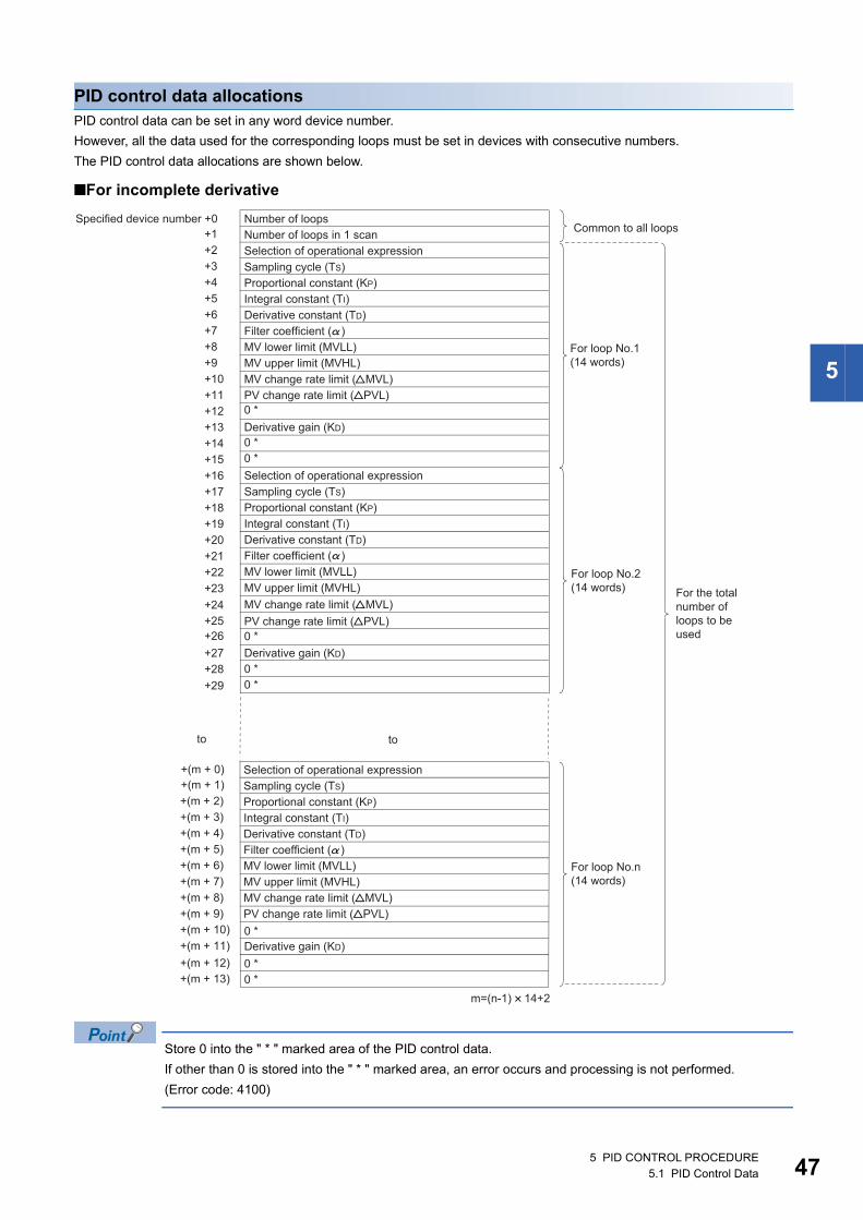
5
PID control data allocationsPID control data can be set in any word device number.
However, all the data used for the corresponding loops must be set in devices with consecutive numbers.
The PID control data allocations are shown below.
■For incomplete derivative
Store 0 into the " * " marked area of the PID control data.
If other than 0 is stored into the " * " marked area, an error occurs and processing is not performed.
(Error code: 4100)
5 PID CONTROL PROCEDURE5.1 PID Control Data 47
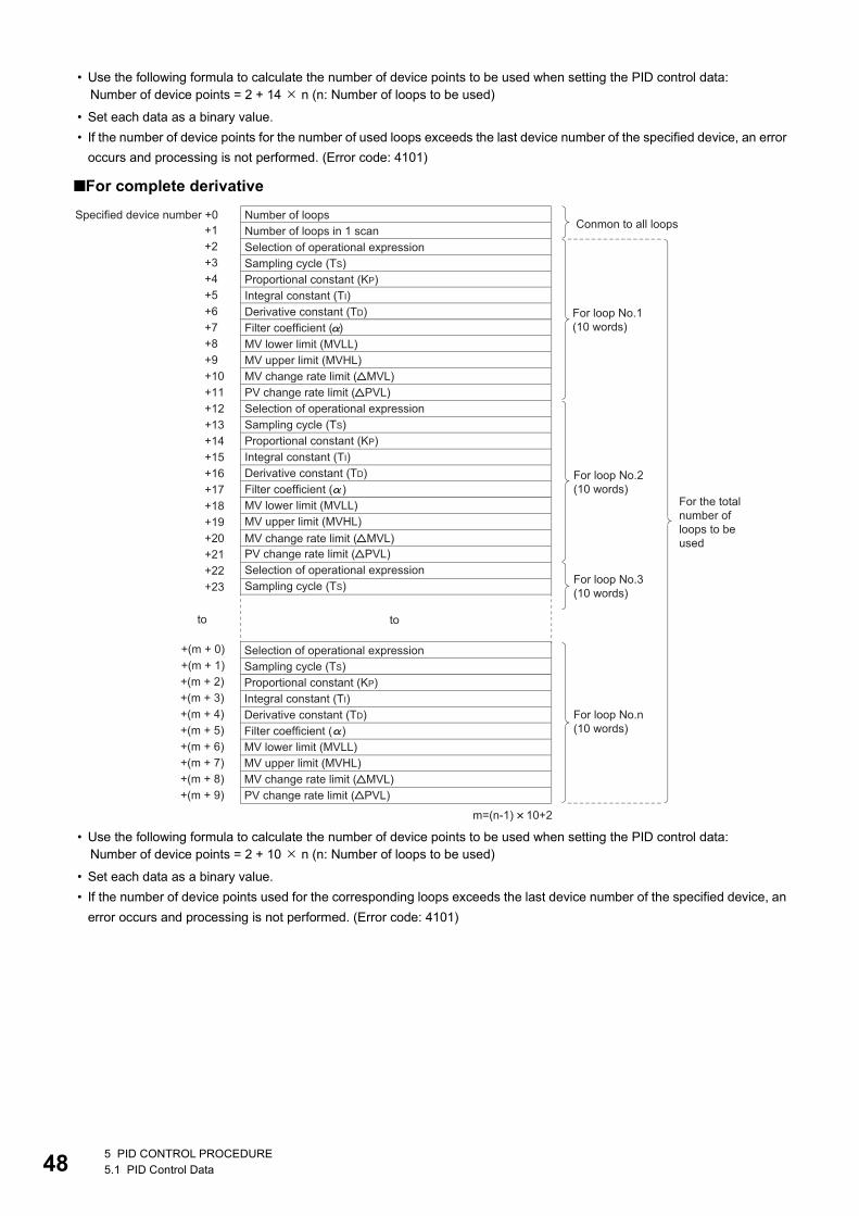
48
• Use the following formula to calculate the number of device points to be used when setting the PID control data:
• Set each data as a binary value.
• If the number of device points for the number of used loops exceeds the last device number of the specified device, an error
occurs and processing is not performed. (Error code: 4101)
■For complete derivative
• Use the following formula to calculate the number of device points to be used when setting the PID control data:
• Set each data as a binary value.
• If the number of device points used for the corresponding loops exceeds the last device number of the specified device, an
error occurs and processing is not performed. (Error code: 4101)
Number of device points = 2 + 14 n (n: Number of loops to be used)
Number of device points = 2 + 10 n (n: Number of loops to be used)
5 PID CONTROL PROCEDURE5.1 PID Control Data

5
Number of loops to be used and the number of loops to be executed in a single scan • The number of loops to be used means the number of loops for which PID operation is executed. The sampling cycle time
is measured for the set number of loops when the PID operation instruction*1 is executed. PID operation is executed for the
loop for which the sampling cycle time reaches or exceeds the set sampling cycle.
• Processing time increases in proportion to the number of loops for which PID operation is executed when the PID operation
instruction is executed.
• The number of loops to be executed in a single scan means the number of loops for which PID operation is executed in one
scan when there is more than one loop for which sampling cycle time reaches or exceeds the set sampling cycle when the
PID operation instruction is executed. If the number of loops to be executed in a single scan is set, PID operation is only
executed for the set number of loops even if there are a greater number of loops for which the sampling cycle time reaches
or exceeds the set sampling cycle when the PID operation instruction is executed. PID operation is executed for the rest of
the loops in the next scan.
If the number of loops for which sampling cycle time reaches or exceeds the set sampling cycle is greater than
the number of loops to be executed in a single scan, the PID operation execution priority is as follows:
• The lowest numbered loop is given the highest priority.
• If there are loops in the preceding scan for which PID operation has not been executed, they are given the
highest priority.
*1 The following instructions are available as the PID operation instructions.S.PIDCONT (incomplete derivative)PIDCONT (complete derivative)
Operational expression Meaning of symbols
Processing time = A + B n A: Fixed time for measuring sampling time
B: Time required to execute PID operation for a loop
n = Number of loops
5 PID CONTROL PROCEDURE5.1 PID Control Data 49
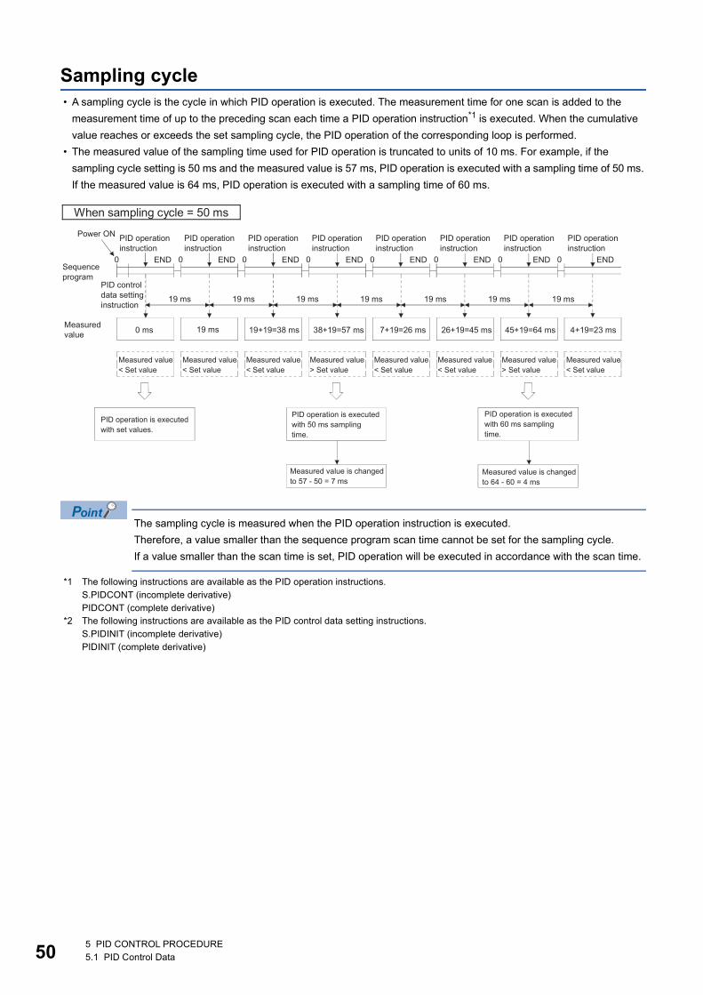
50
Sampling cycle • A sampling cycle is the cycle in which PID operation is executed. The measurement time for one scan is added to the
measurement time of up to the preceding scan each time a PID operation instruction*1 is executed. When the cumulative
value reaches or exceeds the set sampling cycle, the PID operation of the corresponding loop is performed.
• The measured value of the sampling time used for PID operation is truncated to units of 10 ms. For example, if the
sampling cycle setting is 50 ms and the measured value is 57 ms, PID operation is executed with a sampling time of 50 ms.
If the measured value is 64 ms, PID operation is executed with a sampling time of 60 ms.
The sampling cycle is measured when the PID operation instruction is executed.
Therefore, a value smaller than the sequence program scan time cannot be set for the sampling cycle.
If a value smaller than the scan time is set, PID operation will be executed in accordance with the scan time.
*1 The following instructions are available as the PID operation instructions.S.PIDCONT (incomplete derivative)PIDCONT (complete derivative)
*2 The following instructions are available as the PID control data setting instructions.S.PIDINIT (incomplete derivative)PIDINIT (complete derivative)
5 PID CONTROL PROCEDURE5.1 PID Control Data

5
5.2 I/O DataThe I/O data consists of input data, such as the SV (set value) and PV (process value), which are set to execute PID
operation, and output data, such as operation results.
The I/O data area is divided into the "data area where data are allocated loop-by-loop" and "work area used by the system to
perform PID operation".
I/O Data List
■QCPU, LCPU
Data Name Description Setting Range Processing when Set Data is Outside the Specified Range
With PID limits Without PID limits
Set value SV PID control target value 0 to 2000 -32768 to 32767 For the QCPU or LCPU with
"With PID limits" setting or
QnACPU, convert it to the
following value for PID
operation.
When SV is less than 0, SV
must be 0.
When SV is greater than
2000, SV must be 2000.
Process value PV Feedback data from
controlled system objective to
A/D converter module
-50 to 2050 -32768 to 32767 For the QCPU or LCPU with
"With PID limits" setting or
QnACPU, convert it to the
following value for PID
operation.
• When PV is less than -50,
PV must be -50.
• When PV is greater than
2050, PV must be 2050.
Automatic
manipulated
value
MV The manipulated value
calculated by PID operation.
Output from the D/A
converter module to the
controlled system.
-50 to 2050 -32768 to 32767
Process value
after filtering
PVf Process value calculated
using the operation formula
in POINT(1) in Section 3.1.2/
POINT(1) in Section 3.2.2.
( Page 15 Operation
expressions, Page 21
Operation expressions)
-50 to 2050 -32768 to 32767
Manual
manipulated
value
MVMAN In the manual control mode,
the data output from the D/A
converter module is stored.
-50 to 2050 -32768 to 32767 For the QCPU or LCPU with
"With PID limits" setting or
QnACPU, convert it to the
following value for PID
operation.
• When MVMAN is less than -
50, MVMAN must be -50.
• When MVMAN is greater
than 2050, MVMAN must be
2050.
Manual/
automatic
selection
MAN/
AUTO
Selects whether the output
data to the D/A converter
module is shown as a manual
manipulated value or an
automatic manipulated value.
In manual control mode, the
automatic manipulated value
remains unchanged.
0: Manual manipulated value
1: Automatic manipulated
value
0: Manual manipulated value
1: Automatic manipulated
value
An error occurs if the setting
is neither 0 nor 1, and PID
operation of the
corresponding loop will not
be executed.
5 PID CONTROL PROCEDURE5.2 I/O Data 51

52
■QnACPU
Alarm ALARM Used to determine if the
change rate of the MV
(manipulated value) and the
PV (process value) is within
or outside the allowable
range.
Once set, the alarm data is
retained until the user resets
it.
If the MV is outside the limit
range, "1" is set for bit 1 (b1).
If the PV is outside the limit
range, "1" is set for bit 0 (b0).
Data Name Description Setting Range Processing when Set Data is Outside the Specified Range
Set value SV PID control target value 0 to 2000 For the QCPU or LCPU with "With PID limits"
setting or QnACPU, convert it to the following
value for PID operation.
• When SV is less than 0, SV must be 0.
• When SV is greater than 2000, SV must be
2000.
Process value PV Feedback data from controlled system
objective to A/D converter module
-50 to 2050 For the QCPU or LCPU with "With PID limits"
setting or QnACPU, convert it to the following
value for PID operation.
• When PV is less than -50, PV must be -50.
• When PV is greater than 2050, PV must be
2050.
Automatic
manipulated
value
MV The manipulated value calculated by PID
operation.
Output from the D/A converter module to the
controlled system.
-50 to 2050
Process value
after filtering
PVf Process value calculated using the operation
formula in POINT(1) in Section 3.1.2/
POINT(1) in Section 3.2.2. ( Page 15
Operation expressions, Page 21
Operation expressions)
-50 to 2050
Manual
manipulated
value
MVMAN In the manual control mode, the data output
from the D/A converter module is stored.
-50 to 2050 For the QCPU or LCPU with "With PID limits"
setting or QnACPU, convert it to the following
value for PID operation.
• When MVMAN is less than -50, MVMAN must
be -50.
• When MVMAN is greater than 2050, MVMAN
must be 2050.
Manual/
automatic
selection
MAN/
AUTO
Selects whether the output data to the D/A
converter module is shown as a manual
manipulated value or an automatic
manipulated value.
In manual control mode, the automatic
manipulated value remains unchanged.
0: Manual manipulated value
1: Automatic manipulated
value
An error occurs if the setting is neither 0 nor 1,
and PID operation of the corresponding loop
will not be executed.
Alarm ALARM Used to determine if the change rate of the
MV (manipulated value) and the PV (process
value) is within or outside the allowable range.
Once set, the alarm data is retained until the
user resets it.
If the MV is outside the limit range, "1" is set
for bit 1 (b1).
If the PV is outside the limit range, "1" is set
for bit 0 (b0).
Data Name Description Setting Range Processing when Set Data is Outside the Specified Range
With PID limits Without PID limits
5 PID CONTROL PROCEDURE5.2 I/O Data
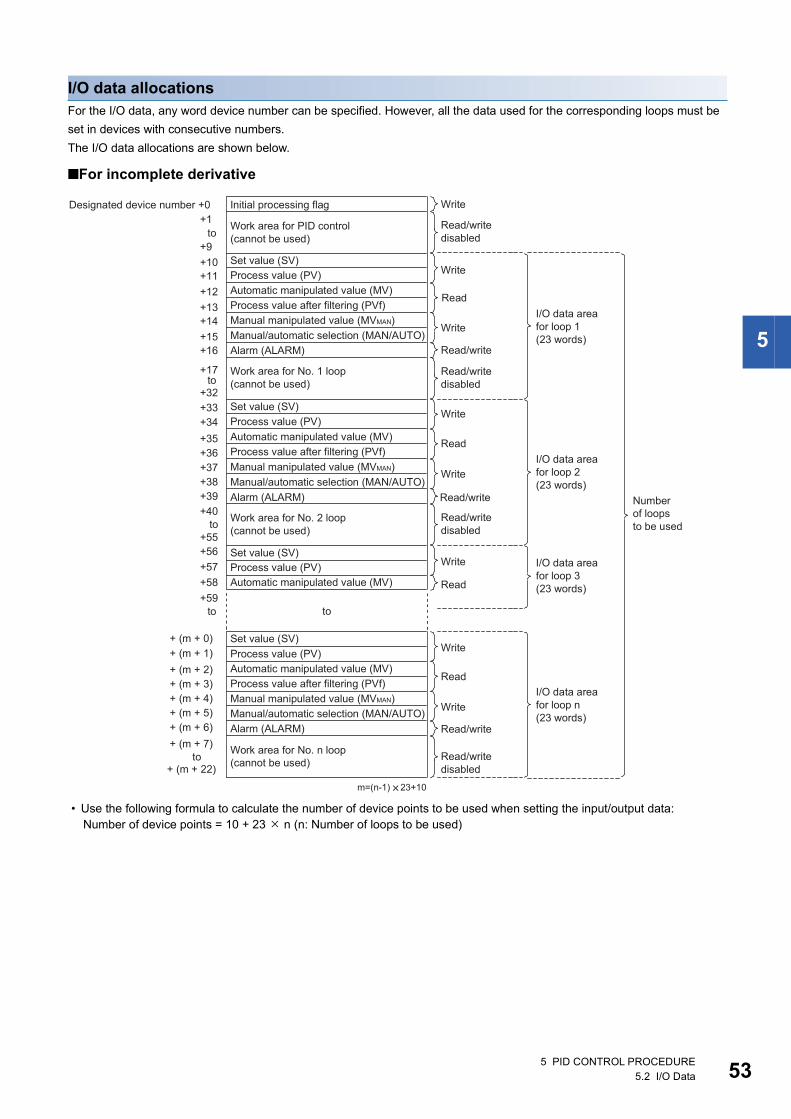
5
I/O data allocationsFor the I/O data, any word device number can be specified. However, all the data used for the corresponding loops must be
set in devices with consecutive numbers.
The I/O data allocations are shown below.
■For incomplete derivative
• Use the following formula to calculate the number of device points to be used when setting the input/output data:Number of device points = 10 + 23 n (n: Number of loops to be used)
5 PID CONTROL PROCEDURE5.2 I/O Data 53

54
• Set each data as a binary value.
• The initial processing flag sets the processing method at the start of PID operation. In the initial PID operation processing
cycle, operation is executed assuming that the set sampling cycle is reached or exceeded. The initial processing flag is set
in the following manner:
• Where "write" is designated for a data area, it indicates that the data should be written with a user sequence program.
Where "read" is designated for a data area, it indicates that the data should be read with a user sequence program. Never
attempt to write data to a data area designated "read/write disabled" or "read". If this is attempted, correct PID operation will
not be possible. Note that when control is to be started from the initial status, data must be cleared with a sequence
program.
• If the number of device points used for the corresponding loops exceeds the last device number of the specified device, an
error occurs and processing is not performed. (Error code: 4101)
■For complete derivative
Set value Description
0 PID operation is batch processed in a single scan for the number of loops to be used.
Other than 0 PID operation is processed in several scans for the number of loops to be used.
Sampling begins sequentially from the loop for which the initial processing has been completed.
The number of processing loops per scan is the set number of loops to be executed per scan.
5 PID CONTROL PROCEDURE5.2 I/O Data

5
• Use the following formula to calculate the number of device points to be used when setting the I/O data:
• Set each data as a binary value.
• The initial processing flag sets the processing method at the start of PID operation. In the initial PID operation processing
cycle, operation is executed assuming that the set sampling cycle is reached or exceeded. The initial processing flag is set
in the following manner:
• Where "write" is designated for a data area, it indicates that the data should be written with a user sequence program.
Where "read" is designated for a data area, it indicates that the data should be read with a user sequence program. Never
attempt to write data to a data area designated "read/write disabled" or "read". If this is attempted, correct PID operation will
not be possible. Note that when control is to be started from the initial status, data must be cleared with a sequence
program.
• If the number of device points for the number of used loops exceeds the last device number of the specified device, an error
occurs and processing is not performed. (Error code: 4101)
Number of device points = 10 + 18 n (n: Number of loops to be used)
Set value Description
0 PID operation is batch processed in a single scan for the number of loops to be used.
Other than 0 PID operation is processed in several scans for the number of loops to be used.
Sampling begins sequentially from the loop for which the initial processing has been completed.
The number of processing loops per scan is the set number of loops to be executed per scan.
5 PID CONTROL PROCEDURE5.2 I/O Data 55

56
6 PID CONTROL INSTRUCTIONS
The structure of PID control instructions is the same as that of common instructions for the Basic model QCPU, High
Performance model QCPU, Redundant CPU, Universal model QCPU, LCPU, and QnACPU.
For details on the configuration of control instructions, see the QCPU (Q mode)/QnACPU Programming Manual (Common
Instructions.)
6 PID CONTROL INSTRUCTIONS

6
MEMO
6 PID CONTROL INSTRUCTIONS 57
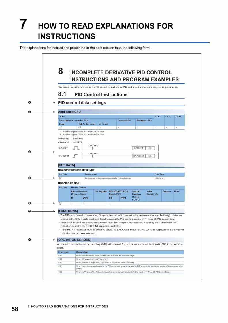
58
7 HOW TO READ EXPLANATIONS FOR INSTRUCTIONS
The explanations for instructions presented in the next section take the following form.
�
�
�
�
�
�
�
7 HOW TO READ EXPLANATIONS FOR INSTRUCTIONS
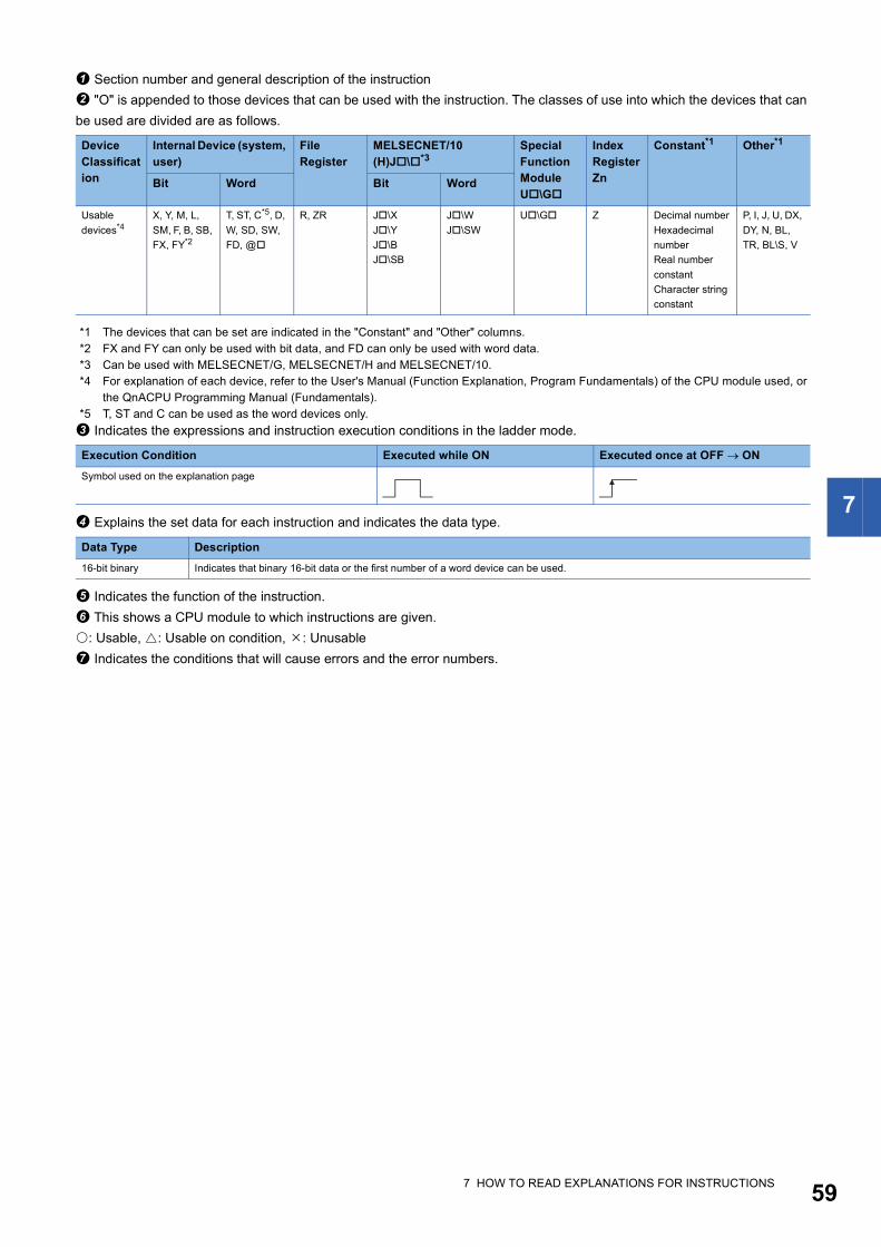
7
Section number and general description of the instruction
"O" is appended to those devices that can be used with the instruction. The classes of use into which the devices that can
be used are divided are as follows.
*1 The devices that can be set are indicated in the "Constant" and "Other" columns.*2 FX and FY can only be used with bit data, and FD can only be used with word data.*3 Can be used with MELSECNET/G, MELSECNET/H and MELSECNET/10.*4 For explanation of each device, refer to the User's Manual (Function Explanation, Program Fundamentals) of the CPU module used, or
the QnACPU Programming Manual (Fundamentals).*5 T, ST and C can be used as the word devices only.
Indicates the expressions and instruction execution conditions in the ladder mode.
Explains the set data for each instruction and indicates the data type.
Indicates the function of the instruction.
This shows a CPU module to which instructions are given.
: Usable, : Usable on condition, : Unusable
Indicates the conditions that will cause errors and the error numbers.
Device Classification
Internal Device (system, user)
File Register
MELSECNET/10 (H)J\*3
Special Function Module U\G
Index Register Zn
Constant*1 Other*1
Bit Word Bit Word
Usable
devices*4X, Y, M, L,
SM, F, B, SB,
FX, FY*2
T, ST, C*5, D,
W, SD, SW,
FD, @
R, ZR J\X
J\Y
J\B
J\SB
J\W
J\SW
U\G Z Decimal number
Hexadecimal
number
Real number
constant
Character string
constant
P, I, J, U, DX,
DY, N, BL,
TR, BL\S, V
Execution Condition Executed while ON Executed once at OFF ON
Symbol used on the explanation page
Data Type Description
16-bit binary Indicates that binary 16-bit data or the first number of a word device can be used.
7 HOW TO READ EXPLANATIONS FOR INSTRUCTIONS 59
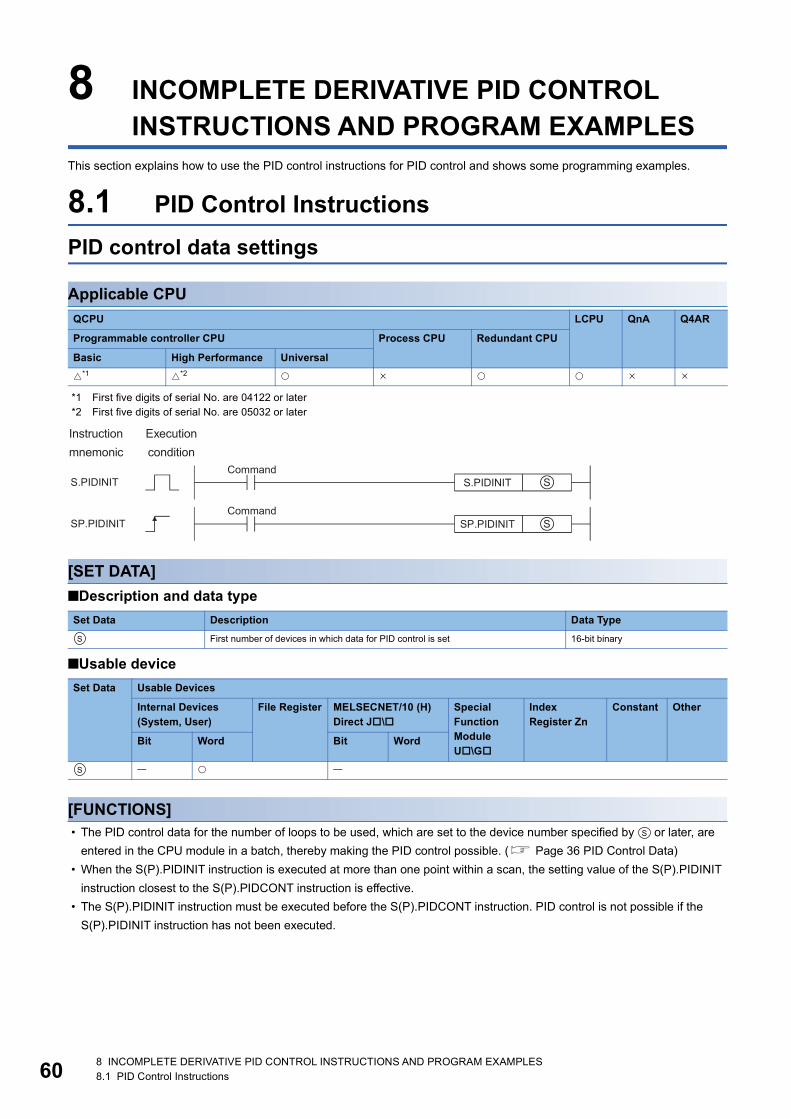
60
8 INCOMPLETE DERIVATIVE PID CONTROL INSTRUCTIONS AND PROGRAM EXAMPLES
This section explains how to use the PID control instructions for PID control and shows some programming examples.
8.1 PID Control Instructions
PID control data settings
Applicable CPU
*1 First five digits of serial No. are 04122 or later*2 First five digits of serial No. are 05032 or later
[SET DATA]
■Description and data type
■Usable device
[FUNCTIONS] • The PID control data for the number of loops to be used, which are set to the device number specified by or later, are
entered in the CPU module in a batch, thereby making the PID control possible. ( Page 36 PID Control Data)
• When the S(P).PIDINIT instruction is executed at more than one point within a scan, the setting value of the S(P).PIDINIT
instruction closest to the S(P).PIDCONT instruction is effective.
• The S(P).PIDINIT instruction must be executed before the S(P).PIDCONT instruction. PID control is not possible if the
S(P).PIDINIT instruction has not been executed.
QCPU LCPU QnA Q4AR
Programmable controller CPU Process CPU Redundant CPU
Basic High Performance Universal
*1 *2
Set Data Description Data Type
First number of devices in which data for PID control is set 16-bit binary
Set Data Usable Devices
Internal Devices (System, User)
File Register MELSECNET/10 (H) Direct J\
Special Function Module U\G
Index Register Zn
Constant Other
Bit Word Bit Word
S
S
S
8 INCOMPLETE DERIVATIVE PID CONTROL INSTRUCTIONS AND PROGRAM EXAMPLES8.1 PID Control Instructions

8
[OPERATION ERRORS]An operation error will occur, the error flag (SM0) will be turned ON, and an error code will be stored in SD0, in the following
cases.
PID operation
Applicable CPU
*1 First five digits of serial No. are 04122 or later*2 First five digits of serial No. are 05032 or later
[SET DATA]
■Description and data type
■Usable device
Error code Description
4100 When the value set as the PID control data is outside the allowable range.
4100 When (MV upper limit) < (MV lower limit).
4100 When (Number of loops used) < (Number of loops executed in one scan).
4101 When the device range allocated to the PID control data area, designated by , exceeds the last device number of the corresponding
device.
4100 When the "*" area of the PID control data that is mentioned in section 5.1 (3) is not 0. ( Page 36 PID Control Data)
QCPU LCPU QnA Q4AR
Programmable controller CPU Process CPU Redundant CPU
Basic High Performance Universal
*1 *2
Set Data Description Data Type
First number of devices allocated to I/O device area 16-bit binary
Set Data Usable Devices
Internal Devices (System, User)
File Register MELSECNET/10 (H) Direct J\
Special Function Module U\
Index Register Zn
Constant Other
Bit Word Bit Word
S
S
S
8 INCOMPLETE DERIVATIVE PID CONTROL INSTRUCTIONS AND PROGRAM EXAMPLES8.1 PID Control Instructions 61

62
[FUNCTION] • When the S(P).PIDCONT instruction is executed, the sampling cycle is measured and PID operation is performed.
• With the S(P).PIDCONT instruction, PID operation is carried out on the basis of the set value (SV) and process value (PV)
in the I/O data area set to the device number specified by or later, and the operation result is stored into the
automatically manipulated value (MV) area of the I/O data area.
• PID operation is executed in response to the execution of the S(P).PIDCONT instruction appearing first after the set time
for sampling cycle has elapsed. ( Page 50 Sampling cycle)
• During PID control, turn ON the control command to execute the S(P).PIDCONT instruction in every scan. If not, PID
operation in a normal sampling cycle will not available. It is not possible to execute the S(P).PIDCONT instruction more
than once in one scan. If it is executed more than once in one scan, PID operation cannot be performed in a normal
sampling cycle.
• The S(P).PIDCONT instruction is not available for use in an interrupt program, fixed scan execution type program or low
speed execution type program. If the S(P).PIDCONT instruction has been used in an interrupt program, fixed scan
execution type program or low speed execution type program, PID operation cannot be performed in a normal sampling
cycle.
• For , designate the first number of the device numbers that are designated in the I/O data area. If file registers (R) are
designated for the I/O data area, do not set memory protect ON for the file registers (R). If memory protect is set ON,
correct PID operation will be precluded, although no error will occur. ( Page 51 I/O Data)
• Execute the S(P).PIDCONT instruction in every scan even while the manual manipulated value (MVMAN) is being output in
the manual control mode. The bumpless switching cannot be executed if the S(P).PIDCONT instruction has not been
executed. ( Page 31 Bumpless changeover function)
• Use the READY signal to establish an interlock with respect to the individual modules, so that the S(P).PIDCONT
instruction is executed only when both the A/D converter module for reading the PV (process value) and the D/A converter
module for outputting the MV (manipulated value) are normal. If the S(P).PIDCONT instruction is executed while either or
both of the modules are faulty, PID operation cannot be executed correctly because the PV (process value) cannot be read
correctly and/or the MV (manipulated value) cannot be output correctly.
[OPERATION ERRORS]An operation error will occur, the error flag (SM0) will be turned ON, and an error code will be stored in SD0, in the following
cases.
For details on the READY signals of the A/D converter module and D/A converter module, refer to the manual for the relevant
module.
Error code Description
4103 When the S(P).PIDINIT instruction is not executed before executing the S(P).PIDCONT instruction.
4100 When the value set as the PID control data is outside the allowable range.
4101 When the device range allocated to the PID control data area, designated with , exceeds the last device number of the corresponding
device.
S
S
S
8 INCOMPLETE DERIVATIVE PID CONTROL INSTRUCTIONS AND PROGRAM EXAMPLES8.1 PID Control Instructions

8
Operation stop/start of designated loop no.
Applicable CPU
*1 First five digits of serial No. are 04122 or later*2 First five digits of serial No. are 05032 or later
[SET DATA]
■Description and data type
■Usable device
[FUNCTION]
■S.PIDSTOP, SP.PIDSTOP • Stops the PID operation for the loop number designated by (n). The loop stopped by the S(P).PIDSTOP instruction does
not resume PID operation even if the S(P).PIDINIT instruction is executed.
• Retains the operation data during the stop.
■S.PIDRUN, SP.PIDRUN • Starts the PID operation of the loop No. specified by (n). This instruction is designed to re-execute PID operation of the loop
No. that has stopped with the S(P).PIDSTOP instruction.
• This instruction will be ignored if the instruction is executed for the loop No. that is currently running PID operation.
[OPERATION ERRORS]An operation error will occur and the error flag (SM0) will be turned ON in the following cases.
QCPU LCPU QnA Q4AR
Programmable controller CPU Process CPU Redundant CPU
Basic High Performance Universal
*1 *2
Set Data Description Data Type
(n) Loop number at which start/stop is to be executed 16-bit binary
Set Data Usable Devices
Internal Devices (System, User)
File Register MELSECNET/10 (H) Direct J\
Special Function Module U\G
Index Register Zn
Constant K, H
Other
Bit Word Bit Word
(n)
Error code Description
4100 When the loop number designated by (n) does not exist.
4100 When (n) is outside the range 1 to 8. (Basic model QCPU)
4100 When (n) is any other than 1 to 32. (High Performance model QCPU, Redundant CPU, Universal model QCPU, LCPU)
4103 When the S(P).PIDINIT and S(P).PIDCONT instructions have not been executed before execution of the S(P).PIDSTOP instruction.
4103 When the S(P).PIDINIT and S(P).PIDCONT instructions have not been executed before execution of the S(P).PIDRUN instruction.
8 INCOMPLETE DERIVATIVE PID CONTROL INSTRUCTIONS AND PROGRAM EXAMPLES8.1 PID Control Instructions 63
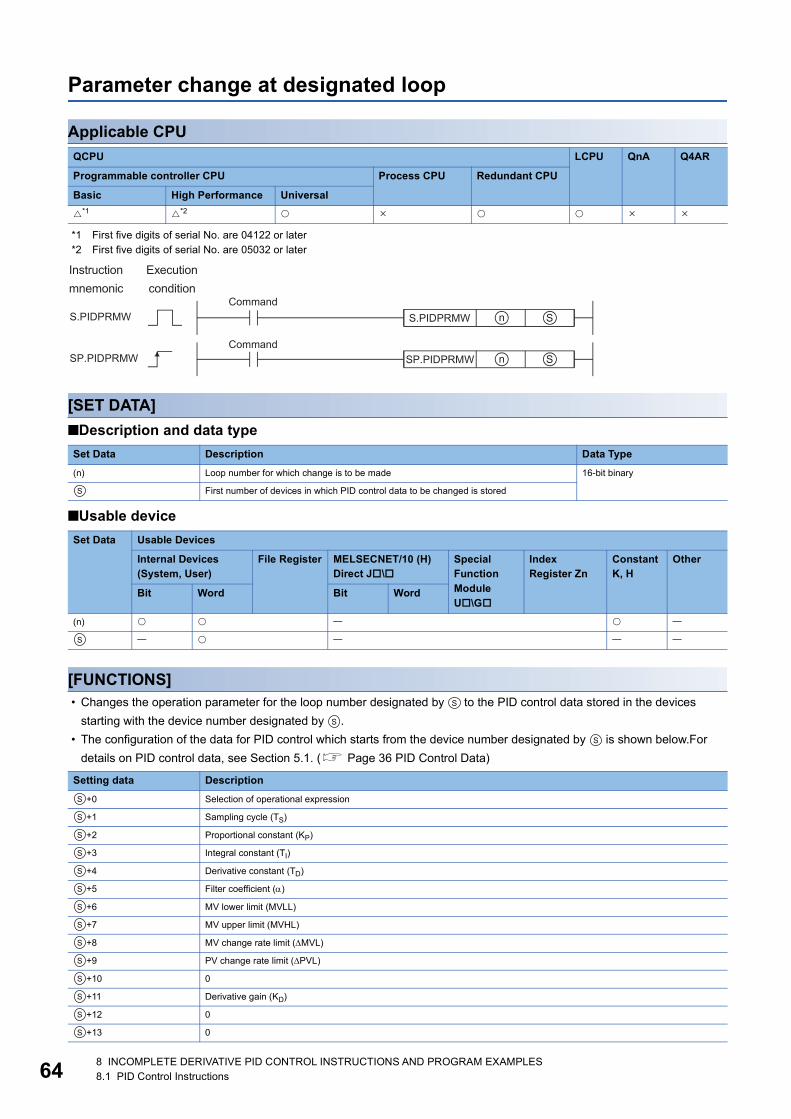
64
Parameter change at designated loop
Applicable CPU
*1 First five digits of serial No. are 04122 or later*2 First five digits of serial No. are 05032 or later
[SET DATA]
■Description and data type
■Usable device
[FUNCTIONS] • Changes the operation parameter for the loop number designated by to the PID control data stored in the devices
starting with the device number designated by .
• The configuration of the data for PID control which starts from the device number designated by is shown below.For
details on PID control data, see Section 5.1. ( Page 36 PID Control Data)
QCPU LCPU QnA Q4AR
Programmable controller CPU Process CPU Redundant CPU
Basic High Performance Universal
*1 *2
Set Data Description Data Type
(n) Loop number for which change is to be made 16-bit binary
First number of devices in which PID control data to be changed is stored
Set Data Usable Devices
Internal Devices (System, User)
File Register MELSECNET/10 (H) Direct J\
Special Function Module U\G
Index Register Zn
Constant K, H
Other
Bit Word Bit Word
(n)
Setting data Description
+0 Selection of operational expression
+1 Sampling cycle (TS)
+2 Proportional constant (KP)
+3 Integral constant (TI)
+4 Derivative constant (TD)
+5 Filter coefficient ()
+6 MV lower limit (MVLL)
+7 MV upper limit (MVHL)
+8 MV change rate limit (MVL)
+9 PV change rate limit (PVL)
+10 0
+11 Derivative gain (KD)
+12 0
+13 0
S
S
S
S
S
S
S
S
S
S
S
S
S
S
S
S
S
S
S
8 INCOMPLETE DERIVATIVE PID CONTROL INSTRUCTIONS AND PROGRAM EXAMPLES8.1 PID Control Instructions

8
[OPERATION ERRORS]An operation error will occur and the error flag (SM0) will be turned ON, and error code will be stored in SD0, in the following
cases.
Error code Description
4100 When the loop number designated by (n) does not exist.
4100 When (n) is outside the range 1 to 8. (Basic model QCPU)
4100 When (n) is any other than 1 to 32. (High Performance model QCPU, Redundant CPU, Universal model QCPU, LCPU)
4100 When the PID control data is outside the setting range.
4100 When any of + 10, + 12 and + 13 in the PID control data is not 0.
4101 When the device range assigned to the PID control data area by exceeds the last device number of the applicable range.
4103 When the S(P).PIDINIT instruction has not been executed before execution of the S(P).PIDPRMW instruction.
S S S
S
8 INCOMPLETE DERIVATIVE PID CONTROL INSTRUCTIONS AND PROGRAM EXAMPLES8.1 PID Control Instructions 65

66
8.2 PID Control Program ExamplesThis section describes examples of sequence programs that execute PID control.
System configuration for program examplesThe following illustrates the system configuration for the program examples.
Program example for automatic mode PID controlThis section gives a program example in which PID operation is performed using the digital values imported from the Q64AD
as PV and the MV obtained as a result of PID operation are output from the Q62DA to control external devices.
[PROGRAMMING CONDITIONS] • PID operation is executed for 2 loops.
• The sampling cycle is 1 second.
• The PID control data is set in the following devices: ( Page 36 PID Control Data)
• The I/O data is set in the following devices: ( Page 51 I/O Data)
• The following SV are set for loop 1 and loop 2 using a sequence program:
• The following devices are used for PID control start/stop commands.
• The digital values of the Q64AD and Q62DA are set within the range 0 to 2000.
Module I/O number
Q64AD X/Y80 to X/Y8F
Q62DA X/YA0 to X/YAF
PID control data Device name
Common data D500 to D501
Loop 1 data D502 to D515
Loop 2 data D516 to D529
I/O data Device name
Common data D600 to D609
Loop 1 data D610 to D632
Loop 2 data D633 to D655
Loop SV
Loop 1 600
Loop 2 1000
Command Device name
PID control start command X0
PID control stop command X1
8 INCOMPLETE DERIVATIVE PID CONTROL INSTRUCTIONS AND PROGRAM EXAMPLES8.2 PID Control Program Examples
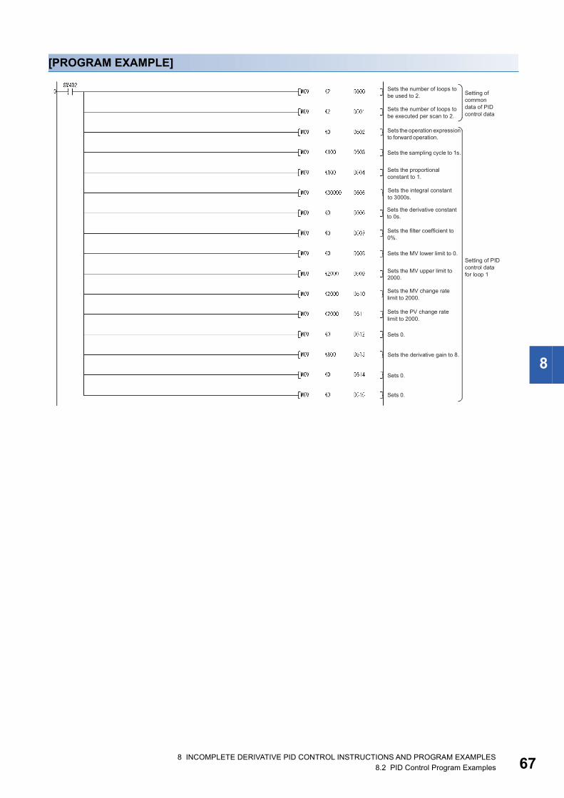
8
[PROGRAM EXAMPLE]
8 INCOMPLETE DERIVATIVE PID CONTROL INSTRUCTIONS AND PROGRAM EXAMPLES8.2 PID Control Program Examples 67
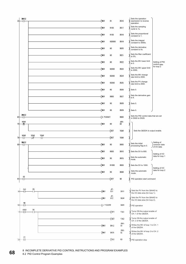
68
8 INCOMPLETE DERIVATIVE PID CONTROL INSTRUCTIONS AND PROGRAM EXAMPLES8.2 PID Control Program Examples
8
Program example for changing the PID control mode between automatic and manualAn example program for switching between automatic and manual modes while executing PID operation is described below.
[PROGRAMMINGCONDITIONS] • PID operation is executed for 1 loop.
• The sampling cycle is 1 second.
• The PID control data is set in the following devices:
• The I/O data is set in the following devices:
• The SV and MV in manual mode are set with external digital switches as follows:
• The following devices are used to start and stop PID control and the automatic/manual changeover command:
• The digital values of the Q64AD and Q62DA are set within the range 0 to 2000.
• The PID bumpless processing flag, SM794, is set to OFF. In the manual mode, the SV is automatically rewritten to the PV
when PID operation is performed. Therefore, when the manual mode is returned to the automatic mode, the SV must be
rewritten to the one used in the automatic mode before switching to the manual mode. The SV is rewritten step-by-step 10
times as illustrated below:*1
*1 The SV is rewritten using the operation method illustrated below:
The incremental value obtained with the formula above is added to SV every second. The remainder is added in the first addition operation.
PID control data Device name
Common data D500 to D501
Loop 1 data D502 to D515
I/O data Device name
Common data D600 to D609
Loop 1 data D610 to D632
Item Device name
SV X30 to X3F
MV (manual control mode) X20 to X2F
Command Device name
PID control start command X0
PID control stop command X1
SV setting command X3
MV setting command in manual mode X4
Automatic/manual mode changeover command X6 (OFF: Automatic mode, ON: Manual mode)
8 INCOMPLETE DERIVATIVE PID CONTROL INSTRUCTIONS AND PROGRAM EXAMPLES8.2 PID Control Program Examples 69

70
[PROGRAM EXAMPLE]
8 INCOMPLETE DERIVATIVE PID CONTROL INSTRUCTIONS AND PROGRAM EXAMPLES8.2 PID Control Program Examples

8
8 INCOMPLETE DERIVATIVE PID CONTROL INSTRUCTIONS AND PROGRAM EXAMPLES8.2 PID Control Program Examples 71

72
9 COMPLETE DERIVATIVE PID CONTROL INSTRUCTIONS AND PROGRAM EXAMPLES
This chapter explains the PID control instruction usage and program examples for implementing PID control.
9.1 PID Control Instructions
PID control data settings
Applicable CPU
*1 First five digits of serial No. are 04122 or later
[SET DATA]
■Description and data type
■Usable device
[FUNCTIONS] • The PID control data for the number of loops to be used, which are set to the device number specified by or later, are
entered in the CPU module in a batch, thereby making the PID control possible. ( Page 36 PID Control Data)
• When the PIDINIT(P) instruction is executed at more than one point within a scan, the setting value of the PIDINIT(P)
instruction closest to the PIDCONT(P) instruction is effective.
• The PIDINIT(P) instruction must be executed before the PIDCONT(P) instruction. PID control is not possible if the
PIDINIT(P) instruction has not been executed.
QCPU LCPU QnA Q4AR
Programmable controller CPU Process CPU Redundant CPU
Basic High Performance Universal
*1
Set Data Description Data Type
First number of devices in which data for PID control is set 16-bit binary
Set Data Usable Devices
Internal Devices (System, User)
File Register MELSECNET/10 (H) Direct J\
Special Function Module U\G
Index Register Zn
Constant Other
Bit Word Bit Word
S
S
S
9 COMPLETE DERIVATIVE PID CONTROL INSTRUCTIONS AND PROGRAM EXAMPLES9.1 PID Control Instructions

9
[OPERATION ERRORS]An operation error will occur, the error flag (SM0) will be turned ON, and an error code will be stored in SD0, in the followingcases.
Error code Description
4100 When the value set as the PID control data is outside the allowable range.
4100 When (Number of loops used) < (Number of loops executed in one scan).
4100 When (MV upper limit value) < (MV lower limit value).
4101 When the device range allocated to the PID control data area, designated by , exceeds the last device number of the corresponding
device.
S
9 COMPLETE DERIVATIVE PID CONTROL INSTRUCTIONS AND PROGRAM EXAMPLES9.1 PID Control Instructions 73

74
PID control
Applicable CPU
*1 First five digits of serial No. are 04122 or later
[SET DATA]
■Description and data type
■Usable device
[FUNCTION] • When the PIDCONT(P) instruction is executed, the sampling cycle is measured and PID operation is performed.
• With the PIDCONT(P) instruction, PID operation is carried out on the basis of the set value (SV) and process value (PV) in
the I/O data area set to the device number specified by or later, and the operation result is stored into the automatically
manipulated value (MV) area of the I/O data area.
• PID operation is executed in response to the execution of the PIDCONT(P) instruction appearing first after the set time for
sampling cycle has elapsed. ( Page 50 Sampling cycle)
• During PID control, turn ON the control command to execute the PIDCONT(P) instruction in every scan. If not, PID
operation in a normal sampling cycle will not available. It is not possible to execute the PIDCONT(P) instruction more than
once in one scan. If it is executed more than once in one scan, PID operation cannot be performed in a normal sampling
cycle.
• The PIDCONT(P) instruction is not available for use in an interrupt program, fixed scan execution type program or low
speed execution type program. If the PIDCONT(P) instruction has been used in an interrupt program, fixed scan execution
type program or low speed execution type program, PID operation cannot be performed in a normal sampling cycle.
• For , designate the first number of the device numbers that are designated as the I/O data area. If file registers (R) are
designated for the I/O data area, do not set memory protect ON for the file registers (R). If memory protect is set ON,
correct PID operation will be precluded, although no error will occur. ( Page 51 I/O Data)
• Execute the PIDCONT(P) instruction in every scan even while the manual manipulated value (MVMAN) is being output in
the manual control mode. The bumpless function cannot be executed if the PIDCONT(P) instruction has not been
executed. ( Page 31 Bumpless changeover function)
QCPU LCPU QnA Q4AR
Programmable controller CPU Process CPU Redundant CPU
Basic High Performance Universal
*1
Set Data Description Data Type
First number of devices allocated to I/O device area 16-bit binary
Set Data Usable Devices
Internal Devices (System, User)
File Register MELSECNET/10 (H) Direct J\
Special Function Module U\G
Index Register Zn
Constant Other
Bit Word Bit Word
S
S
S
S
9 COMPLETE DERIVATIVE PID CONTROL INSTRUCTIONS AND PROGRAM EXAMPLES9.1 PID Control Instructions

9
• Use the READY signal to establish an interlock with respect to the individual modules, so that the PIDCONT(P) instruction
is executed only when both the A/D converter module for reading the PV (process value) and the D/A converter module for
outputting the MV (manipulated value) are normal. If the PIDCONT(P) instruction is executed while either or both of the
modules are faulty, PID operation cannot be executed correctly because the PV (process value) cannot be read correctly
and/or the MV (manipulated value) cannot be output correctly.
[OPERATION ERRORS]An operation error will occur, the error flag (SM0) will be turned ON, and an error code will be stored in SD0, in the following
cases.
For details on the READY signals of the A/D converter module and D/A converter module, refer to the manual for the relevant
module.
Error code Description
4103 When the PIDINIT(P) instruction is not executed before executing the PIDCONT(P) instruction.
4100 When the value set as the PID control data is outside the allowable range.
4101 When the device range allocated to the PID control data area, designated with , exceeds the last device number of the corresponding
device.
S
9 COMPLETE DERIVATIVE PID CONTROL INSTRUCTIONS AND PROGRAM EXAMPLES9.1 PID Control Instructions 75
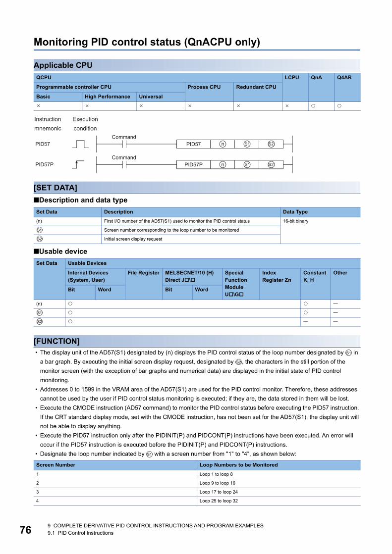
76
Monitoring PID control status (QnACPU only)
Applicable CPU
[SET DATA]
■Description and data type
■Usable device
[FUNCTION] • The display unit of the AD57(S1) designated by (n) displays the PID control status of the loop number designated by in
a bar graph. By executing the initial screen display request, designated by , the characters in the still portion of the
monitor screen (with the exception of bar graphs and numerical data) are displayed in the initial state of PID control
monitoring.
• Addresses 0 to 1599 in the VRAM area of the AD57(S1) are used for the PID control monitor. Therefore, these addresses
cannot be used by the user if PID control status monitoring is executed; if they are, the data stored in them will be lost.
• Execute the CMODE instruction (AD57 command) to monitor the PID control status before executing the PID57 instruction.
If the CRT standard display mode, set with the CMODE instruction, has not been set for the AD57(S1), the display unit will
not be able to display anything.
• Execute the PID57 instruction only after the PIDINIT(P) and PIDCONT(P) instructions have been executed. An error will
occur if the PID57 instruction is executed before the PIDINIT(P) and PIDCONT(P) instructions.
• Designate the loop number indicated by with a screen number from "1" to "4", as shown below:
QCPU LCPU QnA Q4AR
Programmable controller CPU Process CPU Redundant CPU
Basic High Performance Universal
Set Data Description Data Type
(n) First I/O number of the AD57(S1) used to monitor the PID control status 16-bit binary
Screen number corresponding to the loop number to be monitored
Initial screen display request
Set Data Usable Devices
Internal Devices (System, User)
File Register MELSECNET/10 (H) Direct J\
Special Function Module U\G
Index Register Zn
Constant K, H
Other
Bit Word Bit Word
(n)
Screen Number Loop Numbers to be Monitored
1 Loop 1 to loop 8
2 Loop 9 to loop 16
3 Loop 17 to loop 24
4 Loop 25 to loop 32
S1
S2
S1
S2
S1
S2
S1
9 COMPLETE DERIVATIVE PID CONTROL INSTRUCTIONS AND PROGRAM EXAMPLES9.1 PID Control Instructions
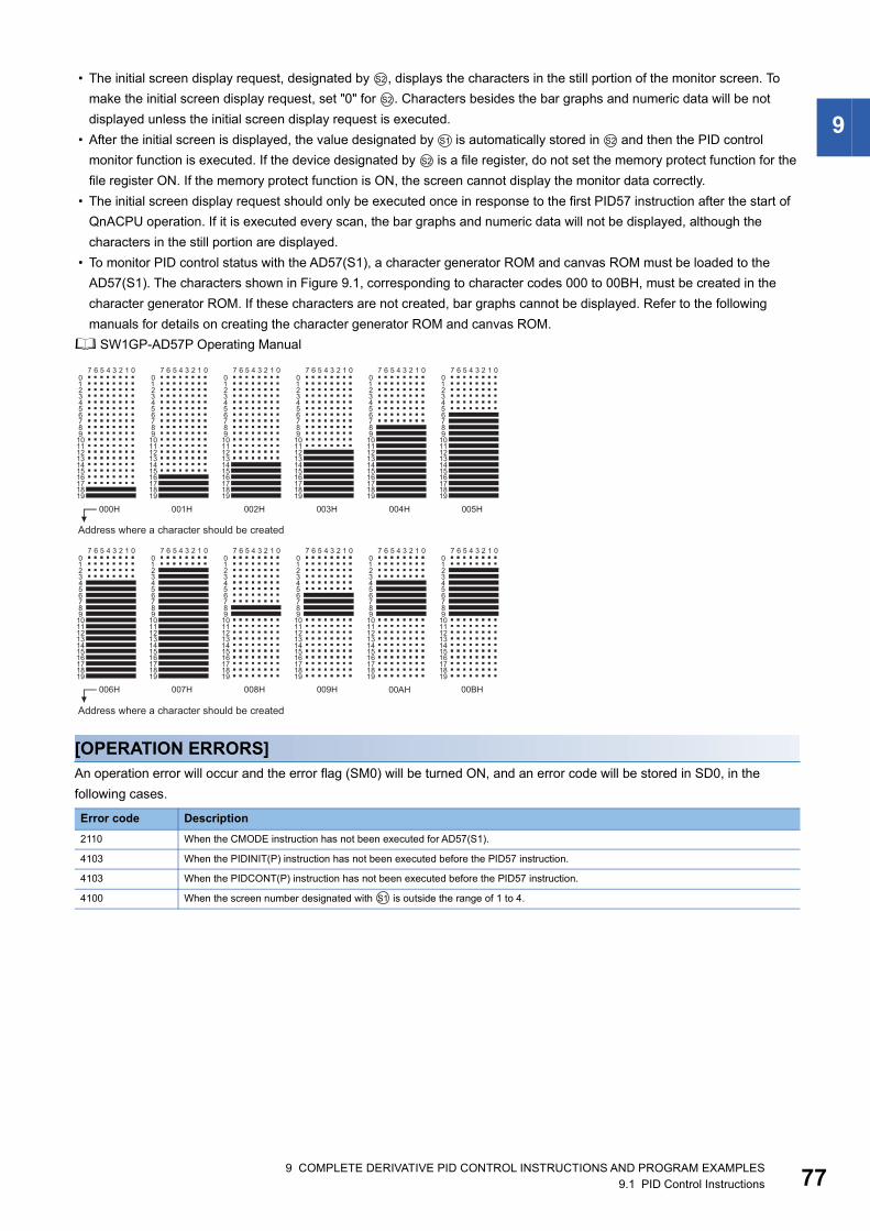
9
• The initial screen display request, designated by , displays the characters in the still portion of the monitor screen. To
make the initial screen display request, set "0" for . Characters besides the bar graphs and numeric data will be not
displayed unless the initial screen display request is executed.
• After the initial screen is displayed, the value designated by is automatically stored in and then the PID control
monitor function is executed. If the device designated by is a file register, do not set the memory protect function for the
file register ON. If the memory protect function is ON, the screen cannot display the monitor data correctly.
• The initial screen display request should only be executed once in response to the first PID57 instruction after the start of
QnACPU operation. If it is executed every scan, the bar graphs and numeric data will not be displayed, although the
characters in the still portion are displayed.
• To monitor PID control status with the AD57(S1), a character generator ROM and canvas ROM must be loaded to the
AD57(S1). The characters shown in Figure 9.1, corresponding to character codes 000 to 00BH, must be created in the
character generator ROM. If these characters are not created, bar graphs cannot be displayed. Refer to the following
manuals for details on creating the character generator ROM and canvas ROM.
SW1GP-AD57P Operating Manual
[OPERATION ERRORS]An operation error will occur and the error flag (SM0) will be turned ON, and an error code will be stored in SD0, in the
following cases.
Error code Description
2110 When the CMODE instruction has not been executed for AD57(S1).
4103 When the PIDINIT(P) instruction has not been executed before the PID57 instruction.
4103 When the PIDCONT(P) instruction has not been executed before the PID57 instruction.
4100 When the screen number designated with is outside the range of 1 to 4.
S2
S2
S1 S2
S2
S1
9 COMPLETE DERIVATIVE PID CONTROL INSTRUCTIONS AND PROGRAM EXAMPLES9.1 PID Control Instructions 77
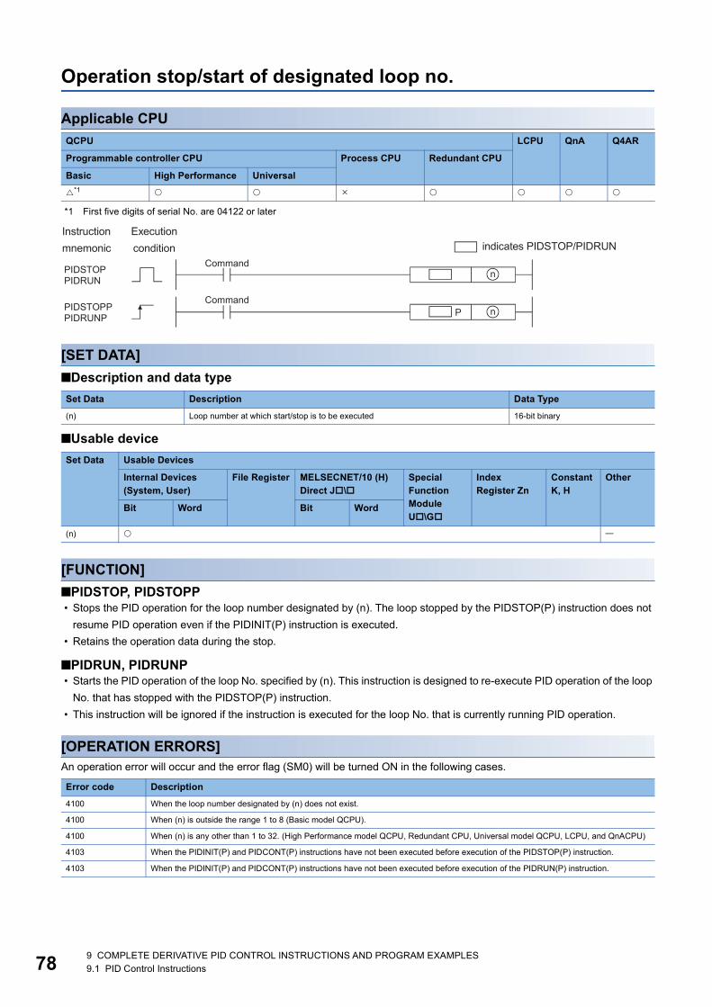
78
Operation stop/start of designated loop no.
Applicable CPU
*1 First five digits of serial No. are 04122 or later
[SET DATA]
■Description and data type
■Usable device
[FUNCTION]
■PIDSTOP, PIDSTOPP • Stops the PID operation for the loop number designated by (n). The loop stopped by the PIDSTOP(P) instruction does not
resume PID operation even if the PIDINIT(P) instruction is executed.
• Retains the operation data during the stop.
■PIDRUN, PIDRUNP • Starts the PID operation of the loop No. specified by (n). This instruction is designed to re-execute PID operation of the loop
No. that has stopped with the PIDSTOP(P) instruction.
• This instruction will be ignored if the instruction is executed for the loop No. that is currently running PID operation.
[OPERATION ERRORS]An operation error will occur and the error flag (SM0) will be turned ON in the following cases.
QCPU LCPU QnA Q4AR
Programmable controller CPU Process CPU Redundant CPU
Basic High Performance Universal
*1
Set Data Description Data Type
(n) Loop number at which start/stop is to be executed 16-bit binary
Set Data Usable Devices
Internal Devices (System, User)
File Register MELSECNET/10 (H) Direct J\
Special Function Module U\G
Index Register Zn
Constant K, H
Other
Bit Word Bit Word
(n)
Error code Description
4100 When the loop number designated by (n) does not exist.
4100 When (n) is outside the range 1 to 8 (Basic model QCPU).
4100 When (n) is any other than 1 to 32. (High Performance model QCPU, Redundant CPU, Universal model QCPU, LCPU, and QnACPU)
4103 When the PIDINIT(P) and PIDCONT(P) instructions have not been executed before execution of the PIDSTOP(P) instruction.
4103 When the PIDINIT(P) and PIDCONT(P) instructions have not been executed before execution of the PIDRUN(P) instruction.
9 COMPLETE DERIVATIVE PID CONTROL INSTRUCTIONS AND PROGRAM EXAMPLES9.1 PID Control Instructions
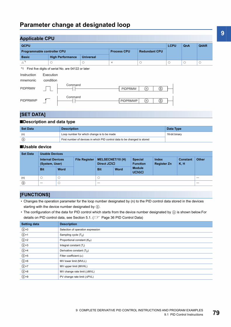
9
Parameter change at designated loopApplicable CPU
*1 First five digits of serial No. are 04122 or later
[SET DATA]
■Description and data type
■Usable device
[FUNCTIONS] • Changes the operation parameter for the loop number designated by (n) to the PID control data stored in the devices
starting with the device number designated by .
• The configuration of the data for PID control which starts from the device number designated by is shown below.For
details on PID control data, see Section 5.1. ( Page 36 PID Control Data)
QCPU LCPU QnA Q4AR
Programmable controller CPU Process CPU Redundant CPU
Basic High Performance Universal
*1
Set Data Description Data Type
(n) Loop number for which change is to be made 16-bit binary
First number of devices in which PID control data to be changed is stored
Set Data Usable Devices
Internal Devices (System, User)
File Register MELSECNET/10 (H) Direct J\
Special Function Module U\G
Index Register Zn
Constant K, H
Other
Bit Word Bit Word
(n)
Setting data Description
+0 Selection of operation expression
+1 Sampling cycle (TS)
+2 Proportional constant (KP)
+3 Integral constant (TI)
+4 Derivative constant (TD)
+5 Filter coefficient ()
+6 MV lower limit (MVLL)
+7 MV upper limit (MVHL)
+8 MV change rate limit (MVL)
+9 PV change rate limit (PVL)
S
S
S
S
S
S
S
S
S
S
S
S
S
S
9 COMPLETE DERIVATIVE PID CONTROL INSTRUCTIONS AND PROGRAM EXAMPLES9.1 PID Control Instructions 79
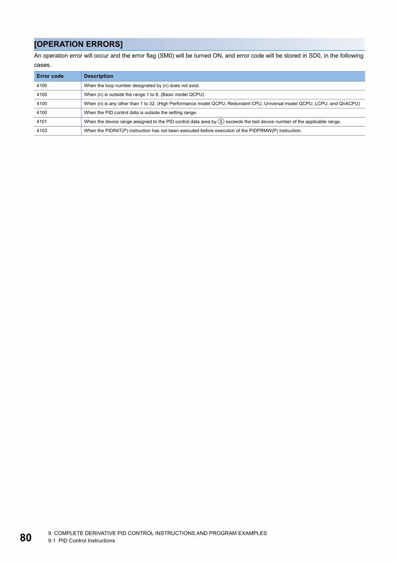
80
[OPERATION ERRORS]An operation error will occur and the error flag (SM0) will be turned ON, and error code will be stored in SD0, in the following
cases.
Error code Description
4100 When the loop number designated by (n) does not exist.
4100 When (n) is outside the range 1 to 8. (Basic model QCPU)
4100 When (n) is any other than 1 to 32. (High Performance model QCPU, Redundant CPU, Universal model QCPU, LCPU, and QnACPU)
4100 When the PID control data is outside the setting range.
4101 When the device range assigned to the PID control data area by exceeds the last device number of the applicable range.
4103 When the PIDINIT(P) instruction has not been executed before execution of the PIDPRMW(P) instruction.
S
9 COMPLETE DERIVATIVE PID CONTROL INSTRUCTIONS AND PROGRAM EXAMPLES9.1 PID Control Instructions

9
9.2 PID Control Program Examples (for QCPU andLCPU)This section describes examples of sequence programs that execute PID control.
System configuration for program examplesThe following illustrates the system configuration for the program examples.
Program example for automatic mode PID controlThis section gives a program example in which PID operation is performed using the digital values imported from the Q64AD
as PV and the MV obtained as a result of PID operation are output from the Q62DA to control external devices.
[PROGRAMMING CONDITIONS] • PID operation is executed for 2 loops.
• The sampling cycle is 1 second.
• The PID control data is set in the following devices: ( Page 36 PID Control Data)
• The I/O data is set in the following devices: ( Page 51 I/O Data)
• The following SV are set for loop 1 and loop 2 using a sequence program:
• The following devices are used for PID control start/stop commands.
• The digital values of the Q64AD and Q62DA are set within the range 0 to 2000.
Module I/O number
Q64AD X/Y80 to X/Y8F
Q62DA X/YA0 to X/YAF
PID control data Device name
Common data D500 to D501
Loop 1 data D502 to D511
Loop 2 data D512 to D521
I/O data Device name
Common data D600 to D609
Loop 1 data D610 to D627
Loop 2 data D628 to D645
Loop SV
Loop 1 600
Loop 2 1000
Command Device name
PID control start command X0
PID control stop command X1
9 COMPLETE DERIVATIVE PID CONTROL INSTRUCTIONS AND PROGRAM EXAMPLES9.2 PID Control Program Examples (for QCPU and LCPU) 81
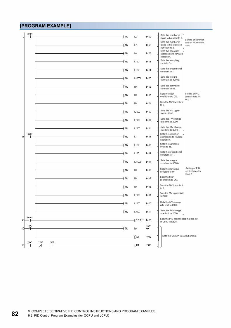
82
[PROGRAM EXAMPLE]
9 COMPLETE DERIVATIVE PID CONTROL INSTRUCTIONS AND PROGRAM EXAMPLES9.2 PID Control Program Examples (for QCPU and LCPU)

9
9 COMPLETE DERIVATIVE PID CONTROL INSTRUCTIONS AND PROGRAM EXAMPLES9.2 PID Control Program Examples (for QCPU and LCPU) 83
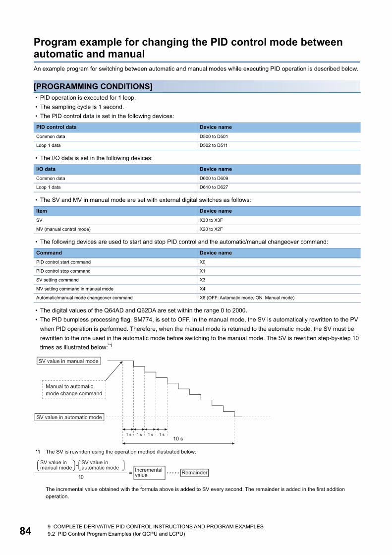
84
Program example for changing the PID control mode between automatic and manualAn example program for switching between automatic and manual modes while executing PID operation is described below.
[PROGRAMMING CONDITIONS] • PID operation is executed for 1 loop.
• The sampling cycle is 1 second.
• The PID control data is set in the following devices:
• The I/O data is set in the following devices:
• The SV and MV in manual mode are set with external digital switches as follows:
• The following devices are used to start and stop PID control and the automatic/manual changeover command:
• The digital values of the Q64AD and Q62DA are set within the range 0 to 2000.
• The PID bumpless processing flag, SM774, is set to OFF. In the manual mode, the SV is automatically rewritten to the PV
when PID operation is performed. Therefore, when the manual mode is returned to the automatic mode, the SV must be
rewritten to the one used in the automatic mode before switching to the manual mode. The SV is rewritten step-by-step 10
times as illustrated below:*1
*1 The SV is rewritten using the operation method illustrated below:
The incremental value obtained with the formula above is added to SV every second. The remainder is added in the first addition operation.
PID control data Device name
Common data D500 to D501
Loop 1 data D502 to D511
I/O data Device name
Common data D600 to D609
Loop 1 data D610 to D627
Item Device name
SV X30 to X3F
MV (manual control mode) X20 to X2F
Command Device name
PID control start command X0
PID control stop command X1
SV setting command X3
MV setting command in manual mode X4
Automatic/manual mode changeover command X6 (OFF: Automatic mode, ON: Manual mode)
9 COMPLETE DERIVATIVE PID CONTROL INSTRUCTIONS AND PROGRAM EXAMPLES9.2 PID Control Program Examples (for QCPU and LCPU)

9
[PROGRAM EXAMPLE]9 COMPLETE DERIVATIVE PID CONTROL INSTRUCTIONS AND PROGRAM EXAMPLES9.2 PID Control Program Examples (for QCPU and LCPU) 85
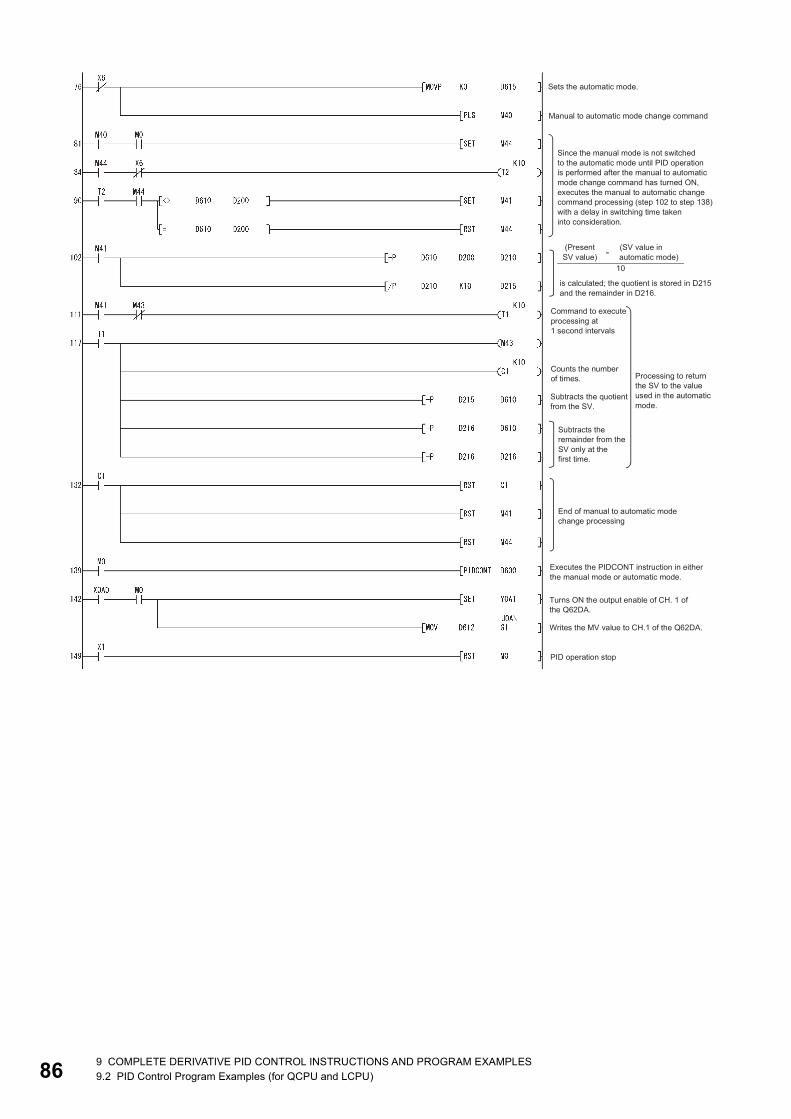
86
9 COMPLETE DERIVATIVE PID CONTROL INSTRUCTIONS AND PROGRAM EXAMPLES9.2 PID Control Program Examples (for QCPU and LCPU)
9
9.3 PID Control Program Examples (QnACPU only)This section describes examples of sequence programs that execute PID control.System configuration for program examplesThe following illustrates the system configuration for the program examples.
Module I/O number
A68AD X/Y80 to X/Y9F
A62DA X/YA0 to X/YBF
AD57 X/YC0 to X/YFF
9 COMPLETE DERIVATIVE PID CONTROL INSTRUCTIONS AND PROGRAM EXAMPLES9.3 PID Control Program Examples (QnACPU only) 87

88
Program example for automatic mode PID controlThis section gives a program example in which PID operation is performed using the digital values imported from the A68AD
as PV and the MV obtained as a result of PID operation are output from the A62DA to control external devices.
[PROGRAMMING CONDITIONS] • PID operation is executed for 2 loops.
• The sampling cycle is 1 second.
• The PID control data is set in the following devices: ( Page 36 PID Control Data)
• The I/O data is set in the following devices: ( Page 51 I/O Data)
• The following SV are set for loop 1 and loop 2 using a sequence program:
• The following devices are used for PID control start/stop commands and the monitoring command with AD57.
• The digital values of the A68AD and A62DA are set within the range 0 to 2000.
PID control data Device name
Common data D500 to D501
Loop 1 data D502 to D511
Loop 2 data D512 to D521
I/O data Device name
Common data D600 to D609
Loop 1 data D610 to D627
Loop 2 data D628 to D645
Loop SV
Loop 1 600
Loop 2 1000
Command Device name
PID control start command X0
PID control stop command X1
Monitoring command with AD57 X2
9 COMPLETE DERIVATIVE PID CONTROL INSTRUCTIONS AND PROGRAM EXAMPLES9.3 PID Control Program Examples (QnACPU only)

9
[PROGRAM EXAMPLE]9 COMPLETE DERIVATIVE PID CONTROL INSTRUCTIONS AND PROGRAM EXAMPLES9.3 PID Control Program Examples (QnACPU only) 89
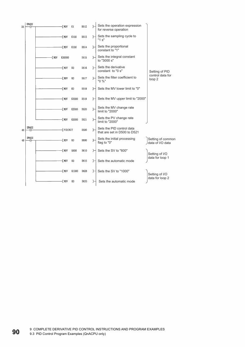
90
9 COMPLETE DERIVATIVE PID CONTROL INSTRUCTIONS AND PROGRAM EXAMPLES9.3 PID Control Program Examples (QnACPU only)
9
*1 It is also possible to create a program by using special function module devices. In this case the format in the ladder is as follows:
*2 It is also possible to create a program by using special function module devices. In this case the format in the ladder is as follows:
*1
*2
9 COMPLETE DERIVATIVE PID CONTROL INSTRUCTIONS AND PROGRAM EXAMPLES9.3 PID Control Program Examples (QnACPU only) 91

92
Program example for changing the PID control mode between automatic and manualAn example program for switching between automatic and manual modes while executing PID operation is described below.
[PROGRAMMING CONDITIONS] • PID operation is executed for 1 loop.
• The sampling cycle is 1 second.
• The PID control data is set in the following devices:
• The I/O data is set in the following devices:
• The SV and MV in manual mode are set with external digital switches as follows:
• The following devices are used to start and stop PID control and the automatic/manual changeover command:
• The digital values of the A68AD and A62DA are set within the range 0 to 2000.
• The PID bumpless processing flag, SM774, is set to OFF. In the manual mode, the SV is automatically rewritten to the PV
when PID operation is performed. Therefore, when the manual mode is returned to the automatic mode, the SV must be
rewritten to the one used in the automatic mode before switching to the manual mode. The SV is rewritten step-by-step 10
times as illustrated below:*1
*1 The SV is rewritten using the operation method illustrated below:
The incremental value obtained with the formula above is added to SV every second. The remainder is added in the first addition operation.
PID control data Device name
Common data D500 to D501
Loop 1 data D502 to D511
I/O data Device name
Common data D600 to D609
Loop 1 data D610 to D627
Item Device name
SV X30 to X3F
MV (manual control mode) X20 to X2F
Command Device name
PID control start command X0
PID control stop command X1
Monitoring command with AD57 X2
SV setting command X3
MV setting command in manual mode X4
Automatic/manual mode changeover command X6 (OFF: Automatic mode, ON: Manual mode)
9 COMPLETE DERIVATIVE PID CONTROL INSTRUCTIONS AND PROGRAM EXAMPLES9.3 PID Control Program Examples (QnACPU only)

9
[PROGRAM EXAMPLE]9 COMPLETE DERIVATIVE PID CONTROL INSTRUCTIONS AND PROGRAM EXAMPLES9.3 PID Control Program Examples (QnACPU only) 93
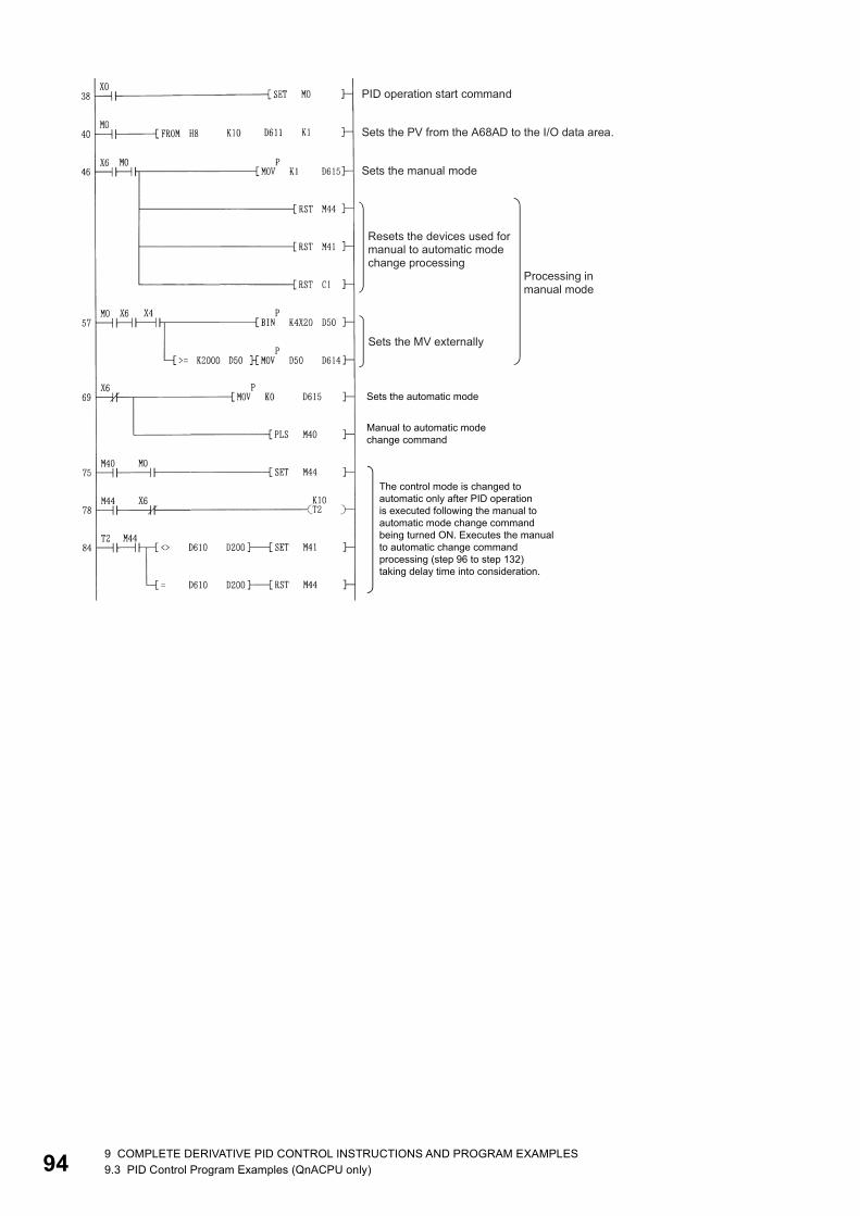
94
9 COMPLETE DERIVATIVE PID CONTROL INSTRUCTIONS AND PROGRAM EXAMPLES9.3 PID Control Program Examples (QnACPU only)
9
9 COMPLETE DERIVATIVE PID CONTROL INSTRUCTIONS AND PROGRAM EXAMPLES9.3 PID Control Program Examples (QnACPU only) 95
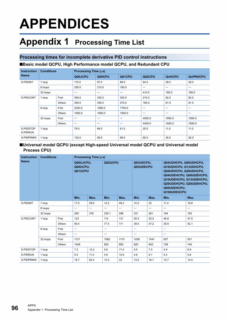
96
APPENDICESAppendix 1 Processing Time List
Processing times for incomplete derivative PID control instructions
■Basic model QCPU, High Performance model QCPU, and Redundant CPU
■Universal model QCPU (except High-speed Universal model QCPU and Universal model Process CPU)
Instruction Name
Conditions Processing Time (s)
Q00JCPU Q00CPU Q01CPU Q02CPU QnHCPU QnPRHCPU
S.PIDINIT 1 loop 115.0 97.0 88.5 64.5 28.0 28.0
8 loops 250.0 210.0 190.0
32 loops 410.0 180.0 180.0
S.PIDCONT 1 loop First 395.0 335.0 300.0 215.0 92.0 92.0
Others 350.0 300.0 270.0 190.0 81.5 81.5
8 loop First 2250.0 1850.0 1700.0
Others 1950.0 1650.0 1500.0
32 loops First 4550.0 1950.0 1950.0
Others 4450.0 1850.0 1850.0
S.PIDSTOP
S.PIDRUN
1 loop 79.5 66.0 61.0 25.0 11.0 11.0
S.PIDPRMW 1 loop 120.0 99.5 89.5 60.0 26.0 26.0
Instruction Name
Conditions Processing Time (s)
Q00UJCPU, Q00UCPU,Q01UCPU
Q02UCPU Q03UDCPU, Q03UDECPU
Q04UDHCPU, Q06UDHCPU,Q10UDHCPU, Q13UDHCPU,Q20UDHCPU, Q26UDHCPU,Q04UDEHCPU, Q06UDEHCPU,Q10UDEHCPU, Q13UDEHCPU,Q20UDEHCPU, Q26UDEHCPU,Q50UDEHCPU, Q100UDEHCPU
Min. Max. Min. Max. Min. Max. Min. Max.
S.PIDINIT 1 loop 17.5 39.9 14.2 48.2 14.2 22 11.4 18.8
8 loops
32 loops 295 376 230.1 298 231 261 164 183
S.PIDCONT 1 loop First 123 114 131 50.5 52.5 46.8 47.5
Others 90.4 77.4 111 39.5 47.2 35.8 42.1
8 loop First
Others
32 loops First 1121 1082 1115 1036 1041 927 931
Others 1046 852 883 820 842 728 744
S.PIDSTOP 1 loop 7.3 14.2 5.6 17.4 5.5 7.5 4.9 6.9
S.PIDRUN 1 loop 5.5 11.0 4.9 10.6 4.8 6.1 4.3 5.6
S.PIDPRMW 1 loop 18.7 62.4 13.3 33 13.0 16.7 10.7 14.5
APPXAppendix 1 Processing Time List
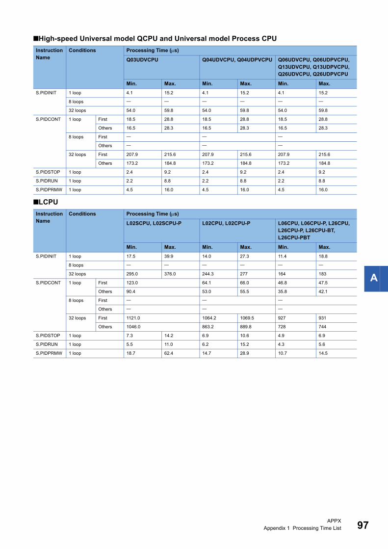
A
■High-speed Universal model QCPU and Universal model Process CPU
■LCPU
Instruction Name
Conditions Processing Time (s)
Q03UDVCPU Q04UDVCPU, Q04UDPVCPU Q06UDVCPU, Q06UDPVCPU, Q13UDVCPU, Q13UDPVCPU, Q26UDVCPU, Q26UDPVCPU
Min. Max. Min. Max. Min. Max.
S.PIDINIT 1 loop 4.1 15.2 4.1 15.2 4.1 15.2
8 loops
32 loops 54.0 59.8 54.0 59.8 54.0 59.8
S.PIDCONT 1 loop First 18.5 28.8 18.5 28.8 18.5 28.8
Others 16.5 28.3 16.5 28.3 16.5 28.3
8 loops First
Others
32 loops First 207.9 215.6 207.9 215.6 207.9 215.6
Others 173.2 184.8 173.2 184.8 173.2 184.8
S.PIDSTOP 1 loop 2.4 9.2 2.4 9.2 2.4 9.2
S.PIDRUN 1 loop 2.2 8.8 2.2 8.8 2.2 8.8
S.PIDPRMW 1 loop 4.5 16.0 4.5 16.0 4.5 16.0
Instruction Name
Conditions Processing Time (s)
L02SCPU, L02SCPU-P L02CPU, L02CPU-P L06CPU, L06CPU-P, L26CPU,L26CPU-P, L26CPU-BT,L26CPU-PBT
Min. Max. Min. Max. Min. Max.
S.PIDINIT 1 loop 17.5 39.9 14.0 27.3 11.4 18.8
8 loops
32 loops 295.0 376.0 244.3 277 164 183
S.PIDCONT 1 loop First 123.0 64.1 66.0 46.8 47.5
Others 90.4 53.0 55.5 35.8 42.1
8 loops First
Others
32 loops First 1121.0 1064.2 1069.5 927 931
Others 1046.0 863.2 889.8 728 744
S.PIDSTOP 1 loop 7.3 14.2 6.9 10.6 4.9 6.9
S.PIDRUN 1 loop 5.5 11.0 6.2 15.2 4.3 5.6
S.PIDPRMW 1 loop 18.7 62.4 14.7 28.9 10.7 14.5
APPXAppendix 1 Processing Time List 97

98
Processing times for complete derivative PID control instructions
■Basic model QCPU, High Performance model QCPU, and Redundant CPU
■Universal model QCPU (except High-speed Universal model QCPU and Universal model Process CPU)
Instruction Name
Conditions Processing Time (s)
Q2ASCPU, Q2ACPU(S1)
Q3ACPU Q2ASHCPU(S1), Q4ACPU, A4ARCPU
Q00JCPU
Q00CPU Q01CPU Q02CPU QnHCPU QnPRHCPU
PIDINIT 1 loop 61 46 23 66.0 56.0 50.5 26.0 11.2 11.2
8 loops 170.0 145.0 130.0
32 loops 407 306 153 174.0 74.9 74.9
PIDCONT 1 loop First 211 159 80 325.0 275.0 245.0 86.6 37.3 37.3
Others 181 136 68 285.0 250.0 225.0 74.3 32.0 32.0
8 loops First 2000.0 1700.0 1500.0
Others 1700.0 1450.0 1300.0
32 loops First 5086 3824 1912 2102.5 904.9 904.9
Others 4894 3680 1840 2036.9 876.7 876.7
PID57 1 loop First 9629 7240 3620
Others 606 456 228
8 loops First 9669 7270 3635
Others 3719 2796 1398
PIDSTOP
PIDRUN
1 loop 11.2 8.4 4.2 22.0 18.5 17.0 4.5 1.9 1.9
PIDPRMW 1 loop 36 26 13 53.0 45.0 41.0 14.6 6.3 6.3
Instruction Name
Conditions Processing Time (s)
Q00UJCPU,Q00UCPU,Q01UCPU
Q02UCPU Q03UDCPU,Q03UDECPU
Q04UDHCPU, Q06UDHCPU,Q10UDHCPU, Q13UDHCPU,Q20UDHCPU, Q26UDHCPU,Q04UDEHCPU, Q06UDEHCPU,Q10UDEHCPU, Q13UDEHCPU,Q20UDEHCPU, Q26UDEHCPU,Q50UDEHCPU, Q100UDEHCPU
Min. Max. Min. Max. Min. Max. Min. Max.
PIDINIT 1 loop 10.3 60.7 8.2 27.7 8.2 12.4 6.3 10.9
8 loops
32 loops 162 227 129 159 129 133 98.7 122.6
PIDCONT 1 loop First 111 101 102 40.6 41.5 36.8
Others 95.5 51.5 74.4 33.6 38.5 35.8
8 loop First
Others
32 loops First 909 931 939 862 872 776 785
Others 914 764 788 736 757 622 645
PIDSTOP 1 loop 3.3 33.4 1.8 6.7 1.8 3.4 1.3 2.9
PIDRUN 1 loop 1 4 1.7 6.7 1.7 3.2 1.5 2.7
PIDPRMW 1 loop 9.4 23 6.9 17.6 6.9 10.3 5.9 8.9
APPXAppendix 1 Processing Time List

A
■High-speed Universal model QCPU and Universal model Process CPU
■LCPU
Instruction Name
Conditions Processing Time (s)
Q03UDVCPU Q04UDVCPU, Q04UDPVCPU Q06UDVCPU, Q06UDPVCPU, Q13UDVCPU, Q13UDPVCPU, Q26UDVCPU, Q26UDPVCPU
Min. Max. Min. Max. Min. Max.
PIDINIT 1 loop 2.7 9.3 2.7 9.3 2.7 9.3
8 loops
32 loops 35.6 39.9 35.6 39.9 35.6 39.9
PIDCONT 1 loop First 14.3 22.7 14.3 22.7 14.3 22.7
Others 11.9 21.3 11.9 21.3 11.9 21.3
8 loops First
Others
32 loops First 196.0 199.5 196.0 199.5 196.0 199.5
Others 160.8 167.5 160.8 167.5 160.8 167.5
PIDSTOP 1 loop 1.3 2.9 1.3 2.9 1.3 2.9
PIDRUN 1 loop 1.3 3.0 1.3 3.0 1.3 3.0
PIDPRMW 1 loop 2.8 3.7 2.8 3.7 2.8 3.7
Instruction Name
Conditions Processing Time (s)
L02SCPU, L02SCPU-P L02CPU, L02CPU-P L06CPU, L06CPU-P,L26CPU, L26CPU-P,L26CPU-BT, L26CPU-PBT
Min. Max. Min. Max. Min. Max.
PIDINIT 1 loop 10.3 60.7 8.6 14.6 6.3 10.9
8 loops
32 loops 162.0 227.0 131.2 136.7 98.7 122.6
PIDCONT 1 loop First 110.0 51.5 51.8 36.8
Others 95.5 50.0 50.4 35.8
8 loops First
Others
32 loops First 909.0 869.5 886.9 776.0 785.0
Others 914.0 746.2 750.3 622.0 645.0
PIDSTOP 1 loop 3.3 33.4 2.2 4.0 1.3 2.9
PIDRUN 1 loop 1.0 4.0 2.2 4.2 1.5 2.7
PIDPRMW 1 loop 9.4 23.0 8.0 12.0 5.9 8.9
APPXAppendix 1 Processing Time List 99
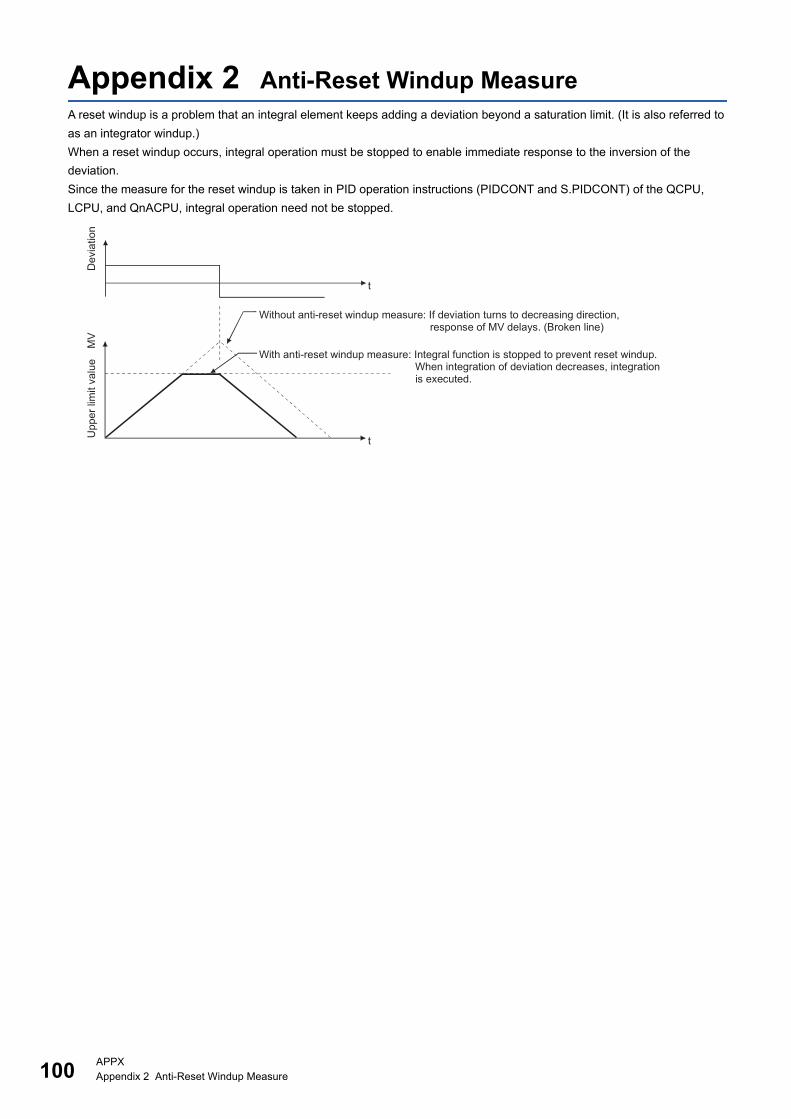
100APPXAppendix 2 Anti-Reset Windup Measure
Appendix 2 Anti-Reset Windup MeasureA reset windup is a problem that an integral element keeps adding a deviation beyond a saturation limit. (It is also referred to
as an integrator windup.)
When a reset windup occurs, integral operation must be stopped to enable immediate response to the inversion of the
deviation.
Since the measure for the reset windup is taken in PID operation instructions (PIDCONT and S.PIDCONT) of the QCPU,
LCPU, and QnACPU, integral operation need not be stopped.
101
I
INDEX
A
About the differences between complete derivative and incomplete derivative . . . . . . . . . . . . . . . . . 30Anti-reset windup measure. . . . . . . . . . . . . . . . 100Applicable CPU . . . . . . . . . . . . . . . . . . . . . . . . 13
B
Bumpless changeover function. . . . . . . . . . . . . . 31
D
Derivative operation (D operation). . . . . . . . . . . . 29
F
Forward operation. . . . . . . . . . . . . . . . . . . . . . . 26
I
I/O Data . . . . . . . . . . . . . . . . . . . . . . . . . . . . . . 51I/O data allocations . . . . . . . . . . . . . . . . . . . . . . 53Integral operation (I operation) . . . . . . . . . . . . . . 28
M
MV upper/lower limit control function . . . . . . . . . . 31
O
Operation method . . . . . . . . . . . . . . . . . . . . . . . 26Operation when PID operation instruction executed . . . . . . . . . . . . . . . . . . . . . . . . . . . . . 11Outline of PID control . . . . . . . . . . . . . . . . . . . . 25Overview of PID control processing. . . . . . . . . . . 11
P
PID control data allocations . . . . . . . . . . . . . . . . 47PID control instruction list. . . . . . . . . . . . . . . . 16,21PID control procedure . . . . . . . . . . . . . . . . . . . . 34PID operation . . . . . . . . . . . . . . . . . . . . . . . . . . 30PID operation block diagram and operation expressions . . . . . . . . . . . . . . . . . . . . . . . . . 15,20Process value derivative type operation. . . . . . . . 26Processing time list . . . . . . . . . . . . . . . . . . . . . . 96Proportional operation (P operation) . . . . . . . . . . 27
R
Reverse operation. . . . . . . . . . . . . . . . . . . . . . . 26
S
Sampling cycle . . . . . . . . . . . . . . . . . . . . . . . . . 50Settings of SV, PV, and MV used in the PID control instructions . . . . . . . . . . . . . . . . . . . . . . 12
V
Velocity type operation . . . . . . . . . . . . . . . . . . . .26

102
MEMO
103
I
INSTRUCTION INDEX
P
PID57 . . . . . . . . . . . . . . . . . . . . . . . . . . . . . . . 76PID57P . . . . . . . . . . . . . . . . . . . . . . . . . . . . . . 76PIDCONT. . . . . . . . . . . . . . . . . . . . . . . . . . . . . 74PIDCONTP . . . . . . . . . . . . . . . . . . . . . . . . . . . 74PIDINIT . . . . . . . . . . . . . . . . . . . . . . . . . . . . . . 72PIDINITP . . . . . . . . . . . . . . . . . . . . . . . . . . . . . 72PIDPRMW . . . . . . . . . . . . . . . . . . . . . . . . . . . . 79PIDPRMWP . . . . . . . . . . . . . . . . . . . . . . . . . . . 79PIDRUN. . . . . . . . . . . . . . . . . . . . . . . . . . . . . . 78PIDRUNP. . . . . . . . . . . . . . . . . . . . . . . . . . . . . 78PIDSTOP. . . . . . . . . . . . . . . . . . . . . . . . . . . . . 78PIDSTOPP. . . . . . . . . . . . . . . . . . . . . . . . . . . . 78
S
S.PIDCONT . . . . . . . . . . . . . . . . . . . . . . . . . . . 61S.PIDINIT. . . . . . . . . . . . . . . . . . . . . . . . . . . . . 60S.PIDPRMW . . . . . . . . . . . . . . . . . . . . . . . . . . 64S.PIDRUN . . . . . . . . . . . . . . . . . . . . . . . . . . . . 63S.PIDSTOP . . . . . . . . . . . . . . . . . . . . . . . . . . . 63SP.PIDCONT . . . . . . . . . . . . . . . . . . . . . . . . . . 61SP.PIDINIT . . . . . . . . . . . . . . . . . . . . . . . . . . . 60SP.PIDPRMW . . . . . . . . . . . . . . . . . . . . . . . . . 64SP.PIDRUN . . . . . . . . . . . . . . . . . . . . . . . . . . . 63SP.PIDSTOP . . . . . . . . . . . . . . . . . . . . . . . . . . 63

104
MEMO
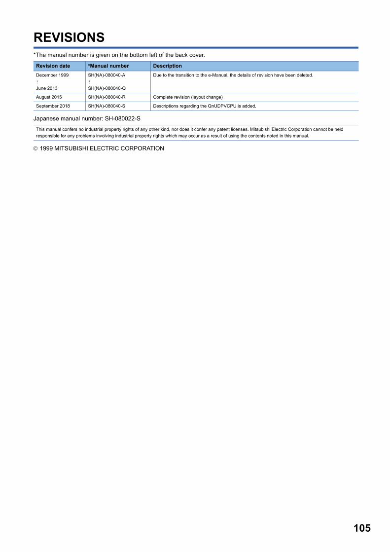
105
REVISIONS*The manual number is given on the bottom left of the back cover.
Japanese manual number: SH-080022-S
1999 MITSUBISHI ELECTRIC CORPORATION
Revision date *Manual number Description
December 1999
June 2013
SH(NA)-080040-A
SH(NA)-080040-Q
Due to the transition to the e-Manual, the details of revision have been deleted.
August 2015 SH(NA)-080040-R Complete revision (layout change)
September 2018 SH(NA)-080040-S Descriptions regarding the QnUDPVCPU is added.
This manual confers no industrial property rights of any other kind, nor does it confer any patent licenses. Mitsubishi Electric Corporation cannot be held
responsible for any problems involving industrial property rights which may occur as a result of using the contents noted in this manual.

106
WARRANTYPlease confirm the following product warranty details before using this product.
1. Gratis Warranty Term and Gratis Warranty RangeIf any faults or defects (hereinafter "Failure") found to be the responsibility of Mitsubishi occurs during use of the product within the gratis warranty term, the product shall be repaired at no cost via the sales representative or Mitsubishi Service Company.However, if repairs are required onsite at domestic or overseas location, expenses to send an engineer will be solely at the customer's discretion. Mitsubishi shall not be held responsible for any re-commissioning, maintenance, or testing on-site that involves replacement of the failed module.[Gratis Warranty Term]The gratis warranty term of the product shall be for one year after the date of purchase or delivery to a designated place.Note that after manufacture and shipment from Mitsubishi, the maximum distribution period shall be six (6) months, and the longest gratis warranty term after manufacturing shall be eighteen (18) months. The gratis warranty term of repair parts shall not exceed the gratis warranty term before repairs.[Gratis Warranty Range](1) The range shall be limited to normal use within the usage state, usage methods and usage environment, etc., which
follow the conditions and precautions, etc., given in the instruction manual, user's manual and caution labels on the product.
(2) Even within the gratis warranty term, repairs shall be charged for in the following cases.1. Failure occurring from inappropriate storage or handling, carelessness or negligence by the user. Failure caused
by the user's hardware or software design.2. Failure caused by unapproved modifications, etc., to the product by the user.3. When the Mitsubishi product is assembled into a user's device, Failure that could have been avoided if functions
or structures, judged as necessary in the legal safety measures the user's device is subject to or as necessary by industry standards, had been provided.
4. Failure that could have been avoided if consumable parts (battery, backlight, fuse, etc.) designated in the instruction manual had been correctly serviced or replaced.
5. Failure caused by external irresistible forces such as fires or abnormal voltages, and Failure caused by force majeure such as earthquakes, lightning, wind and water damage.
6. Failure caused by reasons unpredictable by scientific technology standards at time of shipment from Mitsubishi.7. Any other failure found not to be the responsibility of Mitsubishi or that admitted not to be so by the user.
2. Onerous repair term after discontinuation of production(1) Mitsubishi shall accept onerous product repairs for seven (7) years after production of the product is discontinued.
Discontinuation of production shall be notified with Mitsubishi Technical Bulletins, etc.(2) Product supply (including repair parts) is not available after production is discontinued.
3. Overseas serviceOverseas, repairs shall be accepted by Mitsubishi's local overseas FA Center. Note that the repair conditions at each FA Center may differ.
4. Exclusion of loss in opportunity and secondary loss from warranty liabilityRegardless of the gratis warranty term, Mitsubishi shall not be liable for compensation of damages caused by any cause found not to be the responsibility of Mitsubishi, loss in opportunity, lost profits incurred to the user by Failures of Mitsubishi products, special damages and secondary damages whether foreseeable or not, compensation for accidents, and compensation for damages to products other than Mitsubishi products, replacement by the user, maintenance of on-site equipment, start-up test run and other tasks.
5. Changes in product specificationsThe specifications given in the catalogs, manuals or technical documents are subject to change without prior notice.
SH(NA)-080040-S


SH(NA)-080040-S(1809)MEE
MODEL: QCPU(Q)-P(PI)-E
MODEL CODE: 13JF59
Specifications subject to change without notice.
When exported from Japan, this manual does not require application to theMinistry of Economy, Trade and Industry for service transaction permission.
HEAD OFFICE : TOKYO BUILDING, 2-7-3 MARUNOUCHI, CHIYODA-KU, TOKYO 100-8310, JAPANNAGOYA WORKS : 1-14 , YADA-MINAMI 5-CHOME , HIGASHI-KU, NAGOYA , JAPAN