madison beltline precast concrete pavement … · concrete pavement technology, is available at ....
TRANSCRIPT

FHWA REPORT NO. FHWA-HIF-17-003
FHWA PROJECT R05 IAP FUNDED PROJECT CASE STUDY
MADISON BELTLINE PRECAST
CONCRETE PAVEMENT
DEMONSTRATION PROJECT
October 2016

Notice
This document is disseminated under the sponsorship of the U.S. Department of Transportation
in the interest of information exchange. The U.S. Government assumes no liability for the use of
the information contained in this document.
The U.S. Government does not endorse products or manufacturers. Trademarks or
manufacturers' names appear in this report only because they are considered essential to the
objective of the document.
Quality Assurance Statement
The Federal Highway Administration (FHWA) provides high-quality information to serve
Government, industry, and the public in a manner that promotes public understanding. Standards
and policies are used to ensure and maximize the quality, objectivity, utility, and integrity of its
information. FHWA periodically reviews quality issues and adjusts its programs and processes to
ensure continuous quality improvement.

1. Report No.
FHWA-HIF-17-003
2. Government Accession No
3. Recipient’s Catalog No
3. Title and Subtitle
FHWA Project R05 IAP Funded Project Case Study: Madison Beltline
Precast Concrete Pavement Demonstration Project
5. Report Date
October 2016
6. Performing Organization Code
7. Authors
Shiraz Tayabji, Ph.D., P.E.
8. Performing Organization Report No.
9. Performing Organization Name and Address
Applied Research Associates, Inc.
100 Trade Centre Drive, Suite 200
Champaign, IL 61820
10. Work Unit No. (TRAIS) C6B
11. Contract or Grant No.
DTFH61-13-C-00028
12. Sponsoring Agency Name and Address
Office of Infrastructure
Federal Highway Administration
1200 New Jersey Avenue, SE
Washington, DC 20590
13. Type of Report and Period Covered
Final Report
April 2014 – September 2014
14. Sponsoring Agency Code
Project No. 1983
15. Supplementary Notes
Contracting Officer’s Representative: Sam Tyson, P.E.
16. Abstract
The production use of precast concrete pavement (PCP) has come a long way over the last 15 years. The technology is
gaining wider acceptance in the U.S. for rapid repair and rehabilitation of concrete pavements as well as for heavily
trafficked asphalt concrete pavements and intersections. Several U.S. highway agencies have implemented the PCP
technology, and other agencies have constructed demonstration projects.
In the U.S., the PCP technology is being used for intermittent repairs (full-depth joint repairs or full panel
replacement) and for continuous applications (longer length/wider area rehabilitation) with service life expectations of
at least 20 years for intermittent repairs and at least 40 years for continuous applications, without significant future
corrective treatment.
The Strategic Highway Research Program 2 (SHRP2) Project R05 was conducted from 2008 to 2012 to develop
technical information and guidelines that would encourage the rapid and successful adoption of PCP technology. In
2013, the SHRP2 Implementation Assistance Program (IAP) was created to help State highway agencies, metropolitan
planning organizations, and other interested organizations deploy SHRP2-developed products order to deliver more
efficient, cost-effective solutions to meet complex challenges. On March 28, 2014, as part of round 3 of the IAP, four
lead adopters were selected to receive financial support from the Federal Highway Administration for implementation
of PCP technology. Wisconsin Department of Transportation, one of the agencies selected as a lead adopter, received
an award of $300,000 to help offset the cost of the implementation of PCP technology in the State.
This case study report provides details of the 2014 PCP use for repair of distressed concrete pavement along sections
of the Madison Beltline Highway (MBH/US 12).
17. Key Words
Precast concrete pavement system, construction,
pavement rehabilitation, SHRP2, SHRP2 Project
R05
18. Distribution Statement
No restriction.
Security Classification (of this
report)
Unclassified
19. Security Classification (of this
page): Unclassified
20. No. of Pages
29
21. Price
Form DOT F 1700.7 (8-72) Reproduction of completed page authorized

ii
TABLE OF CONTENTS
INTRODUCTION ........................................................................................................................ 1
SHRP2 PROJECT R05 BACKGROUND .......................................................................................................... 1
SHRP2 PROJECT R05 PRODUCT IMPLEMENTATION PROGRAM ...................................................... 2
PROJECT DETAILS ................................................................................................................... 3
PROJECT DESCRIPTION ................................................................................................................................. 3
PAVEMENT DETAILS ....................................................................................................................................... 4
PRECAST CONCRETE PAVEMENT SYSTEM USED ................................................................................. 5
CONSTRUCTION STAGING AND TRAFFIC-RELATED REQUIREMENTS .......................................... 9
PANEL FABRICATION ................................................................................................................................... 12
PANEL INSTALLATION ................................................................................................................................. 13
LESSONS LEARNED........................................................................................................................................ 19
SUMMARY ......................................................................................................................................................... 20
ACKNOWLEDGMENTS .......................................................................................................... 23

iii
TABLE OF FIGURES
Figure 1. Map. Location of the project. .......................................................................................... 3 Figure 2. Photo. View of the project. .............................................................................................. 4 Figure 3. Photo. Super Slab panel form setup. ............................................................................... 6 Figure 4. Photo. Super Slab panel form stripping. .......................................................................... 6 Figure 5. Photo. Dowel bar slots and foam gaskets at the panel bottom. ....................................... 7 Figure 6. Photo. Bottom slot filled with grout. ............................................................................... 8 Figure 7. Photo. Super Slab system panel installation. ................................................................... 9 Figure 8. Illustration. Stage 1 lane closure and traffic flow.......................................................... 10 Figure 9. Photo. Stage 1 lane closure and traffic flow. ................................................................. 10 Figure 10. Illustration. Stage 2 lane closure and traffic flow. ....................................................... 10
Figure 11. Photo. Stage 2 lane closure and traffic flow after completed repairs in Lane 1 and
Lane 2............................................................................................................................................ 11 Figure 12. Illustration. Stage 3 outside shoulder and Lane 3 closure and traffic flow. ................ 11 Figure 13. Photo. Stage 3 outside shoulder closure and traffic flow after completed repairs in
Lane 2 and Lane 3. ........................................................................................................................ 11 Figure 14. Photo. Panel setup. ...................................................................................................... 13 Figure 15. Chart. Nightly schedule for panel installation. ............................................................ 14 Figure 16. Photo. Distressed slab removal process....................................................................... 15 Figure 17. Photo. Dowel bars installed in the repair area. ............................................................ 15 Figure 18. Photo. Fine-grading of the bedding layer. ................................................................... 16 Figure 19. Photo. Panels on a delivery truck. ............................................................................... 16 Figure 20. Photo. Panel trimming operation. ................................................................................ 17 Figure 21. Photo. A typical panel placement. ............................................................................... 17
Figure 22. Photo. Grout application into the bottom dowel slots. ................................................ 18 Figure 23. Photo. Grout application along a longitudinal joint. ................................................... 18 Figure 24. Photo. Traffic over the repaired Lane 2. ...................................................................... 18
TABLE OF TABLES
Table 1. Bedding material gradation. .............................................................................................. 7 Table 2. Lane rental charges. ........................................................................................................ 12 Table 3. Panel geometry tolerances. ............................................................................................. 13

iv
MODERN METRIC CONVERSION FACTORS
Conversion factors both to and from the modern metric International System of Units (SI) can be
found at: http://www.fhwa.dot.gov/publications/convtabl.cfm.

v
ABBREVIATIONS AND ACRONYMS
AADT Annual average daily traffic
AASHTO American Association of State Highway and Transportation Officials
AC Asphalt concrete
DOT Department of transportation
FHWA Federal Highway Administration
FMC Fort Miller Company, Inc.
IAP Implementation Assistance Program
MBH Madison Beltline Highway
PCP Precast concrete pavement
SHRP2 Strategic Highway Research Program 2

vi
1
INTRODUCTION
The production use of precast concrete pavement (PCP) has come a long way over the last 15
years. The technology is gaining wider acceptance in the U.S. for rapid repair and rehabilitation
of concrete pavements as well as for heavily trafficked asphalt concrete pavements and
intersections. Several U.S. highway agencies—including Caltrans, Illinois Tollway, and the New
Jersey, New York, and Utah State Departments of Transportation (DOTs)—have implemented
the PCP technology, and other agencies have constructed demonstration projects. There have
also been many advances in the design, panel fabrication, and panel installation aspects of the
PCP technology.
In the U.S., the PCP technology is being used for intermittent repairs (full-depth joint repairs or
full panel replacement) and for continuous applications (longer length/wider area rehabilitation)
with service life expectations of at least 20 years for intermittent repairs and at least 40 years for
continuous applications, without significant future corrective treatment.
PCP technology can significantly reduce traffic impacts of roadway repair and reconstruction
projects, particularly on heavily traveled routes. The technology is applicable to small segments,
enabling flexibility in construction phasing, as well as for use in corridor-wide pavement
reconstruction.
SHRP2 PROJECT R05 BACKGROUND
Because the information on PCP technology was not well documented, in 2007 the Strategic
Highway Research Program 2 (SHRP2) initiated Project R05 to develop the necessary technical
information and guidelines that would encourage the rapid and successful adoption of this new
technology. The Project R05 study was conducted from 2008 to 2012. The final report, Precast
Concrete Pavement Technology, is available at http://www.trb.org/main/blurbs/167788.aspx.
The study demonstrated that the PCP technology is ready for wider implementation and that
many of the PCP systems available in the U.S. can meet the needs of highway agencies for rapid
renewal of their highway systems. The following products were developed under SHRP2 Project
R05:
Overall findings related to viability of the PCP technology.
Findings based on SHRP2 field testing.
Guidelines for PCP project selection.
Guidelines for PCP system acceptance.
Guidelines for design of PCP systems.
Guidelines for PCP fabrication.
Guidelines for PCP installation.
Implementation plan for PCP technology.
Long-term monitoring plan for PCP projects.
Model specifications.

2
The review of projects constructed in the U.S. and the SHRP2 field testing indicated that
sufficient advances have been made to reliably design and construct PCP systems to achieve five
key attributes of successful pavements, as follows:
Constructability—Techniques and equipment are available to ensure acceptable
production rates for the installation of PCP systems.
Concrete durability—Plant fabrication of precast panels results in excellent concrete
strength and durability.
Load transfer at joints—Reliable and economical techniques are available to provide
effective load transfer at transverse joints in jointed PCP systems and post-tensioned PCP
systems.
Panel support—Techniques to provide adequate and uniform base support conditions
continue to be improved.
Efficiency—Panels are thinner than standard cast-in-place concrete and last longer
because of prestressing and/or reinforcing elements in the PCP system.
SHRP2 PROJECT R05 PRODUCT IMPLEMENTATION PROGRAM
In 2013, the Federal Highway Administration (FHWA) and the American Association of State
Highway and Transportation Officials (AASHTO) created the SHRP2 Implementation
Assistance Program (IAP) to help State DOTs, metropolitan planning organizations, and other
interested organizations deploy SHRP2-developed products to deliver more efficient, cost-
effective solutions to meet complex challenges. Seven rounds of the IAP were offered between
February 2013 and April 2016.
On March 28, 2014, as part of round 3 of the IAP, four lead adopters were selected to receive
financial support from the FHWA for implementation of PCP technology. Wisconsin DOT, one
of the agencies selected as a lead adopter, received an award of $300,000 to help offset the cost
of the implementation of PCP technology in the State. The objective of the award was to allow
Wisconsin DOT to construct a demonstration project that would provide a learning environment
for operations such as fabricating panels, setting panels, installing dowel bars, grouting under
panel areas, and other related activities needed to implement precast panel installations in
Wisconsin. It should be noted that Wisconsin DOT had constructed a small PCP demonstration
project during 2013. At the time of the IAP award, Wisconsin DOT was planning to rehabilitate
deteriorated concrete pavement sections of the Madison Beltline Highway. The IAP funding
helped offset a portion of the funds for the pavement rehabilitation using PCP for a production
project.
This case study report provides details of the PCP implementation on a concrete pavement
rehabilitation project along sections of the Madison Beltline Highway (MBH/US 12). The
project was constructed between April and September 2014.

3
PROJECT DETAILS
PROJECT DESCRIPTION
A 7-mile section of MBH/US 12 was selected for repair during 2014. Both the eastbound and
the westbound lanes of the highway carry a high volume of commuter and truck traffic. As of
2014, the annual average daily traffic (AADT) along the project site was about 120,000
vehicles/day. As shown in figure 1, the highway is adjacent to several lakes, and there is a lack
of alternate routes within the project location, increasing the importance of this highway.
Therefore, any extended lane closures for any pavement repair work needed to be kept to a
minimum. Any extended or daytime lane closures along any sections of the MBH/US 12
typically result in significant backups during the morning and afternoon rush hours.
In the past, the full-depth repairs and single or multiple full-panel repairs were carried out using
rapid setting cast-in-place concrete. However, because of the need for longer-lasting treatments,
Wisconsin DOT considered implementing the PCP technology for this repair project, utilizing
the SHRP2 IAP funding to offset the cost of using PCP for the repair work.
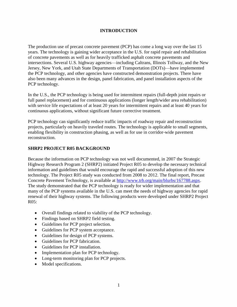
The existing concrete pavement at the project site was exhibiting severe distress in both the
eastbound and westbound lanes. The concrete pavement distress typically consisted of corner
cracking and joint spalling. Figure 2 shows a view of the distress along the 7-mile section of the
highway prior to installation of the PCP.
Figure 1. Map. Location of the project.
4
Figure 2. Photo. View of the project.
The PCP project was awarded to Zignego Company, Inc. The project work consisted of
fabricating, furnishing, and installing precast concrete panels in accordance with the project
plans and specification. The work included performing a field survey, removing the existing
concrete pavement, grading and compacting the existing aggregate base, grading and compacting
the bedding material layer, installing dowel bars, placing panels, installing dowel grout in bottom
slots and along joint gaps, installing undersealing grout under the panels, and performing
diamond grinding. The repair locations were identified in the plans, and additional repair
locations were determined at the site by the Engineer of Record.
The project details included the following:
Project No.: 1206-04-62.
Project owner: Wisconsin DOT.
Prime contractor: Zignego Company, Inc, Waukesha, Wisconsin.
PCP system vendor: Fort Miller Company, Inc. (FMC), Schuylerville, New York.
Panel precaster: Wieser Concrete, Portage, Wisconsin.
Project plans and specification: Wisconsin DOT and HNTB, Madison, Wisconsin.
Construction management support: AECOM Transportation, Middleton, Wisconsin.
Dowel slot grout: SpecChem (Repcon 928); later switched to Dayton Superior (HD 50) at
request of Wisconsin DOT.
Panel undersealing grout: Grout mix design provided by FMC consisting of Type I or III
portland cement, water, and approved viscosity reducing admixture. Project utilized
MasterRoc FLC 100 admixture (formerly MEYCO Flowcable) by BASF Corporation.
PAVEMENT DETAILS
The original pavement, across the three lanes plus an auxiliary lane in each direction, is a 10-
inch-thick jointed concrete pavement that was constructed between 1987 and 1989. The
transverse joint spacing is repeated random at 13, 19, 18, and 12 feet, and the joints are skewed.
The details of the rehabilitation are as follows:

5
Section length to be repaired: intermittent repairs over a length of 7 miles.
Number of lanes rehabilitated: all three in each direction.
Total number of panels installed: 623, in the middle lane.
PCP system: FMC’s Super Slab® system.
Panel dimensions: 12 feet wide and variable length (6, 8, 10 feet) by 10 inches thick.
Repair area length: 6 feet (single panel) to 192 feet (multiple panels).
Joint load transfer: 14-inch-long dowel bars spaced at 15 inches (two clusters of four);
dowel diameter of 1.5 inches.
Tie-bar use: none.
Existing base (left in place): granular base.
Bedding layer: crusher run aggregate (stone dust) or manufactured aggregate sand
allowed.
Dowel bar and tie-bar slot grout: capable of being pumped into the slots; a minimum
compressive strength of 2,500 psi before the panels are open to traffic and a minimum
compressive strength of 5,000 psi at 28 days.
Panel undersealing grout: to meet the required maximum flow rate of 20 seconds (as per
ASTM C939) and a compressive strength of 600 psi in 12 hours.
PRECAST CONCRETE PAVEMENT SYSTEM USED
The Super Slab system used for this project is a proprietary system developed in 2001. Since
2001, several highway agencies have used the Super Slab system for intermittent concrete
pavement repairs and for rehabilitation of concrete and asphalt pavements. The Super Slab
system consists of the following components.
Reinforced Precast Panels
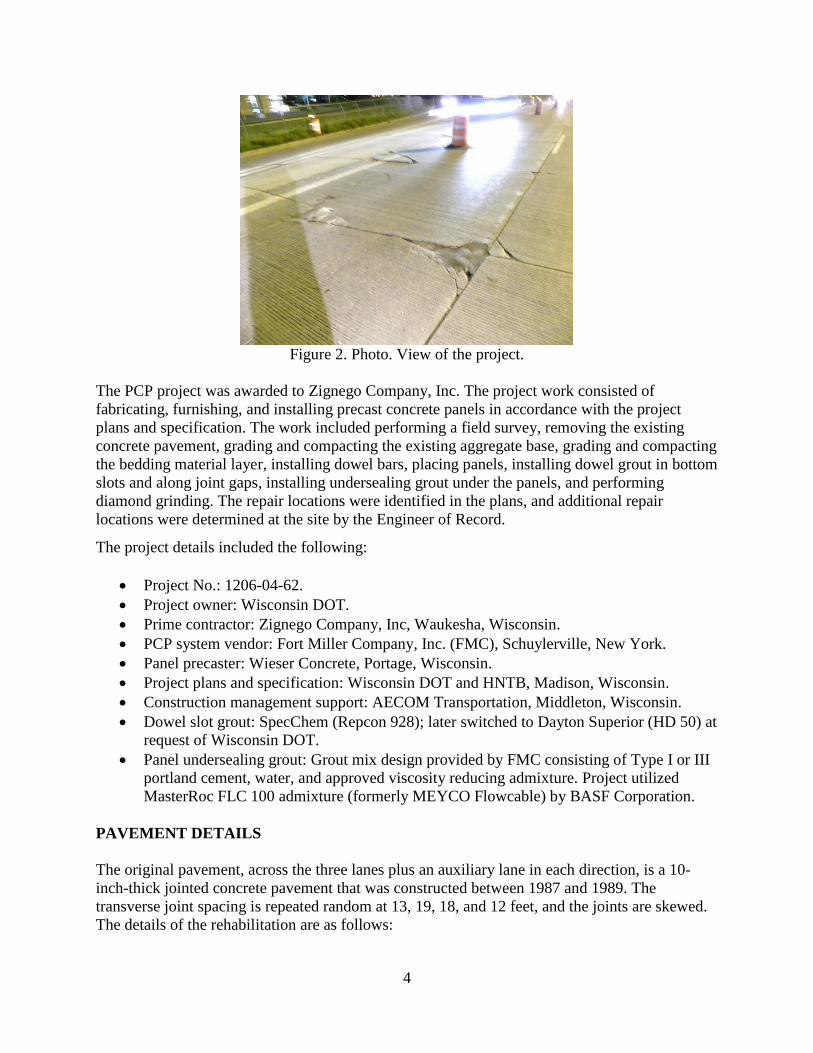
The panels are fabricated in an approved precast concrete plant, always using steel forms. When
the panels are produced by another FMC-approved precaster, FMC typically leases a set of
forms to the precaster and provides training in form setup, casting, finishing, foam gasket
installation, storage, and shipment to the job site. A typical form setup for a Super Slab panel is
shown in figure 3. Figure 4 shows the stripping of the forms at about 16 hours after concrete
placement.
6
Figure 3. Photo. Super Slab panel form setup.
Figure 4. Photo. Super Slab panel form stripping.
The Super Slab panels incorporate the following features:
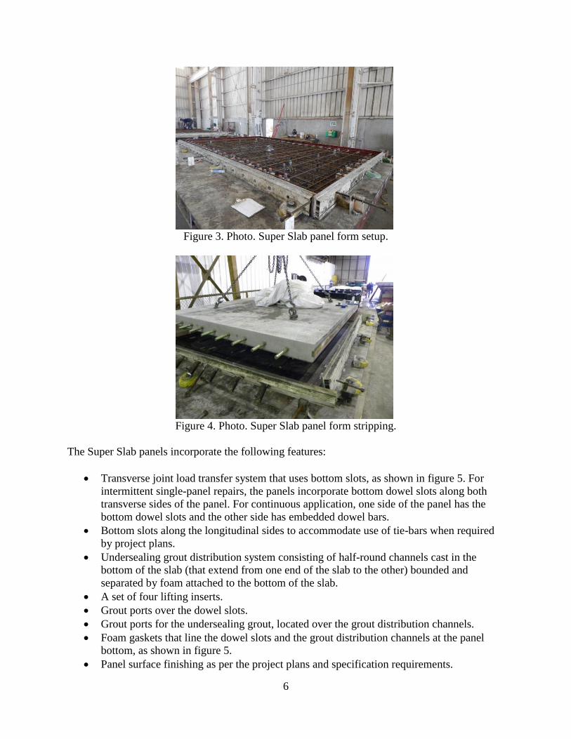
Transverse joint load transfer system that uses bottom slots, as shown in figure 5. For
intermittent single-panel repairs, the panels incorporate bottom dowel slots along both
transverse sides of the panel. For continuous application, one side of the panel has the
bottom dowel slots and the other side has embedded dowel bars.
Bottom slots along the longitudinal sides to accommodate use of tie-bars when required
by project plans.
Undersealing grout distribution system consisting of half-round channels cast in the
bottom of the slab (that extend from one end of the slab to the other) bounded and
separated by foam attached to the bottom of the slab.
A set of four lifting inserts.
Grout ports over the dowel slots.
Grout ports for the undersealing grout, located over the grout distribution channels.
Foam gaskets that line the dowel slots and the grout distribution channels at the panel
bottom, as shown in figure 5.
Panel surface finishing as per the project plans and specification requirements.
7
Figure 5. Photo. Dowel bar slots and foam gaskets at the panel bottom.
Bedding Layer
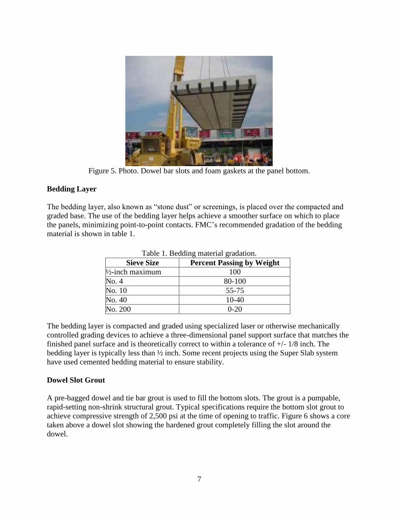
The bedding layer, also known as “stone dust” or screenings, is placed over the compacted and
graded base. The use of the bedding layer helps achieve a smoother surface on which to place
the panels, minimizing point-to-point contacts. FMC’s recommended gradation of the bedding
material is shown in table 1.
Table 1. Bedding material gradation.
Sieve Size Percent Passing by Weight
½-inch maximum 100
No. 4 80-100
No. 10 55-75
No. 40 10-40
No. 200 0-20
The bedding layer is compacted and graded using specialized laser or otherwise mechanically
controlled grading devices to achieve a three-dimensional panel support surface that matches the
finished panel surface and is theoretically correct to within a tolerance of +/- 1/8 inch. The
bedding layer is typically less than ½ inch. Some recent projects using the Super Slab system
have used cemented bedding material to ensure stability.
Dowel Slot Grout
A pre-bagged dowel and tie bar grout is used to fill the bottom slots. The grout is a pumpable,
rapid-setting non-shrink structural grout. Typical specifications require the bottom slot grout to
achieve compressive strength of 2,500 psi at the time of opening to traffic. Figure 6 shows a core
taken above a dowel slot showing the hardened grout completely filling the slot around the
dowel.

8
Figure 6. Photo. Bottom slot filled with grout.
Undersealing Grout
A non-structural bedding grout is used for undersealing below the panel to ensure full contact of
the panel bottom with the base. The grout is pumped through the grout ports at one end of each
grout channel until it exudes from a grout port at the other end of the same channel.
Installation
The Super Slab system can be used to produce non-planar (warped) panels using a patented
process. The use of the Super Slab system requires the repaired/rehabilitated roadway to be
ground to ensure a smoother pavement surface. The following are the Super Slab system
installation steps:
1. Mark repair limits (engineer) and measure existing lane width (contractor).
2. Remove existing pavement.
3. Drill and epoxy-grout dowel bars in the existing pavement joint faces.
a. For repair application, do this along both sides of the existing pavement
b. For continuous application, do this along the approach and leave sides of the
pavement rehabilitation area.
4. Prepare existing base or new base (grade and compact).
5. Place bedding layer. Grade and compact the bedding layer.
6. Set panels over the prepared bedding layer, with the bottom slots located over the dowel
bars in the existing pavement or in the adjacent panels.
7. For continuous application, maintain the transverse joint widths as small as possible.
8. Open to traffic
9. During a later lane closure:
a. Fill the bottom dowel bar slots using the dowel slot grout.
b. Apply the panel undersealing grout.
c. Complete finishing activities.
d. Open to traffic.
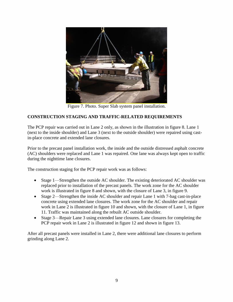
The Super Slab system panel installation is shown in figure 7.
9
Figure 7. Photo. Super Slab system panel installation.
CONSTRUCTION STAGING AND TRAFFIC-RELATED REQUIREMENTS
The PCP repair was carried out in Lane 2 only, as shown in the illustration in figure 8. Lane 1
(next to the inside shoulder) and Lane 3 (next to the outside shoulder) were repaired using cast-
in-place concrete and extended lane closures.
Prior to the precast panel installation work, the inside and the outside distressed asphalt concrete
(AC) shoulders were replaced and Lane 1 was repaired. One lane was always kept open to traffic
during the nighttime lane closures.
The construction staging for the PCP repair work was as follows:
Stage 1—Strengthen the outside AC shoulder. The existing deteriorated AC shoulder was
replaced prior to installation of the precast panels. The work zone for the AC shoulder
work is illustrated in figure 8 and shown, with the closure of Lane 3, in figure 9.
Stage 2—Strengthen the inside AC shoulder and repair Lane 1 with 7-bag cast-in-place
concrete using extended lane closures. The work zone for the AC shoulder and repair
work in Lane 2 is illustrated in figure 10 and shown, with the closure of Lane 1, in figure
11. Traffic was maintained along the rebuilt AC outside shoulder.
Stage 3—Repair Lane 3 using extended lane closures. Lane closures for completing the
PCP repair work in Lane 2 is illustrated in figure 12 and shown in figure 13.
After all precast panels were installed in Lane 2, there were additional lane closures to perform
grinding along Lane 2.

10
Figure 8. Illustration. Stage 1 lane closure and traffic flow.
Figure 9. Photo. Stage 1 lane closure and traffic flow.
Figure 10. Illustration. Stage 2 lane closure and traffic flow.
11
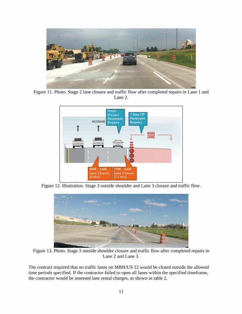
Figure 11. Photo. Stage 2 lane closure and traffic flow after completed repairs in Lane 1 and
Lane 2.
Figure 12. Illustration. Stage 3 outside shoulder and Lane 3 closure and traffic flow.
Figure 13. Photo. Stage 3 outside shoulder closure and traffic flow after completed repairs in
Lane 2 and Lane 3.
The contract required that no traffic lanes on MBH/US 12 would be closed outside the allowed
time periods specified. If the contractor failed to open all lanes within the specified timeframe,
the contractor would be assessed lane rental charges, as shown in table 2.

12
Table 2. Lane rental charges.
Time Period in Excess of Specified
Time
15 Minute Lane Rental
Charge (per lane)
Cumulative Lane Rental
Charge (per lane)
1st 15 minutes $750 $750
2nd 15 minutes $1,500 $2,250
3rd 15 minutes $2,250 $4,500
4th 15 minutes & beyond $3,000 $7,500 & up
Before the field installation work started, Wisconsin DOT conducted extensive public awareness
activities, including posting the project description and regular updates at the DOT’s website.
PANEL FABRICATION
Panels were fabricated by Wieser Concrete, a precaster on Wisconsin DOT’s Approved Precast
Concrete Fabricators list. The panels were shipped to the project site from the precast plant in
Portage, Wisconsin, a distance of about 45 miles. The panels were fabricated based on shop
drawings prepared by FMC and approved by Wisconsin DOT. A summary of the panel
fabrication requirements is given below:
1. Design the concrete mixture for the panels in accordance with Materials Procedure MP
711.03.23 Mix Design for Portland Cement Concrete to conform to Section 501 or
Section 601 Class H. Do not disturb or remove the precast panels from the fabrication
forms until a minimum compressive strength of 2,500 psi is achieved. Furnish a precast
concrete panel design which provides for a 28-day strength of 5,000 psi or higher.
2. Provide panels with a smooth bottom surface.
3. Provide panels with an accurately screeded top surface. The top surface texturing of the
precast panel shall match the existing texture of abutting pavement.
4. Cast epoxy-coated dowel bars in the panel at transverse joint ends as shown on the plans
and Super-Slab fabricator standard drawings. Apply form oil or other bond-breaker
material to the dowel bars prior to placing concrete in the form.
5. Cast bottom slots to accommodate dowel bars as detailed on the plans.
6. Design lifting devices to lift the panels from the topside. Recess each lifting device in the
panel a minimum of 1 in. below the surface.
7. Provide each panel with a 1-inch-thick by 1-inch-wide wide foam gasket consisting of
open cell two-pound polyester material attached to the underside edge of the panel to
prevent undersealing grout and dowel slot grout leakage and to create confined grout
chambers between corresponding grout ports.
8. Produce panels to tolerances given in table 3.
9. Include lifting and storage details on the shop drawings for all precast panels. Do not
remove formwork or lift panels until the concrete reaches strength of at least 2,500 psi
unless otherwise indicated on the plans.
10. Store panels on wood dunnage with support points indicated on the shop drawings.
11. Ship panels on wood dunnage. Do not transport or erect panels until they reach the
required 28-day compressive strength of 5,000 psi.
13
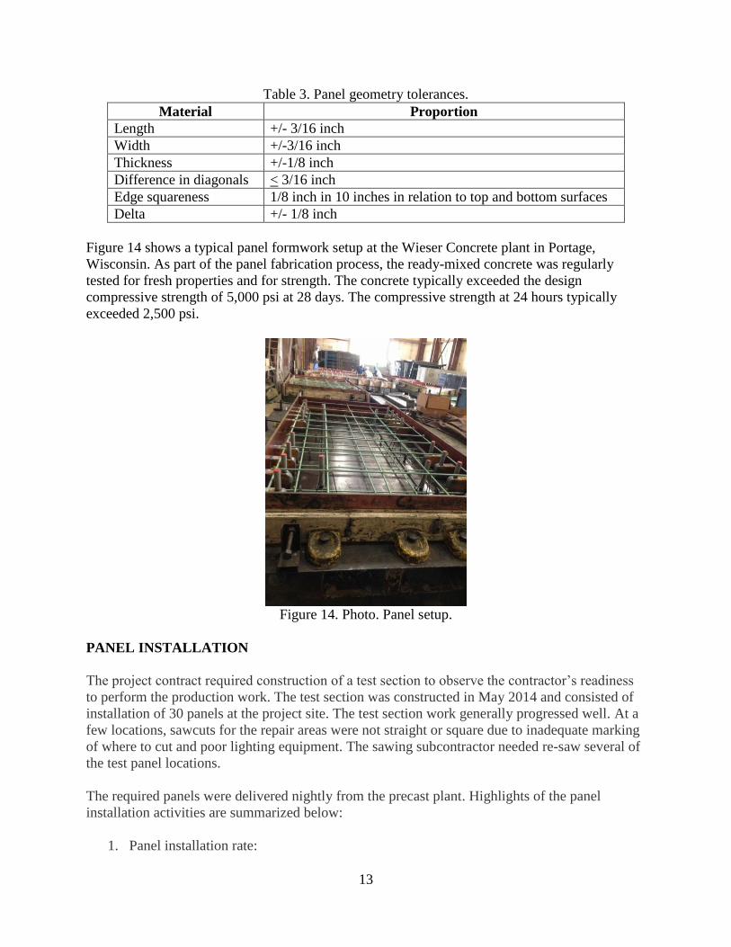
Table 3. Panel geometry tolerances.
Material Proportion
Length +/- 3/16 inch
Width +/-3/16 inch
Thickness +/-1/8 inch
Difference in diagonals < 3/16 inch
Edge squareness 1/8 inch in 10 inches in relation to top and bottom surfaces
Delta +/- 1/8 inch
Figure 14 shows a typical panel formwork setup at the Wieser Concrete plant in Portage,
Wisconsin. As part of the panel fabrication process, the ready-mixed concrete was regularly
tested for fresh properties and for strength. The concrete typically exceeded the design
compressive strength of 5,000 psi at 28 days. The compressive strength at 24 hours typically
exceeded 2,500 psi.
Figure 14. Photo. Panel setup.
PANEL INSTALLATION
The project contract required construction of a test section to observe the contractor’s readiness
to perform the production work. The test section was constructed in May 2014 and consisted of
installation of 30 panels at the project site. The test section work generally progressed well. At a
few locations, sawcuts for the repair areas were not straight or square due to inadequate marking
of where to cut and poor lighting equipment. The sawing subcontractor needed re-saw several of
the test panel locations.
The required panels were delivered nightly from the precast plant. Highlights of the panel
installation activities are summarized below:
1. Panel installation rate:
14
a. Average number of panels installed per night: 17.
b. Maximum number of panels installed: 28; there was higher production when
multiple panels were installed at any location. There were many nights of 20 to 22
panel installations.
2. Longest repair length: 192 ft.
3. Total number of panels installed: 623.
4. Although construction traffic was not allowed on the repair panels right after grouting,
construction traffic occasionally drove over freshly grouted panels because traffic cones
were not positioned at the repair areas. The specification required construction traffic not
to drive over the grouted panels until the dowel slot grout had reached a minimum
compressive strength of 2,500 psi. However, the construction staff did not monitor the
grout strength.
5. The vertical differential at a transverse joint before setting the next slab was required to
not exceed ¼ inch.
6. A laser device was used to align and sawcut the transverse boundaries of the repair areas
using the longitudinal joint as a reference. However, sometimes this did not provide a
true perpendicular. This resulted in skewed joints when panels were placed in the repair
areas, with the joint gap varying from ½ inch at one end of the panel to almost 2 inches at
the other end of the panel.
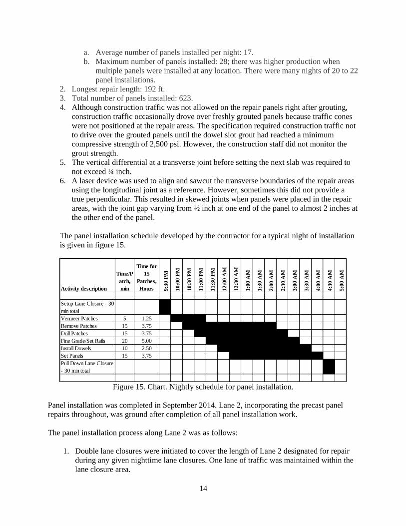
The panel installation schedule developed by the contractor for a typical night of installation
is given in figure 15.
Figure 15. Chart. Nightly schedule for panel installation.
Panel installation was completed in September 2014. Lane 2, incorporating the precast panel
repairs throughout, was ground after completion of all panel installation work.
The panel installation process along Lane 2 was as follows:
1. Double lane closures were initiated to cover the length of Lane 2 designated for repair
during any given nighttime lane closures. One lane of traffic was maintained within the
lane closure area.
Activity description
Time/P
atch,
min
Time for
15
Patches,
Hours 9:3
0 P
M
10:0
0 P
M
10:3
0 P
M
11:0
0 P
M
11:3
0 P
M
12:0
0 A
M
12:3
0 A
M
1:0
0 A
M
1:3
0 A
M
2:0
0 A
M
2:3
0 A
M
3:0
0 A
M
3:3
0 A
M
4:0
0 A
M
4:3
0 A
M
5:0
0 A
M
Setup Lane Closure - 30
min total x
Vermeer Patches 5 1.25 x x x
Remove Patches 15 3.75 x x x x x x x x
Drill Patches 15 3.75 x x x x x x x x
Fine Grade/Set Rails 20 5.00 x x x x x x x x
Install Dowels 10 2.50 x x x x x x x x
Set Panels 15 3.75 x x x x x x x x
Pull Down Lane Closure
- 30 min total x

15
2. The existing distressed concrete slabs were removed. The distressed slab removal
involved individual slabs or portions of slabs as well as multiple slabs. The longest
continuous slab removal length was 192 feet. The slab removal process is shown in
figure 16.
3. The base was regraded and compacted.
4. Holes for dowel bars were drilled in the existing pavement and dowel bars were epoxy-
grouted in the holes. Figure 17 shows a repair area with epoxy-grouted dowel bars.
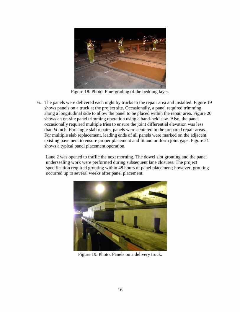
5. The fine-graded bedding layer was applied and using a hand operated screeding device,
as shown in figure 18. The bedding layer grade was checked to ensure it did not vary
from the theoretical elevation by more than +1/8 inch over the length of each panel.
Figure 16. Photo. Distressed slab removal process.
Figure 17. Photo. Dowel bars installed in the repair area.
16
Figure 18. Photo. Fine-grading of the bedding layer.
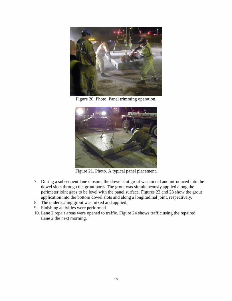
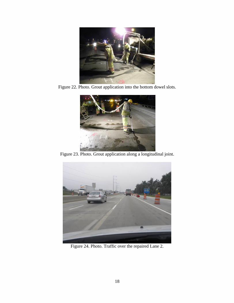
6. The panels were delivered each night by trucks to the repair area and installed. Figure 19
shows panels on a truck at the project site. Occasionally, a panel required trimming
along a longitudinal side to allow the panel to be placed within the repair area. Figure 20
shows an on-site panel trimming operation using a hand-held saw. Also, the panel
occasionally required multiple tries to ensure the joint differential elevation was less
than ¼ inch. For single slab repairs, panels were centered in the prepared repair areas.
For multiple slab replacement, leading ends of all panels were marked on the adjacent
existing pavement to ensure proper placement and fit and uniform joint gaps. Figure 21
shows a typical panel placement operation.
Lane 2 was opened to traffic the next morning. The dowel slot grouting and the panel
undersealing work were performed during subsequent lane closures. The project
specification required grouting within 48 hours of panel placement; however, grouting
occurred up to several weeks after panel placement.
Figure 19. Photo. Panels on a delivery truck.
17
Figure 20. Photo. Panel trimming operation.
Figure 21. Photo. A typical panel placement.
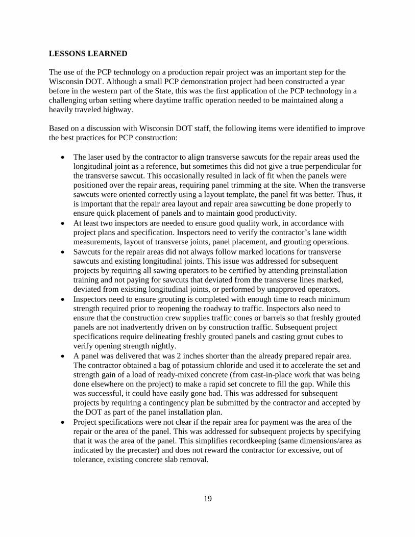
7. During a subsequent lane closure, the dowel slot grout was mixed and introduced into the
dowel slots through the grout ports. The grout was simultaneously applied along the
perimeter joint gaps to be level with the panel surface. Figures 22 and 23 show the grout
application into the bottom dowel slots and along a longitudinal joint, respectively.
8. The undersealing grout was mixed and applied.
9. Finishing activities were performed.
10. Lane 2 repair areas were opened to traffic. Figure 24 shows traffic using the repaired
Lane 2 the next morning.
18
Figure 22. Photo. Grout application into the bottom dowel slots.
Figure 23. Photo. Grout application along a longitudinal joint.
Figure 24. Photo. Traffic over the repaired Lane 2.
19
LESSONS LEARNED
The use of the PCP technology on a production repair project was an important step for the
Wisconsin DOT. Although a small PCP demonstration project had been constructed a year
before in the western part of the State, this was the first application of the PCP technology in a
challenging urban setting where daytime traffic operation needed to be maintained along a
heavily traveled highway.
Based on a discussion with Wisconsin DOT staff, the following items were identified to improve
the best practices for PCP construction:
The laser used by the contractor to align transverse sawcuts for the repair areas used the
longitudinal joint as a reference, but sometimes this did not give a true perpendicular for
the transverse sawcut. This occasionally resulted in lack of fit when the panels were
positioned over the repair areas, requiring panel trimming at the site. When the transverse
sawcuts were oriented correctly using a layout template, the panel fit was better. Thus, it
is important that the repair area layout and repair area sawcutting be done properly to
ensure quick placement of panels and to maintain good productivity.
At least two inspectors are needed to ensure good quality work, in accordance with
project plans and specification. Inspectors need to verify the contractor’s lane width
measurements, layout of transverse joints, panel placement, and grouting operations.
Sawcuts for the repair areas did not always follow marked locations for transverse
sawcuts and existing longitudinal joints. This issue was addressed for subsequent
projects by requiring all sawing operators to be certified by attending preinstallation
training and not paying for sawcuts that deviated from the transverse lines marked,
deviated from existing longitudinal joints, or performed by unapproved operators.
Inspectors need to ensure grouting is completed with enough time to reach minimum
strength required prior to reopening the roadway to traffic. Inspectors also need to
ensure that the construction crew supplies traffic cones or barrels so that freshly grouted
panels are not inadvertently driven on by construction traffic. Subsequent project
specifications require delineating freshly grouted panels and casting grout cubes to
verify opening strength nightly.
A panel was delivered that was 2 inches shorter than the already prepared repair area.
The contractor obtained a bag of potassium chloride and used it to accelerate the set and
strength gain of a load of ready-mixed concrete (from cast-in-place work that was being
done elsewhere on the project) to make a rapid set concrete to fill the gap. While this
was successful, it could have easily gone bad. This was addressed for subsequent
projects by requiring a contingency plan be submitted by the contractor and accepted by
the DOT as part of the panel installation plan.
Project specifications were not clear if the repair area for payment was the area of the
repair or the area of the panel. This was addressed for subsequent projects by specifying
that it was the area of the panel. This simplifies recordkeeping (same dimensions/area as
indicated by the precaster) and does not reward the contractor for excessive, out of
tolerance, existing concrete slab removal.

20
There was an issue with timely bedding and dowel bar grouting and bedding grout not
being installed the same night as the dowel bar grout. The Super Slab system designer’s
directions were not clear. This item was clarified in subsequent project specifications.
The project allowed a maximum ¾-inch gap between the panel and existing pavement
along the longitudinal joint. The contractor took lane width measurements at each side
of the panel, and the system designer subtracted 1.5 inches from the narrowest
measurement, ensuring that the joint width tolerances would not be met unless the two
end measurements were the same. This issue was addressed with the Super Slab system
designer.
SUMMARY
The Madison Beltline Highway project is considered a successful implementation of the PCP
technology on a production basis by an agency that had only constructed a PCP demonstration
project previously.

21

22

23
ACKNOWLEDGMENTS
The support of the Wisconsin DOT staff, particularly David Layton, P.E., during the data
collection for this report and the construction site visits is gratefully acknowledged.