m-net converter - КиевКлимат · centralized control(m-net) ... sheet-metal component,...
TRANSCRIPT
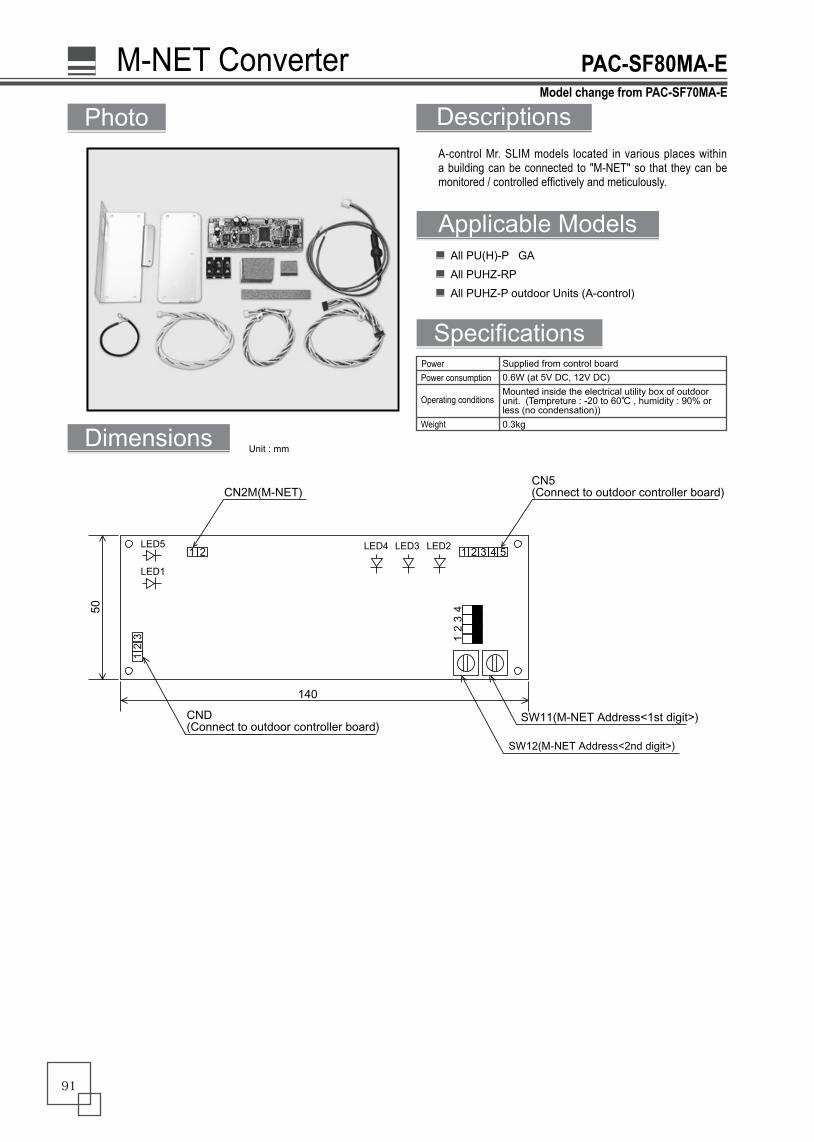
A-control Mr. SLIM models located in various places within a building can be connected to "M-NET" so that they can be monitored / controlled effictively and meticulously.
Photo
Specifications
All PU(H)-P GA
All PUHZ-RP
All PUHZ-P outdoor Units (A-control)
M-NET Converter PAC-SF80MA-E
Descriptions
Applicable Models
Dimensions Unit : mm
����������� �� ������� ���������� ������
� � � � �
����
� �
�����������
���
���������� ����������� �������
���������� ����������� �������
���
��
����������� �� ������� ���������� ������
SW1
����������������
����
Mounted inside the electrical utility box of outdoor unit. (Tempreture : -20 to 60℃ , humidity : 90% or less (no condensation))
Supplied from control boardPower
Operating conditions
Weight 0.3kg
0.6W (at 5V DC, 12V DC)Power consumption
Model change from PAC-SF70MA-E
91
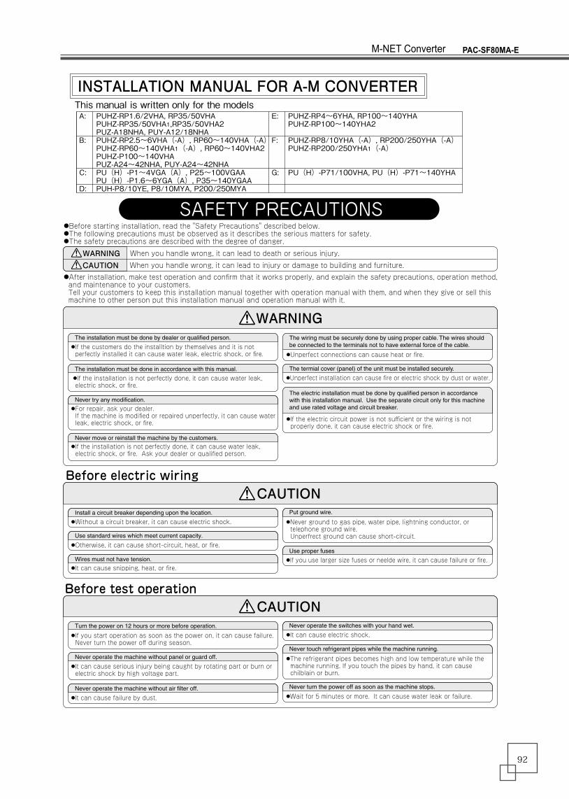
INSTALLATION MANUAL FOR A-M CONVERTERThis manual is written only for the models
SAFETY PRECAUTIONS
●After installation, make test operation and confirm that it works properly, and explain the safety precautions, operation method, and maintenance to your customers. Tell your customers to keep this installation manual together with operation manual with them, and when they give or sell this machine to other person put this installation manual and operation manual with it.
●Before starting installation, read the "Safety Precautions" described below.●The following precautions must be observed as it describes the serious matters for safety.●The safety precautions are described with the degree of danger.
WARNING
WARNING
CAUTIONWhen you handle wrong, it can lead to death or serious injury.
When you handle wrong, it can lead to injury or damage to building and furniture.
������������������������������������������������������������●If the customers do the installtion by themselves and it is not perfectly installed it can cause water leak, electric shock, or fire.
●If the installation is not perfectly done, it can cause water leak, electric shock, or fire.
�������������������������������������������������������������
���������������������������●For repair, ask your dealer. If the machine is modified or repaired unperfectly, it can cause water leak, electric shock, or fire.
�����������������������������������������������������●If the installation is not perfectly done, it can cause water leak, electric shock, or fire. Ask your dealer or qualified person.
Before electric wiringCAUTION
�����������������������������������������������������������������������������������������������������������������������������������������������
●Unperfect connections can cause heat or fire.
�����������������������������������������������������������������
●Unperfect installation can cause fire or electric shock by dust or water.
��������������������������������������������������������������������������������������������������������������������������������������������������������������������������������������������������
●If the electric circuit power is not sufficient or the wiring is not properly done, it can cause electric shock or fire.
●Without a circuit breaker, it can cause electric shock.������������������������������������������������������
�����������������������������������������������
●Otherwise, it can cause short-circuit, heat, or fire.
����������������������������●It can cause snipping, heat, or fire.
����������������
●Never ground to gas pipe, water pipe, lightning conductor, or telephone ground wire. Unperfrect ground can cause short-circuit.
����������������●If you use larger size fuses or neelde wire, it can cause failure or fire.
Before test operation
����������������������������������������������������
●If you start operation as soon as the power on, it can cause failure. Never turn the power off during season.
�����������������������������������������������������
●It can cause serious injury being caught by rotating part or burn or electric shock by high voltage part.
�������������������������������������������������
●It can cause failure by dust.
����������������������������������������������
●It can cause electric shock.
��������������������������������������������������������
●The refrigerant pipes becomes high and low temperature while the machine running. If you touch the pipes by hand, it can cause chilblain or burn.
������������������������������������������������������
●Wait for 5 minutes or more. It can cause water leak or failure.
CAUTION
A:
B:
C:
D:
E:
F:
G:
PUHZ-RP1.6/2VHA, RP35/50VHAPUHZ-RP35/50VHA1,RP35/50VHA2PUZ-A18NHA, PUY-A12/18NHAPUHZ-RP2.5~6VHA(-A), RP60~140VHA(-A)PUHZ-RP60~140VHA1(-A), RP60~140VHA2PUHZ-P100~140VHAPUZ-A24~42NHA, PUY-A24~42NHAPU(H)-P1~4VGA(A), P25~100VGAAPU(H)-P1.6~6YGA(A), P35~140YGAAPUH-P8/10YE, P8/10MYA, P200/250MYA
PUHZ-RP4~6YHA, RP100~140YHAPUHZ-RP100~140YHA2
PUHZ-RP8/10YHA(-A), RP200/250YHA(-A)PUHZ-RP200/250YHA1(-A)
PU(H)-P71/100VHA, PU(H)-P71~140YHA
PAC-SF80MA-EM-NET Converter
92

Applicable models (3) Refrigerant address setting In case that the A control Slim is set for group between different refrigerant (when multiple refrigerant system is set in one group), it is necessary to make refrigerant address setting besides the wiring for remote controller (TB5) between the indoor untis. In case that the group setting is not done, be sure to leave the refrigerant address set for 00. The refrigerant address is set by dip switch SW1 (3-6) on the outdoor controller of the outdoor unit. (Factory settings are all OFF ・・・・・Refrigerant address 00).
(4) Limitation for address settings In case of group operation, the M-NET address settings and the refrigerant address settings should be done with the procedure above. However, make the minimum M-NET address settings in the group for the outdoor unit which has the refrigerant address 00.
※It does not matter if the refrigerant address settings are same with the different group.
※It is not good with the above setting in the group B because the outdoor unit which has the refrigerant address 00 does not have the minimum M-NET address 3 in the group. Make the outdoor unit of the refrigerant address set with the minimum address in the group like the group A.
RG79V300H02
1. Parts List
①
②
③
④
⑤
⑥
⑦
⑧
⑨
⑩
⑪
⑫
⑬
⑭
⑮
1
1
・
・
・
1
1
1
1
2
(1) (1)(1)
1
1
1
1
1
1
1
1each
2
○
○
○
○
○
○
○
○
○
○
○
○
(○)
○
○
○
○
○
○
○ ○ ○
○
○
(○)
○
○
○
○
○
○
○
○
(○)
○
○
○
(2)
○
○ ○
○
○
○
○
○
○
○
○
○
○
○ ○ ○
○
(○)
○
○
○
1 ○
(○)
○
○
○
(○)
○
○
○
(○)
○
No Description Figure Q'ty NoteApplicable models
A B C D
○ ○
○
○
○
○
E F G
M-NET board (with insulationsheets and supports)
Plate (For mountingcircuit board)
Insulation sheets S, M, L
S
M
L
Terminal base
Screw (M4×8)
Terminal block (M-NET)
Terminal screw (M3x20)
CENTRALIZED CONTROL(M-NET)
A B SB G 7 9 H 7 4 4 H 0 2
Label
Lead wire-A (5 wires)
Color : Red
Length:380mm
Lead wire-B (5 wires)
Color : White
Length:280mm
Length:380mm
Length:680mm
Lead wire-C (3 wires)
Lead wire-D (2 wires)
Ground wire and screw (M4×8)
Pull tight
Plate 2(For mounting circuit board)
Group remote controller
GROUP A
GROUP A GROUP B
GROUP B GROUP C
Power supply unitfor transmit cable
Refrigerant address00
M-NET address01
Refrigerant address00
M-NET address04
Refrigerant address 00
M-NET address 02
Refrigerant address 00
M-NET address 01
Refrigerant address 01
M-NET address 02
Refrigerant address 01
M-NET address 03
Slim A controlremote control
Group remote controller
Power supply unitfor transmit cable
Slim A controlremote control
TB5
TB5
Refrigerant address 00
M-NET address 04
Refrigerant address 01
M-NET address 03
Refrigerant address 02
M-NET address 05
Refrigerantaddress
(SW1)
1 2 3 4 5 6
ON
01 2 3 4 5 6
ON
11 2 3 4 5 6
ON
21 2 3 4 5 6
ON
31 2 3 4 5 6
ON
41 2 3 4 5 6
ON
5
1 2 3 4 5 6
ON
81 2 3 4 5 6
ON
91 2 3 4 5 6
ON
101 2 3 4 5 6
ON
111 2 3 4 5 6
ON
121 2 3 4 5 6
ON
13
1 2 3 4 5 6
ON
61 2 3 4 5 6
ON
7
1 2 3 4 5 6
ON
141 2 3 4 5 6
ON
15
A:
B:
C:
D:
E:
F:
G:
PUHZ-RP1.6/2VHA, RP35/50VHAPUHZ-RP35/50VHA1,RP35/50VHA2PUZ-A18NHA, PUY-A12/18NHA
PUHZ-RP2.5~6VHA(-A), RP60~140VHA(-A)PUHZ-RP60~140VHA1(-A), RP60~140VHA2PUHZ-P100~140VHAPUZ-A24~42NHA, PUY-A24~42NHAPU(H)-P1~4VGA(A), P25~100VGAAPU(H)-P1.6~6YGA(A), P35~140YGAAPUH-P8/10YE, P8/10MYA, P200/250MYA
PUHZ-RP4~6YHA, RP100~140YHAPUHZ-RP100~140YHA2
PUHZ-RP8/10YHA(-A), RP200/250YHA(-A)PUHZ-RP200/250YHA1(-A)
PU(H)-P71/100VHA, PU(H)-P71~140YHA
Wire Marking : INV typeAlways make sure that the markings and the applicable model match. If used incorrectly, parts could be damaged.
Wire Marking : NON-INVAlways make sure that the markings and the applicable model match. If used incorrectly, parts could be damaged.
PAC-SF80MA-EM-NET Converter
93
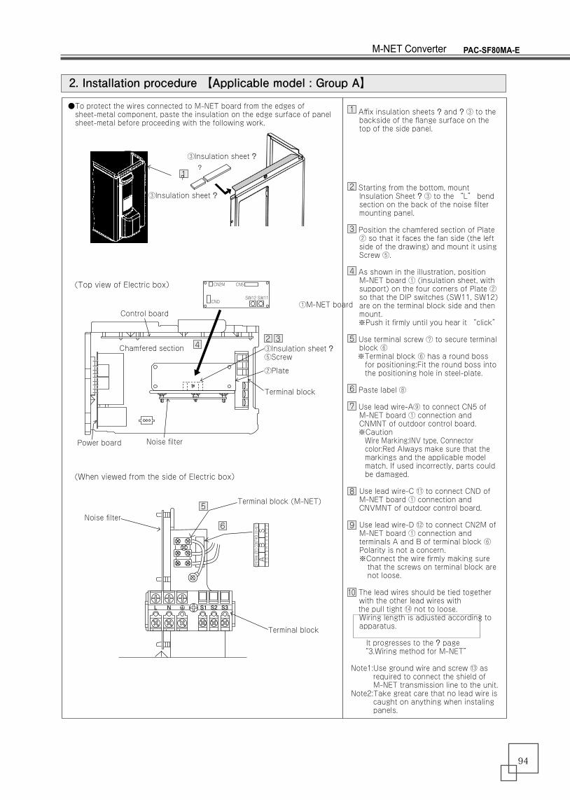
2. Installation procedure 【Applicable model : Group A】
Affix insulation sheets ? and ? ③ to the backside of the flange surface on the top of the side panel.
Starting from the bottom, mount lnsulation Sheet ? ③ to the “L” bend section on the back of the noise filter mounting panel.
Position the chamfered section of Plate ② so that it faces the fan side (the left side of the drawing) and mount it using Screw ⑤.
As shown in the illustration, position M-NET board ① (insulation sheet, with support) on the four corners of Plate ② so that the DIP switches (SW11, SW12) are on the terminal block side and then mount.
※Push it firmly until you hear it “click”
Use terminal screw ⑦ to secure terminal block ⑥
※Terminal block ⑥ has a round boss for positioning:Fit the round boss into the positioning hole in steel-plate.
Paste label ⑧
Use lead wire-A⑨ to connect CN5 of M-NET board ① connection and CNMNT of outdoor control board.
※CautionWire Marking:INV type, Connector color:Red Always make sure that the markings and the applicable model match. If used incorrectly, parts could be damaged.
Use lead wire-C ⑪ to connect CND of M-NET board ① connection and CNVMNT of outdoor control board.
Use lead wire-D ⑫ to connect CN2M of M-NET board ① connection and terminals A and B of terminal block ⑥ Polarity is not a concern.※Connect the wire firmly making sure that the screws on terminal block are not loose.
The lead wires should be tied together with the other lead wires with
the pull tight ⑭ not to loose.Wiring length is adjusted according to apparatus.
It progresses to the ? page “3.Wiring method for M-NET”
Note1:Use ground wire and screw ⑬ as required to connect the shield of M-NET transmission line to the unit.
Note2:Take great care that no lead wire is caught on anything when instaling panels.
1
12
2
3
3
4
45
5
6
6
7
8
9
10
①M-NET board
③Insulation sheet ?⑤Screw
②Plate
Terminal block
Terminal block
●To protect the wires connected to M-NET board from the edges of sheet-metal component, paste the insulation on the edge surface of panel sheet-metal before proceeding with the following work.
?
?
③Insulation sheet ?
③Insulation sheet ?
Control board
(Top view of Electric box)
(When viewed from the side of Electric box)
Chamfered section
Power board
Noise filter
Terminal block (M-NET)
Noise filter
SW12
CN2M
CND
CN5
SW11
CENTRALIZED CONTROL(M-NET)
AB
SBG79H744H02
L N S1 S2 S3
PAC-SF80MA-EM-NET Converter
94
RG79V300H04
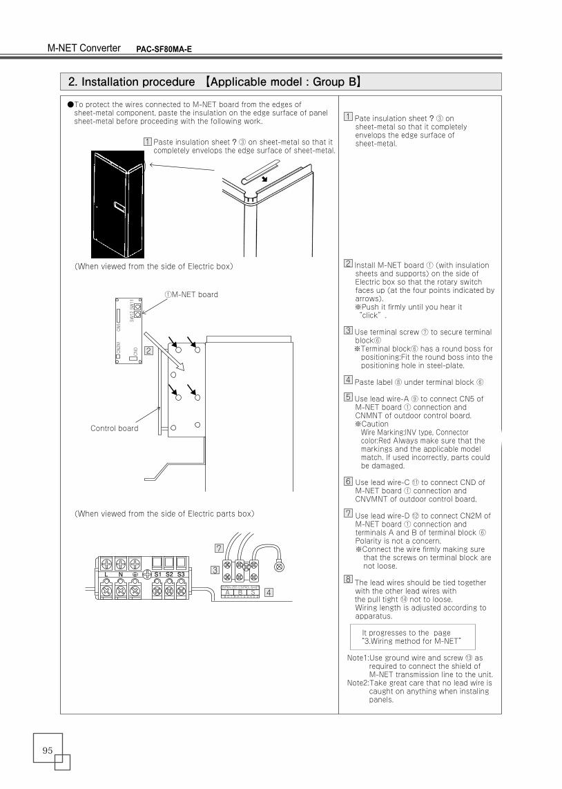
Pate insulation sheet ? ③ on sheet-metal so that it completely envelops the edge surface of sheet-metal.
Install M-NET board ① (with insulation sheets and supports) on the side of Electric box so that the rotary switch faces up (at the four points indicated by arrows).
※Push it firmly until you hear it “click”.
Use terminal screw ⑦ to secure terminal block⑥
※Terminal block⑥ has a round boss for positioning:Fit the round boss into the positioning hole in steel-plate.
Paste label ⑧ under terminal block ⑥
Use lead wire-A ⑨ to connect CN5 of M-NET board ① connection and CNMNT of outdoor control board.
※CautionWire Marking:INV type, Connector color:Red Always make sure that the markings and the applicable model match. If used incorrectly, parts could be damaged.
Use lead wire-C ⑪ to connect CND of M-NET board ① connection and CNVMNT of outdoor control board.
Use lead wire-D ⑫ to connect CN2M of M-NET board ① connection and terminals A and B of terminal block ⑥ Polarity is not a concern.※Connect the wire firmly making sure that the screws on terminal block are not loose.
The lead wires should be tied together with the other lead wires with
the pull tight ⑭ not to loose.Wiring length is adjusted according to apparatus.
It progresses to the page “3.Wiring method for M-NET”
Note1:Use ground wire and screw ⑬ as required to connect the shield of M-NET transmission line to the unit.
Note2:Take great care that no lead wire is caught on anything when instaling panels.
2. Installation procedure 【Applicable model : Group B】
1
2
2
3
3
4
5
6
7
8
7
4
The M-NET board ① is installed in the bottom of electric box so that the DIP switches (SW11,SW12) come front.
※Push it firmly until you hear it “click”.
Use terminal screw ⑦ to secure terminal block⑥
※Terminal block⑥ has a round boss for positioning:Fit the round boss into the positioning hole in steel-plate.
Paste label ⑧ under terminal block ⑥
Use lead wire-B ⑩ to connect CN5 of M-NET board ① connection and CNMNT of outdoor control board.
※CautionWire Marking:NON-INV, Connector color:White Always make sure that the markings and the applicable model match. If used incorrectly, parts could be damaged.
Use lead wire-C ⑪ to connect CND of M-NET board ① connection and CNVMNT of outdoor control board.
Use lead wire-D ⑫ to connect CN2M of M-NET board ① connection and terminals A and B of terminal block ⑥ Polarity is not a concern.※Connect the wire firmly making sure that the screws on terminal block are not loose.
The lead wires should be tied together with the other lead wires with
the pull tight ⑭ not to loose.Wiring length is adjusted according to apparatus.
It progresses to the ? page “3.Wiring method for M-NET”
Note1:Use ground wire and screw ⑬ as required to connect the shield of M-NET transmission line to the unit.
Note2:Take great care that no lead wire is caught on anything when instaling panels.
2. Installation procedure 【Applicable model : Group G】
1
2
3
4
5
6
7
1
①M-NET board
Control board
●To protect the wires connected to M-NET board from the edges of sheet-metal component, paste the insulation on the edge surface of panel sheet-metal before proceeding with the following work.
Paste insulation sheet ? ③ on sheet-metal so that it completely envelops the edge surface of sheet-metal.
(When viewed from the side of Electric box)
(When viewed from the side of Electric parts box)
CENTRALIZED CONTROL(M-NET)A B SBG7 9 H 7 4 4 H 0 2
L N S1 S2 S3
SW12
CN2M
CND
CN5
SW11
2
3
1①M-NET board
Control board
(Top view of Electric box without top panel)
(Front view of Electric box)
⑥Terminal block (M-NET)
CN2M
CND
CN5
SW12 SW11
CENTRALIZED CONTROL(M-NET)A B S
BG79H744H02
CN2M
CND
CN5
SW12 SW11
PAC-SF80MA-EM-NET Converter
95
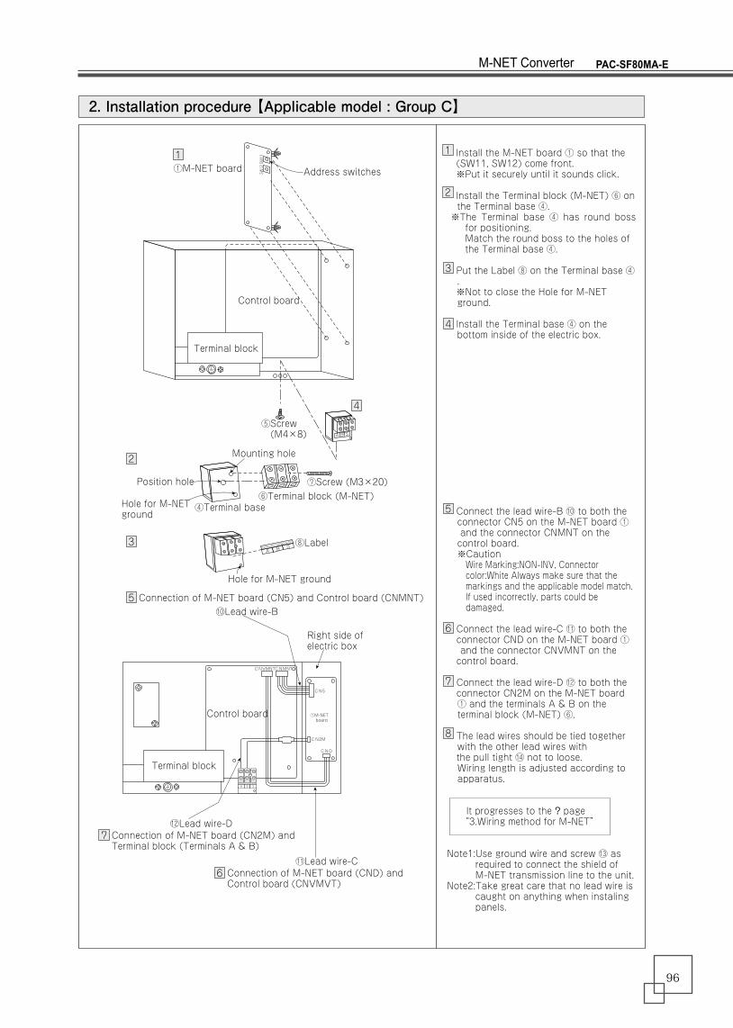
2. Installation procedure 【Applicable model : Group C】
SW12SW11
A B S
Position hole
Hole for M-NET ground
CENTRALIZED CONTR
OL(M-NET)
A B S
①M-NET board Address switches
Control board
Terminal block
⑤Screw (M4×8)
⑦Screw (M3×20)
Hole for M-NET ground
⑧Label
⑥Terminal block (M-NET)④Terminal base
Mounting hole
Install the M-NET board ① so that the (SW11, SW12) come front. ※Put it securely until it sounds click.
Install the Terminal block (M-NET) ⑥ on the Terminal base ④.
※The Terminal base ④ has round boss for positioning. Match the round boss to the holes of the Terminal base ④.
Put the Label ⑧ on the Terminal base ④.
※Not to close the Hole for M-NET ground.
Install the Terminal base ④ on the bottom inside of the electric box.
Connect the lead wire-B ⑩ to both the connector CN5 on the M-NET board ① and the connector CNMNT on the control board.※CautionWire Marking:NON-INV, Connector color:White Always make sure that the markings and the applicable model match. If used incorrectly, parts could be damaged.
Connect the lead wire-C ⑪ to both the connector CND on the M-NET board ① and the connector CNVMNT on the
control board.
Connect the lead wire-D ⑫ to both the connector CN2M on the M-NET board ① and the terminals A & B on the terminal block (M-NET) ⑥.
The lead wires should be tied together with the other lead wires with
the pull tight ⑭ not to loose.Wiring length is adjusted according to apparatus.
It progresses to the ? page “3.Wiring method for M-NET”
Note1:Use ground wire and screw ⑬ as required to connect the shield of M-NET transmission line to the unit.
Note2:Take great care that no lead wire is caught on anything when instaling panels.
2
2
3
5
7
6
11
3
4
4
5
6
7
8
A B S
CN5
CN2M
CNMNTCNVMNT
CND
CENTRALIZED CONTROL(M-NET)
Control board
Terminal block
Connection of M-NET board (CN5) and Control board (CNMNT)
Connection of M-NET board (CN2M) and Terminal block (Terminals A & B)
Connection of M-NET board (CND) and Control board (CNVMVT)
⑩Lead wire-B
Right side of electric box
①M-NET board
⑫Lead wire-D
⑪Lead wire-C
PAC-SF80MA-EM-NET Converter
96
2. Installation procedure 【Applicable model : Group E】
CENTRALIZED CONTROL(M-NET)A B S
BG79H744H02
SW12
CN2M
CND
CN5
SW11
4
3
1
2
⑧Label
⑬Ground wire
Control board
⑦Terminal screw⑥Terminal block
⑤Screws⑮Plate2
①M-NET board
Attach the Plate 2 ⑮, using two screws⑤.
Install M-NET board ① (with insulation sheets and supports) on the Plate2 ⑮ .
※Push it firmly until you hear it “click”.
Use terminal screw ⑦ to secure terminal block⑥
※Terminal block⑥ has a round boss for positioning:Fit the round boss into the positioning hole in steel-plate.
Paste label ⑧
Use lead wire-A ⑨ to connect CN5 of M-NET board ① connection and CNMNT of outdoor control board.
※CautionWire Marking:INV type, Connector color:Red Always make sure that the markings and the applicable model match. If used incorrectly, parts could be damaged.
Use lead wire-C ⑪ to connect CND of M-NET board ① connection and CNVMNT of outdoor control board.
Use lead wire-D ⑫ to connect CN2M of M-NET board ① connection and terminals A and B of terminal block ⑥ Polarity is not a concern.※Connect the wire firmly making sure that the screws on terminal block are not loose.
The lead wires should be tied together with the other lead wires with
the pull tight ⑭ not to loose.Wiring length is adjusted according to apparatus.
It progresses to the ? page “3.Wiring method for M-NET”
Note1:Use ground wire and screw ⑬ as required to connect the shield of M-NET transmission line to the unit.
Note2:Take great care that no lead wire is caught on anything when instaling panels.
1
2
3
4
5
6
7
8
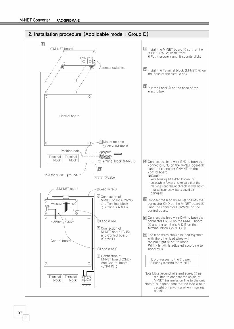
2. Installation procedure 【Applicable model : Group D】
Install the M-NET board ① so that the (SW11, SW12) come front. ※Put it securely until it sounds click.
Install the Terminal block (M-NET) ⑥ on the base of the electric box.
Put the Label ⑧ on the base of the electric box.
Connect the lead wire-B ⑩ to both the connector CN5 on the M-NET board ① and the connector CNMNT on the control board.※CautionWire Marking:NON-INV, Connector color:White Always make sure that the markings and the applicable model match. If used incorrectly, parts could be damaged.
Connect the lead wire-C ⑪ to both the connector CND on the M-NET board ① and the connector CNVMNT on the
control board.
Connect the lead wire-D ⑫ to both the connector CN2M on the M-NET board ① and the terminals A & B on the terminal block (M-NET) ⑥.
The lead wires should be tied together with the other lead wires with
the pull tight ⑭ not to loose.Wiring length is adjusted according to apparatus.
It progresses to the ? page “3.Wiring method for M-NET”
Note1:Use ground wire and screw ⑬ as required to connect the shield of M-NET transmission line to the unit.
Note2:Take great care that no lead wire is caught on anything when instaling panels.
1
2
3
6
4
5
1
2
3
4
5
6
7
Hole for M-NET ground
Position hole
Terminalblock
Terminalblock
①M-NET board
Control board
⑧Label
⑥Terminal block (M-NET)
⑦Screw (M3×20)Mounting hole
A B S
Address switches
SW12 SW11
Control board
Terminalblock
Terminalblock
Connection of M-NET board (CN5) and Control board(CNMNT)
Connection of M-NET board (CND) and Control board (CNVMNT)
Connection of M-NET board (CN2M) and Terminal block (Terminals A & B)
⑩Lead wire-B
⑫Lead wire-D①M-NET board
CNDCN2M CN5
⑪Lead wire-C
A B S
CNVMNT CNMNT
PAC-SF80MA-EM-NET Converter
97

2. Installation procedure 【Applicable model : Group E】
CENTRALIZED CONTROL(M-NET)A B S
BG79H744H02
SW12
CN2M
CND
CN5
SW11
4
3
1
2
⑧Label
⑬Ground wire
Control board
⑦Terminal screw⑥Terminal block
⑤Screws⑮Plate2
①M-NET board
Attach the Plate 2 ⑮, using two screws⑤.
Install M-NET board ① (with insulation sheets and supports) on the Plate2 ⑮ .
※Push it firmly until you hear it “click”.
Use terminal screw ⑦ to secure terminal block⑥
※Terminal block⑥ has a round boss for positioning:Fit the round boss into the positioning hole in steel-plate.
Paste label ⑧
Use lead wire-A ⑨ to connect CN5 of M-NET board ① connection and CNMNT of outdoor control board.
※CautionWire Marking:INV type, Connector color:Red Always make sure that the markings and the applicable model match. If used incorrectly, parts could be damaged.
Use lead wire-C ⑪ to connect CND of M-NET board ① connection and CNVMNT of outdoor control board.
Use lead wire-D ⑫ to connect CN2M of M-NET board ① connection and terminals A and B of terminal block ⑥ Polarity is not a concern.※Connect the wire firmly making sure that the screws on terminal block are not loose.
The lead wires should be tied together with the other lead wires with
the pull tight ⑭ not to loose.Wiring length is adjusted according to apparatus.
It progresses to the ? page “3.Wiring method for M-NET”
Note1:Use ground wire and screw ⑬ as required to connect the shield of M-NET transmission line to the unit.
Note2:Take great care that no lead wire is caught on anything when instaling panels.
1
2
3
4
5
6
7
8
PAC-SF80MA-EM-NET Converter
98
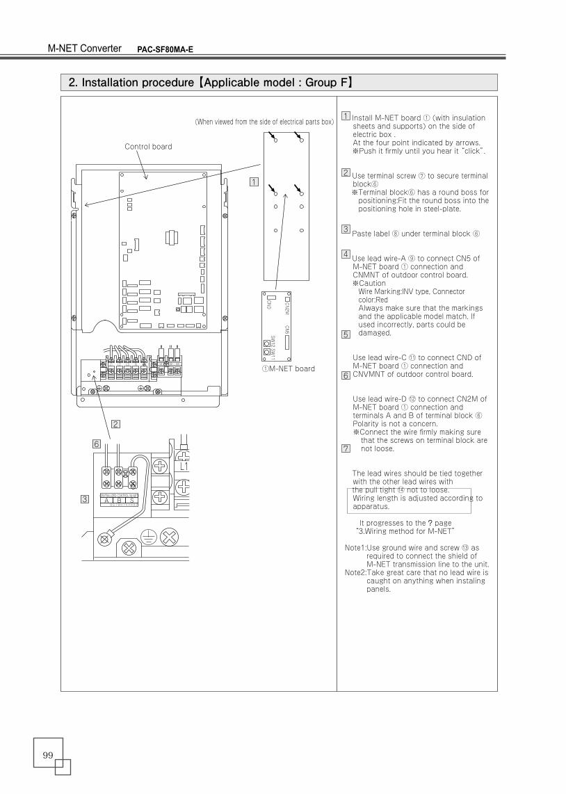
Install M-NET board ① (with insulation sheets and supports) on the side of electric box .At the four point indicated by arrows.
※Push it firmly until you hear it “click”.
Use terminal screw ⑦ to secure terminal block⑥
※Terminal block⑥ has a round boss for positioning:Fit the round boss into the positioning hole in steel-plate.
Paste label ⑧ under terminal block ⑥
Use lead wire-A ⑨ to connect CN5 of M-NET board ① connection and CNMNT of outdoor control board.
※CautionWire Marking:INV type, Connector color:Red Always make sure that the markings and the applicable model match. If used incorrectly, parts could be damaged.
Use lead wire-C ⑪ to connect CND of M-NET board ① connection and CNVMNT of outdoor control board.
Use lead wire-D ⑫ to connect CN2M of M-NET board ① connection and terminals A and B of terminal block ⑥ Polarity is not a concern.※Connect the wire firmly making sure that the screws on terminal block are not loose.
The lead wires should be tied together with the other lead wires with
the pull tight ⑭ not to loose.Wiring length is adjusted according to apparatus.
It progresses to the ? page “3.Wiring method for M-NET”
Note1:Use ground wire and screw ⑬ as required to connect the shield of M-NET transmission line to the unit.
Note2:Take great care that no lead wire is caught on anything when instaling panels.
2. Installation procedure 【Applicable model : Group F】
1
2
3
4
5
6
7
SW12
CN2M
CND
CN5
SW11
1
Control board
(When viewed from the side of electrical parts box)
①M-NET board
2
6
3CENTRALIZED CONTROL(M-NET)A B S
BG79H744H02
L1 L2 L3 N S1 S2 S3
L1
2. Installation procedure 【Applicable model : Group C】
SW12SW11
A B S
Position hole
Hole for M-NET ground
CENTRALIZED CONTR
OL(M-NET)
A B S
①M-NET board Address switches
Control board
Terminal block
⑤Screw (M4×8)
⑦Screw (M3×20)
Hole for M-NET ground
⑧Label
⑥Terminal block (M-NET)④Terminal base
Mounting hole
Install the M-NET board ① so that the (SW11, SW12) come front. ※Put it securely until it sounds click.
Install the Terminal block (M-NET) ⑥ on the Terminal base ④.
※The Terminal base ④ has round boss for positioning. Match the round boss to the holes of the Terminal base ④.
Put the Label ⑧ on the Terminal base ④.
※Not to close the Hole for M-NET ground.
Install the Terminal base ④ on the bottom inside of the electric box.
Connect the lead wire-B ⑩ to both the connector CN5 on the M-NET board ① and the connector CNMNT on the control board.※CautionWire Marking:NON-INV, Connector color:White Always make sure that the markings and the applicable model match. If used incorrectly, parts could be damaged.
Connect the lead wire-C ⑪ to both the connector CND on the M-NET board ① and the connector CNVMNT on the
control board.
Connect the lead wire-D ⑫ to both the connector CN2M on the M-NET board ① and the terminals A & B on the terminal block (M-NET) ⑥.
The lead wires should be tied together with the other lead wires with
the pull tight ⑭ not to loose.Wiring length is adjusted according to apparatus.
It progresses to the ? page “3.Wiring method for M-NET”
Note1:Use ground wire and screw ⑬ as required to connect the shield of M-NET transmission line to the unit.
Note2:Take great care that no lead wire is caught on anything when instaling panels.
2
2
3
5
7
6
11
3
4
4
5
6
7
8
A B S
CN5
CN2M
CNMNTCNVMNT
CND
CENTRALIZED CONTROL(M-NET)
Control board
Terminal block
Connection of M-NET board (CN5) and Control board (CNMNT)
Connection of M-NET board (CN2M) and Terminal block (Terminals A & B)
Connection of M-NET board (CND) and Control board (CNVMVT)
⑩Lead wire-B
Right side of electric box
①M-NET board
⑫Lead wire-D
⑪Lead wire-C
PAC-SF80MA-EM-NET Converter
99
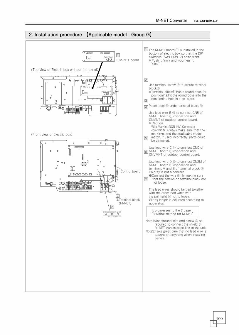
The M-NET board ① is installed in the bottom of electric box so that the DIP switches (SW11,SW12) come front.
※Push it firmly until you hear it “click”.
Use terminal screw ⑦ to secure terminal block⑥
※Terminal block⑥ has a round boss for positioning:Fit the round boss into the positioning hole in steel-plate.
Paste label ⑧ under terminal block ⑥
Use lead wire-B ⑩ to connect CN5 of M-NET board ① connection and CNMNT of outdoor control board.
※CautionWire Marking:NON-INV, Connector color:White Always make sure that the markings and the applicable model match. If used incorrectly, parts could be damaged.
Use lead wire-C ⑪ to connect CND of M-NET board ① connection and CNVMNT of outdoor control board.
Use lead wire-D ⑫ to connect CN2M of M-NET board ① connection and terminals A and B of terminal block ⑥ Polarity is not a concern.※Connect the wire firmly making sure that the screws on terminal block are not loose.
The lead wires should be tied together with the other lead wires with
the pull tight ⑭ not to loose.Wiring length is adjusted according to apparatus.
It progresses to the ? page “3.Wiring method for M-NET”
Note1:Use ground wire and screw ⑬ as required to connect the shield of M-NET transmission line to the unit.
Note2:Take great care that no lead wire is caught on anything when instaling panels.
2. Installation procedure 【Applicable model : Group G】
1
2
3
4
5
6
7
2
3
1①M-NET board
Control board
(Top view of Electric box without top panel)
(Front view of Electric box)
⑥Terminal block (M-NET)
CN2M
CND
CN5
SW12 SW11
CENTRALIZED CONTROL(M-NET)A B S
BG79H744H02
CN2M
CND
CN5
SW12 SW11
PAC-SF80MA-EM-NET Converter
100
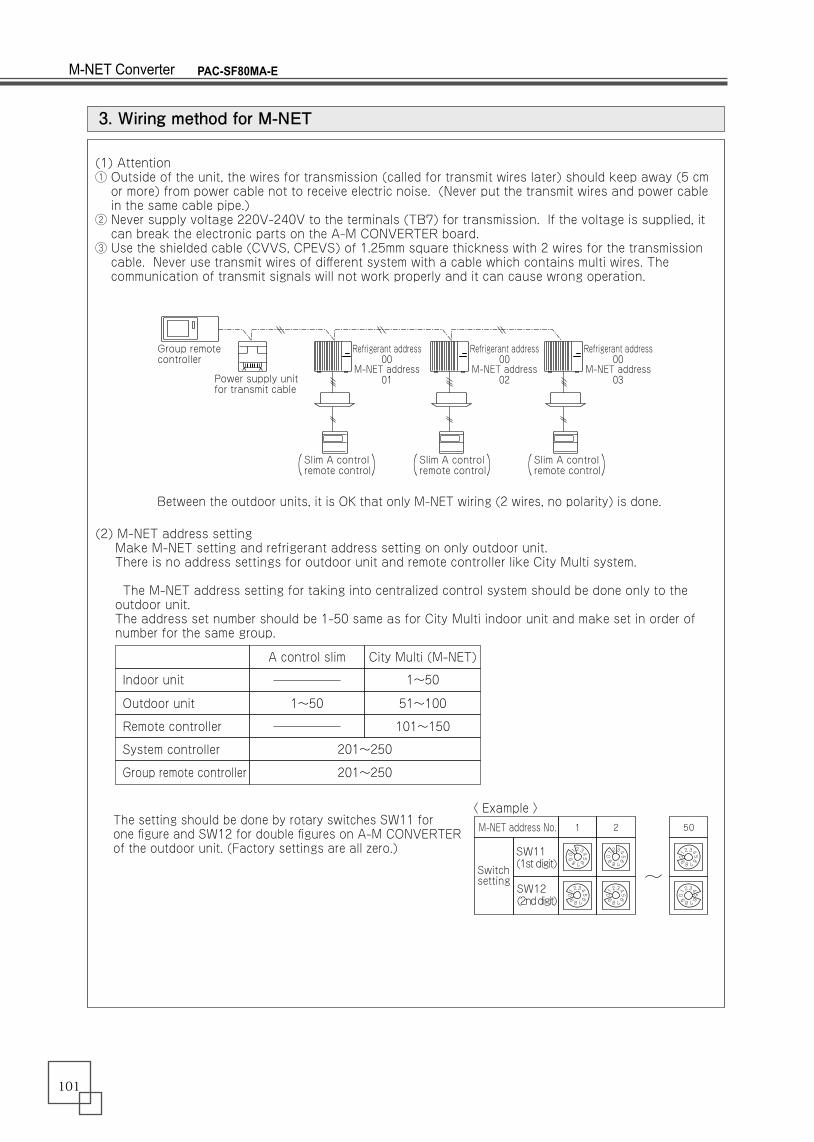
Between the outdoor units, it is OK that only M-NET wiring (2 wires, no polarity) is done.
The setting should be done by rotary switches SW11 for one figure and SW12 for double figures on A-M CONVERTER of the outdoor unit. (Factory settings are all zero.)
(1) Attention① Outside of the unit, the wires for transmission (called for transmit wires later) should keep away (5 cm or more) from power cable not to receive electric noise. (Never put the transmit wires and power cable in the same cable pipe.)② Never supply voltage 220V-240V to the terminals (TB7) for transmission. If the voltage is supplied, it can break the electronic parts on the A-M CONVERTER board.③ Use the shielded cable (CVVS, CPEVS) of 1.25mm square thickness with 2 wires for the transmission cable. Never use transmit wires of different system with a cable which contains multi wires. The communication of transmit signals will not work properly and it can cause wrong operation.
(2) M-NET address setting Make M-NET setting and refrigerant address setting on only outdoor unit. There is no address settings for outdoor unit and remote controller like City Multi system. The M-NET address setting for taking into centralized control system should be done only to the outdoor unit. The address set number should be 1-50 same as for City Multi indoor unit and make set in order of number for the same group.
3. Wiring method for M-NET
Group remote controller
Power supply unitfor transmit cable
Refrigerant address00
M-NET address01
Refrigerant address00
M-NET address02
Refrigerant address00
M-NET address03
Slim A controlremote control
Indoor unit
Outdoor unit 1~50 51~100
Remote controller 101~150
201~250
201~250
System controller
1~50
Group remote controller
A control slim City Multi (M-NET)
1M-NET address No. 2 50
0
12345
6789 012
3456789
012
3456789
012
3456789
012
3456789
012
3456789
SW11 (1st digit)
SW12(2nd digit)
〈 Example 〉
Switch setting
( ) Slim A controlremote control( ) Slim A control
remote control( )
PAC-SF80MA-EM-NET Converter
101
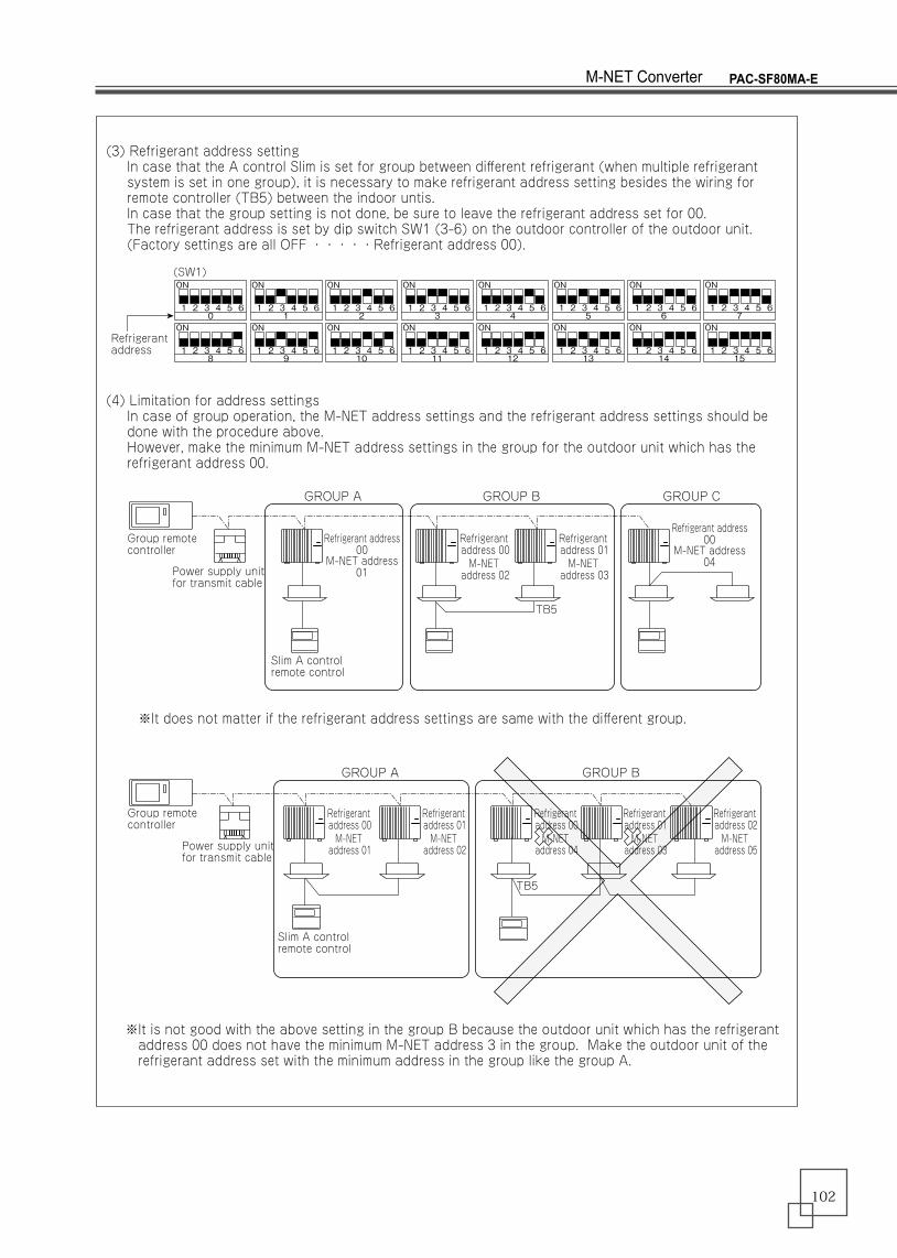
(3) Refrigerant address setting In case that the A control Slim is set for group between different refrigerant (when multiple refrigerant system is set in one group), it is necessary to make refrigerant address setting besides the wiring for remote controller (TB5) between the indoor untis. In case that the group setting is not done, be sure to leave the refrigerant address set for 00. The refrigerant address is set by dip switch SW1 (3-6) on the outdoor controller of the outdoor unit. (Factory settings are all OFF ・・・・・Refrigerant address 00).
(4) Limitation for address settings In case of group operation, the M-NET address settings and the refrigerant address settings should be done with the procedure above. However, make the minimum M-NET address settings in the group for the outdoor unit which has the refrigerant address 00.
※It does not matter if the refrigerant address settings are same with the different group.
※It is not good with the above setting in the group B because the outdoor unit which has the refrigerant address 00 does not have the minimum M-NET address 3 in the group. Make the outdoor unit of the refrigerant address set with the minimum address in the group like the group A.
Group remote controller
GROUP A
GROUP A GROUP B
GROUP B GROUP C
Power supply unitfor transmit cable
Refrigerant address00
M-NET address01
Refrigerant address00
M-NET address04
Refrigerant address 00M-NET address 02
Refrigerant address 00M-NET address 01
Refrigerant address 01M-NET address 02
Refrigerant address 01M-NET address 03
Slim A controlremote control
Group remote controller
Power supply unitfor transmit cable
Slim A controlremote control
TB5
TB5
Refrigerant address 00M-NET address 04
Refrigerant address 01M-NET address 03
Refrigerant address 02M-NET address 05
Refrigerantaddress
(SW1)
1 2 3 4 5 6
ON
01 2 3 4 5 6
ON
11 2 3 4 5 6
ON
21 2 3 4 5 6
ON
31 2 3 4 5 6
ON
41 2 3 4 5 6
ON
5
1 2 3 4 5 6
ON
81 2 3 4 5 6
ON
91 2 3 4 5 6
ON
101 2 3 4 5 6
ON
111 2 3 4 5 6
ON
121 2 3 4 5 6
ON
13
1 2 3 4 5 6
ON
61 2 3 4 5 6
ON
7
1 2 3 4 5 6
ON
141 2 3 4 5 6
ON
15
PAC-SF80MA-EM-NET Converter
102
103
Centralized control remote controller
Centralized control remote controller
Centralized control remote controller
Outdoor unit corresponds to M-NET
Outdoor unit corresponds to M-NET
Outdoor unit corresponds to M-NET
Outdoor unit corresponds to M-NET
Outdoor unit corresponds to M-NET
Power supply unit
○Good example (One spot ground of shielded wire)
○Good example (One spot ground of shielded wire)※
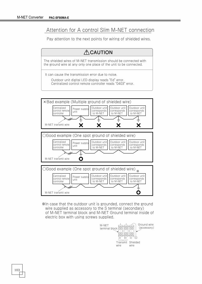
CAUTION
A B S
M-NET terminal block
Ground wire (accessory)
Transmit wire
Shielded wire
It can cause the transmission error due to noise.
Outdoor unit digital LED display reads "Ed" error. Centralized control remote controller reads "0403" error.
Attention for A control Slim M-NET connection
Pay attention to the next points for wiring of shielded wires.
×Bad example (Multiple ground of shielded wire)
M-NET transmit wire
Power supply unit
M-NET transmit wire
Outdoor unit corresponds to M-NET
Outdoor unit corresponds to M-NET
Outdoor unit corresponds to M-NET
Outdoor unit corresponds to M-NET
Power supply unit
M-NET transmit wire
※In case that the outdoor unit is grounded, connect the ground wire supplied as accessory to the S terminal (secondary) of M-NET terminal block and M-NET Ground terminal inside of electric box with using screws supplied.
The shielded wires of M-NET transmission should be connected with the ground wire at any only one place of the unit to be connected.
PAC-SF80MA-EM-NET Converter