sheet metal working - nathi | loves jesus · pdf filesheet metal forming • sheet metal...
TRANSCRIPT
Production Engineering II
AAiT
2.2 Sheet Metal Working
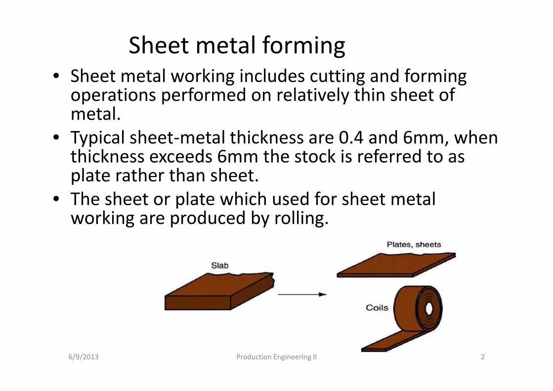
Sheet metal forming • Sheet metal working includes cutting and forming
operations performed on relatively thin sheet of metal.
• Typical sheet-metal thickness are 0.4 and 6mm, when thickness exceeds 6mm the stock is referred to as plate rather than sheet.
• The sheet or plate which used for sheet metal working are produced by rolling.
6/9/2013 2Production Engineering II
Parts made by sheet and plate metal:
• Automobile bodies, airplanes, railway cars,
locomotives, farm and construction equipment
,appliances, office furniture and etc.
Advantages of sheet metal working:
�High strength, good dimensional accuracy, good
surface finish, relatively low cost.
�For components that must be made in large
quantities, economical mass production can be
designed.
6/9/2013 3Production Engineering II
• Most sheet metal processing is performed at room temperature (cold working), except when the stock is thick, the metal is brittle, or the deformation is significant it uses warm or hot working.
• Most sheet metal operations are performed on machine tools called presses. The term stamping press is used to distinguish this presses from forging & extrusion presses.
• The tooling that performs sheet metal work is called a punch-and die. To facilitate mass production, the sheet metal is often presented to the press as long stripes or coils.
6/9/2013 4Production Engineering II
Sheet metal working
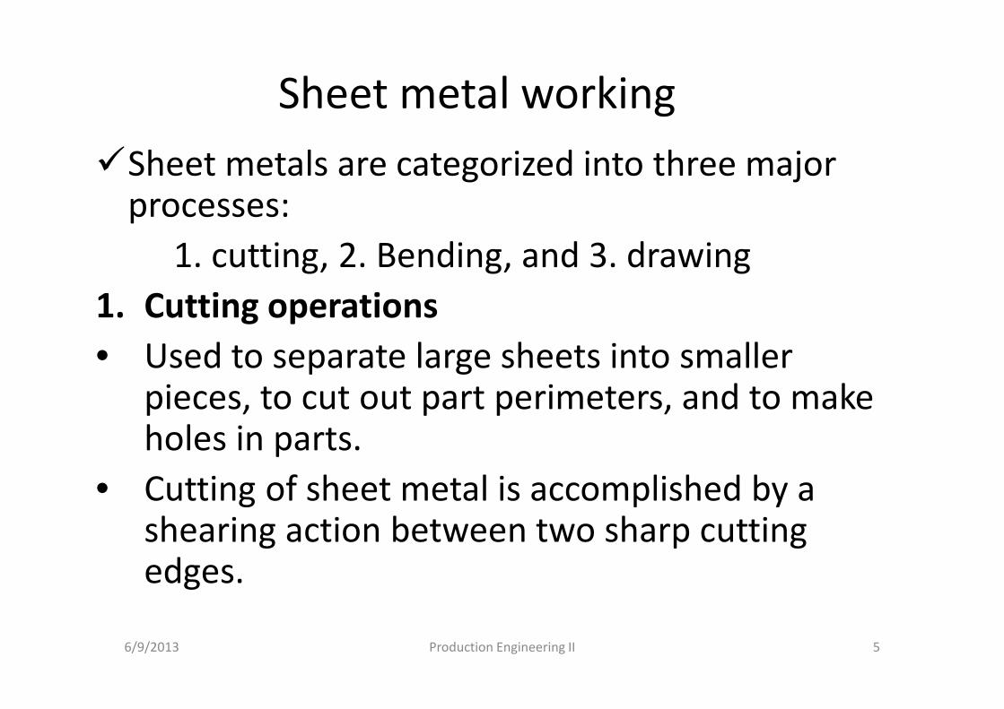
�Sheet metals are categorized into three major processes:
1. cutting, 2. Bending, and 3. drawing
1. Cutting operations
• Used to separate large sheets into smaller pieces, to cut out part perimeters, and to make holes in parts.
• Cutting of sheet metal is accomplished by a shearing action between two sharp cutting edges.
6/9/2013 5Production Engineering II
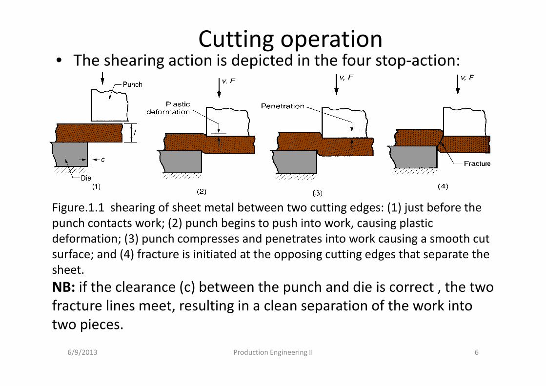
Cutting operation• The shearing action is depicted in the four stop-action:
6/9/2013 6Production Engineering II
Figure.1.1 shearing of sheet metal between two cutting edges: (1) just before the
punch contacts work; (2) punch begins to push into work, causing plastic
deformation; (3) punch compresses and penetrates into work causing a smooth cut
surface; and (4) fracture is initiated at the opposing cutting edges that separate the
sheet.
NB: if the clearance (c) between the punch and die is correct , the two
fracture lines meet, resulting in a clean separation of the work into
two pieces.
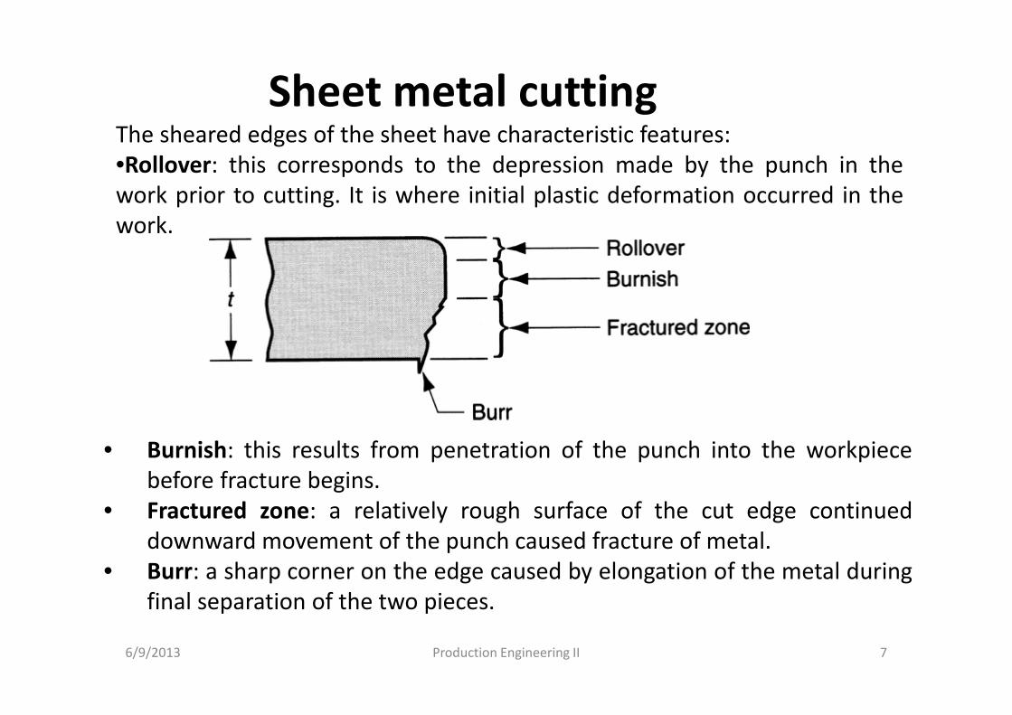
Sheet metal cuttingThe sheared edges of the sheet have characteristic features:
•Rollover: this corresponds to the depression made by the punch in the
work prior to cutting. It is where initial plastic deformation occurred in the
work.
• Burnish: this results from penetration of the punch into the workpiece
before fracture begins.
• Fractured zone: a relatively rough surface of the cut edge continued
downward movement of the punch caused fracture of metal.
• Burr: a sharp corner on the edge caused by elongation of the metal during
final separation of the two pieces.
6/9/2013 7Production Engineering II
Cutting • There are three principal operations in press working
that cut metal by the shearing mechanism: shearing, blanking, and punching.
a. Shearing is a sheet metal cutting operation along a straight line between two cutting edges.
� Shearing is typically used to cut large sheets into smaller sections for subsequent press working operations.
� It is performed on a machine called a power shears, or squaring shears. The upper blade of the power shears is often inclined to reduce the required cutting force.
6/9/2013 8Production Engineering II
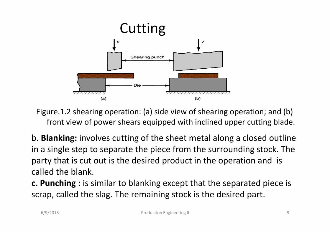
Cutting
Figure.1.2 shearing operation: (a) side view of shearing operation; and (b)
front view of power shears equipped with inclined upper cutting blade.
6/9/2013 9Production Engineering II
b. Blanking: involves cutting of the sheet metal along a closed outline
in a single step to separate the piece from the surrounding stock. The
party that is cut out is the desired product in the operation and is
called the blank.
c. Punching : is similar to blanking except that the separated piece is
scrap, called the slag. The remaining stock is the desired part.
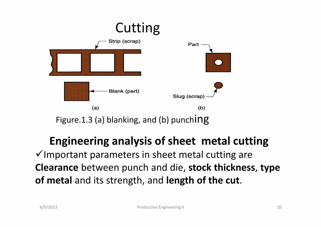
Cutting
Figure.1.3 (a) blanking, and (b) punching
6/9/2013 10Production Engineering II
Engineering analysis of sheet metal cutting�Important parameters in sheet metal cutting are
Clearance between punch and die, stock thickness, type
of metal and its strength, and length of the cut.
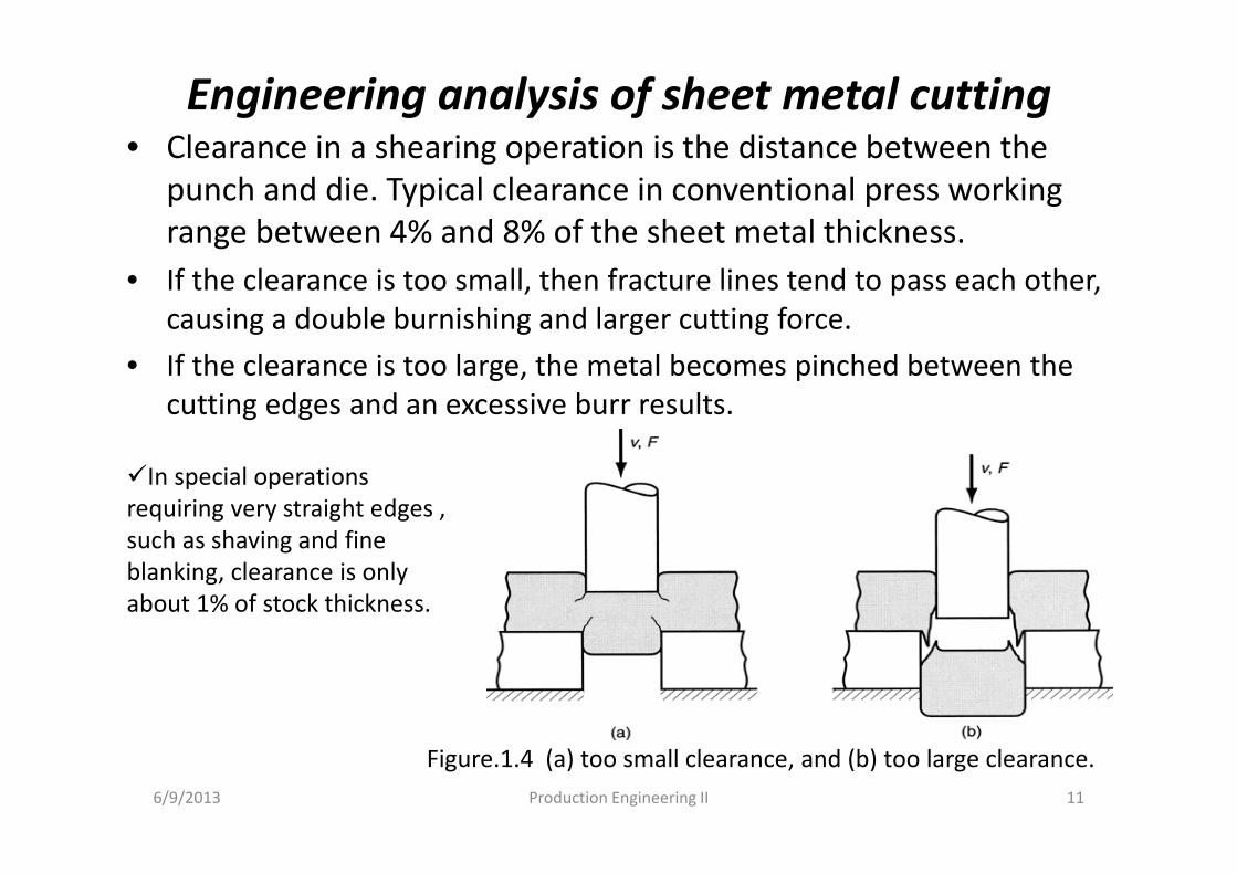
Engineering analysis of sheet metal cutting• Clearance in a shearing operation is the distance between the
punch and die. Typical clearance in conventional press working
range between 4% and 8% of the sheet metal thickness.
• If the clearance is too small, then fracture lines tend to pass each other,
causing a double burnishing and larger cutting force.
• If the clearance is too large, the metal becomes pinched between the
cutting edges and an excessive burr results.
6/9/2013 11Production Engineering II
�In special operations
requiring very straight edges ,
such as shaving and fine
blanking, clearance is only
about 1% of stock thickness.
Figure.1.4 (a) too small clearance, and (b) too large clearance.
Engineering analysis of sheet metal cutting
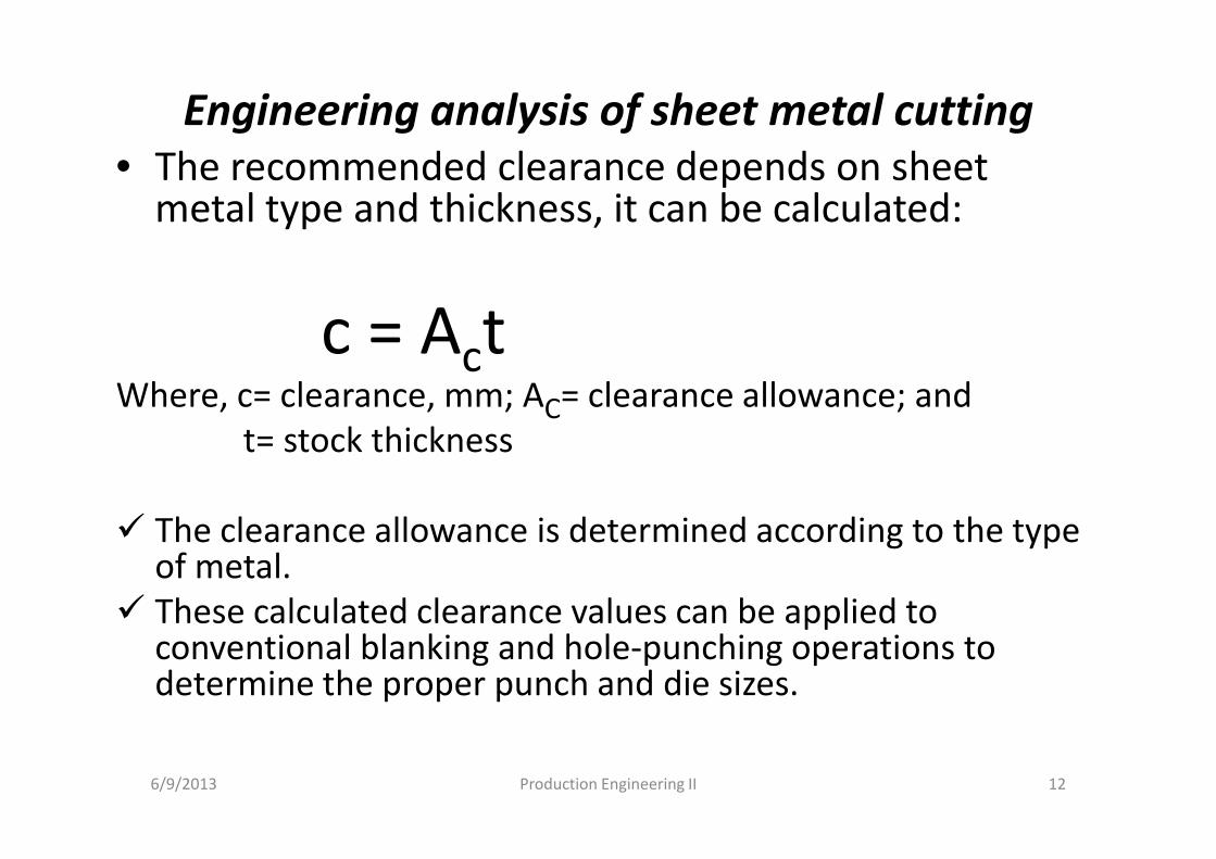
• The recommended clearance depends on sheet metal type and thickness, it can be calculated:
c = ActWhere, c= clearance, mm; AC= clearance allowance; and
t= stock thickness
� The clearance allowance is determined according to the type of metal.
� These calculated clearance values can be applied to conventional blanking and hole-punching operations to determine the proper punch and die sizes.
6/9/2013 Production Engineering II 12
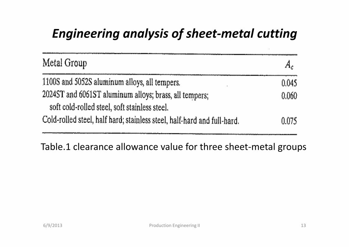
Engineering analysis of sheet-metal cutting
Table.1 clearance allowance value for three sheet-metal groups
6/9/2013 Production Engineering II 13
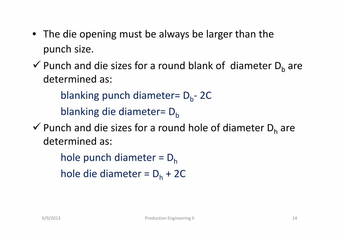
• The die opening must be always be larger than the
punch size.
� Punch and die sizes for a round blank of diameter Db are
determined as:
blanking punch diameter= Db- 2C
blanking die diameter= Db
� Punch and die sizes for a round hole of diameter Dh are
determined as:
hole punch diameter = Dh
hole die diameter = Dh + 2C
6/9/2013 Production Engineering II 14
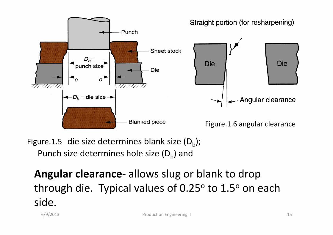
Figure.1.5 die size determines blank size (Db);
Punch size determines hole size (Dh) and
6/9/2013 Production Engineering II 15
Angular clearance- allows slug or blank to drop
through die. Typical values of 0.25o to 1.5o on each
side.
Figure.1.6 angular clearance
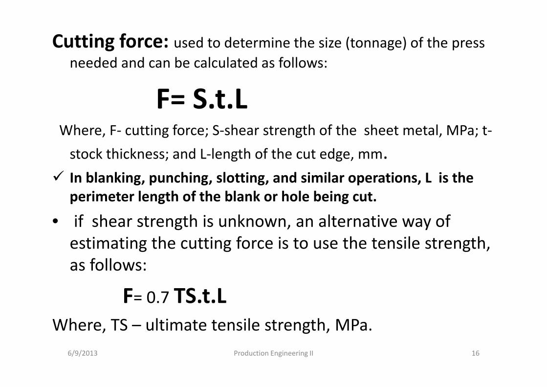
Cutting force: used to determine the size (tonnage) of the press
needed and can be calculated as follows:
F= S.t.LWhere, F- cutting force; S-shear strength of the sheet metal, MPa; t-
stock thickness; and L-length of the cut edge, mm.
� In blanking, punching, slotting, and similar operations, L is the
perimeter length of the blank or hole being cut.
• if shear strength is unknown, an alternative way of
estimating the cutting force is to use the tensile strength,
as follows:
F= 0.7 TS.t.L
Where, TS – ultimate tensile strength, MPa.
6/9/2013 Production Engineering II 16
Other sheet-metal cutting operations
a. Cut off: is a shearing operation in which blanks are separated from a sheet-metal strip by cutting the opposite sides of the part in sequence.
b. Parting: cutting a sheet-metal strip by a punch with two cutting edges that match the opposite sides of the blank.
c. Shaving: performed with very small clearance to obtain accurate dimensions and cut edges that are smooth and straight.
d. Fine blanking: used to blank sheet-metal parts with close tolerances and smooth, straight edges in one step.
6/9/2013 Production Engineering II 17
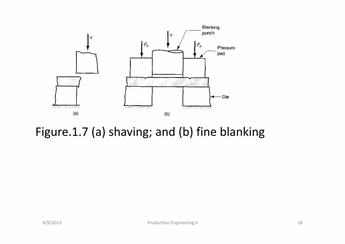
Figure.1.7 (a) shaving; and (b) fine blanking
6/9/2013 Production Engineering II 18
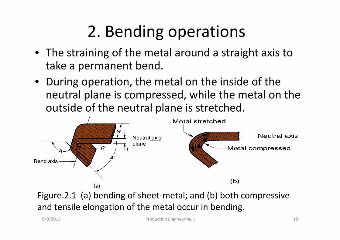
2. Bending operations • The straining of the metal around a straight axis to
take a permanent bend.
• During operation, the metal on the inside of the neutral plane is compressed, while the metal on the outside of the neutral plane is stretched.
6/9/2013 Production Engineering II 19
Figure.2.1 (a) bending of sheet-metal; and (b) both compressive
and tensile elongation of the metal occur in bending.
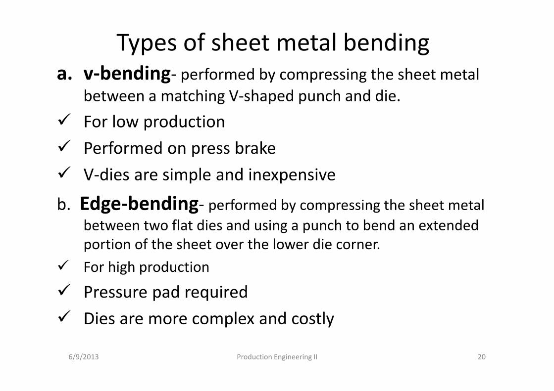
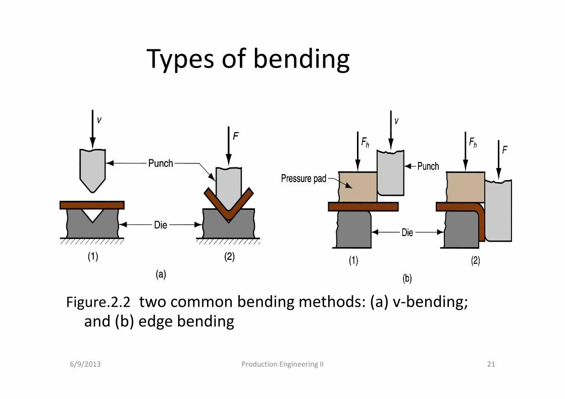
Types of sheet metal bendinga. v-bending- performed by compressing the sheet metal
between a matching V-shaped punch and die.
� For low production
� Performed on press brake
� V-dies are simple and inexpensive
b. Edge-bending- performed by compressing the sheet metal
between two flat dies and using a punch to bend an extended
portion of the sheet over the lower die corner.
� For high production
� Pressure pad required
� Dies are more complex and costly
6/9/2013 Production Engineering II 20
Types of bending
Figure.2.2 two common bending methods: (a) v-bending;
and (b) edge bending
6/9/2013 Production Engineering II 21
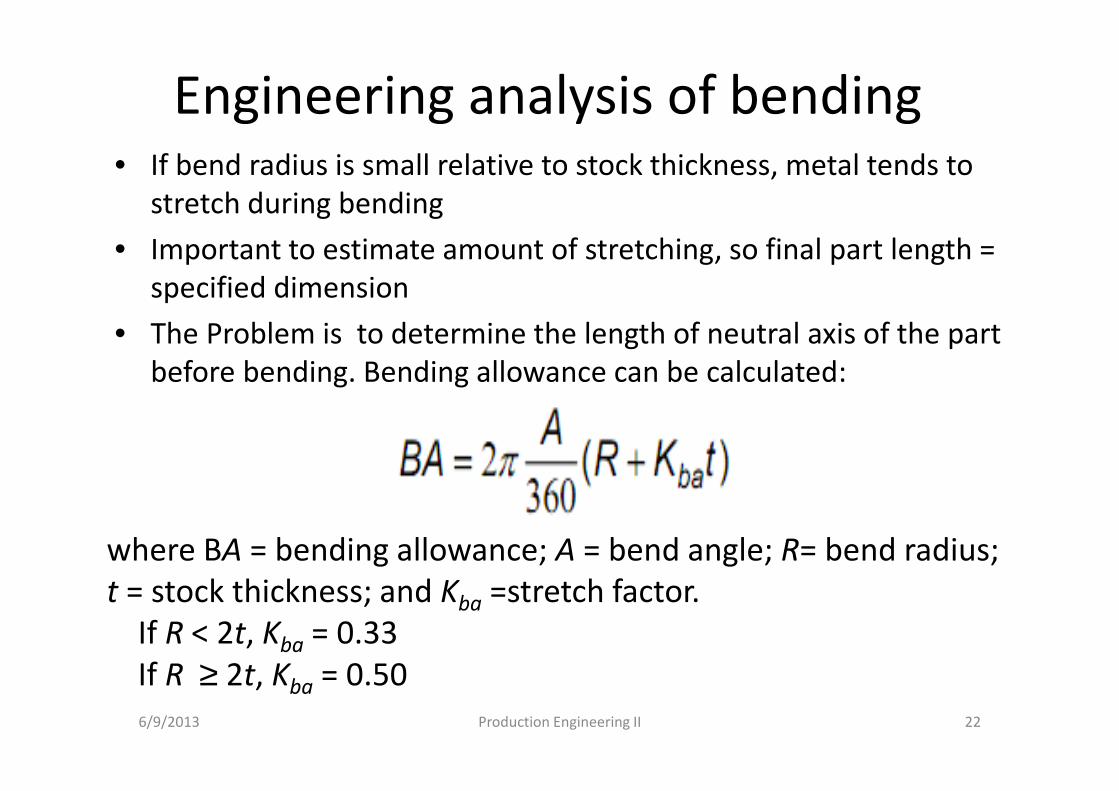
Engineering analysis of bending• If bend radius is small relative to stock thickness, metal tends to
stretch during bending
• Important to estimate amount of stretching, so final part length =
specified dimension
• The Problem is to determine the length of neutral axis of the part
before bending. Bending allowance can be calculated:
6/9/2013 Production Engineering II 22
where BA = bending allowance; A = bend angle; R= bend radius;
t = stock thickness; and Kba =stretch factor.
If R < 2t, Kba = 0.33
If R ≥ 2t, Kba = 0.50
springback
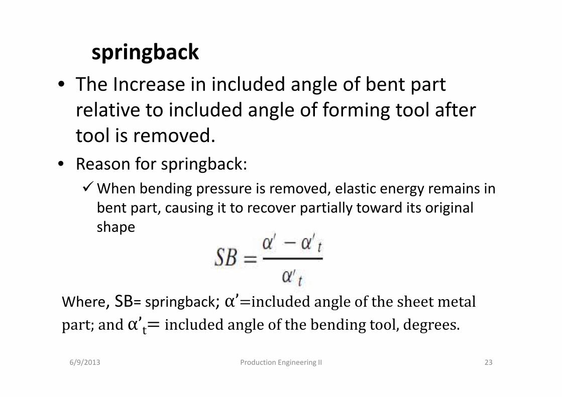
• The Increase in included angle of bent part
relative to included angle of forming tool after
tool is removed.
• Reason for springback:
�When bending pressure is removed, elastic energy remains in
bent part, causing it to recover partially toward its original
shape
6/9/2013 Production Engineering II 23
Where, SB= springback; α’=included angle of the sheet metal
part; and α’t= included angle of the bending tool, degrees.
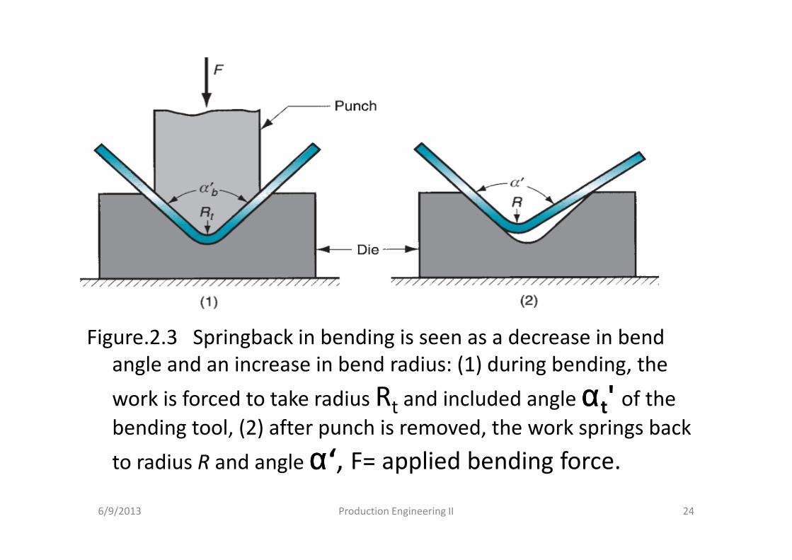
Figure.2.3 Springback in bending is seen as a decrease in bend
angle and an increase in bend radius: (1) during bending, the
work is forced to take radius Rt and included angle ααααt' of the
bending tool, (2) after punch is removed, the work springs back
to radius R and angle αααα‘, F= applied bending force.
6/9/2013 Production Engineering II 24
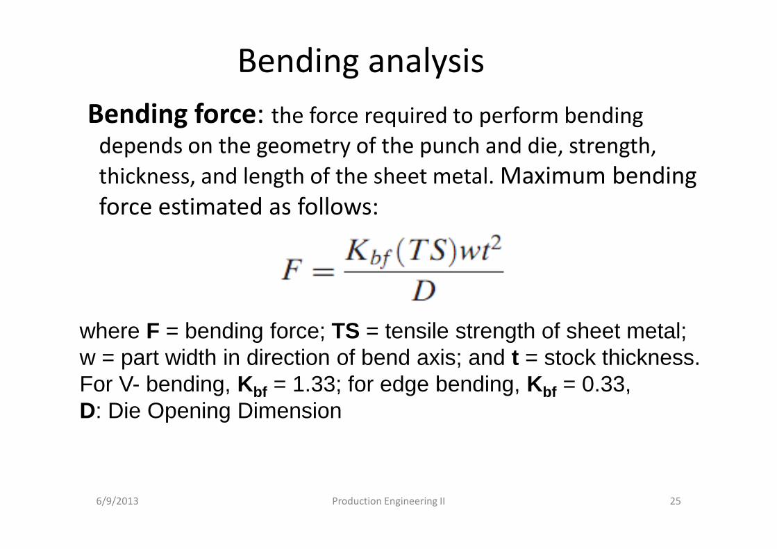
Bending analysis
Bending force: the force required to perform bending
depends on the geometry of the punch and die, strength,
thickness, and length of the sheet metal. Maximum bending
force estimated as follows:
6/9/2013 Production Engineering II 25
where F = bending force; TS = tensile strength of sheet metal; w = part width in direction of bend axis; and t = stock thickness. For V- bending, Kbf = 1.33; for edge bending, Kbf = 0.33, D: Die Opening Dimension
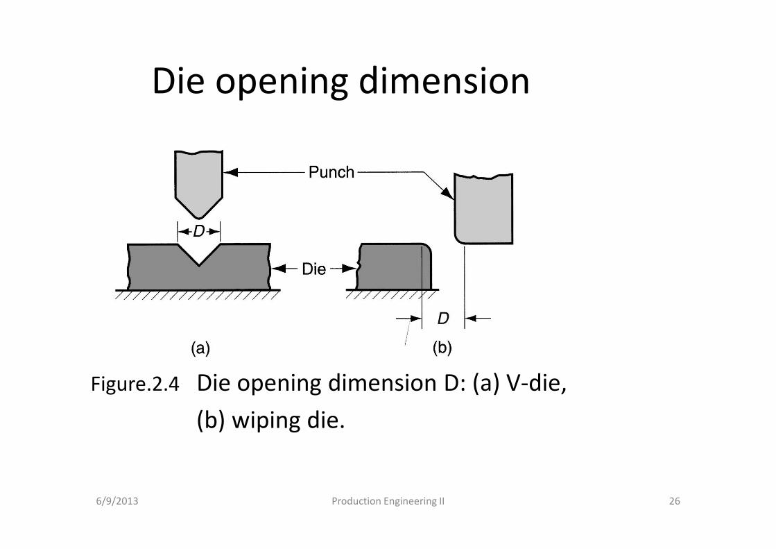
Die opening dimension
Figure.2.4 Die opening dimension D: (a) V-die,
(b) wiping die.
6/9/2013 Production Engineering II 26
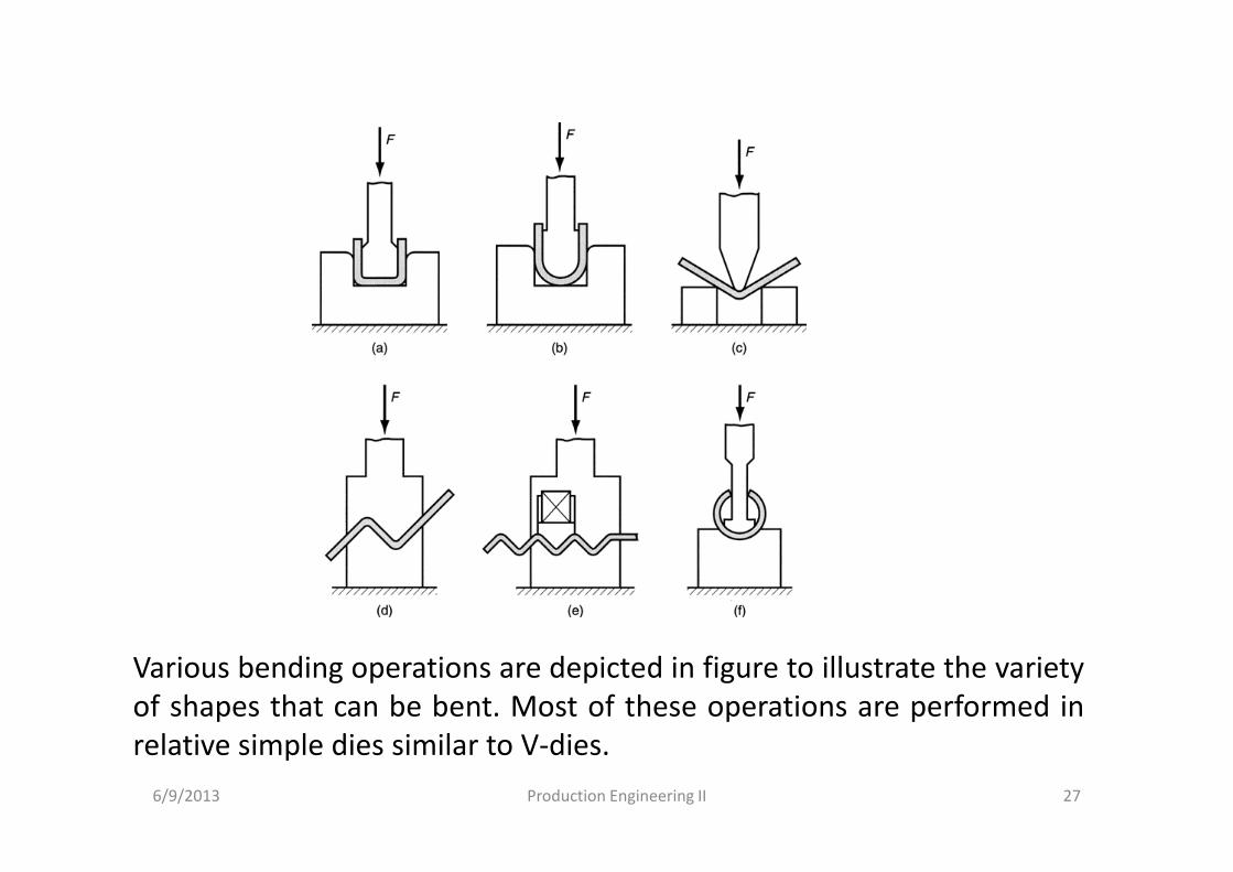
Various bending operations are depicted in figure to illustrate the variety
of shapes that can be bent. Most of these operations are performed in
relative simple dies similar to V-dies.
6/9/2013 27Production Engineering II
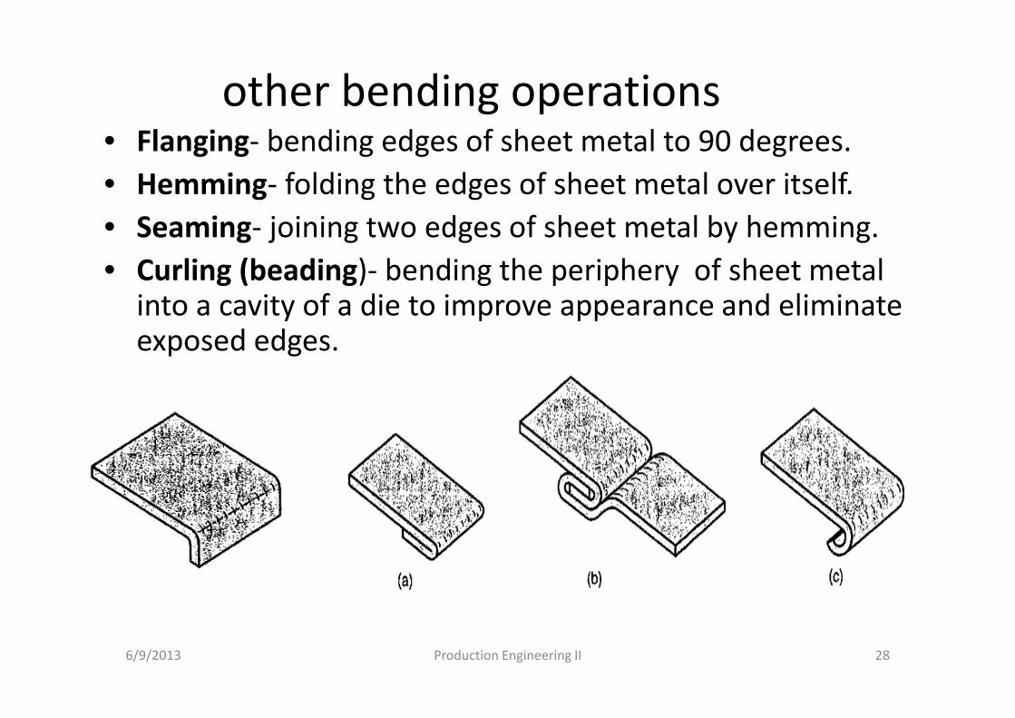
other bending operations• Flanging- bending edges of sheet metal to 90 degrees.
• Hemming- folding the edges of sheet metal over itself.
• Seaming- joining two edges of sheet metal by hemming.
• Curling (beading)- bending the periphery of sheet metal into a cavity of a die to improve appearance and eliminate exposed edges.
6/9/2013 Production Engineering II 28
3. Drawing
Sheet metal forming operation used to make cup
shaped, box shaped, or other complex curved, hollow
shaped parts
• Performed by placing a piece of sheet metal over a die
cavity and then pushing the metal into the opening with
a punch.
• Products: beverage cans, ammunition shells,
automobile body panels
• Also known as deep drawing (to distinguish it from wire and bar
drawing)
6/9/2013 Production Engineering II 29
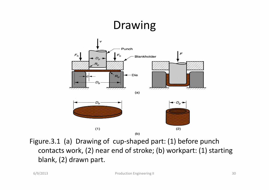
Drawing
Figure.3.1 (a) Drawing of cup-shaped part: (1) before punch
contacts work, (2) near end of stroke; (b) workpart: (1) starting
blank, (2) drawn part.
6/9/2013 Production Engineering II 30
Mechanics of drawing
• Sides of punch and die separated by a
clearance c given by:
c = 1.1 t
where t = stock thickness
• In other words, clearance is about 10% greater
than stock thickness
6/9/2013 Production Engineering II 31
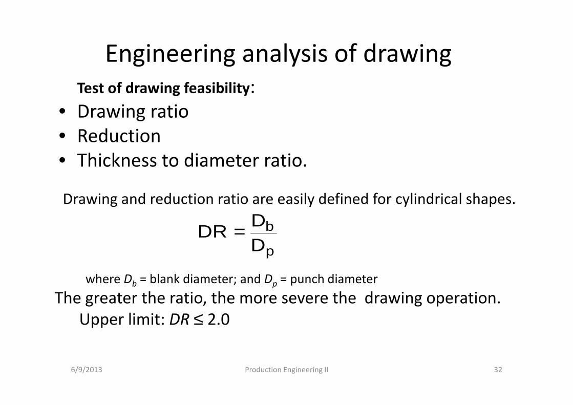
Engineering analysis of drawing
Test of drawing feasibility:
• Drawing ratio
• Reduction
• Thickness to diameter ratio.
6/9/2013 Production Engineering II 32
p
b
DD
DR =
Drawing and reduction ratio are easily defined for cylindrical shapes.
where Db = blank diameter; and Dp = punch diameter
The greater the ratio, the more severe the drawing operation.
Upper limit: DR ≤ 2.0
Engineering analysis of drawing
6/9/2013 Production Engineering II 33
b
pb
D
DDr
−=
Where, r= reduction ratioValue of r should be less than 0.50
Thickness to Diameter Ratio :
Thickness of starting blank divided by blank diameter
� Desirable for t/Db ratio to be greater than 1%
� As t/Db decreases, tendency for wrinkling increases
These are guide lines for Feasibility testing
Engineering analysis of drawing
Blank size determination
• For final dimensions of drawn shape to be correct,
starting blank diameter Db must be right.
• Solve for Db by setting starting sheet metal blank volume =
final product volume.
• To facilitate calculation, assume negligible thinning of
part wall.
6/9/2013 Production Engineering II 34
Engineering analysis of drawing
6/9/2013 Production Engineering II 35
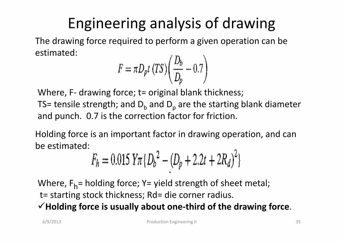
The drawing force required to perform a given operation can be
estimated:
Where, F- drawing force; t= original blank thickness;
TS= tensile strength; and Db and Dp are the starting blank diameter
and punch. 0.7 is the correction factor for friction.
Holding force is an important factor in drawing operation, and can
be estimated:
Where, Fh= holding force; Y= yield strength of sheet metal;
t= starting stock thickness; Rd= die corner radius.
�Holding force is usually about one-third of the drawing force.
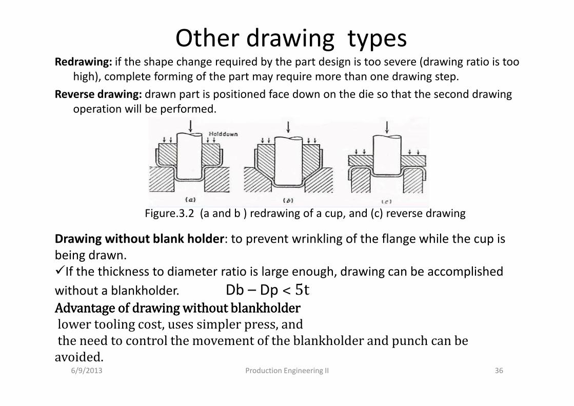
Other drawing typesRedrawing: if the shape change required by the part design is too severe (drawing ratio is too
high), complete forming of the part may require more than one drawing step.
Reverse drawing: drawn part is positioned face down on the die so that the second drawing
operation will be performed.
36
Figure.3.2 (a and b ) redrawing of a cup, and (c) reverse drawing
Drawing without blank holder: to prevent wrinkling of the flange while the cup is
being drawn.
�If the thickness to diameter ratio is large enough, drawing can be accomplished
without a blankholder. Db – Dp ˂ 5tAdvantage of drawing without blankholder Advantage of drawing without blankholder Advantage of drawing without blankholder Advantage of drawing without blankholder
lower tooling cost, uses simpler press, and
the need to control the movement of the blankholder and punch can be
avoided.6/9/2013 Production Engineering II
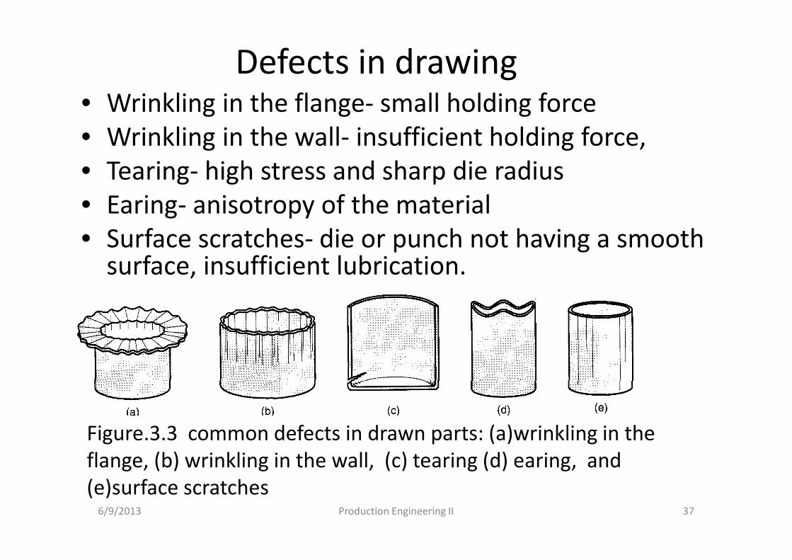
Defects in drawing• Wrinkling in the flange- small holding force
• Wrinkling in the wall- insufficient holding force,
• Tearing- high stress and sharp die radius
• Earing- anisotropy of the material
• Surface scratches- die or punch not having a smooth surface, insufficient lubrication.
6/9/2013 Production Engineering II 37
Figure.3.3 common defects in drawn parts: (a)wrinkling in the
flange, (b) wrinkling in the wall, (c) tearing (d) earing, and
(e)surface scratches
Other sheet metal forming operationsOther sheet metal forming operations performed on
conventional presses:
• Operations performed with metal tooling
• Operations performed with flexible rubber tooling
a. Operations performed on metal tooling includes:
1. Ironing
2. Coining
3. Lancing
4. twisting
6/9/2013 Production Engineering II 38
1. ironing: a continuous thinning process and often
accompanies deep drawing, i.e., thinning of the wall of
a cylindrical cup by passing it through an ironing die.
products: beverage cans, artillery shells,
2. coining: used in sheet metal work to form indentations
and raised sections in the part.
3. Embossing: Used to create indentations in sheet, such
as raised (or indented) lettering or strengthening ribs.
� Embossing dies possess matching cavity contours, the punch containing the
positive contour and die containing the negative; whereas coining dies may
have quite different cavities in the two die halves, thus causing more
significant metal deformation than embossing.
6/9/2013 Production Engineering II 39
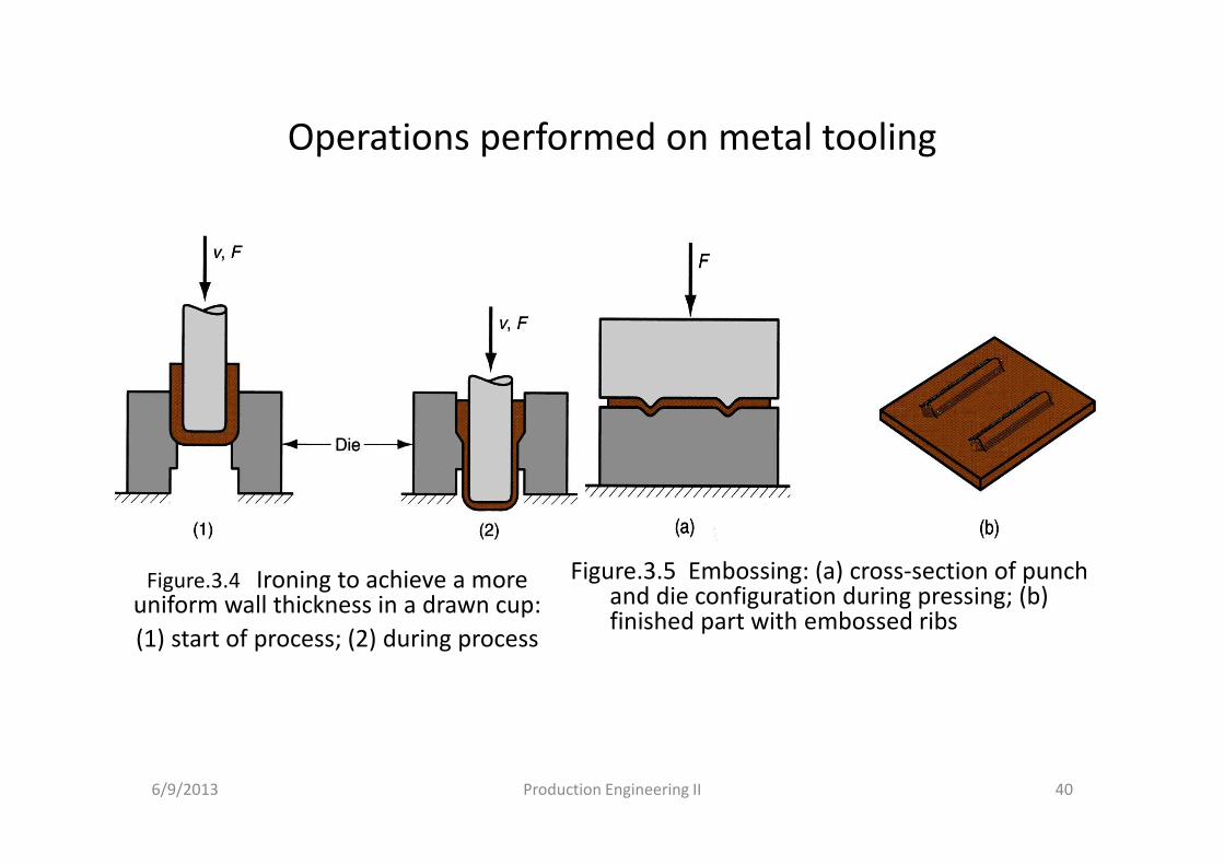
Operations performed on metal tooling
Figure.3.5 Embossing: (a) cross-section of punch and die configuration during pressing; (b) finished part with embossed ribs
6/9/2013 Production Engineering II 40
Figure.3.4 Ironing to achieve a more uniform wall thickness in a drawn cup:
(1) start of process; (2) during process
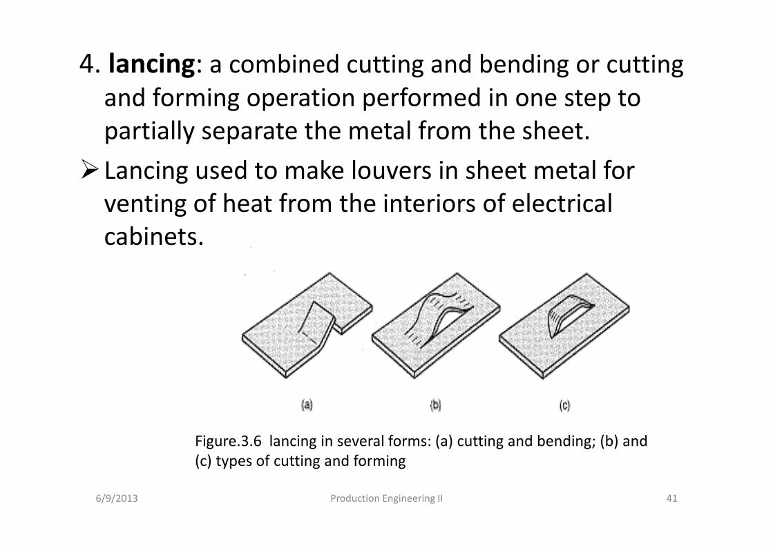
4. lancing: a combined cutting and bending or cutting
and forming operation performed in one step to
partially separate the metal from the sheet.
�Lancing used to make louvers in sheet metal for
venting of heat from the interiors of electrical
cabinets.
6/9/2013 Production Engineering II 41
Figure.3.6 lancing in several forms: (a) cutting and bending; (b) and
(c) types of cutting and forming
b. Rubber forming processThe operations performed on conventional presses and the
tooling are flexible element (made of rubber or similar materials) to effect the forming operation.
1. Guerin process: uses a thick rubber pad (other flexible material) to form sheet metal over a positive form block.
Advantage of Guerin process
• low cost of tooling
• form block can be made of wood, plastic, or other materials that are easy to shape
• The rubber pad can be used with different from blocks.
• Process attractive in small quantity production
e.g. aircraft industry
6/9/2013 Production Engineering II 42
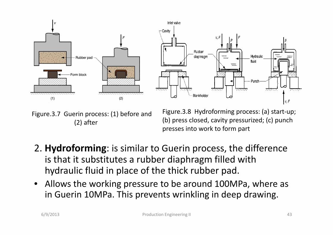
2. Hydroforming: is similar to Guerin process, the difference is that it substitutes a rubber diaphragm filled with hydraulic fluid in place of the thick rubber pad.
• Allows the working pressure to be around 100MPa, where as in Guerin 10MPa. This prevents wrinkling in deep drawing.
6/9/2013 Production Engineering II 43
Figure.3.7 Guerin process: (1) before and
(2) after
Figure.3.8 Hydroforming process: (a) start-up;
(b) press closed, cavity pressurized; (c) punch
presses into work to form part
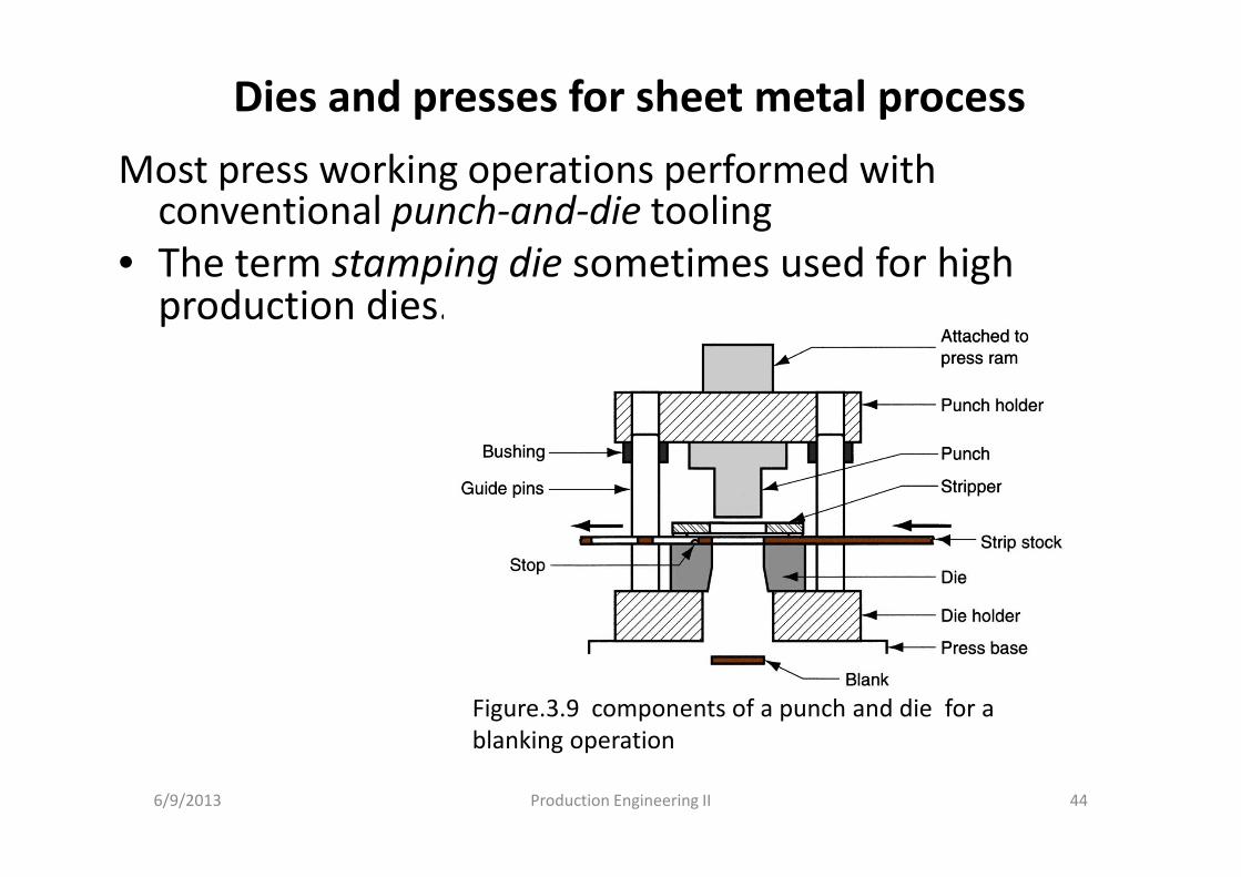
Dies and presses for sheet metal process
Most press working operations performed with conventional punch-and-die tooling
• The term stamping die sometimes used for high production dies.
6/9/2013 Production Engineering II 44
Figure.3.9 components of a punch and die for a
blanking operation
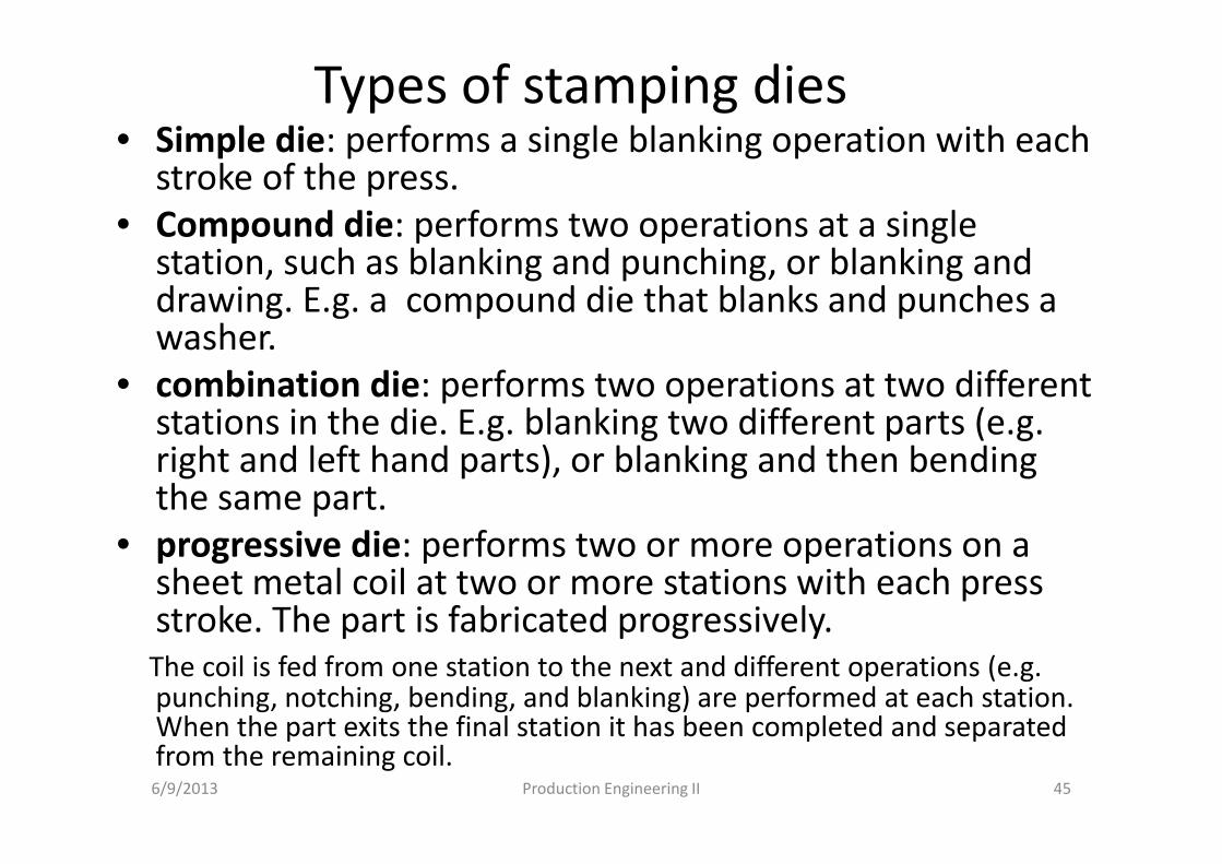
Types of stamping dies• Simple die: performs a single blanking operation with each
stroke of the press.
• Compound die: performs two operations at a single station, such as blanking and punching, or blanking and drawing. E.g. a compound die that blanks and punches a washer.
• combination die: performs two operations at two different stations in the die. E.g. blanking two different parts (e.g. right and left hand parts), or blanking and then bending the same part.
• progressive die: performs two or more operations on a sheet metal coil at two or more stations with each press stroke. The part is fabricated progressively.
The coil is fed from one station to the next and different operations (e.g. punching, notching, bending, and blanking) are performed at each station. When the part exits the final station it has been completed and separated from the remaining coil.
6/9/2013 Production Engineering II 45
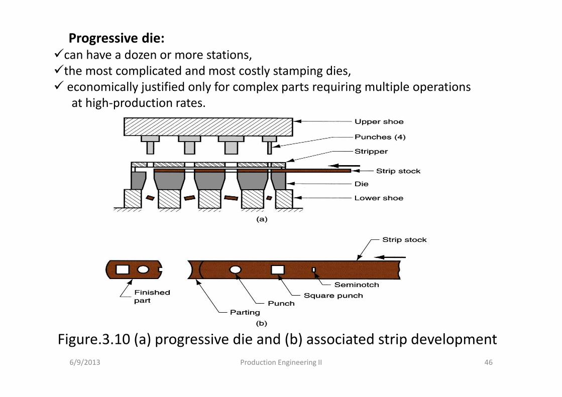
Figure.3.10 (a) progressive die and (b) associated strip development
6/9/2013 Production Engineering II 46
Progressive die:
�can have a dozen or more stations,
�the most complicated and most costly stamping dies,
� economically justified only for complex parts requiring multiple operations
at high-production rates.
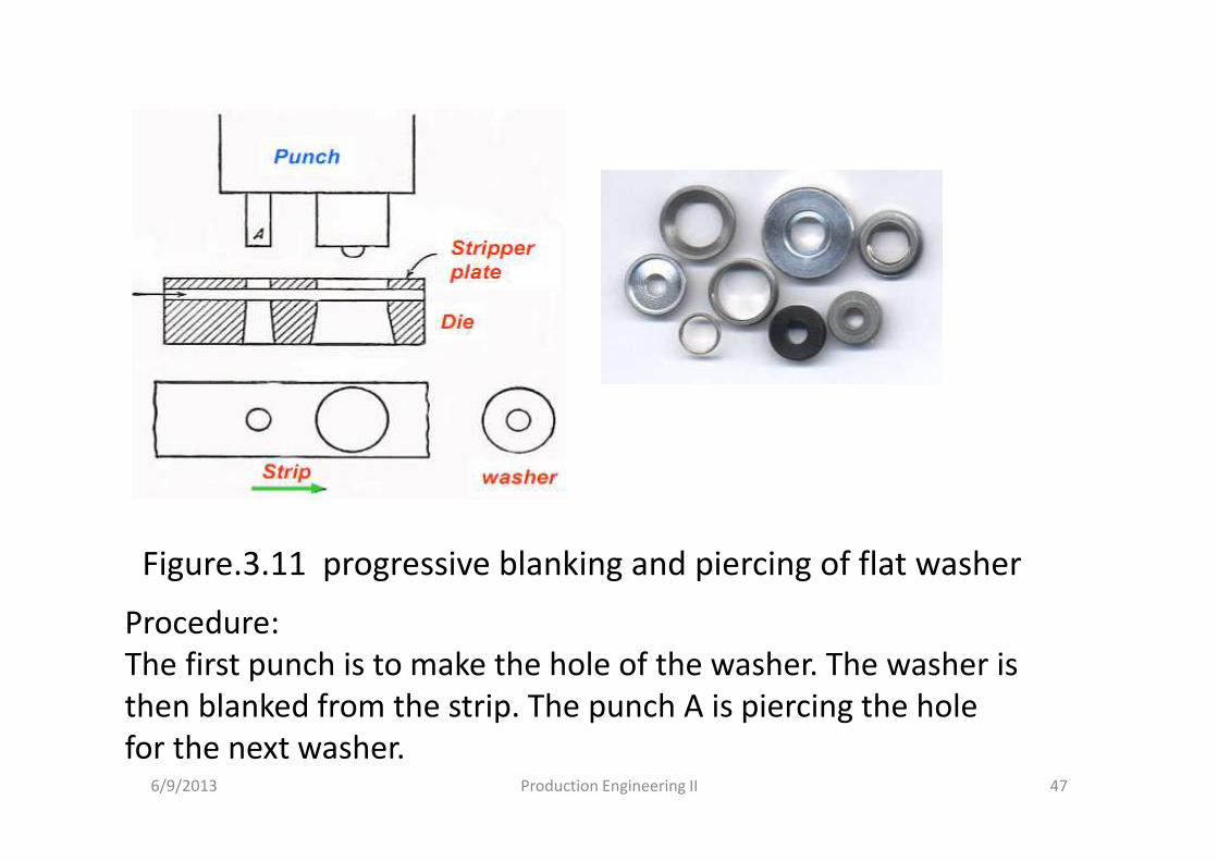
Figure.3.11 progressive blanking and piercing of flat washer
6/9/2013 Production Engineering II 47
Procedure:
The first punch is to make the hole of the washer. The washer is
then blanked from the strip. The punch A is piercing the hole
for the next washer.
Presses • A press used for sheet metal working is a machine
tool with a stationary bed and a powered ram that can be driven toward and away from the bed to perform various cutting and forming operations.
• The relative positions of the bed and ram are established by the frame, and the ram is driven by mechanical or hydraulic power.
• The capacity of a press is its ability to deliver the required force and energy to accomplish the stamping operation.
• The power system refers to whether mechanical or hydraulic power is used and the type of drive used to transmit the power to the ram.
6/9/2013 Production Engineering II 48
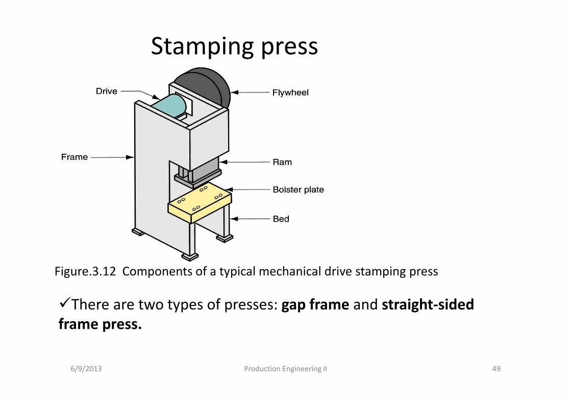
Stamping press
Figure.3.12 Components of a typical mechanical drive stamping press
6/9/2013 Production Engineering II 49
�There are two types of presses: gap frame and straight-sided
frame press.
Types of stamping press framei. Gap frame presses:
• has the general configuration of the letter C and is often called C-frame.
• Provide good access to the die, and they are usually open in the back to permit convenient ejection of stampings or scrap.
• Types of gap frame press: (a) solid gap frame, (b) adjustable bed, (c) open back inclinable, (d) press brake, and (e) turret press.
� Solid gap frame- the frame is rigid or one piece.
� Adjustable bed- has an adjustable bed to accommodate various die sizes.
� Open back inclinable- the frame can be tilted to various angles.
� Press brake- has a very wide bed, allows a number of separate dies to be set in the bed.
� Turret press- suited to situations in which a sequence of punching, notching, and related cutting operations.
6/9/2013 Production Engineering II 50
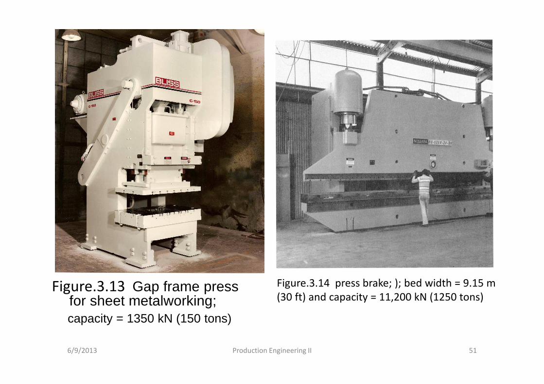
Figure.3.13 Gap frame press for sheet metalworking; capacity = 1350 kN (150 tons)
6/9/2013 Production Engineering II 51
Figure.3.14 press brake; ); bed width = 9.15 m
(30 ft) and capacity = 11,200 kN (1250 tons)
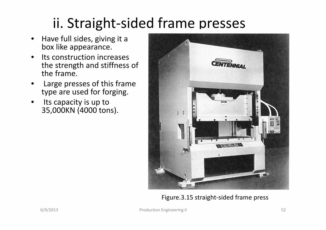
ii. Straight-sided frame presses• Have full sides, giving it a
box like appearance.
• Its construction increases the strength and stiffness of the frame.
• Large presses of this frame type are used for forging.
• Its capacity is up to 35,000KN (4000 tons).
6/9/2013 Production Engineering II 52
Figure.3.15 straight-sided frame press
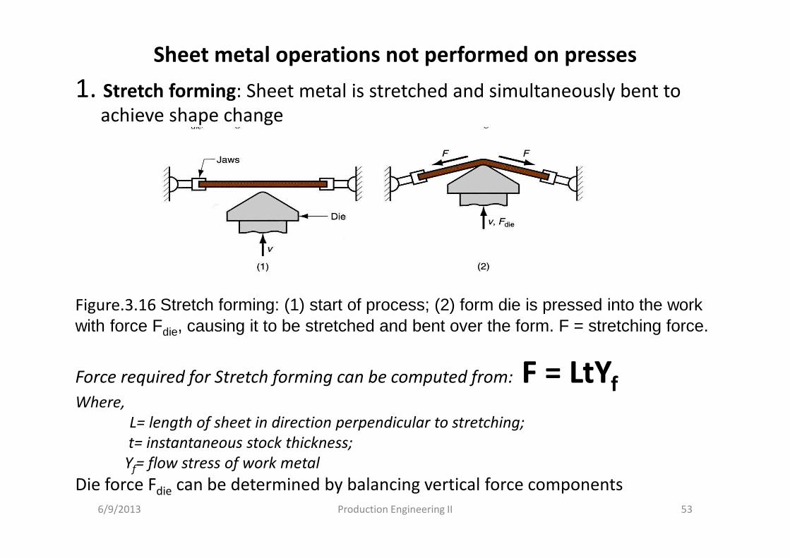
Sheet metal operations not performed on presses
1. Stretch forming: Sheet metal is stretched and simultaneously bent to
achieve shape change
6/9/2013 Production Engineering II 53
Figure.3.16 Stretch forming: (1) start of process; (2) form die is pressed into the work with force Fdie, causing it to be stretched and bent over the form. F = stretching force.
Force required for Stretch forming can be computed from: F = LtYfWhere,
L= length of sheet in direction perpendicular to stretching;
t= instantaneous stock thickness;
Yf= flow stress of work metal
Die force Fdie can be determined by balancing vertical force components
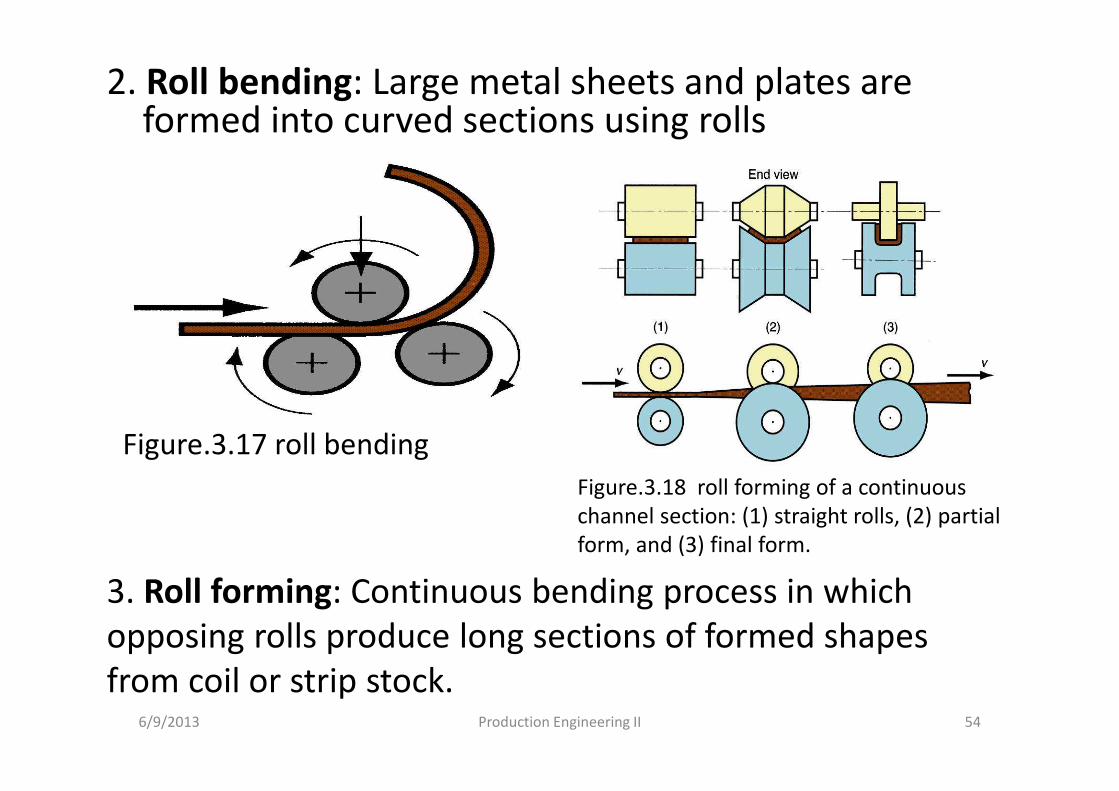
2. Roll bending: Large metal sheets and plates are formed into curved sections using rolls
6/9/2013 Production Engineering II 54
Figure.3.17 roll bending
Figure.3.18 roll forming of a continuous
channel section: (1) straight rolls, (2) partial
form, and (3) final form.
3. Roll forming: Continuous bending process in which
opposing rolls produce long sections of formed shapes
from coil or strip stock.
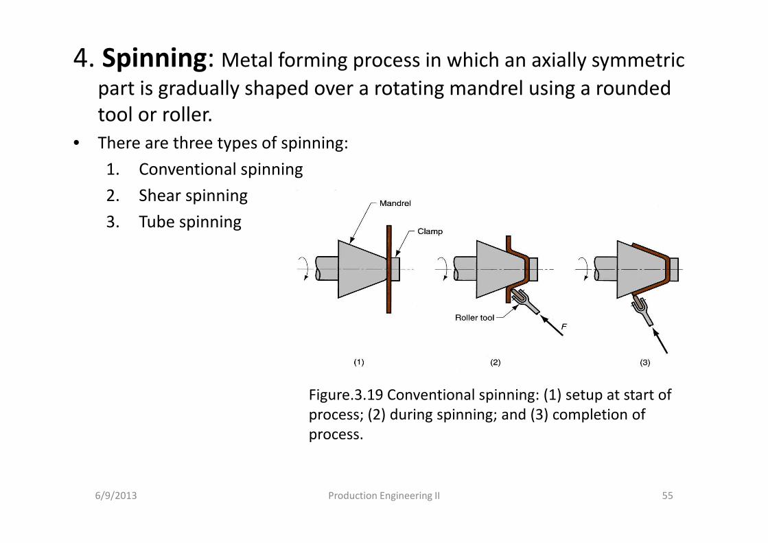
4. Spinning: Metal forming process in which an axially symmetric
part is gradually shaped over a rotating mandrel using a rounded
tool or roller.
• There are three types of spinning:
1. Conventional spinning
2. Shear spinning
3. Tube spinning
6/9/2013 Production Engineering II 55
Figure.3.19 Conventional spinning: (1) setup at start of
process; (2) during spinning; and (3) completion of
process.
Bending of tube stock• Is more difficult than sheet stock because a tube tends
to collapse and fold when attempts are made to bend it. Special flexible mandrels are usually inserted into the tube prior to bending to support the walls during the operation.
Terms in tube bending:
� the radius of the bend is defined with respect to the centerline of the tube.
�The minimum bend radius R that the tube can be bend is about 1.5 times the diameter when mandrel is used. If mandrel is not used it becomes 3 times the diameter.
6/9/2013 Production Engineering II 56
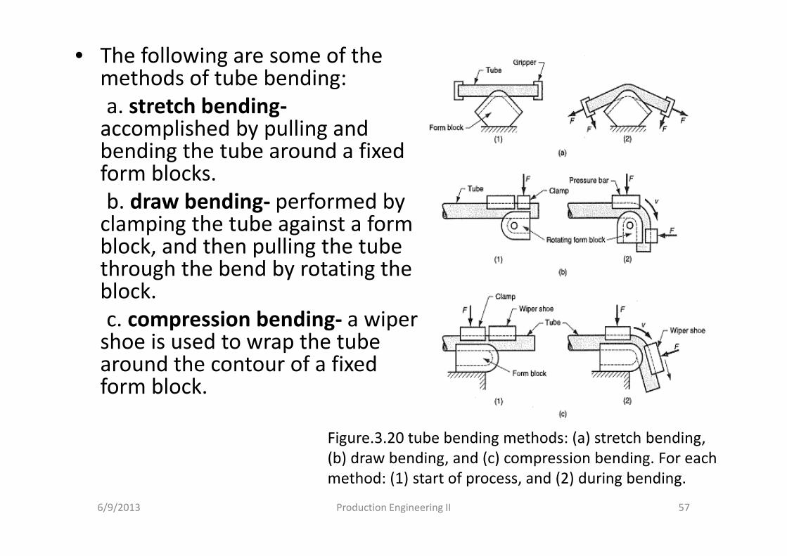
• The following are some of the methods of tube bending:
a. stretch bending-accomplished by pulling and bending the tube around a fixed form blocks.
b. draw bending- performed by clamping the tube against a form block, and then pulling the tube through the bend by rotating the block.
c. compression bending- a wiper shoe is used to wrap the tube around the contour of a fixed form block.
6/9/2013 Production Engineering II 57
Figure.3.20 tube bending methods: (a) stretch bending,
(b) draw bending, and (c) compression bending. For each
method: (1) start of process, and (2) during bending.