lt valve technical manual - hps-rental.de · api flanged, tool joint, ... greaseal™ plug for full...
TRANSCRIPT
Revision D April 03, 2014
LT VALVE TECHNICAL MANUAL
MSI is a division of Dixie Iron Works, Ltd. 300 West Main St.
Alice, Texas 78332 Phone: 1-800-242-0059
Phone: 1-361-664-6597 Fax: 1-361-664-4840
Email: [email protected]
MSI LT VALVE TECHNICAL MANUAL
Revision D April 03, 2014 2
TABLE OF CONTENTS
1.0 FEATURES ............................................................................................................. 3
1.1 SAFE-TAP™ GREASE FITTING ............................................................... 4
1.2 GREASEAL™ PLUG ....................................................................................... 5
2.0 EXPLODED VIEW .............................................................................................. 6
2.1 PARTS LIST ...................................................................................................... 7
3.0 ASSEMBLY PROCEDURE – UNISERT™ TYPE ..................................... 8
3.1 ASSEMBLY PROCEDURE – UNISERT™ TYPE (TEXT) .............. 19
3.2 ASSEMBLY PROCEDURE – SPLIT INSERT TYPE ....................... 21
3.3 ASSEMBLY PROCEDURE – SPLIT INSERT TYPE (TEXT) ...... 31
4.0 EXPLODED VIEW (5 INCH ) ..................................................................... 33
4.1 PARTS LIST .................................................................................................... 34
5.0 ASSEMBLY PROCEDURE – UNISERT™ TYPE (5 INCH) ............ 35
5.1 ASSEMBLY PROCEDURE – UNISERT™ TYPE (5 INCH) (TEXT) ....................................................................................................................... 44
5.2 ASSEMBLY PROCEDURE –SPLIT INSERT TYPE (5 INCH) ... 46
5.3 ASSEMBLY PROCEDURE –SPLIT INSERT TYPE (5 INCH) (TEXT) ....................................................................................................................... 55
6.0 DISASSEMBLY PROCEDURE ..................................................................... 57
7.0 MAINTENANCE ................................................................................................. 58
8.0 REPAIR AND INSPECTION ........................................................................ 59
8.1 DISASSEMBLY TIPS .................................................................................. 61
8.2 SANDING TIPS ............................................................................................ 62
8.3 ASSEMBLY TIPS .......................................................................................... 63
9.0 STORAGE ............................................................................................................. 64
9.1 SHELF LIFE .................................................................................................... 65
10.0 ACCESSORIES ................................................................................................ 66
10.1 GREASES ....................................................................................................... 67
10.2 GREASE REQUIREMENTS .................................................................... 68
10.3 ACTUATORS ................................................................................................ 69
10.4 RUBBER PRODUCTS ............................................................................... 70
MSI LT VALVE TECHNICAL MANUAL
Revision D April 03, 2014 3
1.0 FEATURES
The MSI LT Plug Valve is a lubricated, tapered pocket, quarter-turn plug valve for rapid full open or close operation. The valve cavity is tapered to ensure uniform
seating of the sealing inserts, providing a reliable seal at the full range of pressures. The MSI LT Plug Valve and replacement parts are engineered to provide low
operating toque and resistance to the toughest abrasive and corrosive conditions.
MSI offers more end connection choices than any other plug valve manufacturer in the industry. Connection types such as Hammer Unions, Line Pipe,
API Flanged, Tool Joint, Clamp Hub, and our own metal-to-metal WingSeal (WS20 and WS30) are just a few of the available choices. All sizes of MSI valves can be
outfitted with your choice of end connections or combinations to suit your specific application. Custom end-to-end lengths are also available on some valves.
Compact Design
Lightweight
Longer lasting internals
Ease of repair
Interchangeability
SafeTap™ grease fitting
UNIsert™ integral insert
GreaSeal™ plug for full 360° greasing
Widest range of end connections in the industry
o Hammer union (all sizes of 602, 1002, 1502, 2002, 2202)
o API Flange & Studded (all sizes and working pressures)
o WingSeal 20 (2.00”ID) & 30 (3.00”ID) *metal-to-metal
o Clamp Hub (all sizes such as B20, GR14, GR31, plus API clamp hubs)
o Threaded Ends (all sizes of Line Pipe, EU, NU, and premium threads)
o Tool Joint (All sizes of IF and ACME unions)
MSI LT VALVE TECHNICAL MANUAL
Revision D April 03, 2014 4
1.1 SAFETAP™ GREASE FITTING
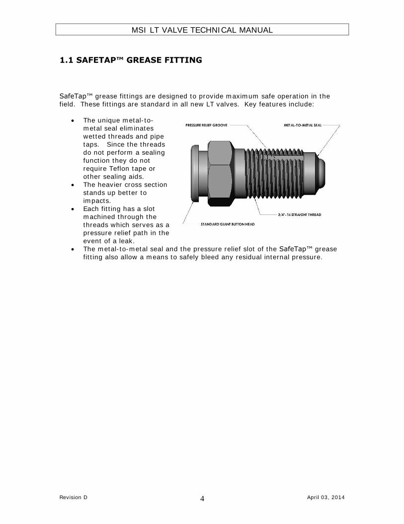
SafeTap™ grease fittings are designed to provide maximum safe operation in the field. These fittings are standard in all new LT valves. Key features include:
The unique metal-to-metal seal eliminates
wetted threads and pipe taps. Since the threads
do not perform a sealing function they do not
require Teflon tape or other sealing aids.
The heavier cross section
stands up better to impacts.
Each fitting has a slot machined through the
threads which serves as a pressure relief path in the
event of a leak. The metal-to-metal seal and the pressure relief slot of the SafeTap™ grease
fitting also allow a means to safely bleed any residual internal pressure.

MSI LT VALVE TECHNICAL MANUAL
Revision D April 03, 2014 5
1.2 GREASEAL™ PLUG
The patented GreaSeal™ plug is designed to provide maximum lubrication in the
harshest field conditions. Key features include:
The only plug that
allows greasing in the
opened or closed position while in
service. Dual 360°grease
channels. Forces grease into 360°
of the seal area when closed.
Allows for complete distribution of lubricant
immediately prior to opening a valve when
exposure to high
temperatures and well fluids may have
compromised the existing grease.
Greasing in the closed position can stop or
significantly slow leaks in valves with worn or
damaged parts.
Grease fitting installs from the bottom of the
plug for added protection from
impacts.

MSI LT VALVE TECHNICAL MANUAL
Revision D April 03, 2014 6
2.0 EXPLODED VIEW
MSI LT VALVE TECHNICAL MANUAL
Revision D April 03, 2014 7
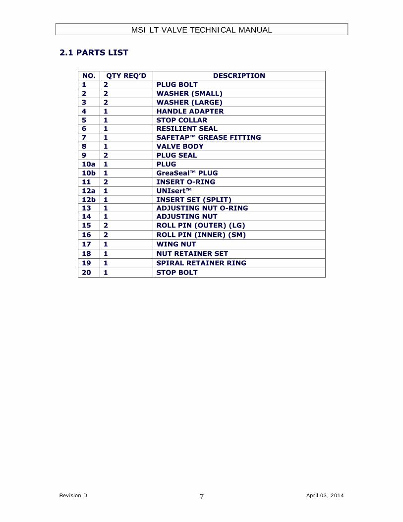
2.1 PARTS LIST
NO. QTY REQ’D DESCRIPTION
1 2 PLUG BOLT
2 2 WASHER (SMALL)
3 2 WASHER (LARGE)
4 1 HANDLE ADAPTER
5 1 STOP COLLAR
6 1 RESILIENT SEAL
7 1 SAFETAP™ GREASE FITTING
8 1 VALVE BODY
9 2 PLUG SEAL
10a 1 PLUG
10b 1 GreaSeal™ PLUG
11 2 INSERT O-RING
12a 1 UNIsert™
12b 1 INSERT SET (SPLIT)
13 1 ADJUSTING NUT O-RING
14 1 ADJUSTING NUT
15 2 ROLL PIN (OUTER) (LG)
16 2 ROLL PIN (INNER) (SM)
17 1 WING NUT
18 1 NUT RETAINER SET
19 1 SPIRAL RETAINER RING
20 1 STOP BOLT

MSI LT VALVE TECHNICAL MANUAL
Revision D April 03, 2014 8
3.0 ASSEMBLY PROCEDURE – UNISERT™ TYPE NOTE: It is imperative that the workstation being used to assemble the
valve be clean and free of anything that could possibly contaminate the grease such as metal shavings, dirt, rust, old paint, etc. Do not sand or
deburr near the workstation.
o Check surfaces around the
valve bore inside the valve pocket for sharp edges
that could cause cutting of the insert o-rings. Then
screw the clean adjusting
nut (14) all the way into the valve body to make
sure the threads are not damaged.
o After inspection, remove
the adjusting nut (14), grease the sealing groove
and install the adjusting nut o ring (13) in the
groove.
o Check the roll pins (15 & 16) in the valve body by
gently sliding a UNIsert™ (12) into the valve. The
UNIsert™ (12) should
move freely up and down the length of the roll pin
slots without interference.

MSI LT VALVE TECHNICAL MANUAL
Revision D April 03, 2014 9
o Apply a thin film of
lubricant to the recess in the valve body (8) and
install the plug seal (9) with the metal back
towards the recess facing away from the pressure.
o Apply a thin film of
lubricant to the recess in
the adjusting nut (14) and install the plug seal
(9) with the metal back towards the recess facing
away from the pressure.
o Check the plug (10) outside diameter for
surface defects such as
scratches, dings, nicks, or sharp edges that could
affect the sealing area. See 8.2 SANDING TIPS
for repair.

MSI LT VALVE TECHNICAL MANUAL
Revision D April 03, 2014 10
o Check the surface finish of
the UNIsert™ (12) making sure it does not
have any scratches, dings, nicks or sharp edges that
could also affect the sealing area. See 8.2
SANDING TIPS for repair.
o Inspect the adjusting nut
o-ring (13) for any
possible non-conformity.
o Pack the adjusting nut (14) plug seal (9) with
valve grease.
MSI LT VALVE TECHNICAL MANUAL
Revision D April 03, 2014 11
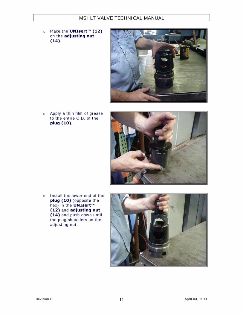
o Place the UNIsert™ (12)
on the adjusting nut (14).
o Apply a thin film of grease
to the entire O.D. of the
plug (10).
o Install the lower end of the plug (10) (opposite the
hex) in the UNIsert™
(12) and adjusting nut (14) and push down until
the plug shoulders on the adjusting nut.

MSI LT VALVE TECHNICAL MANUAL
Revision D April 03, 2014 12
o Place the insert o-rings
(11) in to the grooves on the UNIsert™ (12) and
pack with grease to retain the rings and thoroughly
grease the sealing surfaces.
o Secure the plug (10) to
the adjusting nut (14) with the plug bolt (1) and
two washers (2 & 3).
o Lubricate the valve pocket
with valve grease.

MSI LT VALVE TECHNICAL MANUAL
Revision D April 03, 2014 13
o Apply thread compound
(Never-Seez) to the adjusting nut threads and
adjusting nut sealing surfaces.
o Support the valve so that
the plug (10) hex can
pass through unobstructed.
o Install the plug (10),
UNIsert™ (12) and
adjusting nut (14) assembly into the valve
body.

MSI LT VALVE TECHNICAL MANUAL
Revision D April 03, 2014 14
o Screw in the adjusting nut
until proper alignment is obtained between the
valve bore, the UNIsert™ and plug. Do not tighten
beyond proper alignment as actuating an over
tightened valve could damage internal parts. If
sight through the bore is
not possible, then screw in the adjusting nut until ½
or no thread is visible.
o Apply thread compound
(never Seez) to the
threads on the SafeTap™ grease fitting (7).
NOTE: Do not use Teflon
tape on the grease fitting.
o Install SafeTap™ grease fitting (7) and torque to
80 ft-lbs.

MSI LT VALVE TECHNICAL MANUAL
Revision D April 03, 2014 15
o Place spiral retainer ring
(19) on male end (if required).
o Then place wing nut (17) on male end and install the
nut retainer set (18) (if
required).
o Secure the retainers with spiral retainer ring (if
required)
MSI LT VALVE TECHNICAL MANUAL
Revision D April 03, 2014 16
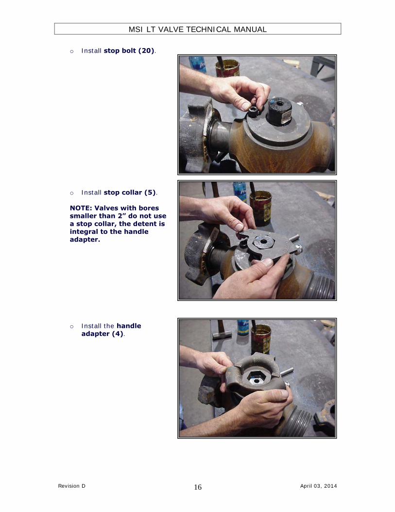
o Install stop bolt (20).
o Install stop collar (5).
NOTE: Valves with bores smaller than 2” do not use
a stop collar, the detent is integral to the handle
adapter.
o Install the handle adapter (4).

MSI LT VALVE TECHNICAL MANUAL
Revision D April 03, 2014 17
o Secure handle adapter (4) with the plug bolt (1) and washers (2 & 3).
o Remove excess grease from valve bore.
o Inspect plug alignment and adjust as necessary with
adjusting nut (14).
MSI LT VALVE TECHNICAL MANUAL
Revision D April 03, 2014 18
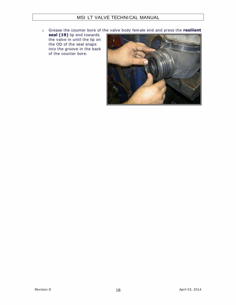
o Grease the counter bore of the valve body female end and press the resilient
seal (19) lip end towards the valve in until the lip on
the OD of the seal snaps into the groove in the back
of the counter bore.

MSI LT VALVE TECHNICAL MANUAL
Revision D April 03, 2014 19
3.1 ASSEMBLY PROCEDURE – UNISERT™ TYPE (TEXT)
NOTE: It is imperative that the workstation being used to assemble the valve be clean and free of anything that could possibly contaminate the
grease such as metal shavings, dirt, rust, old paint, etc. Do not sand or deburr near the workstation.
1. Check surfaces around the valve bore inside the valve pocket for sharp edges
that could cause cutting of the insert o-rings. Then screw the clean adjusting nut (14) all the way into the valve body to make sure the threads
are not damaged. 2. After inspection, remove the adjusting nut (14), grease the sealing groove
and install the adjusting nut o ring (13) in the groove.
3. Check the roll pins (15 & 16) in the valve body by gently sliding a UNIsert™ (12) into the valve. The UNIsert™ (12) should move freely up
and down the length of the roll pin slots without interference.
4. Apply a thin film of lubricant to the recess in the valve body (8) and install
the plug seal (9) with the metal back towards the recess facing away from the pressure.
5. Apply a thin film of lubricant to the recess in the adjusting nut (14) and
install the plug seal (9) with the metal back towards the recess facing away from the pressure.
6. Check the plug (10) outside diameter for surface defects such as scratches, dings, nicks, or sharp edges that could affect the sealing area. See 8.2
SANDING TIPS for repair.
7. Check the surface finish of the UNIsert™ (12) making sure it does not have any scratches, dings, nicks or sharp edges that could also affect the sealing
area. See 8.2 SANDING TIPS for repair.
8. Inspect the adjusting nut o-ring (13) for any possible non-conformity.
9. Pack the adjusting nut (14) plug seal (9) with valve grease.
10. Place the UNIsert™ (12) on the adjusting nut (14).
11. Apply a thin film of grease to the entire O.D. of the plug (10).
12. Install the lower end of the plug (10) (opposite the hex/keyway) in the
UNIsert™ (12) and adjusting nut (14) and push down until the plug
shoulders on the adjusting nut.
13. Place the insert o-rings (11) in to the grooves on the UNIsert™ (12) and pack with grease to thoroughly grease the sealing surfaces.
14. Secure the plug (10) to the adjusting nut (14) with the plug bolt (1) and
two washers (2 & 3).

MSI LT VALVE TECHNICAL MANUAL
Revision D April 03, 2014 20
15. Lubricate the valve pocket with valve grease.
16. Apply thread compound (Never-Seez) to the adjusting nut threads and adjusting nut sealing surfaces.
17. Support the valve so that the plug (10) hex can pass through unobstructed.
18. Install the plug (10), UNIsert™ (12) and adjusting nut (14) assembly
into the valve body.
19. Screw in the adjusting nut until proper alignment is obtained between the
valve bore, the UNIsert™ and plug. Do not tighten beyond proper alignment as actuating an over tightened valve could damage internal parts. If sight
through the bore is not possible, then screw in the adjusting nut until ½ or no thread is visible.
20. Apply thread compound (Never-Seez) to the threads on the SafeTap™
grease fitting (7). NOTE: Do not use Teflon tape on the grease fitting.
21. Install SafeTap™ grease fitting (7) and torque to 80 ft-lbs.
22. Place spiral retainer ring (19) on male end (if required).
23. Then place wing nut (17) on male end and install the nut retainer set
(18) (if required).
24. Secure the retainers with spiral retainer ring (if required).
25. Install stop bolt (20).
26. Install stop collar (5). NOTE: Valves with bores smaller than 2” do not
use a stop collar, the detent is integral to the handle adapter.
27. Install the handle adapter (4).
28. Secure handle adapter (4) with the plug bolt (1) and washers (2 & 3).
29. Remove excess grease from valve bore.
30. Inspect plug alignment and adjust as necessary with adjusting nut (14).
31. Grease the counter bore of the valve body female end and press the resilient
seal (19) lip end towards the valve in until the lip on the OD of the seal snaps into the groove in the back of the counter bore.

MSI LT VALVE TECHNICAL MANUAL
Revision D April 03, 2014 21
3.2 ASSEMBLY PROCEDURE – SPLIT INSERT TYPE NOTE: It is imperative that the workstation being used to assemble the
valve be clean and free of anything that could possibly contaminate the grease such as metal shavings, dirt, rust, old paint, etc. Do not sand or
deburr near the workstation.
o Check surfaces around the
valve bore inside the valve pocket for sharp edges that
could cause cutting of the insert o-rings. Then screw
the clean adjusting nut
(14) all the way into the valve body to make sure
the threads are not damaged.
o After inspection, remove
the adjusting nut (14), grease the sealing groove
and install the adjusting nut o ring (13) in the
groove.
o Check the roll pins (15 & 16) in the valve body by
gently sliding a set of inserts (12) into the
valve. The inserts (12)
should move freely up and down the length of the roll
pin slots without interference.
MSI LT VALVE TECHNICAL MANUAL
Revision D April 03, 2014 22
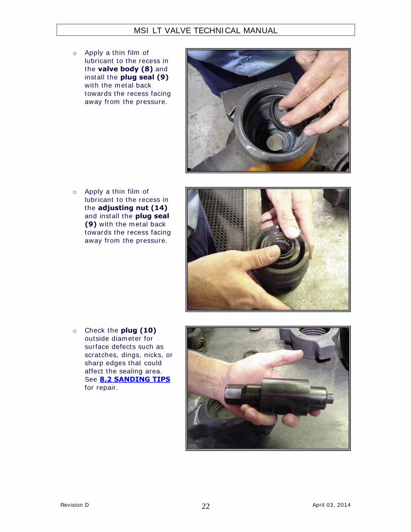
o Apply a thin film of
lubricant to the recess in the valve body (8) and
install the plug seal (9) with the metal back
towards the recess facing away from the pressure.
o Apply a thin film of
lubricant to the recess in
the adjusting nut (14) and install the plug seal
(9) with the metal back towards the recess facing
away from the pressure.
o Check the plug (10) outside diameter for
surface defects such as
scratches, dings, nicks, or sharp edges that could
affect the sealing area. See 8.2 SANDING TIPS
for repair.
MSI LT VALVE TECHNICAL MANUAL
Revision D April 03, 2014 23
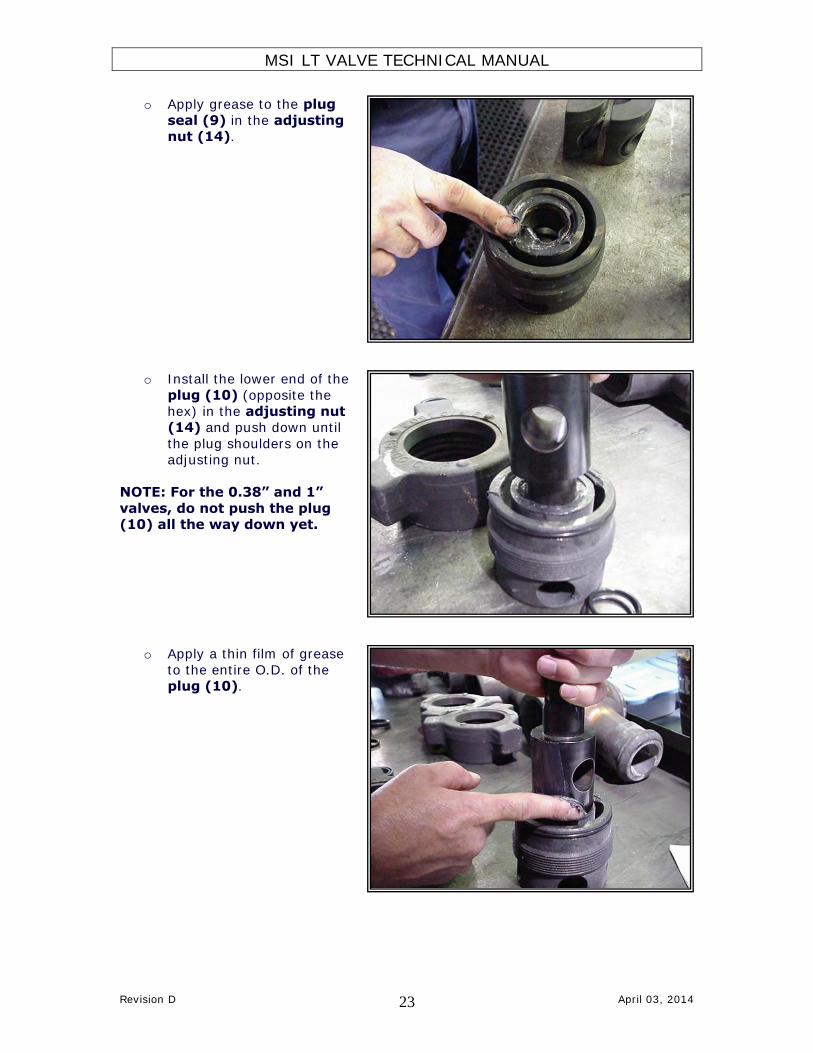
o Apply grease to the plug
seal (9) in the adjusting nut (14).
o Install the lower end of the
plug (10) (opposite the
hex) in the adjusting nut (14) and push down until
the plug shoulders on the adjusting nut.
NOTE: For the 0.38” and 1”
valves, do not push the plug (10) all the way down yet.
o Apply a thin film of grease to the entire O.D. of the
plug (10).

MSI LT VALVE TECHNICAL MANUAL
Revision D April 03, 2014 24
o Check the surface finish of
the inserts (12) making sure they do not have any
scratches, dings, nicks or sharp edges that could
affect the sealing area. See 8.2 SANDING TIPS
for repair.
o Inspect the insert o-rings
(11) for any possible non-
conformity.
o Place the inserts (12) around the plug (10).
NOTE: For the 0.38” and 1” valves, push the plug
(10) all the way down now.

MSI LT VALVE TECHNICAL MANUAL
Revision D April 03, 2014 25
o Install the insert o-rings
(11) into the insert (12) grooves and coat with
grease to retain the rings.
o Make sure the entire
sealing surface is
thoroughly greased.
o Secure the plug to the adjusting nut with the plug
bolt (1) and washers (2
& 3).

MSI LT VALVE TECHNICAL MANUAL
Revision D April 03, 2014 26
o Lubricate the valve pocket
with valve grease.
o Apply thread compound (Never-Seez) to the
adjusting nut threads and adjusting nut sealing
surfaces.
o Install the plug (10),
inserts (12) and adjusting nut (14)
assembly into the valve body.

MSI LT VALVE TECHNICAL MANUAL
Revision D April 03, 2014 27
o Support the valve so that
the plug (10) hex can pass through unobstructed.
o Tighten the adjusting nut
(14) until snug and back
off ¼ turn from snug position.
o Apply thread compound (Never Seez) to the
threads on the SafeTap™
grease fitting (7). Install grease fitting and torque to
80 ft-lbs.
NOTE: Do not use Teflon tape on the grease
fitting.

MSI LT VALVE TECHNICAL MANUAL
Revision D April 03, 2014 28
o Place spiral retainer ring
(19) on male end (if required).
o Then place wing nut (17) on male end and install the
nut retainer set (18) (if
required).
o Secure the retainers with spiral retainer ring (if
required)
MSI LT VALVE TECHNICAL MANUAL
Revision D April 03, 2014 29
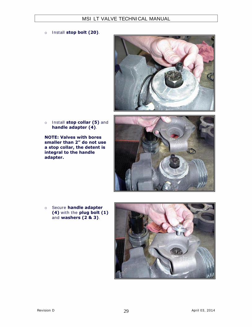
o Install stop bolt (20).
o Install stop collar (5) and
handle adapter (4).
NOTE: Valves with bores
smaller than 2” do not use a stop collar, the detent is
integral to the handle
adapter.
o Secure handle adapter (4) with the plug bolt (1)
and washers (2 & 3).
MSI LT VALVE TECHNICAL MANUAL
Revision D April 03, 2014 30
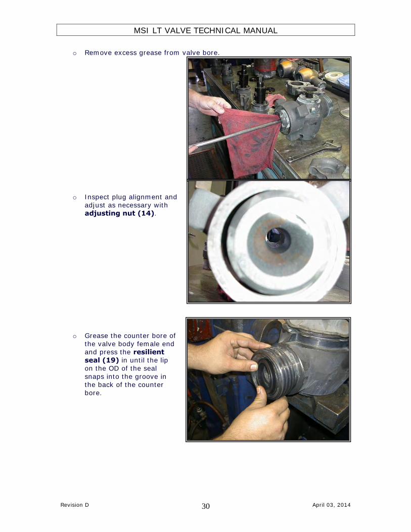
o Remove excess grease from valve bore.
o Inspect plug alignment and
adjust as necessary with adjusting nut (14).
o Grease the counter bore of
the valve body female end and press the resilient
seal (19) in until the lip on the OD of the seal
snaps into the groove in the back of the counter
bore.

MSI LT VALVE TECHNICAL MANUAL
Revision D April 03, 2014 31
3.3 ASSEMBLY PROCEDURE – SPLIT INSERT TYPE (TEXT)
NOTE: It is imperative that the workstation being used to assemble the valve be clean and free of anything that could possibly contaminate the
grease such as metal shavings, dirt, rust, old paint, etc. Do not sand or deburr near the workstation.
1. Check surfaces around the valve bore inside the valve pocket for sharp edges
that could cause cutting of the insert o-rings. Then screw the clean
adjusting nut (14) all the way into the valve body to make sure the threads are not damaged.
2. After inspection, remove the adjusting nut (14), grease the sealing groove
and install the adjusting nut o ring (13) in the groove.
3. Check the roll pins (15 & 16) in the valve body by gently sliding a set of insert (12) into the valve. The inserts (12) should move freely up and
down the length of the roll pin slots without interference.
4. Apply a thin film of lubricant to the recess in the valve body (8) and install the plug seal (9) with the metal back towards the recess facing away from
the pressure.
5. Apply a thin film of lubricant to the recess in the adjusting nut (14) and
install the plug seal (9) with the metal back towards the recess facing away from the pressure.
6. Check the plug (10) outside diameter for surface defects such as scratches,
dings, nicks, or sharp edges that could affect the sealing area. See 8.2 SANDING TIPS for repair.
7. Apply grease to the plug seal (9) in the adjusting nut (14).
8. Install the lower end of the plug (10) (opposite the hex/keyway) in the adjusting nut (14) and push down until the plug shoulders on the adjusting
nut. NOTE: For the 0.38” and 1” valves, do not push the plug (10) all the way down yet.
9. Apply a thin film of grease to the entire O.D. of the plug (10).
10. Check the surface finish of the inserts (12) making sure they do not have any scratches, dings, nicks or sharp edges that could affect the sealing area.
See 8.2 SANDING TIPS for repair.
11. Inspect the insert o-rings (11) for any possible non-conformity.
12. Place the inserts (12) around the plug (10). NOTE: For the 0.38” and 1” valves, push the plug (10) all the way down now.
13. Install the insert o-rings (11) into the insert (12) grooves and coat with grease.
MSI LT VALVE TECHNICAL MANUAL
Revision D April 03, 2014 32
14. Make sure the entire sealing surface is thoroughly greased.
15. Secure the plug to the adjusting nut with the plug bolt (1) and washers (2
& 3).
16. Lubricate the valve pocket with valve grease.
17. Apply thread compound (Never-Seez) to the adjusting nut threads and adjusting nut sealing surfaces.
18. Install the plug (10), inserts (12) and adjusting nut (14) assembly into the valve body.
19. Support the valve so that the plug (10) hex can pass through unobstructed.
20. Tighten the adjusting nut (14) until snug and back off ¼ turn from snug
position.
21. Apply thread compound (Never Seez) to the threads on the SafeTap™ grease
fitting (7). Install grease fitting and torque to 80 ft-lbs. NOTE: Do not use Teflon tape on the grease fitting.
22. Place spiral retainer ring (19) on male end (if required).
23. Then place wing nut (17) on male end and install the nut retainer set
(18) (if required).
24. Secure the retainers with spiral retainer ring (if required)
25. Install stop bolt (20).
26. Install stop collar (5) and handle adapter (4). NOTE: Valves with bores
smaller than 2” do not use a stop collar, the detent is integral to the handle adapter.
27. Secure handle adapter (4) with the plug bolt (1) and washers (2 & 3).
28. Remove excess grease from valve bore.
29. Inspect plug alignment and adjust as necessary with adjusting nut (14).
30. Grease the counter bore of the valve body female end and press the resilient seal (19) in until the lip on the OD of the seal snaps into the groove in the
back of the counter bore.

MSI LT VALVE TECHNICAL MANUAL
Revision D April 03, 2014 33
4.0 EXPLODED VIEW (5” VALVE)
MSI LT VALVE TECHNICAL MANUAL
Revision D April 03, 2014 34
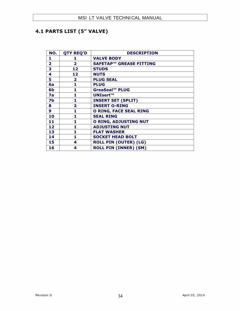
4.1 PARTS LIST (5” VALVE)
NO. QTY REQ’D DESCRIPTION
1 1 VALVE BODY
2 2 SAFETAP™ GREASE FITTING
3 12 STUDS
4 12 NUTS
5 2 PLUG SEAL
6a 1 PLUG
6b 1 GreaSeal™ PLUG
7a 1 UNIsert™
7b 1 INSERT SET (SPLIT)
8 2 INSERT O-RING
9 1 O RING, FACE SEAL RING
10 1 SEAL RING
11 1 O RING, ADJUSTING NUT
12 1 ADJUSTING NUT
13 1 FLAT WASHER
14 1 SOCKET HEAD BOLT
15 4 ROLL PIN (OUTER) (LG)
16 4 ROLL PIN (INNER) (SM)
MSI LT VALVE TECHNICAL MANUAL
Revision D April 03, 2014 35
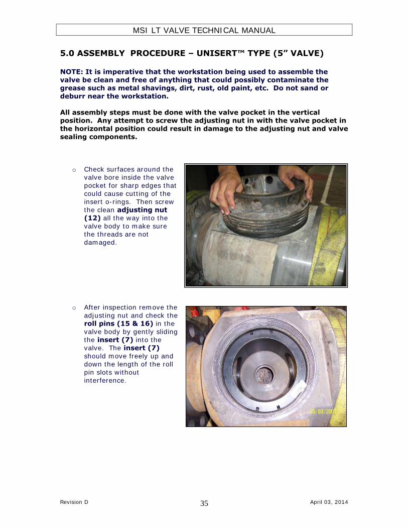
5.0 ASSEMBLY PROCEDURE – UNISERT™ TYPE (5” VALVE)
NOTE: It is imperative that the workstation being used to assemble the
valve be clean and free of anything that could possibly contaminate the grease such as metal shavings, dirt, rust, old paint, etc. Do not sand or
deburr near the workstation.
All assembly steps must be done with the valve pocket in the vertical position. Any attempt to screw the adjusting nut in with the valve pocket in
the horizontal position could result in damage to the adjusting nut and valve
sealing components.
o Check surfaces around the valve bore inside the valve
pocket for sharp edges that could cause cutting of the
insert o-rings. Then screw
the clean adjusting nut (12) all the way into the
valve body to make sure the threads are not
damaged.
o After inspection remove the
adjusting nut and check the roll pins (15 & 16) in the
valve body by gently sliding the insert (7) into the
valve. The insert (7)
should move freely up and down the length of the roll
pin slots without interference.

MSI LT VALVE TECHNICAL MANUAL
Revision D April 03, 2014 36
o Apply a thin film of
lubricant to the recess in the adjusting nut (12)
and install the plug seal (5) with the metal back
towards the recess facing away from the pressure.
o Apply grease to the plug
seal (5) in the adjusting
nut (12).
o Grease the sealing groove and install the adjusting
nut o ring (11) in the
groove.

MSI LT VALVE TECHNICAL MANUAL
Revision D April 03, 2014 37
o Apply a thin film of
lubricant to the pocket and the recess in the valve
body (1) and install the plug seal (5) with the
metal back towards the recess facing away from
the pressure.
o Check the plug (6)
outside diameter for
surface defects such as scratches, dings, nicks, or
sharp edges that could affect the sealing area.
See 8.2 SANDING TIPS for repair.
o Support the valve so that
the plug hex can pass
through unobstructed.
MSI LT VALVE TECHNICAL MANUAL
Revision D April 03, 2014 38
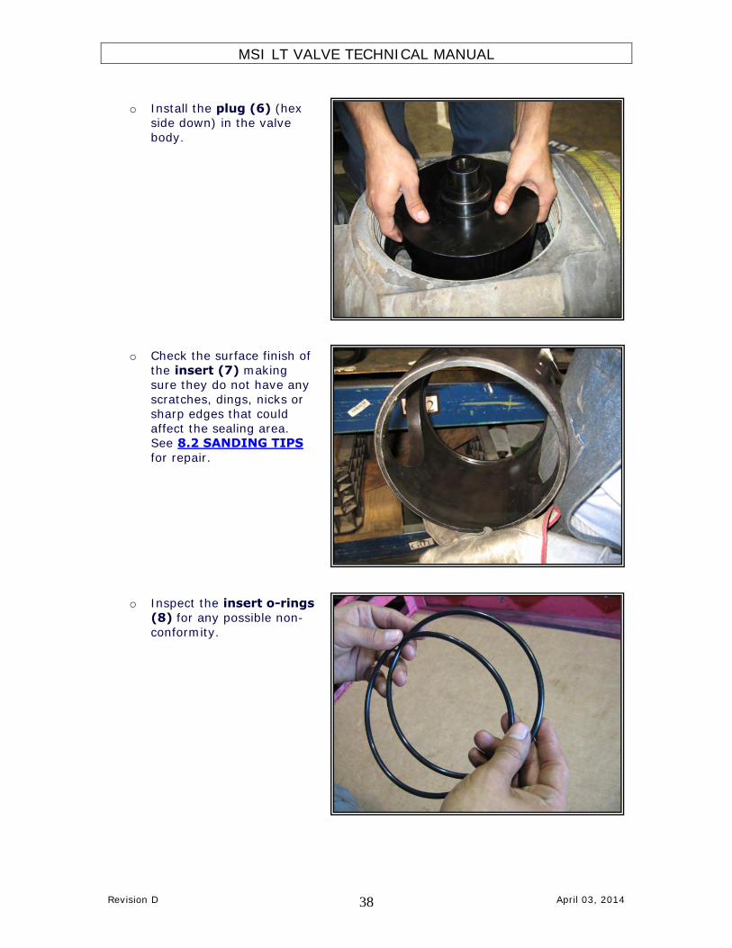
o Install the plug (6) (hex side down) in the valve
body.
o Check the surface finish of
the insert (7) making sure they do not have any
scratches, dings, nicks or sharp edges that could
affect the sealing area. See 8.2 SANDING TIPS
for repair.
o Inspect the insert o-rings
(8) for any possible non-
conformity.

MSI LT VALVE TECHNICAL MANUAL
Revision D April 03, 2014 39
o Install the insert o-rings (8) into the insert (7)
grooves and coat with grease to retain the rings.
o Make sure the entire sealing surface is
thoroughly greased.
o Apply a thin film of grease
to the entire I.D. of the insert (7).

MSI LT VALVE TECHNICAL MANUAL
Revision D April 03, 2014 40
o Place the insert (7) around the plug (6) in the valve
body making sure it slides into the roll pins.
o Apply thread compound (Never-Seez) to the
adjusting nut threads and adjusting nut sealing
surfaces.
o Grease the seal ring (10) groove and insert the o ring
(9) over it.

MSI LT VALVE TECHNICAL MANUAL
Revision D April 03, 2014 41
o Place the seal ring (10) on the top of the insert (7).
o Install the adjusting nut
(12) into the valve body and tighten until snug and back
off ¼ turn from the snug position.
o Apply thread compound
(Never Seez) grease to the
plug bolt (14) threads and tighten it with the allen
wrench on the adjusting nut side of the plug (6).

MSI LT VALVE TECHNICAL MANUAL
Revision D April 03, 2014 42
o Apply thread compound
(Never Seez) to the threads on the SafeTap™ grease
fitting (2). Install grease fitting and torque to 80 ft-
lbs.
NOTE: Do not use Teflon tape on the grease fitting.
o Remove excess grease from valve bore.
o Inspect plug alignment and
adjust as necessary with adjusting nut (12).

MSI LT VALVE TECHNICAL MANUAL
Revision D April 03, 2014 43
o Apply Removable
Threadlocker (blue) in the threads of the stud end and
screw the studs (3) until tight. Screw the nuts (4)
on the studs (3).
Note: Do not use High
Strength (red) Threadlocker.

MSI LT VALVE TECHNICAL MANUAL
Revision D April 03, 2014 44
5.1 ASSEMBLY PROCEDURE- UNISERT™ TYPE (5” VALVE)
(TEXT) NOTE: It is imperative that the workstation being used to assemble the
valve be clean and free of anything that could possibly contaminate the grease such as metal shavings, dirt, rust, old paint, etc. Do not sand or
deburr near the workstation.
All assembly steps must be done with the valve pocket in the vertical position. Any attempt to screw the adjusting nut in with the valve pocket in
the horizontal position could result in damage to the adjusting nut and valve
sealing components.
1. Check surfaces around the valve bore inside the valve pocket for sharp edges
that could cause cutting of the insert o-rings. Then screw the clean adjusting nut (12) all the way into the valve body to make sure the threads
are not damaged.
2. After inspection remove the adjusting nut and check the roll pins (15 & 16)
in the valve body by gently sliding the insert (7) into the valve. The insert (7) should move freely up and down the length of the roll pin slots without
interference.
3. Apply a thin film of lubricant to the recess in the adjusting nut (12) and install the plug seal (5) with the metal back towards the recess facing away
from the pressure.
4. Apply grease to the plug seal (5) in the adjusting nut (12).
5. Grease the sealing groove and install the adjusting nut o ring (11) in the
groove.
6. Apply a thin film of lubricant to the pocket and the recess in the valve body (1) and install the plug seal (5) with the metal back towards the recess
facing away from the pressure. 7.
8. Check the plug (6) outside diameter for surface defects such as scratches,
dings, nicks, or sharp edges that could affect the sealing area. See 8.2 SANDING TIPS for repair.
9. Support the valve body (1) so that the plug hex can pass through
unobstructed.
10. Install the plug (6) (hex side down) in the valve body (1).
11. Check the surface finish of the inserts (7) making sure they do not have any
scratches, dings, nicks or sharp edges that could affect the sealing area. See 8.2 SANDING TIPS for repair.
12. Inspect the insert o-rings (8) for any possible non-conformity.
13. Install the insert o-rings (8) into the insert (7) grooves and coat with grease to retain the rings.

MSI LT VALVE TECHNICAL MANUAL
Revision D April 03, 2014 45
14. Make sure the entire sealing surface is thoroughly greased.
15. Apply a thin film of grease to the entire I.D. of the insert (7).
16. Place the insert (7) around the plug (6) in the valve body (1) making sure
it slides into the roll pins.
17. Apply thread compound (Never-Seez) to the adjusting nut threads and adjusting nut sealing surfaces.
18. Grease the seal ring (10) groove and insert the o ring (9) over it.
19. Place the seal ring (10) on the top of the insert (7).
20. Install the adjusting nut (12) into the valve body (1) and tighten until snug and back off ¼ turn from the snug position.
21. Apply thread compound (Never Seez) grease to the plug bolt (14) threads
and tighten it with the allen wrench on the adjusting nut side of the plug (6).
22. Apply thread compound (Never Seez) to the threads on the SafeTap™
grease fitting (2). Install grease fittings and torque to 80 ft-lbs. NOTE: Do not use Teflon tape on the grease fitting.
23. Remove excess grease from valve bore.
24. Inspect plug alignment and adjust as necessary with adjusting nut (12).
25. Apply Removable Threadlocker (blue) in the threads of the stud end and
screw the studs (3) until tight. Screw the nuts (4) over the studs (3) Note: Do not use Red High Strength Threadlocker.

MSI LT VALVE TECHNICAL MANUAL
Revision D April 03, 2014 46
5.2 ASSEMBLY PROCEDURE- SPLIT INSERT TYPE (5” VALVE) NOTE: It is imperative that the workstation being used to assemble the
valve be clean and free of anything that could possibly contaminate the grease such as metal shavings, dirt, rust, old paint, etc. Do not sand or
deburr near the workstation.
All assembly steps must be done with the valve pocket in the vertical position. Any attempt to screw the adjusting nut in with the valve pocket in
the horizontal position could result in damage to the adjusting nut and valve
sealing components.
o Check surfaces around the valve bore inside the valve
pocket for sharp edges that could cause cutting of the
insert o-rings. Then screw
the clean adjusting nut (12) all the way into the
valve body to make sure the threads are not
damaged.
o After inspection remove
the adjusting nut and check the roll pins (15 &
16) in the valve body by gently sliding a set of
inserts (7) into the valve.
The inserts (7) should move freely up and down
the length of the roll pin slots without interference.

MSI LT VALVE TECHNICAL MANUAL
Revision D April 03, 2014 47
o Apply a thin film of
lubricant to the recess in the adjusting nut (12)
and install the plug seal (5) with the metal back
towards the recess facing away from the pressure.
o Apply grease to the plug
seal (5) in the adjusting
nut (12).
o Grease the sealing groove and install the adjusting
nut o ring (11) in the
groove.

MSI LT VALVE TECHNICAL MANUAL
Revision D April 03, 2014 48
o Apply a thin film of
lubricant to the pocket and the recess in the valve
body (1) and install the plug seal (5) with the
metal back towards the recess facing away from
the pressure.
o Check the plug (6)
outside diameter for
surface defects such as scratches, dings, nicks, or
sharp edges that could affect the sealing area.
See 8.2 SANDING TIPS for repair.
o Support the valve so that
the plug hex can pass
through unobstructed.

MSI LT VALVE TECHNICAL MANUAL
Revision D April 03, 2014 49
o Install the plug (6) (hex
side down) in the valve body.
o Check the surface finish of
the inserts (7) making
sure they do not have any scratches, dings, nicks or
sharp edges that could affect the sealing area.
See 8.2 SANDING TIPS for repair.
o Inspect the insert o-rings (8) for any possible non-
conformity.

MSI LT VALVE TECHNICAL MANUAL
Revision D April 03, 2014 50
o Install the insert o-rings
(8) into the insert (7) grooves and coat with
grease to retain the rings.
o Make sure the entire
sealing surface is thoroughly greased.
o Apply a thin film of grease
to the entire I.D. of the
insert set (7).
MSI LT VALVE TECHNICAL MANUAL
Revision D April 03, 2014 51
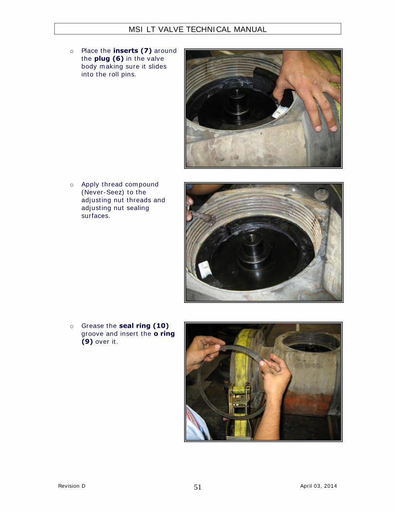
o Place the inserts (7) around
the plug (6) in the valve body making sure it slides
into the roll pins.
o Apply thread compound
(Never-Seez) to the
adjusting nut threads and adjusting nut sealing
surfaces.
o Grease the seal ring (10)
groove and insert the o ring
(9) over it.

MSI LT VALVE TECHNICAL MANUAL
Revision D April 03, 2014 52
o Place the seal ring (10) on
the top of the inserts.
o Install the adjusting nut
(12) into the valve body and tighten until snug and back
off ¼ turn from the snug position.
o Apply thread compound
(Never Seez) grease to the
plug bolt (14) threads and tighten it with the allen
wrench on the adjusting nut side of the plug (6).
MSI LT VALVE TECHNICAL MANUAL
Revision D April 03, 2014 53
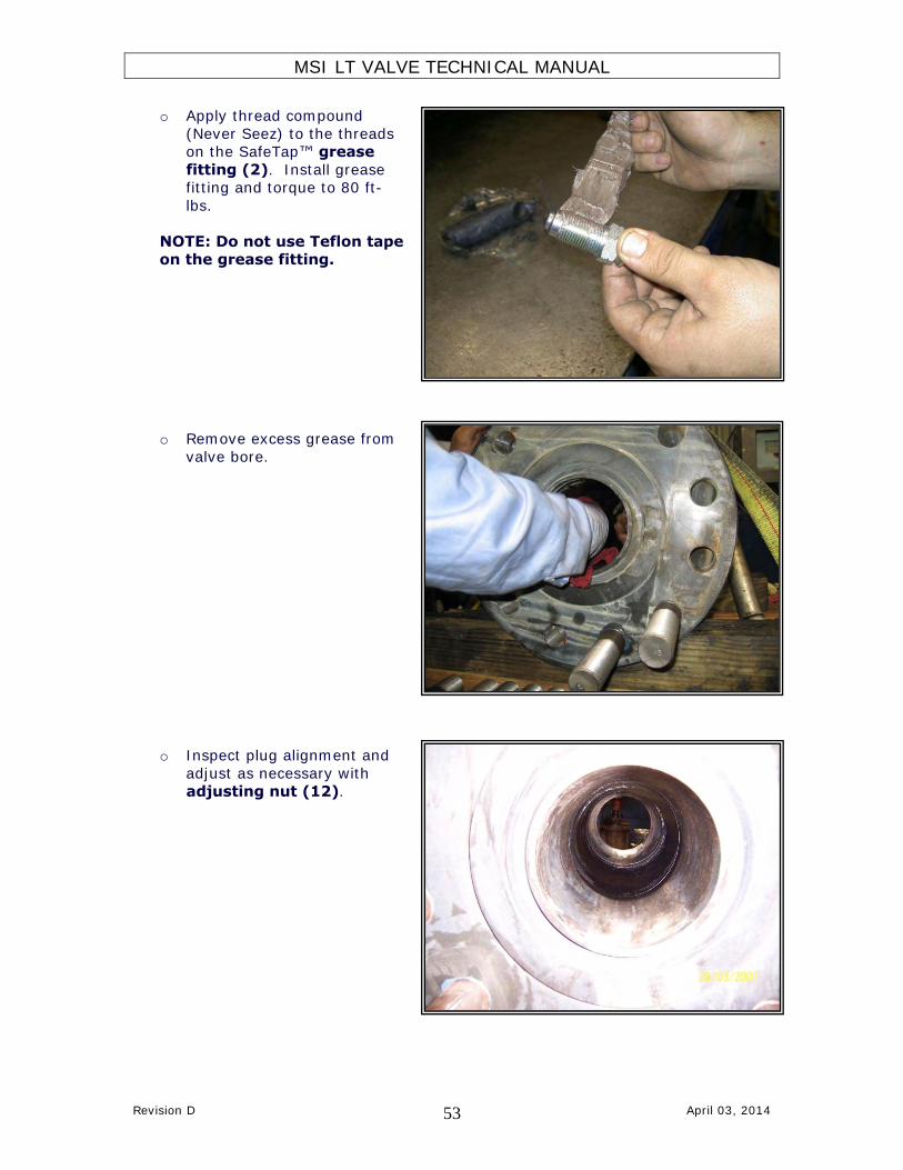
o Apply thread compound
(Never Seez) to the threads on the SafeTap™ grease
fitting (2). Install grease fitting and torque to 80 ft-
lbs.
NOTE: Do not use Teflon tape on the grease fitting.
o Remove excess grease from
valve bore.
o Inspect plug alignment and
adjust as necessary with
adjusting nut (12).

MSI LT VALVE TECHNICAL MANUAL
Revision D April 03, 2014 54
o Apply Removable
Threadlocker (blue) in the threads of the stud end and
screw the studs (3) until tight. Screw the nuts (4)
on the studs (3).
Note: Do not use Red High
Strength Threadlocker.

MSI LT VALVE TECHNICAL MANUAL
Revision D April 03, 2014 55
5.3 ASSEMBLY PROCEDURE- SPLIT INSERT (5” VALVE) (TEXT)
NOTE: It is imperative that the workstation being used to assemble the
valve be clean and free of anything that could possibly contaminate the grease such as metal shavings, dirt, rust, old paint, etc. Do not sand or
deburr near the workstation.
All assembly steps must be done with the valve pocket in the vertical
position. Any attempt to screw the adjusting nut in with the valve pocket in the horizontal position could result in damage to the adjusting nut and valve
sealing components.
1. Check surfaces around the valve bore inside the valve pocket for sharp edges
that could cause cutting of the insert o-rings. Then screw the clean adjusting nut (12) all the way into the valve body to make sure the threads
are not damaged.
2. After inspection remove the adjusting nut and check the roll pins (15 & 16)
in the valve body by gently sliding a set of inserts (7) into the valve. The inserts (7) should move freely up and down the length of the roll pin slots
without interference.
3. Apply a thin film of lubricant to the recess in the adjusting nut (12) and install the plug seal (5) with the metal back towards the recess facing away
from the pressure.
4. Apply grease to the plug seal (5) in the adjusting nut (12).
5. Grease the sealing groove and install the adjusting nut o ring (11) in the
groove.
6. Apply a thin film of lubricant to the pocket and the recess in the valve body (1) and install the plug seal (5) with the metal back towards the recess
facing away from the pressure.
7. 8. Check the plug (6) outside diameter for surface defects such as scratches,
dings, nicks, or sharp edges that could affect the sealing area. See 8.2 SANDING TIPS for repair.
9. Support the valve body (1) so that the plug hex can pass through
unobstructed.
10. Install the plug (6) (hex side down) in the valve body (1).
11. Check the surface finish of the inserts (7) making sure they do not have any
scratches, dings, nicks or sharp edges that could affect the sealing area. See 8.2 SANDING TIPS for repair.
12. Inspect the insert o-rings (8) for any possible non-conformity.

MSI LT VALVE TECHNICAL MANUAL
Revision D April 03, 2014 56
13. Install the insert o-rings (8) into the insert (7) grooves and coat with
grease to retain the rings.
14. Make sure the entire sealing surface is thoroughly greased.
15. Apply a thin film of grease to the entire I.D. of the insert set (7).
16. Place the inserts (7) around the plug (6) in the valve body (1) making sure it slides into the roll pins.
17. Apply thread compound (Never-Seez) to the adjusting nut (12) threads and adjusting nut (12) sealing surfaces.
18. Grease the seal ring (10) groove and insert the o ring (9).
19. Place the seal ring (10) on the top of the inserts (7).
20. Install the adjusting nut (12) into the valve body (1) and tighten until
snug and back off ¼ turn from the snug position.
21. Apply thread compound (Never Seez) grease to the plug bolt (14) threads
and tighten it with the allen wrench on the adjusting nut (12) side of the plug (6).
22. Apply thread compound (Never Seez) to the threads on the SafeTap™
grease fitting (2). Install grease fittings and torque to 80 ft-lbs. NOTE: Do not use Teflon tape on the grease fitting.
23. Remove excess grease from valve bore.
24. Inspect plug alignment and adjust as necessary with adjusting nut (12).
25. Apply Removable Threadlocker (blue) in the threads of the stud end and
screw the studs (3) until tight. Screw the nuts (4) over the studs (3) Note: Do not use Red High Strength Threadlocker.

MSI LT VALVE TECHNICAL MANUAL
Revision D April 03, 2014 57
6.0 DISASSEMBLY PROCEDURE Note: If handle adapter (4) or adjusting nut (14) appears to be stuck or locked,
pressure may be trapped in the valve. This is also known as “pressure locking.” Do not attempt to disassemble a “pressure locked” valve. See section 8.1
DISASSEMBLY TIPS for pressure relieving procedures.
o Remove the handle adapter (4) and stop collar (5). Turn valve over so that the adjusting nut (14) is facing up. Leaving the bottom plug bolt (1)
in place, screw out (turning counter-clockwise) the adjusting nut (14). This will allow the entire internal assembly (adjusting nut (14), plug (10) and
inserts (12)) to be removed from the valve pocket at once.
o Remove the plug bolt (1) that attaches the plug (10) to the adjusting nut
(14).
o Remove the plug (10) and inserts (12).
o Remove the insert o-rings (11), adjusting nut o-ring (13) and plug seals (9).
o Clean all of the old lubricant and debris from the parts and valve body internal profile.

MSI LT VALVE TECHNICAL MANUAL
Revision D April 03, 2014 58
7.0 MAINTENANCE
Valves should be greased as part of a regular maintenance program. Regular greasing will increase the service life of the internal valve parts. Routine
disassembly and cleaning as part of a maintenance program can prevent unnecessary damage to the valve body. Dixie Iron Works, Ltd. recommends that
valves be greased after every job or every 5 actuations, whichever one comes first.
Valves should be greased according to the severity of use. Each operating company
should establish guidelines for a greasing and/or disassembly program. These
guidelines should be based on the operating conditions. Special consideration should be given for conditions in which the following would be involved:
Abrasives in the fluid stream
High flow rates
Caustic or Acidic fluid streams
High Temperature
Fluid Streams that would act as solvents such as condensate
High number of valve actuations
Valves should not be greased while under pressure unless a Greaseal™ plug is being used. In addition, valves should not be disassembled for repair while part of an
operating arrangement such as a manifold. This should not be attempted even though the valve may be isolated from the fluid stream by other valves.
If the valve is NOT pressurized, MSI recommends greasing the valve to a minimum of 3,000 psi greasing pressure. If the valve is pressurized (and a Greaseal™ plug is
being used), the greasing pressure needs to be greater than the internal pressure of the valve, but always less than the rated working pressure of the valve. The
greasing pump must have pressure measuring capability.
Do not attempt to disassemble a “pressure locked” valve. See section 8.1 DISASSEMBLY TIPS for pressure relieving procedures.
MSI LT VALVE TECHNICAL MANUAL
Revision D April 03, 2014 59
8.0 REPAIR AND INSPECTION
When repairing a MSI plug valve, the following basic guidelines can help you ensure a good hydrostatic test of the reassembled valve.
Disassemble the valve completely. See section 6.0 DISASSEMBLY PROCEDURES
for detailed instructions on valve disassembly. Remove old grease and debris from
valve pocket with a solvent and inspect for wear or damage such as:
In the adjusting nut seal bore of the pocket: Scratches could be caused by previous installation of a damaged adjusting nut. Dings can also occur during
assembly. Pitting is usually caused by failure to disassemble and clean valves after they are in service. Use your fingers to feel for any surface defects
which may either fail to seal against the o-ring or may even damage the o-ring during assembly.
On the adjusting nut o-ring groove area: Check for scratches, dings, or
pitting. Dings and scratches here are usually caused by careless use of sharp metal objects when trying to remove old o-rings. Feel for any raised edges
that might scratch the internal seal bore of the valve body and sand or file as necessary.
On the adjusting nut threads: Check for damaged threads, especially the lead thread. Use your fingers to check for any raised edges and carefully sand as
needed. Severely damaged threads must be repaired at the factory. On the pocket walls: Scratches, dings, or pitting, especially in the area
immediately surrounding the valve bore. Use your fingers to feel for any
surface defects which may either fail to seal against the o-ring or may even damage the o-ring during assembly. Check for any sharp edges around the
valve bore that can cut the insert o-rings. These can be caused by using a bar when swabbing excess grease or using a bar to carry the valve.
On the internal threads: Check for damaged threads, especially the lead thread. Use your fingers to check for any raised edges and carefully sand as
needed. Severely damaged threads must be repaired at the factory. On the plug seal area: Check for scratches, dings, or pitting. Dings and
scratches here are usually caused by careless use of sharp metal objects
when trying to remove old seals. On the plug outside diameter: Check plug for washout, which will render the
part unusable. Hold part in a well illuminated area and inspect for slight scratches in plug. If scratches are visible, use a 600 grit sandpaper to
remove them.
On the insert inside diameter: Check segments for washout, which will render the
parts unusable. Hold parts up to a well illuminated area and inspect for slight
scratches in outer and inner diameters of inserts. If scratches are visible, use a 600 grit sandpaper to remove them.
MSI LT VALVE TECHNICAL MANUAL
Revision D April 03, 2014 60
If the flow bore is washed and eroded larger than when the bore I.D. was new, the
plug and segment set can only be used when the wear conforms to the guidelines detailed below. Since the bore will no longer be a perfect circle, you must measure
the largest gap from one side of the bore to the other. If the bore tapers in either direction, measure the largest dimension. Compare the measurement to the
following maximum acceptable dimensions:
1” Plugs and Inserts – 1.090” max 2” Plugs and Inserts – 2.120” max
3” Plugs and Inserts – 3.120” max
4” Plugs and Inserts – 4.120” max 5” Plugs and Inserts – 5.190” max
Plug valves seal on the downstream side or the side opposite the pressure. The o-
ring in the segment is pressured inward, trying to collapse the inside wall toward the bore. Dimensions larger than these guidelines will produce walls too thin to support
the working pressure of the valve and these parts should be scrapped.
Because the bore is larger than when new and because the eroded area tends to be
uneven, worn parts create a larger internal upset in the valve which increases turbulence. This increased turbulence means that the rate of wear will increase
exponentially so special consideration should be given to the application of valves with worn parts to minimize the possibility of failure during the course of the job.
Continued use of parts with eroded flow bores may reduce the life of the valve body. MSI recommends that valves with working but washed parts within these guidelines
be used in locations of the rig-up that see less abrasive flow.
See the Minimum Wall Thickness Datasheet for wall thickness inspection procedures and allowable erosion values.
MSI LT VALVE TECHNICAL MANUAL
Revision D April 03, 2014 61
8.1 DISASSEMBLY TIPS
Note: If handle adapter (4) or adjusting nut (14) appears to be stuck or locked, pressure may be trapped in the valve. This is also known as “pressure locking.” Do
not attempt to disassemble a “pressure locked” valve.
The SafeTap™ grease fitting allows for the safe relief of trapped pressure
within a valve. Extreme caution must be followed when attempting to relieve a pressure locking situation. Slowly turn the grease fitting ¼ CCW turn to
relieve the pressure. Actuate the valve to ensure all pressure has been relieved. After the removal of all trapped pressure, you may remove all
components. See section 1.1 SAFETAP™ GREASE FITTING for more details on the SafeTap™ grease fitting

MSI LT VALVE TECHNICAL MANUAL
Revision D April 03, 2014 62
8.2 SANDING TIPS
When repairing a MSI plug valve, the following basic guidelines can help you ensure a successful hydrostatic test of the reassembled valve.
Sanding is necessary to repair blemishes from the sealing surfaces of parts.
Sanding of scratches, dings, and pitting should always be done with 600 grit
sanding cloth that is well lubricated with water or solvent. When sanding sealing surfaces, it is VERY important to avoid sanding in one spot
continuously; sand evenly across the entire sealing surface. Sand scratches by moving the sandpaper around the plug, not up and down, along the
length of the plug. If scratches cannot be removed utilizing this technique,
replace the parts. If raised edges or dings in non-sealing areas are too large to be sanded effectively, you may use a rotary flapper-type sanding wheel.
It is very important that you do not remove any material other than the actual raised edge. Do not remove any of the base material or you may
permanently damage the valve and render it unsafe for use.

MSI LT VALVE TECHNICAL MANUAL
Revision D April 03, 2014 63
8.3 ASSEMBLY TIPS
When repairing a MSI plug valve, the following basic guidelines can help
you ensure a good hydrostatic test of the reassembled valve.
If you choose to mix old and new parts, you must make absolutely sure that the old
part does not have any defects. Using 600 grit sanding cloth, wet sand any surface blemishes as described in section 8.2 Sanding Tips.
See section 3.0 ASSEMBLY PROCEDURES for detailed assembly
instructions.

MSI LT VALVE TECHNICAL MANUAL
Revision D April 03, 2014 64
9.0 STORAGE
Disassemble the valve completely. See section 6.0 DISASSEMBLY PROCEDURES for detailed instructions on valve disassembly. Remove old grease and debris from
valve pocket with a solvent and inspect for wear or damage per 8.0 REPAIR AND INSPECTION.
Drain after testing. All equipment should be drained and lubricated after
testing and prior to storage.
All components and assemblies should be cleaned of dirt, rust, and other
contaminants.
Rust Prevention: Equipment should have exposed metallic surfaces protected
with a rust inhibitor which will not become fluid and run at a temperature less than 125°F (52°C).
Sealing surface protection: Exposed sealing surfaces should be protected from
mechanical damage.

MSI LT VALVE TECHNICAL MANUAL
Revision D April 03, 2014 65
9.1 SHELF LIFE
The following is recommended for maximum equipment shelf life:
# of Months in Storage
Manufacturers Recommendations
0-3 months Nothing required
3-6 months Re-grease and operate. Operate by rotating the plug. Check to see
that rotation is smooth without grinding or scraping. 6+ months Disassemble, rebuild & retest the valve. Replace all internal seals
MSI LT VALVE TECHNICAL MANUAL
Revision D April 03, 2014 66
10.0 ACCESSORIES
Use only MSI recommended accessories.
MSI Part Number Description
VC0393 Valve Operating Bar

MSI LT VALVE TECHNICAL MANUAL
Revision D April 03, 2014 67
10.1 GREASES
Use only MSI recommended greases. Greases intended for gate valves or other applications may result in failure to achieve a good test and may actually damage
the new parts.
MSI Part Number Description Manufacturer's
Website
VC0012 #972 General Service (size K) Val-Tex
VC0426 #972 General Service (size 5.5) Val-Tex
VC0669 #972 General Service (size V) Val-Tex VC0527 #750 Low Temperature (size J) Val-Tex
VC0402 #750 Low Temperature (size K) Val-Tex VC0357 #700 CO2 / Hi-Temp / Condensate (size J) Val-Tex
GREASE002 * 1502-S-7 Low Pressure Testing (7 lb can) Val-Tex
*Val-Tex 1502 grease is for hand application only and not to be pumped. Therefore, it is to be used only during the assembly process. Inject body grease prior to testing
and after each actuation.

MSI LT VALVE TECHNICAL MANUAL
Revision D April 03, 2014 68
10.2 GREASE REQUIREMENTS
Valve Size Approximate amount of grease “K” size stick
1” VALVE ⅓ STICK
2” VALVE ½ STICK
3” VALVE 1 STICK
4” VALVE 3 STICKS
5” VALVE 5 STICKS

MSI LT VALVE TECHNICAL MANUAL
Revision D April 03, 2014 69
10.3 ACTUATORS
MSI uses the following brands of actuators. Information is available by clicking on the hyperlinks.
Pneumatic El-O-Matic
Hydraulic Damcos
Gear Operated Williams Machine

MSI LT VALVE TECHNICAL MANUAL
Revision D April 03, 2014 70
10.4 RUBBER PRODUCTS
MSI offers many 0-ring and plug seal materials for a variety of environmental and operating conditions.