automatic greasing system twin-3 - gkb equipment · automatic greasing system twin-3 general...
TRANSCRIPT
General Manual
Automatic Greasing SystemTwin-3
EG1703P04
Your efficiency is our Challenge!
Twin

All rights reserved. No part of this manual may be copied and/or published by means of printing, photocopying,microfilm or by any other means without prior written permission from Groeneveld. This applies also to thedrawings and diagrams appended.
Groeneveld reserves the right to change parts at any time, without prior or direct notice to the customer. Thecontents of this manual may also be changed without prior notice.
This manual applies to the standard version of the product. Groeneveld cannot accept liability for any damagearising from the use of specifications other than that supplied.
You are requested to contact Groeneveld technical service for information concerning adjustment, maintenancework or repairs that is not described in this manual.
Whilst this manual has been prepared with the greatest possible care Groeneveld cannot accept responsibility forany errors of the concequences of such errors.
General information
Type of manual General Manual
System Automatic Greasing System Twin-3
Document number EG1703P04
Date of issue September 2011
Revision 04
Automatic Greasing System Twin-3
Dat
e o
f is
sue
: Sep
tem
ber
201
1
Table of Contents
Preface - - - - - - - - - - - - - - - - - - - - - - - - - - - - - - - - - - - - - - - - - - - - - - - - - - - - - - - 5
1. General information - - - - - - - - - - - - - - - - - - - - - - - - - - - - - - - - - - - - - - - - - - - - - 61.1. Introduction- - - - - - - - - - - - - - - - - - - - - - - - - - - - - - - - - - - - - - - - - - - - - - - - - - - - - - - - - 61.2. The Twin automatic greasing system - - - - - - - - - - - - - - - - - - - - - - - - - - - - - - - - - - - - - - 6
2. Principle of operation - - - - - - - - - - - - - - - - - - - - - - - - - - - - - - - - - - - - - - - - - - - - 82.1. Introduction- - - - - - - - - - - - - - - - - - - - - - - - - - - - - - - - - - - - - - - - - - - - - - - - - - - - - - - - - 82.2. Greasing cycle - - - - - - - - - - - - - - - - - - - - - - - - - - - - - - - - - - - - - - - - - - - - - - - - - - - - - - - 8
2.2.1. Greasing cycle A - - - - - - - - - - - - - - - - - - - - - - - - - - - - - - - - - - - - - - - - - - - - - - - 82.2.2. Greasing cycle B - - - - - - - - - - - - - - - - - - - - - - - - - - - - - - - - - - - - - - - - - - - - - - - 9
2.3. Twin pump unit - - - - - - - - - - - - - - - - - - - - - - - - - - - - - - - - - - - - - - - - - - - - - - - - - - - - - 102.3.1. Control unit - - - - - - - - - - - - - - - - - - - - - - - - - - - - - - - - - - - - - - - - - - - - - - - - - 112.3.2. 5/2 way valve - - - - - - - - - - - - - - - - - - - - - - - - - - - - - - - - - - - - - - - - - - - - - - - - 142.3.3. Relief valve- - - - - - - - - - - - - - - - - - - - - - - - - - - - - - - - - - - - - - - - - - - - - - - - - - 142.3.4. Test push button - - - - - - - - - - - - - - - - - - - - - - - - - - - - - - - - - - - - - - - - - - - - - 142.3.5. Grease reservoir and its follower plate - - - - - - - - - - - - - - - - - - - - - - - - - - - - - 152.3.6. Minimum level switch- - - - - - - - - - - - - - - - - - - - - - - - - - - - - - - - - - - - - - - - - - 15
2.4. Distribution block and metering units- - - - - - - - - - - - - - - - - - - - - - - - - - - - - - - - - - - - - 162.4.1. Principle of operation- - - - - - - - - - - - - - - - - - - - - - - - - - - - - - - - - - - - - - - - - - 17
2.5. Pressure switch- - - - - - - - - - - - - - - - - - - - - - - - - - - - - - - - - - - - - - - - - - - - - - - - - - - - - - 192.5.1. Principle of operation- - - - - - - - - - - - - - - - - - - - - - - - - - - - - - - - - - - - - - - - - - 19
2.6. Signal lamp - - - - - - - - - - - - - - - - - - - - - - - - - - - - - - - - - - - - - - - - - - - - - - - - - - - - - - - - 212.7. Duty mode push-button - - - - - - - - - - - - - - - - - - - - - - - - - - - - - - - - - - - - - - - - - - - - - - - 212.8. Twin-3 display - - - - - - - - - - - - - - - - - - - - - - - - - - - - - - - - - - - - - - - - - - - - - - - - - - - - - - 22
2.8.1. Decimal dot of the 3-digit display - - - - - - - - - - - - - - - - - - - - - - - - - - - - - - - - - 23
3. System test - - - - - - - - - - - - - - - - - - - - - - - - - - - - - - - - - - - - - - - - - - - - - - - - - - - 243.1. Introduction- - - - - - - - - - - - - - - - - - - - - - - - - - - - - - - - - - - - - - - - - - - - - - - - - - - - - - - - 243.2. Single greasing cycle test - - - - - - - - - - - - - - - - - - - - - - - - - - - - - - - - - - - - - - - - - - - - - - 253.3. Multiple greasing cycle test - - - - - - - - - - - - - - - - - - - - - - - - - - - - - - - - - - - - - - - - - - - - 263.4. Fast automatic cycle session - - - - - - - - - - - - - - - - - - - - - - - - - - - - - - - - - - - - - - - - - - - - 273.5. Resetting the system - - - - - - - - - - - - - - - - - - - - - - - - - - - - - - - - - - - - - - - - - - - - - - - - - 27
4. Maintenance - - - - - - - - - - - - - - - - - - - - - - - - - - - - - - - - - - - - - - - - - - - - - - - - - - 284.1. General - - - - - - - - - - - - - - - - - - - - - - - - - - - - - - - - - - - - - - - - - - - - - - - - - - - - - - - - - - - 284.2. Periodic checks - - - - - - - - - - - - - - - - - - - - - - - - - - - - - - - - - - - - - - - - - - - - - - - - - - - - - - 284.3. Bleeding the pump- - - - - - - - - - - - - - - - - - - - - - - - - - - - - - - - - - - - - - - - - - - - - - - - - - - 284.4. Bleeding the system - - - - - - - - - - - - - - - - - - - - - - - - - - - - - - - - - - - - - - - - - - - - - - - - - - 294.5. Refilling the grease reservoir - - - - - - - - - - - - - - - - - - - - - - - - - - - - - - - - - - - - - - - - - - - 30
4.5.1. Grease recommendations - - - - - - - - - - - - - - - - - - - - - - - - - - - - - - - - - - - - - - - 304.5.2. Filling the reservoir- - - - - - - - - - - - - - - - - - - - - - - - - - - - - - - - - - - - - - - - - - - - 30
4.6. Finding malfunctions - - - - - - - - - - - - - - - - - - - - - - - - - - - - - - - - - - - - - - - - - - - - - - - - - 314.6.1. General - - - - - - - - - - - - - - - - - - - - - - - - - - - - - - - - - - - - - - - - - - - - - - - - - - - - 314.6.2. Recognizing malfunctions- - - - - - - - - - - - - - - - - - - - - - - - - - - - - - - - - - - - - - - 314.6.3. Malfunction finding table- - - - - - - - - - - - - - - - - - - - - - - - - - - - - - - - - - - - - - - 324.6.4. Retrieving a fault code message by signal lamp- - - - - - - - - - - - - - - - - - - - - - - 404.6.5. Malfunction finding procedures - - - - - - - - - - - - - - - - - - - - - - - - - - - - - - - - - - 41
5. Technical data - - - - - - - - - - - - - - - - - - - - - - - - - - - - - - - - - - - - - - - - - - - - - - - - - 445.1. Twin pump unit - - - - - - - - - - - - - - - - - - - - - - - - - - - - - - - - - - - - - - - - - - - - - - - - - - - - - 445.2. Signal lamp - - - - - - - - - - - - - - - - - - - - - - - - - - - - - - - - - - - - - - - - - - - - - - - - - - - - - - - - 455.3. Twin display - - - - - - - - - - - - - - - - - - - - - - - - - - - - - - - - - - - - - - - - - - - - - - - - - - - - - - - - 46
3Table of ContentsEG1703P04

4
Automatic Greasing System Twin-3
Date o
f issue : Sep
temb
er 2011
Table of Contents EG1703P04

Automatic Greasing System Twin-3
Dat
e o
f is
sue
: Sep
tem
ber
201
1
Preface
This general manual gives a description of the Twin automatic greasing system. It aims at givinginsight in the system’s operation and possibilities. Furthermore, in this manual you will find thetechnical data on several components of the Twin automatic greasing system.
In this manual the following icons are used to inform or warn the user:
Use of symbols
ATTENTION
Draws the user's attention to important additional information meant to avoid problems.
WARNINGWarns the user for physical injuries or serious damage to the equipment caused by improper ac-tions.
Symbol Explanation
BK Black
BN Brown
BU Blue
GN Green
GY Grey
OR Orange
PK Pink
PS Pressure Switch
PU Purple
RD Red
WH White
YE Yellow
Preface 5EG1703P04

6
Date o
f issue : Sep
temb
er 2011
Automatic Greasing System Twin-3
1 General information
1.1 Introduction
With an automatic greasing system of Groeneveld all grease points of a vehicle or machine arelubricated automatically at the correct moment and with the correct amount of grease. Becausegreasing takes places while the vehicle or machine is in operation, the applied grease is spreadoptimally over the whole surface to be greased. The greasing system requires no user interventionto operate, apart from periodically replacing the grease in its reservoir.
Groeneveld’s automatic greasing systems are designed with the utmost care and tested rigorously.This guarantees an extended operational life and error-free operation, even under the mostextreme operating conditions.
Proper installation, using the correct type of grease, and periodic checks are prerequisites for thecontinual hassle-free operation of the system. The periodic checks, which take little time and effort,can be performed during the normal maintenance of the vehicle or machine (during oil-replacement, for instance). Careful selection of construction materials, makes the greasing systemitself nearly maintenance-free.
1.2 The Twin automatic greasing system
Groeneveld has developed a double-line automatic greasing system especially for the use of NLGIclass-2 grease. The Twin system ensures that all the disadvantages of the systems currently availablefor class-2 grease are eliminated.
The Twin system has all advantages of the Groeneveld single-line systems. This means, for instance,that the system is expandible trouble-free with grease points that are installed afterwards (extramachine equipment).
The advantages of the Twin system:
• ingenuous and fast assembly;• modular expansion possible;• parts of the system can (temporarily) be coupled or uncoupled;• clear malfunction reports;• registration of possible malfunctions;• the grease dosage can easily be adjusted per greasing point to the needs of that particular
greasing point;• the grease dosage per greasing point remains constant under all circumstances.
ATTENTIONThe automatic greasing system reduces the time and effort spent on manual greasing significantly.However, do not forget that there may be grease points that are not served by the greasing systemand must still be greased by hand.
General information EG1703P04

Automatic Greasing System Twin-3
Dat
e o
f is
sue
: Sep
tem
ber
201
1
A Groeneveld Twin automatic greasing system comprises the following parts (see Figure 1.1):
1. An electric grease pump (plunger pump) with integrated grease reservoir and a digital control unit with data storage facility
2. Primary grease line A3. Primary grease line B4. Distribution block5. Metering unit6. Pressure switch7. Secundary grease line
Figure 1.1 System overview
TWIN
1
3
5
6
2 4
7
General information 7EG1703P04

8
Date o
f issue : Sep
temb
er 2011
Automatic Greasing System Twin-3
2 Principle of operation
2.1 Introduction
In this chapter the principles of operation of the various parts of the Twin automatic greasingsystem are discussed. The greasing cycle, pump unit, control unit, metering units, pressure switch,signal lamp and Twin-3 display are discussed.
2.2 Greasing cycle
Every greasing cycle consists of four phases. The greasing cycles are performed alternately by thegrease lines-A and -B (see Figure 2.1). The 5/2-way valve, which is integrated in the pump housing,determines which primary grease line is connected to the pump and which is connected to thegrease reservoir. The total greasing cycle has a predetermined time; the length of the four phasesdepend on the circumstances. The different greasing cycles and phases are discussed below.
Figure 2.1 Overview of the various phases of the greasing cycle
2.2.1 Greasing cycle A
Pumping phase
The greasing cycle begins with a pumping phase. In this phase the grease is pumped from thereservoir, through primary grease line-A, to the distribution blocks. The pumping phase ends whenthe pressure at the pressure switch reaches a predetermined level. The time needed to reach thatpredetermined pressure depends on various factors as temperature, grease consistency (thickness)and the dimensions of the greasing system.
During the pumping phase, the metering units press a certain amount of grease (the dosage)through the secondary grease lines to the grease points.
Cycle A Cycle B
pump
pressure retaining
phase
pressure decrease
phase
pause phase
pumping phase pressure retaining
phase
pressure decrease
phase
pause phase
5/2 valve
pressure pathprimary line-A
pressure pathprimary line-B
pumping phase
Principle of operation EG1703P04

Automatic Greasing System Twin-3
Dat
e o
f is
sue
: Sep
tem
ber
201
1
Pressure retaining phase
The pressure retaining phase follows the pumping phase; a period in which the pressure in theprimary grease line-A is maintained at a certain pressure. During the pressure retaining phase, themetering units can deliver the grease dosage, which (for various reasons) was not yet deliveredduring the pumping phase. The duration of the pressure retaining phase depends on the durationof the pumping phase. This dependency is expressed in the parameter vmf, venting multiply factor.Example: When the vmf is 1.0 the pressure retaining phase is the same length as the pumping
phase. When the vmf is set to 10.0, the pressure retaining phase is 10 times the lengthof the pumping phase.
Pressure decrease phase
The pressure decrease phase follows the pressure retaining phase. In this phase, the pressure in theprimary grease line-A is decreased through the 5/2-way valve. To accomplish this, the control unitswitches the 5/2-way valve on, so the grease pressure in the primary grease line-A is decreased andthe grease flows back to the reservoir.
The duration of the pressure decrease phase is equal to that of the pressure retaining phase andtherefore proportional to the duration of the pumping phase. When the greasing system needsmore time to build up the required grease pressure (because of low temperature or grease with ahigh viscosity), the system will also need more time to decrease that same pressure.
Pause phase
The pause phase is the period between the pressure decrease phase and the beginning of the nextpumping phase in line-B. The length of the pause phase is equal to the predetermined cycle-timeminus the length of the other phases. When the cycle-time is adjusted too short to perform acomplete greasing cycle, the program will ignore the cycle-time. The pumping-, pressure retainingand pressure decrease phase will be performed completely. However the pause phase will beomitted, because the predetermined cycle-time is exceeded. The greasing system begins directlywith the first phase of the next greasing cycle.
2.2.2 Greasing cycle B
Greasing cycle B begins when the pause phase of the former cycle A is finished. The control unitrestarts the pump. During pumping phase B and pressure retaining phase B, the control unitswitches the 5/2-way valve on, causing the pump to be connected to primary grease line-B. Theprimary grease line-A is shut off from the pump during these phases and connected to the reservoir.During the pressure decrease phase in primary grease line-B, the control unit switches the 5/2-wayvalve (spring return) off, so the grease pressure in the primary grease line-B decreases and thegrease flows back to the reservoir.
Principle of operation 9EG1703P04

10
Date o
f issue : Sep
temb
er 2011
Automatic Greasing System Twin-3
2.3 Twin pump unit
The Twin pump unit consists of various parts. These parts are shown in Figure 2.2.
Figure 2.2 Twin pump unit
The heart of the pump is an electrical-driven piston-pump. This pump consists of three radially-placed fixed cylinders and pistons (5). The electromotor drives the axle through the mechanicaltransmission (9). A cam (4) is fixed on the axle that moves the three pistons to and fro, so the greaseis pumped to the distribution blocks through the primary grease lines. In addition to the cam, theaxle drives the stirring gear (3) located at the bottom of the reservoir and pushes the greasedownwards. A compression channel is located between the pump and the grease channels to theprimary lines. A relief valve (14) and a 5/2-way valve (6) are located in the compression channel.
The relief valve is a protection that leads the grease back to the reservoir when the grease pressureexceeds 250 bar. The 5/2-way valve determines the primary grease line-A or -B through whichgreasing takes place. It has an important task in fulfilling the four phases of the greasing cycle (seeparagraph 2.2).
1
2
3
4
5
6
7
8
9
12
11
10
13
14
15
16
17
18
19
1. Follower plate2. Grease reservoir3. Stirring gear4. Cam5. Cylinder and pistons (3x)6. 5/2-way valve7. Primary grease line-A outlet8. Primary grease line-B outlet9. Mechanical transmission
10. Electro-motor11. Control unit12. Test push-button13. Filler coupling with grease filter14. Relief valve15. Bleeding and grease overflow out-
let16. Electric connector17. Minimum level switch
18. Guide rod follower plate19. Bleeding and grease overflow
channel, connected to the bleeding and grease overflow outlet (no. 15)
Principle of operation EG1703P04

Automatic Greasing System Twin-3
Dat
e o
f is
sue
: Sep
tem
ber
201
1
2.3.1 Control unit
The electronic control unit steers and controls the course of the greasing cycles. All system- andprogram-parameters are stored in it. The control unit processes malfunction reports, gives possiblealarm reports and automatically records a log. All relevant incidents will be stored in the log.
All data in the control unit will always be retained, even when the power or system is switched OFF.To view the log an Uni- or PC-GINA is needed.
The control unit is electrically connected according to the wiring diagram shown (see Figure 2.3).The positive pole of the supply voltage (+15) is connected to pin-1.As soon as the ignition is switched ON, the program cycle is started at the point where it wasinterrupted during the preceding cycle.If the preceding cycle was interrupted during the pumping phase by switching OFF ignition, thispumping phase will be continued the moment ignition is switched ON again.
Figure 2.3 Wiring diagram with signal lamp
PUMP
L
T
BK
RD
OR
BU
GY
PU
P
I
+-
M
1 +15
3
7 PS
8
6 K
5
PS
4 +SL
2 GND
VAL1
PUMPPOWER
J5
VAL2
LOW
TEST
J83 4
1
2
3
4
5
6
7
8
9
10
11
22K
12V 20A
24V 10A
1. Electric motor of pump2. 5/2-way valve3. Minimum level switch4. Test push-button
5. Control unit6. Pump housing7. Battery8. Ignition switch
9. Pressure switch10. Greasing cycle selector switch11. Signal lamp
Principle of operation 11EG1703P04

12
Date o
f issue : Sep
temb
er 2011
Automatic Greasing System Twin-3
Vehicles or machines of which the actual operation time is much shorter than the ignition time, theconnected grease points could easily get over greased. In order to prevent this, the interval timercan be stopped for the time the vehicle or machine is not in operation, while the ignition isswitched ON. Figure 2.4 shows how to connect the control unit in this situation.Pin-1 and -2 are, as in the other diagram, connected to ignition and ground. Pin-3 is the additionalconnection for starting or stopping the interval timer on demand. Depending on the availableelectrical connection at the vehicle or machine, the interval timer can be started when:• power to pin-3 is switched ON• power to pin-3 is switched OFF• ground to pin-3 is switched ON• ground to pin-3 is switched OFF
Please refer to the Twin-3 Uni- or PC-GINA manual for the necessary parameter settings in order toactivate one of the above mentioned possibilities.
Figure 2.4 Wiring diagram with command switch and Twin-3 display
TWIN
Automat cG ea ingSystem
SW TCH
PUMP
L
12V 20A
24V 10A
22K
12V 3A
24V 3A
T
BK
RD
GN
BU
GY
WH
YE
PU
P
I
+-
I
+/-1 +15
3
7 PS
8
6 K
5
PS
4 +SL
2 GND
VAL1
PUMPPOWER
J5
J83 4
VAL2
LOW
TEST
1
2
3
4
5
6
7
8
9
10
11
12
13
141. Electric motor of pump2. 5/2-way valve3. Minimum level switch4. Test push-button5. Control unit6. Pump housing7. Battery
8. Ignition switch9. Command switch (+ or -, normally opened or closed)10. Pressure switch11. Twin-3 display12. Error signal output-1 (max 6W), -31 ground13. Low level signal output-2 (max 6W), -31 ground14. Additional in- output connection
Principle of operation EG1703P04

Automatic Greasing System Twin-3
Dat
e o
f is
sue
: Sep
tem
ber
201
1
Figure 2.5 Wiring diagram OEM pump with CANbus
IMPORTANTThe internal wiring of an OEM/CANbus pump is different from standard. Activating the CANbusoption in the control unit with a diagnosis device therefore will only be useful in combination withsuch a pump (see internal wiring of pump connector pin-4 and -5).
PUMP
L
12V 20A
24V 10A
22K
12V 3A
24V 3A
T
BK
RD
GN
BU
GY
PK
OR
P
I
+-
I
+/-
CANCPU
1 +15
3
7 PS
8
6 K
5
PS
4 L
H
2 GND
VAL1
PUMPPOWER
J5
J83 4
VAL2
LOW
TEST
1
2
3
4
5
6
7
8
9
10
11
1. Electric motor of pump2. 5/2-way valve3. Minimum level switch4. Test push-button5. Control unit6. Pump housing
7. Battery8. Ignition switch9. Additional switch (+ or -, normally opened or closed)10. Pressure switch11. CAN CPU
Principle of operation 13EG1703P04
14
Date o
f issue : Sep
temb
er 2011
Automatic Greasing System Twin-3
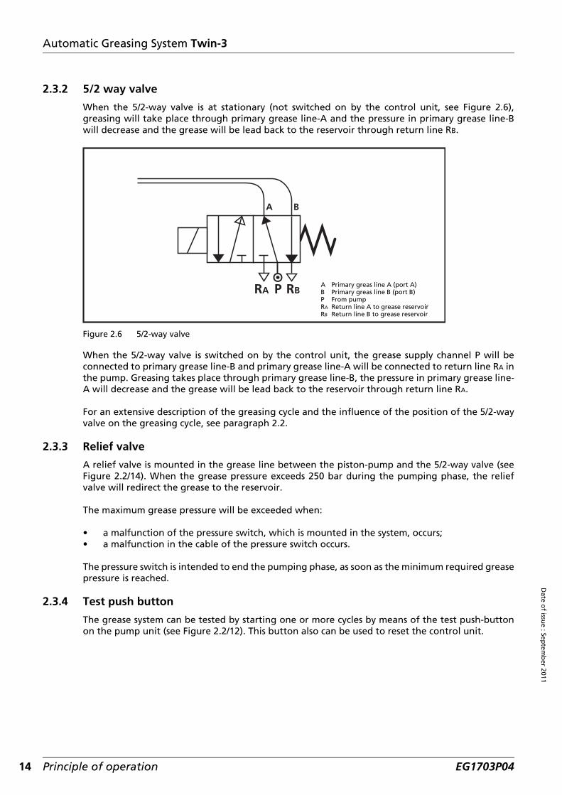
2.3.2 5/2 way valve
When the 5/2-way valve is at stationary (not switched on by the control unit, see Figure 2.6),greasing will take place through primary grease line-A and the pressure in primary grease line-Bwill decrease and the grease will be lead back to the reservoir through return line RB.
Figure 2.6 5/2-way valve
When the 5/2-way valve is switched on by the control unit, the grease supply channel P will beconnected to primary grease line-B and primary grease line-A will be connected to return line RA inthe pump. Greasing takes place through primary grease line-B, the pressure in primary grease line-A will decrease and the grease will be lead back to the reservoir through return line RA.
For an extensive description of the greasing cycle and the influence of the position of the 5/2-wayvalve on the greasing cycle, see paragraph 2.2.
2.3.3 Relief valve
A relief valve is mounted in the grease line between the piston-pump and the 5/2-way valve (seeFigure 2.2/14). When the grease pressure exceeds 250 bar during the pumping phase, the reliefvalve will redirect the grease to the reservoir.
The maximum grease pressure will be exceeded when:
• a malfunction of the pressure switch, which is mounted in the system, occurs;• a malfunction in the cable of the pressure switch occurs.
The pressure switch is intended to end the pumping phase, as soon as the minimum required greasepressure is reached.
2.3.4 Test push button
The grease system can be tested by starting one or more cycles by means of the test push-buttonon the pump unit (see Figure 2.2/12). This button also can be used to reset the control unit.
P A Primary greas line A (port A)B Primary greas line B (port B)P From pumpRA Return line A to grease reservoirRB Return line B to grease reservoir
Principle of operation EG1703P04

Automatic Greasing System Twin-3
Dat
e o
f is
sue
: Sep
tem
ber
201
1
2.3.5 Grease reservoir and its follower plate
The reservoir (see Figure 2.2/2) is made of a transparant, impact-proof plastic that resists the affectof variable temperatures and other enviromental influences.The volume of the reservoir depends on its height. The maximum grease level is indicated on thereservoir. A warning signal in the cabin indicates when the minimum level has been reached.
A follower plate (see Figure 2.2/1) is located in the reservoir, above the grease. This piston followsthe level of the grease. When the grease level falls, the piston also falls under the influence of adraw spring. The grease follower plate locks out air and condensation, so preventing:
• oxidation of the grease;• mingling of the grease with the water of condensation;• saponifying of the grease.
The grease level in the reservoir can always be determined at a glance, because the grease followerplate scrapes the walls of the reservoir. Also the follower plate prevents funnel-forming in thegrease, so the grease supply can and will be used in its entirety.
2.3.6 Minimum level switch
A minimum level switch monitors the grease level in the reservoir (see Figure 2.2/17). When thegrease reaches the minimum level, this switch will notify the control unit. At the beginning of everyfollowing greasing cycle a signal lamp in the cabin will flash or the yellow and green LED along withindication LO at the Twin-3 display is lit continuously as a warning that the reservoir has to berefilled.
Principle of operation 15EG1703P04

16
Date o
f issue : Sep
temb
er 2011
Automatic Greasing System Twin-3
2.4 Distribution block and metering units
Various types of metering units with the Twin greasing system are available, each with a differentgrease output. Each grease point can receive the correct dose of grease per greasing cycle by acareful choice of the type of metering unit.
Figure 2.7 Distribution block with metering units
The metering units are mounted on a distribution block per group. The distribution blocks aredeliverable with 2, 3, 4, 5, 6, 7, 8, 9, 12, 14, 18, 20, 21 or 22 ports (exits).Grease points are connected to these ports through metering units and secondary grease lines.Unused ports are sealed with a blind plug. A pressure switch can also be mounted into one of theports.
Because of their closed construction the metering units are exceptionally well suitable for use indirty and dusty environment.
The metering units and distribution blocks are made of brass or stainless steel. The various meteringunits are distinguished from each other using numbers (see Figure 2.7/3). The table below is anoverview of the various metering unit numbers and their grease capacity.
Metering unit num-ber
Grease capacity (cm³) per cycle
Metering unit num-ber
Grease capacity (cm³) per cycle
0 0,025 7 0,350
1 0,050 8 0,400
2 0,100 8,5 0,700
3 0,150 9 1,000
4 0,200 10 2,000
5 0,250 11 4,000
6 0,300
2 4
4 8
712.
01
43-0
7
100b
ar
4
3
1 2
1. Part number2. Production week / year3. Metering unit number4. Pressure switch
Principle of operation EG1703P04

Automatic Greasing System Twin-3
Dat
e o
f is
sue
: Sep
tem
ber
201
1
2.4.1 Principle of operation
Two grease chambers are located in a metering unit (one for each primary grease line, A and B).These chambers are filled with an exact amount of grease. When the actual greasing takes placesthrough one of both chambers, the grease is pressed from the chambers to the relevant greasepoint. The principle of operation of the metering unit is explained in the four phases below.
Phase 1
In this phase the metering unit has not yet been filled with grease.
Figure 2.8 First phase
While in operation (system completely filled with grease) phases 3 and 4 will take place alternately.
Phase 2
During pumping phase A grease is pressed into channel A. While the grease pressure is built up,piston (3) is pushed to the right, passed channel (1). The grease fills chamber (2) through channel(1) and pushes piston (4) to the right.
Figure 2.9 Second phase
After a while, the pressure drops in the primary grease line-A (during the pressure decrease phaseof the greasing cycle). This has no influence on the metering unit.
ATTENTION
Do not open the metering units. Prevent intrusion of dirt and thus a possible cause of malfunction.
3 1 2 4
A
Principle of operation 17EG1703P04

18
Date o
f issue : Sep
temb
er 2011
Automatic Greasing System Twin-3
Phase 3
During pumping phase B grease is pressed into channel B (6). While the grease pressure is built up,piston (3) is pushed back leftwards, passed channel (8). The grease fills chamber (7) and pushespiston (4) back to the left. The complete grease volume of chamber (2), left of piston (4), is pressedthrough channel (1), piston (3), channel (9) and the secondary grease line (5) to the grease point.Sphere (10) in the non-return valve is pushed back to clear the path to the secondary grease line.
Figure 2.10 Third phase
After a while, the pressure drops in the primary grease line-B (during the pressure decrease phaseof the greasing cycle). This has no influence on the metering unit.
Phase 4
In this phase the same happens as in phase 2. However chamber (Figure 2.10/7) is now filled withgrease. Piston (4) is pushed to the right while chamber (2) is filled. The complete grease volume ofchamber (Figure 2.10/7) is pressed through channel (8), piston (3), channel (9) and the secondarygrease line (5) to the grease points. Sphere (10) in the non-return valve is pushed back to clear thepath to the secondary grease line.
Figure 2.11 Fourth phase
7 4
3
1 9 10 6 8 5 2
B
3 2 8 5 4 9 10
A
Principle of operation EG1703P04

Automatic Greasing System Twin-3
Dat
e o
f is
sue
: Sep
tem
ber
201
1
2.5 Pressure switch
The pressure switch notifies the control unit that sufficient pressure has been built up during thepumping phase and stops the pump. When the required pressure is not reached, the pumpingphase is only ended after reaching the set maximum pumping time. An alarm will follow (signallamp).
Preferably the pressure switch is mounted on the distribution block, located the farthest from thepump. This is done to be sure that the required grease pressure of 100 bar also reaches the last dis-tribution block. When for practical considerations the switch is placed somewhere in the middle orat the beginning of the greasing system, a switch with a higher switch-pressure is applied. Pressureswitches are delivered with switch-pressures of 100, 125, 150 or 175 bar.
2.5.1 Principle of operation
The principle of operation of the pressure switch is explained in three phases.
Phase 1
During this phase no pressure is on channel A and B. There is also no pressure in chamber (1). Spring(10) pushes switch piston (2) to the left. The electrical contact (3 and 4) is open.
Figure 2.12 First phase
Phase 2
During pumping phase A grease is pressed into channel A. While the grease pressure is built up,piston (6) is pushed to the right. Chamber (1) is connected to channel A (through the channels 7, 8and 9).
As soon as the pressure in chamber (1) is more than the pressure force of the spring (10), piston (2)goes to the right. The electrical contact (3 and 4) is closed by the contact plate (5).
B
A
1 2 10 3
4
Principle of operation 19EG1703P04

20
Date o
f issue : Sep
temb
er 2011
Automatic Greasing System Twin-3
Figure 2.13 Second phase
During the pressure decrease phase, as soon as the grease pressure in channel A is lower than thepressure force of the spring, the connection of the electrical contacts is broken.
Phase 3
During pumping phase B grease is pressed into channel B. While the grease pressure is built up,chamber (11) fills with grease (through channel 12). The grease pressure pushes piston (6) to theleft. Because of that the channel (8) is opened, causing the grease to flow to chamber (1) throughchannel (7 and 9).
As soon as the pressure in chamber (1) is higher than the pressure force of the spring (10), the piston(2) goes to the right. The electrical contact (3 and 4) is closed by the contact plate (5).
Figure 2.14 Third phase
During the pressure decrease phase, as soon as the grease pressure in channel B is lower than thepressure force of the spring, spring (10) pushes piston (2) back to the left and the connection of theelectrical contacts is broken.
1867 2 510 3
49
B
A
186 127 2 510 3
4119
B
A
Principle of operation EG1703P04

Automatic Greasing System Twin-3
Dat
e o
f is
sue
: Sep
tem
ber
201
1
2.6 Signal lamp
The signal lamp is mounted in the field of vision of the driverand out of direct sunlight, because of the visibility of thesignals. Possible this lamp can be combined with theoperating push-button. The lamp shows the status of thegreasing system and malfunction reports by means offlashing codes. In the table below, an overview of normalsignals is given. Malfunction signals are in the fault findingtable (see page 32).
Figure 2.15 Signal lamp
2.7 Duty mode push-button
The duty mode push-button is mounted in the cabin of vehiclesthat have to operate under very various circumstances (e.g.earth moving machinery). The button is combined with thesignal lamp. The driver can adjust the greasing intensity(greasing frequency), depending on the circumstances in whichthe vehicle or machine is used. The operating mode of thegreasing system can be adjusted for light, medium or heavyduty. The push-button influences the length of the pausephase.It is also possible to retrieve the fault codes on the signal lampby using the duty mode push-button (see paragraph 4.6.4).
Figure 2.16 Mode push-buttonwith signal lamp
Proceed as follows to change the active duty mode:1. Switch ignition ON;2. Depress the push-button once (heavy duty), twice (medium duty) or three (light duty) times
for 1 second;3. The lamp will indicate the new selected interval.
Signal Explanation
Lamp flashes (0,5-sec. on/0,5-sec. off) as soon as the ignition has been switched ON.
Code Selected duty mode4x once Heavy4x twice Medium4x three times Light
Default this flash code is shown 4 times with 4 second intervals (the number of flash codes can be altered with a parameter setting).
Lamp flashes during one complete cycle(2,0 sec. on/2,0 sec. off)
Single greasing cycle being executed.See paragraph 3.2.
Lamp flashes continuously(0,2 sec. on/0,2 sec. off)
Multiple greasing cycle being executed.See paragraph 3.3.
ATTENTIONOn request the lamp functionality can be inverted (parameter setting option). When activated, thelamp operates the other way around; Lamp switched ON where normally OFF and switched OFFwhere it used to be ON.
GROENEVELD 97
6.01
Principle of operation 21EG1703P04

22
Date o
f issue : Sep
temb
er 2011
Automatic Greasing System Twin-3
2.8 Twin-3 display
With the switch-button (1) the desired operating/test mode can be selected and also errors can bereset (see Figure 2.17). The Twin-3 display is equipped with a 3-digit display (2). Herewith errors,the active duty mode and test mode (if applicable) can be displayed. The decimal dot (3) indicateswhether the interval timer remains or is on standby (see paragraph 2.8.1). The green LED (4)indicates that the system is activated. The yellow LED (5) indicates when the minimum grease levelhas been reached. The red LED (6) indicates a malfunctioning.
Figure 2.17 Twin-3 display
Proceed as follows to change the active duty mode:1. Switch ignition ON;2. Push the switch-button for at least 5 seconds.
Accordingly, the 3-digit display starts flashing;3. Push the switch-button repeatedly until the desired duty mode shows;4. Leave the desired duty mode flashing for at least 6 seconds until the duty mode comes on.
This will confirm the desired duty mode has now changed.
IMPORTANTDo NOT switch OFF ignition when the desired duty mode still flashes. Otherwise, when ignition isswitched OFF proir to duty mode coming on, the change will be ignored and old duty modeappears again.
6
5
4
32
1
TWIN
AutomaticGreasingSystem
SWITCH1. Switch-button2. 3-digit display3. Decimal dot4. System activated indicator LED5. Low grease level indicator LED6. Alarm indicator LED
Principle of operation EG1703P04

Automatic Greasing System Twin-3
Dat
e o
f is
sue
: Sep
tem
ber
201
1
In the table below is shown an overview of display indications.
*) Indication shown when a Twin-3 display has been connected to a Twin-2 pump.
NOTEThe display is equipped with a light-sensitive cell. Therefore the light intensity of the LED’s isautomatically dimmed when the surroundings become darker. Annoying reflections in screens ofthe cabin are reduced to a minimum.
2.8.1 Decimal dot of the 3-digit display
Indication Explanation
When ignition is switched ON the 3-digit display forms an rotating clock indicating it’s communication with the pump control unit. After 10 seconds the preset duty mode selection appears along with the green LED.
+ Light duty - Greasing mode with long intervals.(Decreased greasing output)
+ Medium duty - Greasing mode with medium intervals.(Normal greasing output)
+ Heavy duty - Greasing mode with short intervals.(Increased greasing output)
+ *Pump performs a single cycle test (LED flashes slow).(See paragraph 3.2).
+ *Pump performs multiple cycle test (LED flashes fast).(See paragraph 3.3).
+ Pump performs a number of fast automatic cycles.(See paragraph 3.4).
<> When the pump is performing fast automatic cycles (without pressure retaining, pressure decrease and pause phase), the display alternates (every 5 seconds) between T3 and the number of remaining cycles. (In this case ‘047’).
+ *Minimum level in the reservoir has been reached.Resets itself by refilling the reservoir.
System error. Duty cycle selection possible only after the error has been solved. (See “Malfunction reports of Twin-3 display” on page 34).
Indication Explanation
Decimal dot lights up - Interval timer stopDecimal dot flashes - Interval timer run
> > >Decimal dot runningPump phase active (incl. pressure retaining and pressure decrease phase)
Principle of operation 23EG1703P04

24
Date o
f issue : Sep
temb
er 2011
Automatic Greasing System Twin-3
3 System test
3.1 Introduction
To test the greasing system two different cycle tests can be performed with the test push-buttonon the pump or with switch-button at the Twin-3 display (see Figure 3.1 and Figure 3.2):
1. The single cycle test (through line-A or -B).2. The multiple cycle test (continuous cycles through line-A and -B).
A cycle test can only be performed if the greasing system is performing the pressure retainingphase, the pressure decrease phase or the pause phase.
The signal lamp or the green LED at the display flashes during the cycle test(s). In case of a singlecycle it will flash slowly (2-sec. on / 2-sec. off) and code “T1” will show at Twin-3 display. In amultiple cycle test it will flash rapidly (0,2-sec. on / 0,2-sec. off) and code “T2” will show at Twin-3display. Only the signal lamp will light continuously for 2 minutes in the end of each failed cycletest. After the pump has been disabled due to a number failed cycles in succession the display willshow the initial cause by means of an fault code (see paragraph 4.6.4). This code can also bevisualized by the signal lamp (see paragraph 4.6.3).
Errors that occured during the test cycles are not stored in the control unit records.
NOTEWhen the system is already performing a pumping phase, the system will not respond when thetest push-button or switch-button is pushed.
Figure 3.1 Test push-button (pump) Figure 3.2 Switch-button (Twin-3 display)
ATTENTIONOnly use the cycle test if necessary. Every time a cycles test is performed, grease is added to thegrease points. This is at the expense of the grease volume and can lead to excessive greasing ofthe grease points.
AutomaticGreasingSystem
SWITCH
System test EG1703P04

Automatic Greasing System Twin-3
Dat
e o
f is
sue
: Sep
tem
ber
201
1
3.2 Single greasing cycle test
In order to check the system, perform a single greasing cycle as follows:
1. With the test push-button at pump:a. Switch ignition ON;b. Push the test push-button at pump for 2-6 seconds.
The system will operate a single greasing cycle.During the operation the green LED at Twin-3 display or signal lamp at the duty mode push-button will flash slowly (2-sec. on / 2-sec. off).A code “T1” and a running-decimal-dot will be indicating its pump, pressure retaining and pressure decrease phase at Twin-3 display;
c. When the single greasing cycle is finished, the pump reverts to automatic mode and shows its active duty mode at Twin-3 display or signal lamp at the duty mode push-button will go off.
2. With the switch-button at Twin-3 display:a. Switch ignition ON;b. Push the switch-button at least for 5 seconds.
Accordingly, the 3-digit display starts flashing;c. Push the switch-button repeatedly until code “T1” shows;d. Leave the code “T1” flashing until the code comes on.
The system will operate a single greasing cycle. (See also next alinea).During the operation the green LED at Twin-3 display will flash slowly (2-sec. on / 2-sec. off).A code “T1” and a running-decimal-dot will be indicating its pump, pressure retaining and pressure decrease phase at Twin-3 display;
e. When the single greasing cycle is finished, the pump reverts to automatic mode and shows its active duty mode and green LED comes on.
The single cycle test ends after the pressure decrease phase or when the ignition is switched OFF.When the ignition is switched ON again the program will always begin with the pause phase of thecycle that has just been interrupted.
ATTENTIONRemember that a single cycle test only tests one of the primary grease lines. To test the otherprimary grease line, a second single cycle test has to be performed.
System test 25EG1703P04

26
Date o
f issue : Sep
temb
er 2011
Automatic Greasing System Twin-3
3.3 Multiple greasing cycle test
In order to provide additional grease to all grease points i.e. after cleaning the vehicle or to purgethe system, perform a multiple greasing cycle as follows:
1. With the test push-button at pump:a. Switch ignition ON;b. Push the test-button at pump for more then 6 seconds.
The system will operate a multiple greasing cycle.During the operation the green LED at Twin-3 display will flash quickly (0,2-sec. on / 0,2-sec. off).A code “T2” and a running-decimal-dot will be indicating its pump, pressure retaining and pressure decrease phase at Twin-3 display;
c. The multiple greasing cycle can be finished by simply switching ignition OFF.
2. With the switch-button at Twin-3 display:a. Switch ignition ON;b. Push the switch-button at least for 5 seconds.
Accordingly, the 3-digit display starts flashing;c. Push the switch-button repeatedly until code “T2” shows;d. Leave the code “T2” flashing until the code comes on.
The system will operate a multiple greasing cycle. (See also next alinea).During the operation the green LED at Twin-3 display will flash quickly (0,2-sec. on / 0,2-sec. off).A code “T2” and a running-decimal-dot will be indicating its pump, pressure retaining and pressure decrease phase at Twin-3 display;
e. The multiple greasing cycle can be finished by simply switching ignition OFF.
The system will start a pumping phase. After pumping phase A, pressure retaining phase A andpressure decrease phase A are ended, pumping phase B is started immediately, then again A, thenB, etc. The pause phases are skipped entirely every time.
When the ignition is switched ON again the program will always begin with the pause phase of thepumping phase that has just been interrupted.
ATTENTIONIt is also possible to skip the pressure retaining phase and pressure decrease phase during themultiple cycles test, by activating the "enable fast multiple test" option with an Uni- or PC-GINA(see parameter menu).Please be aware that when activated at low temperatures, the output of the metering units in theend of the system might get reduced to 0, due to these missing phases.
System test EG1703P04

Automatic Greasing System Twin-3
Dat
e o
f is
sue
: Sep
tem
ber
201
1
3.4 Fast automatic cycle session
An fast automatic cycle session can be triggered when the connected bearings need additionalgrease fast (i.e. after install or after system repair). During such a session a pre-defined number ofgreasing cycles are executed and accelerated by skipping pressure retaining, pressure decrease andpause phases.
A fast automatic cycle session can only be initiated with the use of an Uni- or PC-GINA.Please refer to the Twin-3 Uni- or PC-GINA manual.
During the session the display alternates (every 5 seconds) between "T3" and the number ofremaining cycles.
Once triggered, this session cannot be ended by switching OFF ignition like with a Multiple test.The moment ignition is switched ON again, the pump resumes the session until al pre defined cyclesare finished.
The fast automatic cycle program can be ceased by the following actions:
1. With the test push-button at the pump:a. Activating a single cycle test.b. Activating a multiple cycle test.
2. With the use of an Uni- or PC-GINA:a. Change the preset amount of fast automatic cycles to “0” in parameters.b. Select either Auto (F1), Single test (F3) or Multiple test (F4).
When during the session a number of cycles fail in succession, the session ends and pump disables.The Twin-3 display will show the red LED and the cause by error code (see “Malfunction reports ofTwin-3 display” on page 34). All data during such a session will be stored as fast automatic cyclesand successful finished cycles.
3.5 Resetting the system
When the system has failed to operate and diagnostics has lead to a successful resolvement, thesystem needs a reset in order to revert to its automatic operation mode.Perform a reset as follows:
1. With the test push-button at pump;a. Push the test push-button at pump for 1 second.
Twin-3 display will revert to its active duty mode and green LED comes on or signal lamp at the duty mode push-button will go off.
2. With the switch-button at Twin-3 display;b. Push the switch-button at least for 5 seconds.
Twin-3 display will revert to its active duty mode and green LED comes on.
ATTENTIONPlease be aware that when executed at low temperatures, the output of the metering units in theend of the system might get reduced to 0, due to these missing program phases.
System test 27EG1703P04

28
Date o
f issue : Sep
temb
er 2011
Automatic Greasing System Twin-3
4 Maintenance
4.1 General
The maintenance of Groeneveld’s Twin greasing systems can be combined with the normalmaintenance of the vehicle or machine.
4.2 Periodic checks
1. Check the grease level in the reservoir and its condition. Do not fill the reservoir until the low level warning comes on at the Twin-3 display or on the signal lamp of the duty mode push-button switch;
2. Check the functionality of the Twin-3 display or duty mode push-button with signal lamp;3. Check if the selected duty mode is applicable to working conditions of the vehicle;4. Check the pump for damage and leakage;5. Check the primary and secondary lines for damage and leakage;6. Check the condition of the grease points served by the system. Sufficient fresh grease should
be present;7. Check system operation. Perform a single grease cycle test;8. Clean the pump and its surroundings;9. Replace or clean the internal pump filter every 500 hrs (vehicle operating/driving hours).
The filter is located behind the external filler coupling beneath the reservoir;10. Check the stored data in the control unit with the use of an Uni- or PC-GINA.
4.3 Bleeding the pump
When the system malfunctions repeatedly due to an empty grease reservoir, it is possible that thepump needs to be bled.
Proceed as follows:
1. Make sure that the grease reservoir is filled.
2. Remove both primary lines from the pump.3. Switch ignition ON.4. Push the test push-button at the pump for at least 6 seconds (multiple cycle test).5. Switch ignition OFF as soon as pure grease (without air-pockets) comes from one of the pump
outlets.
WARNINGWhen cleaning the vehicle or machine with a high-pressure water/steam jet cleaner, the pump ofthe greasing system should not be directly exposed to the jet. This to prevent water from enteringthe pump through its de-aerating opening. During normal operation, however, water will neverbe able to enter the pump.
ATTENTIONThe automatic greasing system reduces the time and effort spent on manaul greasing significantly.However, do not forget that there may be grease points that are not served by the greasing systemand must still be greased by hand.
WARNING
Check that the system is pressureless, before opening the system.
Maintenance EG1703P04

Automatic Greasing System Twin-3
Dat
e o
f is
sue
: Sep
tem
ber
201
1
6. Re-mount the primary lines to the pump.7. Perform a single cycle test twice to check if the system functions correctly.8. When pressure build up in the system is still insufficient it is possible that also the primary
lines need to be bled (see paragraph 4.4).9. To make sure that the pump is still in good condition also the grease pressure could be
measured with a manometer, direct at one of the pump outlets. During a pumping phase the pressure should reach 230-250 bar and is not allowed to fall below 200 bar during the successive "pressure retaining phase".
4.4 Bleeding the system
When the system malfunctions repeatedly due to an empty grease reservoir, it is possible that one(or both) primary line(s) need(s) to be bled.
Proceed as follows:
1. Make sure that the grease reservoir is filled.
2. Remove the end plugs from the distribution blocks that are at the end of each branch in the system.
3. Switch ignition ON.4. Push the test push-button at the pump for at least 6 seconds (multiple cycle test).
Because the end plugs are removed, no grease pressure is built up. When the maximum pumping time has past, the system switches automatically to the other primary line. This is repeated until the ignition is switched OFF.
5. Switch ignition OFF as soon as pure grease (without air-pockets) comes from the primary lines.
6. Re-mount the end plugs into the distribution blocks.7. Repeat step 4, 5 and 6 until all branches of the system are bled.8. Perform a single cycle test twice to check that the system functions correctly.
NOTEWhen after a few minutes still no grease exits the pump outlet we advise to pump some oil intothe reservoir along the filler-coupling (500 cc or 1/8 gallon will be sufficient). This will help to pushaside the air-pockets around the pump piston.
The oil can also be pumped into the reservoir along grease outlet B, but than first the pump needto be stopped by switching ignition OFF.
NOTEInstall a pressure gauge of minimum 250 bar along with 1-meter high pressure hose (HPH) ontothe pump outlet. The 1-meter HPH allows additional contents of grease to cancel out smallpressure fluctuations.
WARNING
Check that the system is pressureless, before opening the system.
Maintenance 29EG1703P04

30
Date o
f issue : Sep
temb
er 2011
Automatic Greasing System Twin-3
4.5 Refilling the grease reservoir
4.5.1 Grease recommendations
Grease should not contain graphite or PTFE. The use of correct grease in the Twin-3 system is ofutmost importance. The use of grease with a maximum of 5% molybdenum disulphide (MoS2) ispermitted.Groeneveld recommends the use of its GreenLube grease.Consult your local Groeneveld dealer prior to change of grease (specifications) or any other inqui-ries you may have.
The Twin greasing system is developed for use with grease up to NLGI-class 2. Which NLGI-class hasto be used, mainly depends on the temperature in which the greasing system has to operate:
4.5.2 Filling the reservoir
If the yellow LED and LO code at Twin-3 display lights up continuously or the signal lamp at theduty mode push-button flashes for 2 minutes (0,5 sec. on/0,5 sec. off) at the start of each cycle, theminimum grease level in reservoir has been reached. In this case the reservoir requires a refill as fol-lows:
1. When a new fillerpump or hose is used, ensure no air is left in it. Prime fillerpump and hose to avoid air-pockets being pumped into Twin-3 pump reservoir;
2. Remove the dust cap from the filler coupling;3. Carefully clean the filler coupling and coupling on the filler hose used;4. Fix the filler hose on the filler coupling;5. Fill the reservoir up to maximum level indicated on the reservoir;6. The bottom of follower plate should line up with max. level mark;7. Remove the filler hose and fit the dust cap;8. Fix the filler hose on filler coupling of the fillerpump, in order to keep the filler hose clean.
Minimum operatingtemperature of the system
Maximum operating temperature of the system
PrescribedNLGI Grade
-20°C / -4°F +70°C / +158°F 2
< -20°C / -4°F 0°C / +32°F 0 / 1
< -20°C / -4°F +70°C / +158°F Synthetic 2
< -20°C / -4°F 0°C / +32°F Synthetic 0 / 1
NOTEThe yellow LED and LO code at Twin-3 display or signal lamp of duty mode push-button will goOFF automatically when pump reservoir has been refilled.
NOTEDo not fill the reservoir until the low level warning comes on at the Twin-3 display or on the signallamp of the duty mode push-button switch.
NOTEIt is possible that during or directly after the refilling, some grease comes from the bleedingopening of the pump (left side).
Maintenance EG1703P04

Automatic Greasing System Twin-3
Dat
e o
f is
sue
: Sep
tem
ber
201
1
When pumping is difficult, it is possible that the filler coupling or the filter behind this fillercoupling at the pump is clogged. It is also possible that the filling coupling and the coupling of thefilling hose are clogged. Remove the clogged parts and clean them. When the grease is cold,pumping can also become difficult. It is advised to store the grease in a heated environment inorder to smoothen the filling.
When refilling is performed with a filling installation of a service station, it is recommended toclean or replace the filter behind the filling coupling on a regular basis (at least every 500operational hours). This is because the pump of the refilling installation can easily break a cloggedup filter while pumping. Because of this, dirt and pieces of the filter could get into the system whichshould be avoided in all circumstances.
If during the refilling process, air is pumped into the reservoir and accumulates under the greasefollower plate, it can be removed by refilling the reservoir to just above the maximum level.Because of this, the air can escape directly under the grease follower plate through the bleedingchannel in the grease follower plate guide. The bleeding channel is opened when refilling of thegrease is done above the maximum level.
4.6 Finding malfunctions
4.6.1 General
The Twin greasing system is equipped as standard with an electronic control unit with a database.All relevant data concerning the functioning of the greasing system are stored in that database.This data can be read with the use of an Uni- or PC-GINA.
4.6.2 Recognizing malfunctions
Malfunctions are recognizable or discovered as follows:
• The signal lamp or all 3 LED’s including 3-digit display no longer lights up when ignition isswitched ON.
• The signal lamp or Twin-3 display shows a malfunction.• Retrieving a fault code on the signal lamp by means of the duty mode push-button or fault
codes are shown at Twin-3 display (see paragraph 4.6.3).• Reading the malfunction reports saved in the database of the control unit.• The grease level in the pump no longer decreases.• When visually checking the bearings, it appears that no fresh grease collar is present.
ATTENTION
Replace or clean the internal grease filter every 500 hrs (vehicle operating / driving hours).
NOTEWhen refilling is just above the maximum level some grease can come from the bleeding openingof the pump (at the left side), because some grease can enter the bleeding channel in addition toair.
Maintenance 31EG1703P04
32
Date o
f issue : Sep
temb
er 2011
Automatic Greasing System Twin-3
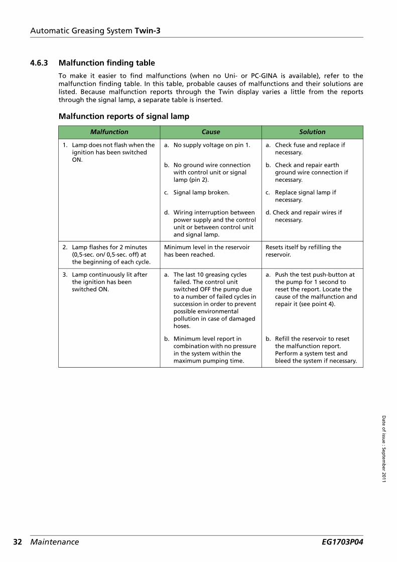
4.6.3 Malfunction finding table
To make it easier to find malfunctions (when no Uni- or PC-GINA is available), refer to themalfunction finding table. In this table, probable causes of malfunctions and their solutions arelisted. Because malfunction reports through the Twin display varies a little from the reportsthrough the signal lamp, a separate table is inserted.
Malfunction reports of signal lamp
Malfunction Cause Solution
1. Lamp does not flash when the ignition has been switched ON.
a. No supply voltage on pin 1. a. Check fuse and replace if necessary.
b. No ground wire connection with control unit or signal lamp (pin 2).
b. Check and repair earth ground wire connection if necessary.
c. Signal lamp broken. c. Replace signal lamp if necessary.
d. Wiring interruption between power supply and the control unit or between control unit and signal lamp.
d. Check and repair wires if necessary.
2. Lamp flashes for 2 minutes (0,5-sec. on/ 0,5-sec. off) at the beginning of each cycle.
Minimum level in the reservoir has been reached.
Resets itself by refilling the reservoir.
3. Lamp continuously lit after the ignition has been switched ON.
a. The last 10 greasing cycles failed. The control unit switched OFF the pump due to a number of failed cycles in succession in order to prevent possible environmental pollution in case of damaged hoses.
a. Push the test push-button at the pump for 1 second to reset the report. Locate the cause of the malfunction and repair it (see point 4).
b. Minimum level report in combination with no pressure in the system within the maximum pumping time.
b. Refill the reservoir to reset the malfunction report. Perform a system test and bleed the system if necessary.
Maintenance EG1703P04

Automatic Greasing System Twin-3
Dat
e o
f is
sue
: Sep
tem
ber
201
1
4. Signal lamp lights continuously for 2 minutes at the end of pumping phase.
The state of the pressure switch did not change from open to closed.Possible causes:
a. The primary grease line leaks. Because of this, no pressure can be built up.
a. Replace or repair the line and vent the relevant line.
b. Air pocket in the system. Within the maximum pumping time insufficient pressure is built up.
b. Vent both primary lines and perform the multiple cycle test twice (See paragraph 3.3).
c. Broken pressure switch. c. See “Procedure to check pressure switch (valve) and its cable” on page 41.
d. O-ring damaged or left out when replacing a metering unit, pressure switch or blind plug, causing grease leakage from line-A to -B and vice versa.
d. Check and mount a new O-ring if necessary. Also see “Procedure when an internal system leak is suspected” on page 43).
e. 5/2-way valve broken, preventing pressure build or release in primary line-A or -B. Because of this, no pressure can be built up or released.
e. See “Procedure to check pump and 5/2-way valve” on page 42.
f. Internal leak of metering unit or pressure switch valve.
f. Replace the metering unit or pressure switch valve.
g. Surrounding temperature too low or grease too viscose.
g. Replace the grease in the reservoir and bleed the system.
h. Wiring defect or bad contacts. h. Check the wiring and contacts. Replace if necessary.
i. Other possible cause. i. Consult the dealer.
ATTENTIONOn request a divergent lamp functionality can be programmed, like:
• inverted lamp functionality (lamp is switched OFF, where normally switched ON).• direct low-level indication on signal lamp (lamp activated for the entire period the level
switch is activated and not only during the pumping phases).
Malfunction Cause Solution
Maintenance 33EG1703P04

34
Date o
f issue : Sep
temb
er 2011
Automatic Greasing System Twin-3
Malfunction reports of Twin-3 display
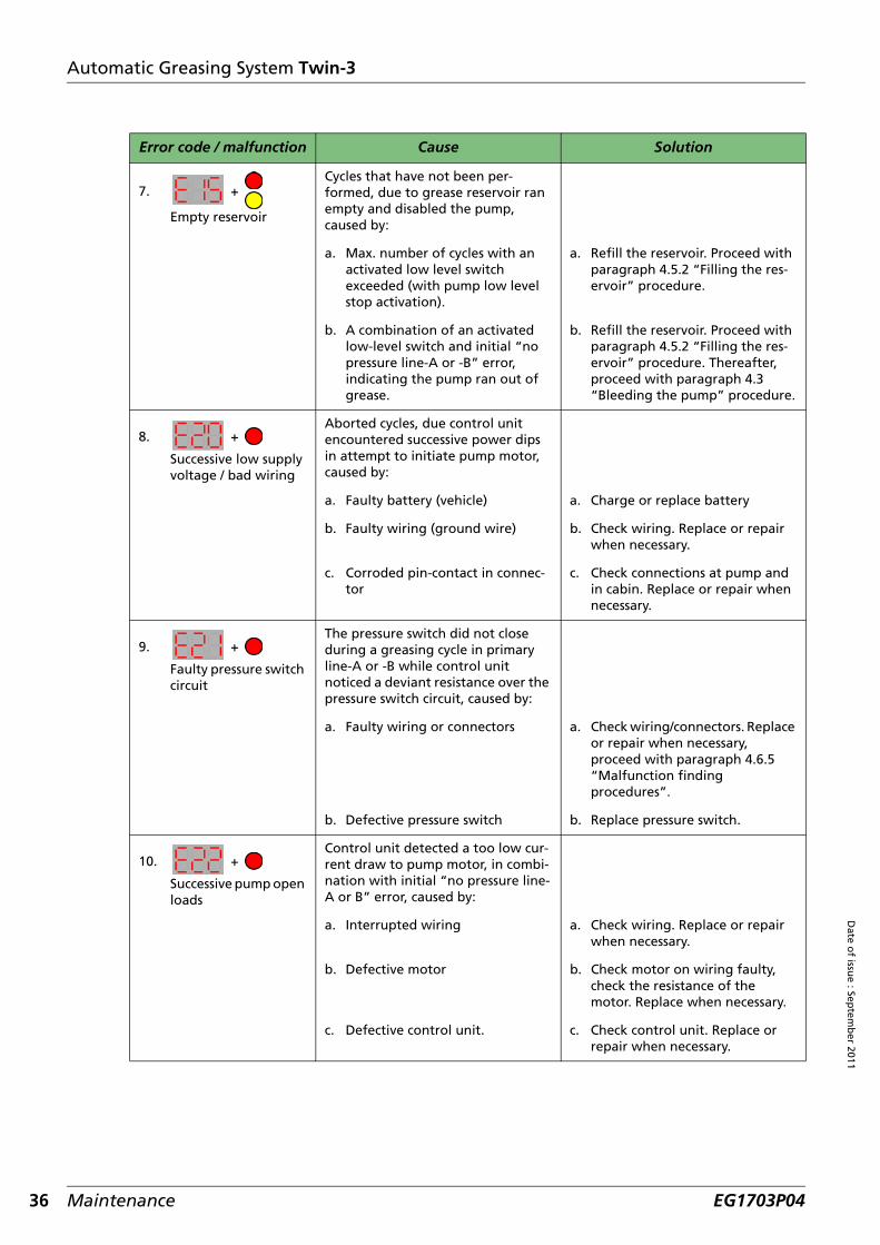
Error code / malfunction Cause Solution
1. One or all LED’s
and/or 3-digit display
, does not
light up partially or completely the moment ignition is switched on.
a. No supply voltage at the display. a. Check fuses and/or wire connec-tion (yellow wire). Repair when necessary.
b. Ground wire disconnected. b. Check the ground wire (brown wire). Repair when necessary.
c. Display does not perform the self test but a single LED or the 3-digit display is broken.
c. Replace display.
d. Defective display d. Replace display.
2.
Decimal DOT is lighted constantly (intervaltimer stop), while it is supposed to run (intervaltimer run).
a. The green command wire no. 3 is stopping the interval timer.
a. Check whether wire no. 3 for stopping the interval timer is connected correctly (see wiring diagram Figure 2.4 and that of the vehicle when available). Repair when necessary.
b. The green command wire no. 3 is stopping the interval timer.
b. Check with the use of an Uni- or PC-GINA whether the timer activation options are set correctly. Change these parameter settings when necessary.
3. +
Successive no pressure in line-A
The pressure switch did not close during a greasing cycle in primary line-A.Possibly caused by:
a. Broken/damaged primary line-A. a. Check condition of primary lines and its connectors. Replace or repair when necessary.
b. Metering unit causes internal by-pass.
b. Proceed with “Procedure when an internal system leak is sus-pected” on page 43.
c. Air trapped into pump and or primary line-A.
c1. Refill reservoir until reservoir is bled. See paragraph 4.5.2 “Filling the reservoir”.
c2. Bleed the pump and primary lines. Proceed with paragraph 4.3 & 4.4 “Bleeding pump & system”.
Maintenance EG1703P04

Automatic Greasing System Twin-3
Dat
e o
f is
sue
: Sep
tem
ber
201
1
4. +
Successive no pressure in line-B
The pressure switch did not close during a greasing cycle in primary line-B.Possibly caused by:
a. Broken/damaged primary line-B. a. Check condition of primary lines and its connectors. Replace or repair when necessary.
b. Metering unit causes internal by pass.
b. Proceed with “Procedure when an internal system leak is sus-pected” on page 43.
c. Air trapped into pump and or primary line-B.
c1. Refill reservoir until reservoir is bled. See paragraph 4.5.2 “Filling the reservoir”.
c2. Bleed the pump and primary lines. Proceed with paragraph 4.3 & 4.4 “Bleeding pump & system”.
5. +
Successive pressure before cycle in line-A
The pressure switch was still closed at the outset of a cycle in primary line-A.Possibly caused by:
a. Damaged PS wiring harness to where wires are joined.
a. Check wiring and connectors. Replace or repair when necessary.
b. 5/2-way valve did not operate correctly.
b. Check 5/2-way valve and operate manually with the use of an Uni- or PC-GINA. Replace or repair when necessary.
c. Pressure switch failed/broken. c. Check and or replace pressure switch (valve).
6. +
Successive pressure before cycle in line-B
The pressure switch was still closed at the outset of a cycle in primary line-B.Possibly caused by:
a. Interrupted PS wiring harness to where wires are joined.
a. Check wiring and connectors. Replace or repair when necessary.
b. 5/2-way valve did not operate correctly.
b. Check 5/2-way valve and operate manually with the use of an Uni- or PC-GINA.Replace or repair when necessary.
c. Pressure switch failed/broken. c. Check and or replace pressure switch (valve).
Error code / malfunction Cause Solution
Maintenance 35EG1703P04
36
Date o
f issue : Sep
temb
er 2011
Automatic Greasing System Twin-3
7. +
Empty reservoir
Cycles that have not been per-formed, due to grease reservoir ran empty and disabled the pump, caused by:
a. Max. number of cycles with an activated low level switch exceeded (with pump low level stop activation).
a. Refill the reservoir. Proceed with paragraph 4.5.2 “Filling the res-ervoir” procedure.
b. A combination of an activated low-level switch and initial “no pressure line-A or -B” error, indicating the pump ran out of grease.
b. Refill the reservoir. Proceed with paragraph 4.5.2 “Filling the res-ervoir” procedure. Thereafter, proceed with paragraph 4.3 “Bleeding the pump” procedure.
8. +
Successive low supply voltage / bad wiring
Aborted cycles, due control unit encountered successive power dips in attempt to initiate pump motor, caused by:
a. Faulty battery (vehicle) a. Charge or replace battery
b. Faulty wiring (ground wire) b. Check wiring. Replace or repair when necessary.
c. Corroded pin-contact in connec-tor
c. Check connections at pump and in cabin. Replace or repair when necessary.
9. +
Faulty pressure switch circuit
The pressure switch did not close during a greasing cycle in primary line-A or -B while control unit noticed a deviant resistance over the pressure switch circuit, caused by:
a. Faulty wiring or connectors a. Check wiring/connectors. Replace or repair when necessary, proceed with paragraph 4.6.5 “Malfunction finding procedures”.
b. Defective pressure switch b. Replace pressure switch.
10. +
Successive pump open loads
Control unit detected a too low cur-rent draw to pump motor, in combi-nation with initial “no pressure line-A or B” error, caused by:
a. Interrupted wiring a. Check wiring. Replace or repair when necessary.
b. Defective motor b. Check motor on wiring faulty, check the resistance of the motor. Replace when necessary.
c. Defective control unit. c. Check control unit. Replace or repair when necessary.
Error code / malfunction Cause Solution
Maintenance EG1703P04

Automatic Greasing System Twin-3
Dat
e o
f is
sue
: Sep
tem
ber
201
1
11. +
Successive pump over current
Control unit detected a too high cur-rent draw to pump motor and aborted the attempted cycle, caused by:
a. Short circuit in wiring of motor a. Check the wiring of motor. Replace or repair when neces-sary.
b. Short circuit in motor. b. Check motor on wiring faulty, check the resistance of the motor. Replace when necessary.
c. Drive shaft blocked c. Check the drive shaft on block-ing. Replace or repair when nec-essary.
d. Extreme low working temperature in combination with a grease not suitable for these conditions.
d. Replace the grease in the reservoir and bleed the system with a suitable grease for the obtained working conditions.
e. The "pump motor current limit" setting not suitable for the extreme low working temperature.
e. Increase the "pump motor current limit" parameter setting but only after checking whether the vehicle wiring and fuse can handle a higher setting.
12. +
Successive valve-1 open loads
Control unit detected a too low current draw to first coil of the5/2-way valve in combination with initial “system on pressure before cycle” error, caused by:
a. Interrupted wiring of the coil a. Check wiring. Replace or repair when necessary.
b. Defective coil b. Check coil on wiring faulty, check the resistance of the coil. Replace or repair when necessary.
13. +
Successive valve-1 over current
Control unit detected a too high cur-rent draw to 5/2-way valve in combi-nation with initial “system on pressure before cycle” error, caused by:
a. Short circuit in wiring of the coil a. Check wiring. Replace or repair when necessary.
b. Defective coil b. Check coil on wiring faulty, check the resistance of the coil. Replace or repair when necessary.
Error code / malfunction Cause Solution
Maintenance 37EG1703P04

38
Date o
f issue : Sep
temb
er 2011
Automatic Greasing System Twin-3
14. +
Successive valve-2 open loads
Control unit detected a too low cur-rent draw to first coil of the 5/2-way valve in combination with initial “system on pressure before cycle” error, caused by:
a. Interrupted wiring of the coil a. Check wiring. Replace or repair when necessary.
b. Defective coil b. Check coil on wiring faulty, check the resistance of the coil. Replace or repair when necessary.
15. +
Successive valve-2 over current
Control unit detected a too high cur-rent draw to 5/2-way valve in combi-nation with initial “system on pressure before cycle” error, caused by:
a. Short circuit in wiring of the coil a. Check wiring. Replace or repair when necessary.
b. Defective coil b. Check coil on wiring faulty, check resistance of the coil. Replace or repair when necessary.
16. +
Communication error with control unit
a. No communication between display & control unit
a. Check the purple communication wire no. 6 between display and pump (pump connector pin no. 6). Repair when necessary.
b. No supply voltage at the pump b. Check the fuse and red power wire no.1 to pump connector no. 1 and the black ground wire no. 2 to the pump connector no. 2. Replace or repair when necessary.
c. Defective Twin-3 display c. When no issues found as stated in solution A or B, replace dis-play.
17. +
Parameter checksum error
Control unit encountered corrupted parameters during power up and restored the production default set-tings.
Replace control unit.
18. +
Low RTC battery (real time clock bat-tery)NOTE: 3V battery
Real time clock battery low(2,2 V) at the control unit.
Replace control unit.
19. +
RTC faulty
Control unit encountered a corrupted real time clock causing the events and errors to be stored with in accurate time & dates caused by:
a. RTC battery empty a. Replace control unit.
Error code / malfunction Cause Solution
Maintenance EG1703P04

Automatic Greasing System Twin-3
Dat
e o
f is
sue
: Sep
tem
ber
201
1
General
Error code / malfunction Cause Solution
20. +
Unknown cause
Control unit encountered an unknown cause due to:
a. Display connected to a Twin-2 control unit (or a Twin-3 control unit with SW version 1063 or lower). Such a control unit does not supply additional info on the cause of the error like the Twin-3 pump does since SW version 1078
a. Replace control unit for one with a SW version 1078 or higher when the additional error information is required.
b. An error cause that is not listed in the table.
b. Replace control unit.
Malfunction Cause Solution
1. All grease points do not receive sufficient grease and no malfunction reports have been given.
a. The set greasing interval is too long for the application.
a. Choose the “heavy duty mode” with the switch-button and or shorten the interval period times in parameter section with the use of an Uni- or PC-GINA.
b. The interval clock does not run (wiring).
b. Check the interval clock command wiring and connection (green wire no. 3 / pump connector pin no. 3).
c. The interval clock does not run (parameter).
c. Check with the use of an Uni- or PC-GINA whether the “timer activation options” are set correctly.
2. All grease points are over greased.
The set greasing interval for the application is too short.
Choose the “low duty mode” with the switch-button and or increase the interval period times in parameter section with the use of an Uni- or PC-GINA.
3. One or more grease points do not show grease while the other points receive sufficient grease.
a. Squeezed or broken secondary grease lines.
a. Check and replace the relevant secondary line if necessary.
b. Metering unit with lesser output then required.
b. Mount metering unit with larger grease output.
c. Metering unit is defect. c. Remove and clean the metering unit or mount a new one.
4. One or more grease points receive excessive amount of grease while the other points do receive the right amount of grease.
a. Metering unit with more output then required.
a. Mount a metering unit with less grease output.
b. Metering unit with internal leak.
b. Remove the metering unit and mount a new one.
Maintenance 39EG1703P04

40
Date o
f issue : Sep
temb
er 2011
Automatic Greasing System Twin-3
4.6.4 Retrieving a fault code message by signal lamp
The fault message that caused the system to malfunction can be retrieved by pushing the dutymode push-button for at least 6 seconds (20-sec. max). Directly after releasing the push button thesignal lamp will show the fault message by flash code (does not function with switch-button ondisplay).
The signal lamp indicates the fault codes by flashing:
- Dozens are shown by long pulses (0,5 seconds)- Units are shown by short pulses (0,15 seconds)
Examples
Code that causes a pump to shut-off
Code that do not cause a pump to shut-off
ATTENTIONFault codes can only be retrieved when the pump communication line (pin/wire no. 6) is notconnected to an Uni- or PC-GINA and need to be disconnected for at least 50 seconds before a codecan be retrieved.
Pulse Fault code
long, short, short, short, short 14
long, long, short 21
Fault code Meaning
11 No pressure line-A
12 No pressure line-B
13 Pressure before cycle in line-A
14 Pressure before cycle in line-B
15 Empty grease reservoir
20 Low supply voltage or bad wiring
21 Pressure switch circuit error
22 Open load pump circuit
23 Over current pump circuit
24 Open load valve 1
25 Over current valve 1
31 Open load valve 2
32 Over current valve 2
99 An error cause, not listed in the table / Replace control unit.
Fault code Meaning
10 Currently no errors available
51 Parameter checksum error
52 Clock battery low
53 Clock error
Maintenance EG1703P04

Automatic Greasing System Twin-3
Dat
e o
f is
sue
: Sep
tem
ber
201
1
4.6.5 Malfunction finding procedures
A number of procedures to determine the correct cause of a certain malfunction are describedbelow.
Procedure to check pressure switch (valve) and its cable
1. Disconnect the 2-pole connector from the pressure switch.2. Measure the resistance between the two contacts using a digital multimeter. When the sys-
tem is pressureless , the resistance should be 22K ohm. If required, remove the switch to make sure that no pressure below the pressure switch is present. Remove only the upper part, the diverter valve can be left in place.
3. If possible, mount a pressure gauge that is suitable for a grease pressure up to 250 bar between the diverter valve and the pressure switch and bleed this connection before use.
4. Switch ignition ON.5. Start a cycle test by pushing the test push-button at the pump.6. Check the switching moment of the pressure switch using the digital multi-meter. When the
adjusted pressure (see the side of the pressure switch) is reached the contact should be closed, the resistance should ± 0 ohm.
7. Switch ignition OFF for ending the cycle test.
If the pressure switch functions properly, the cable should be checked for internal damage.
8. Connect both contacts of the connector of the pressure switch with a separate wire.9. Disconnect the pump connector.10. Measure the resistance between pin 7 and 8 of the pump connector. The measured resistance
should be ± 0 ohm.11. Remove the wire between the contacts of the connector of the pressure switch. The digital
multimeter should read an open load.
ATTENTIONIf a pressure switch without a resistor is being used in the greasing system you should measure anopen load.
Maintenance 41EG1703P04

42
Date o
f issue : Sep
temb
er 2011
Automatic Greasing System Twin-3
Procedure to check pump and 5/2-way valve
1. Disconnect both primary grease lines from the pump outlet A and B.
2. Connect a pressure gauge to each channel of the pump. Use pressure gauges that are suitable for a grease pressure of 250 bar.
3. Switch ignition ON.4. Push the test push-button at the pump for about 4 seconds to start a cycle test.
The pump now pumps grease from one of the channels. The pressure reading of the gauge connected to this channel should raise to the maximum attainable pressure of 230 to 250 bar.
If the pump does not reach the indicated pressure, it has the following causes:
• Air lock in the grease (air bubbles). Disconnect the pressure gauge and let the grease flowuntil no more air bubbles come from the channel. If necessary, refill the reservoir with someoil to remove the air around the pumping element.
• Temperature too low and or grease is too viscous. Therefore it is not sucked in by thepumping piston. Replace the grease in the reservoir and the primary grease lines by moresuitable grease for the aimed temperature.
• Pump is faulty. Replace the pump.
5. End the cycle test by switching the ignition OFF or by disconnecting the pump connector for a moment.
6. Switch ignition ON.7. Start another cycle test with the test push-button at the pump;
The pump should start in the other channel and the pressure gauge will quickly increase to the maximum adjusted grease pressure of 230 to 250 bar. The first channel should become de-pressurised.
When the pressure in the first channel does not drop and no pressure is built up in the otherchannel, the 5/2-way valve is faulty. Replace the valve or the entire pump.
8. End the cycle test by switching of the ignition or by disconnecting the pump connector for a moment.
WARNING
Check whether the system is pressureless before the system is opened!
ATTENTION
The pump is not switched OFF by the pressure switch, because the greasing system is disconnected.
Maintenance EG1703P04

Automatic Greasing System Twin-3
Dat
e o
f is
sue
: Sep
tem
ber
201
1
Procedure when an internal system leak is suspected
1. Disconnect the primary grease line of outlet B of the pump.
2. Switch ignition ON.3. Push the test push-button at the pump for about 4 seconds to start a cycle test.
The pump is started and pumps grease through one of the grease channels. If this is not chan-nel A, break off the cycle test by switching the ignition OFF or by momentarily disconnecting the pump connector. Start another cycle test with the test push-button at the pump. The pump starts automatically in the other channel (A).
While the pressure in channel A builds up, some returning grease can come from the justdisconnected grease line. However when grease keeps flowing from this line there is an openconnection between both primary grease channels, most likely caused by a missing or damaged O-ring under one (or more) metering unit(s).
When a leak is established in the system, it has to be determined in which distribution block theleak is present.
4. Disconnect the primary grease line from block channel B, directly after the first distribution block after the pump.
5. Restart the pump in channel A.
When the grease leaks from outlet B of this first distribution block, the leak must be found in thisblock. When the grease leaks from the disconnected primary grease line, the leak must be soughtfarther down the system. Therefore repeat this procedure every time using the next distributionblock until the leak is found.
When there is only little leak, it may be impossible to establish the leak with the operating pump.Therefore, switch OFF the pump when the maximum pressure is reached. Switch ignition OFF ormomentarily disconnect the pump connector. The pressure should be steady (minimum 200 bar; thisprocedure only works for channel A). The pressure may only drop when the control unit opens thevalve, as soon as a new cycle test is started in channel B.
When there is a pressure drop, but there is no grease coming back, it indicates a leaking meteringunit. Therefore check all connected grease points on an excessive grease collar indicating aninternal leakage.
WARNING
Check whether the system is pressureless before the system is opened!
NOTETo determine which distribution block channel is connected to pump outlet A, you need to followthe primary grease line to the pump.
Maintenance 43EG1703P04
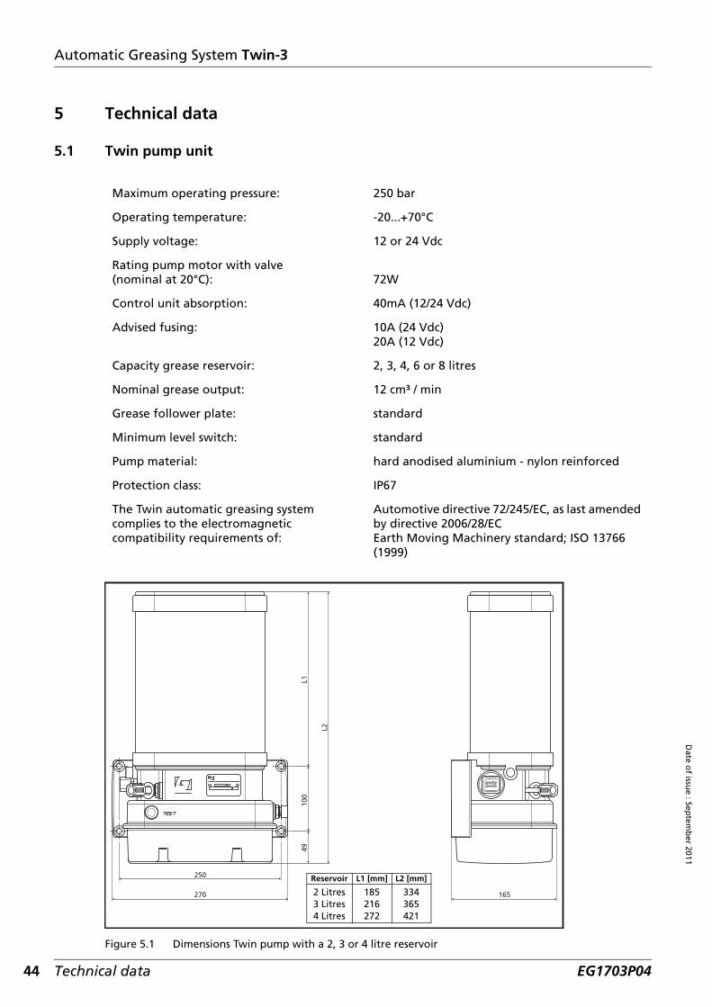
44
Date o
f issue : Sep
temb
er 2011
Automatic Greasing System Twin-3
5 Technical data
5.1 Twin pump unit
Figure 5.1 Dimensions Twin pump with a 2, 3 or 4 litre reservoir
Maximum operating pressure: 250 bar
Operating temperature: -20...+70°C
Supply voltage: 12 or 24 Vdc
Rating pump motor with valve(nominal at 20°C): 72W
Control unit absorption: 40mA (12/24 Vdc)
Advised fusing: 10A (24 Vdc)20A (12 Vdc)
Capacity grease reservoir: 2, 3, 4, 6 or 8 litres
Nominal grease output: 12 cm³ / min
Grease follower plate: standard
Minimum level switch: standard
Pump material: hard anodised aluminium - nylon reinforced
Protection class: IP67
The Twin automatic greasing system complies to the electromagnetic compatibility requirements of:
Automotive directive 72/245/EC, as last amended by directive 2006/28/ECEarth Moving Machinery standard; ISO 13766 (1999)
250
270 165
4910
0L1
L2
L1 [mm]
185216272
Reservoir
2 Litres3 Litres4 Litres
L2 [mm]
334365421
Technical data EG1703P04

Automatic Greasing System Twin-3
Dat
e o
f is
sue
: Sep
tem
ber
201
1
Figure 5.2 Dimensions Twin pump with a 6 or 8 litre reservoir
5.2 Signal lamp
Max. allowed power consumption: 3W
250
270 162
4910
0L1
L2
L1 [mm]
326415
Reservoir
6 Litres8 Litres
L2 [mm]
475564
Technical data 45EG1703P04

46
Date o
f issue : Sep
temb
er 2011
Automatic Greasing System Twin-3
5.3 Twin display
Figure 5.3 Dimensions of the Twin display
Regulations / EMC
Off road ISO 13766-2006
Road transport 2004/104/EC
Industrial equipment 2004/108/EC
Environment
Ambient operating temperature range: -25…+70 °C
Storage temperature range: -25…+70 °C
Casing humidity/dust: IP54
Electrical
Supply operating voltage range: 9…32 VDC
Max. operating current: 220 mA
Open drain outputs max current: 250 mA
Open drain max voltage: 32 VDC
Cable length max: 5 meter
TWIN
AutomaticGreasingSystem
SWITCH
18.2
32.1
4.0
29.0
23.0
23
.0
70.0
116.
0
Technical data EG1703P04


Groeneveld Transport Efficiency B.V., Stephensonweg 12, 4207 HB Gorinchem, P.O. Box 777, 4200 AT Gorinchem, The Netherlands, Ph : +31 183 641 400, F : +31 183 624 474, http://www.groeneveld-group.com
www.groeneveld-group.com