live crude oil volatility...api/astm manual piston cylinder sampling practice currently on d02 main...
TRANSCRIPT

Live Crude Oil Volatility
Dan Wispinski : Alberta Innovates – Technology Futures
Bob Falkiner : Imperial Oil Engineering Services October 16/15 PerkinElmer – Corpus Christi

Any and all implied or statutory warranties of merchantability or fitness for any purpose are expressly excluded. The reader acknowledges that any use or
interpretation of the information, analysis or conclusions contained in this presentation is at its own risk. Reference herein to any specified commercial
product, process or service by trade-name, trademark, manufacturer or otherwise does not constitute or imply an endorsement or recommendation by AITF.

Vapour Pressure
Light Ends Determination by GC
ASTM Definition for Live Crude
Live crude oil,n — crude oil with sufficiently high vapour pressure that it would boil if exposed to normal atmospheric pressure at room temperature.
Discussion - Sampling and handling of live crude oils requires a pressurized sample system and pressurized sample containers to ensure sample integrity and prevent loss of volatile components.

Need – no method for Live Crude Oil
ASTM D7169 HTSD Crude sample is diluted with CS2 @ ambient
temperature & pressure Light ends lost Light ends not reported Light ends are quenched by CS2

Need – no method for Live Crude Oil
ASTM D7900 Merge Internal Standard is added to crude sample at
ambient Temperature & Pressure Light ends lost Light ends are reported (usually to nC10 DHA)
and remainder of crude is backflushed Data is then used to correct CS2 quenching in
distillation curve by mathematically “merging” with D7169

Need – no method for Live Crude Oil
ASTM D7900 / ASTM D7169 Samples are collected under atmospheric
conditions Use of sealed sample collection cylinders not
mentioned
Sampling
Sealed container (D3700 FPC) or D1265 cylinder required API/ASTM also working on MPC

Safety & Economic Drivers Transportation Rail cars
Crude Oil Valuation Custody transfer Refinery impacts Compliance
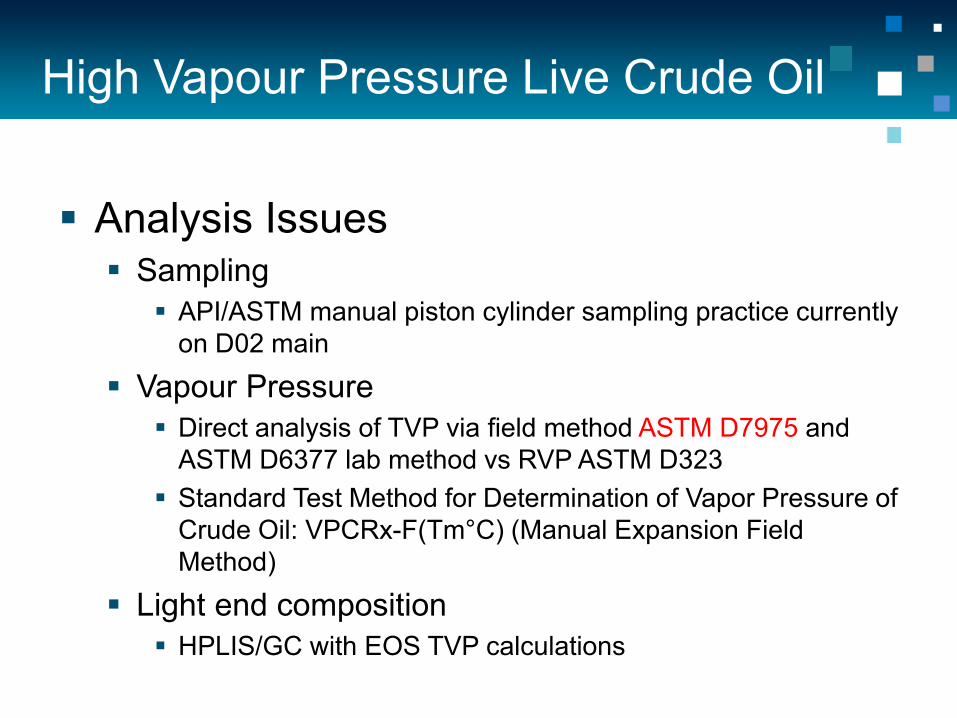
High Vapour Pressure Live Crude Oil Analysis Issues Sampling
API/ASTM manual piston cylinder sampling practice currently on D02 main
Vapour Pressure Direct analysis of TVP via field method ASTM D7975 and
ASTM D6377 lab method vs RVP ASTM D323 Standard Test Method for Determination of Vapor Pressure of
Crude Oil: VPCRx-F(Tm°C) (Manual Expansion Field Method)
Light end composition HPLIS/GC with EOS TVP calculations
Sampling
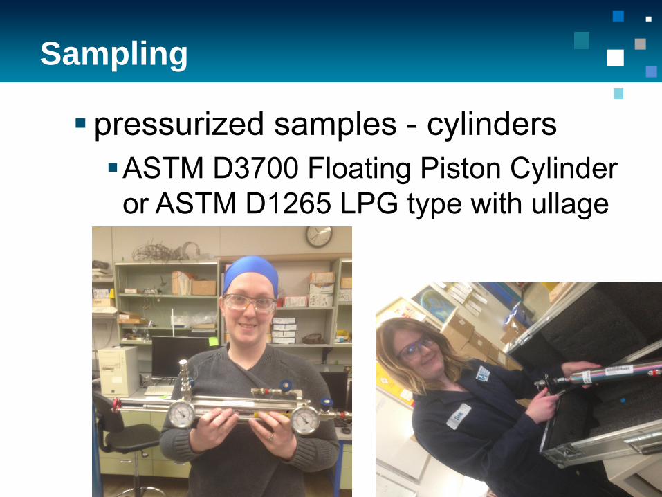
pressurized samples - cylinders ASTM D3700 Floating Piston Cylinder
or ASTM D1265 LPG type with ullage tube

ASTM D8003 Scope
This test method covers the determination of light hydrocarbons and cut point intervals via gas chromatography in live crude oils and condensates with VPCR4 up to 500 kPa at 37.8 °C as described in Test Method D6377
Methane (nC1) to hexane (nC6) including iC5, benzene, and benzene precursors are speciated and quantitated.

HPLIS Method Summary ■ Liquid sample valve connected to
pressurized sample ■ Theoretical mass response factors ■ Cut point fractions – generalized physical
properties ■ External std calibration with density
correction – determination of residue – similar to RGO in D7169
■ Primary purpose is light end quant – BP distribution can be determined
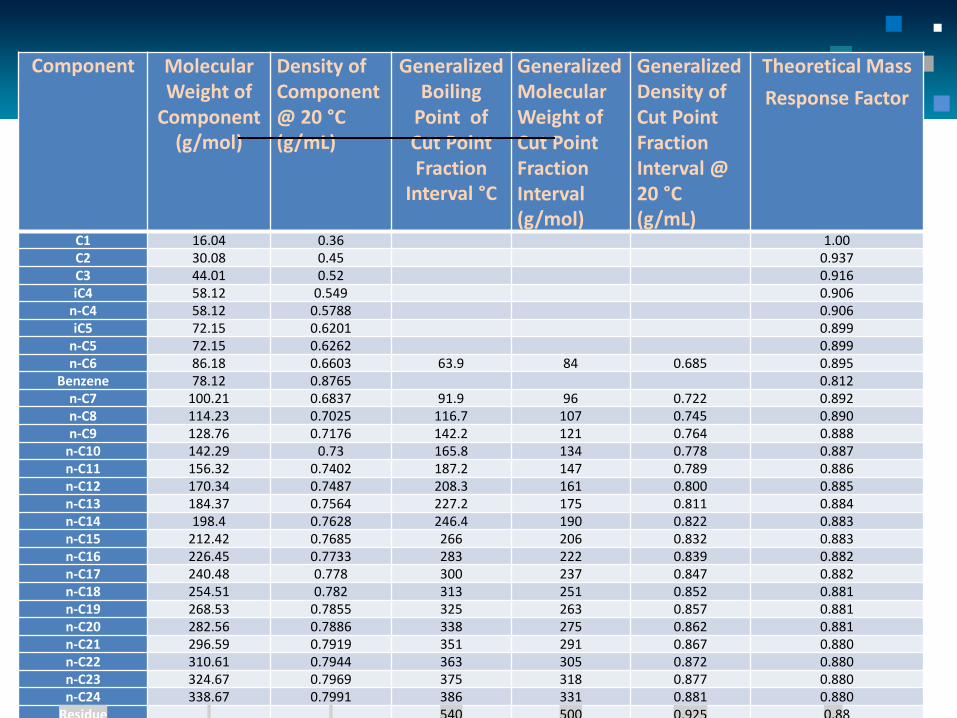
Component Molecular Weight of
Component (g/mol)
Density of Component @ 20 °C (g/mL)
Generalized Boiling
Point of Cut Point Fraction
Interval °C
Generalized Molecular Weight of Cut Point Fraction Interval (g/mol)
Generalized Density of Cut Point Fraction Interval @ 20 °C (g/mL)
Theoretical Mass Response Factor
C1 16.04 0.36 1.00 C2 30.08 0.45 0.937 C3 44.01 0.52 0.916 iC4 58.12 0.549 0.906
n-C4 58.12 0.5788 0.906 iC5 72.15 0.6201 0.899
n-C5 72.15 0.6262 0.899 n-C6 86.18 0.6603 63.9 84 0.685 0.895
Benzene 78.12 0.8765 0.812 n-C7 100.21 0.6837 91.9 96 0.722 0.892 n-C8 114.23 0.7025 116.7 107 0.745 0.890 n-C9 128.76 0.7176 142.2 121 0.764 0.888
n-C10 142.29 0.73 165.8 134 0.778 0.887 n-C11 156.32 0.7402 187.2 147 0.789 0.886 n-C12 170.34 0.7487 208.3 161 0.800 0.885 n-C13 184.37 0.7564 227.2 175 0.811 0.884 n-C14 198.4 0.7628 246.4 190 0.822 0.883 n-C15 212.42 0.7685 266 206 0.832 0.883 n-C16 226.45 0.7733 283 222 0.839 0.882 n-C17 240.48 0.778 300 237 0.847 0.882 n-C18 254.51 0.782 313 251 0.852 0.881 n-C19 268.53 0.7855 325 263 0.857 0.881 n-C20 282.56 0.7886 338 275 0.862 0.881 n-C21 296.59 0.7919 351 291 0.867 0.880 n-C22 310.61 0.7944 363 305 0.872 0.880 n-C23 324.67 0.7969 375 318 0.877 0.880 n-C24 338.67 0.7991 386 331 0.881 0.880
Residue 540 500 0.925
0.88
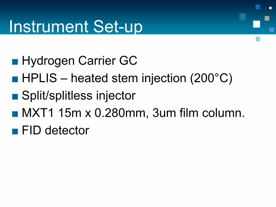
Instrument Set-up
■ Hydrogen Carrier GC ■ HPLIS – heated stem injection (200°C) ■ Split/splitless injector ■ MXT1 15m x 0.280mm, 3um film column. ■ FID detector

HPLIS valve on GC
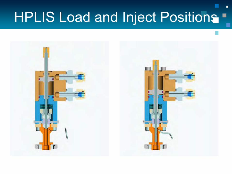
HPLIS Load and Inject Positions

Heated STEM of HPLIS
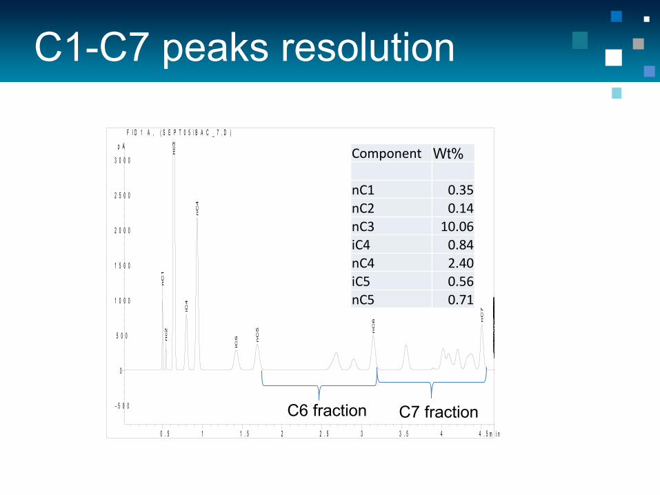
C1-C7 peaks resolution
m i n0 . 5 1 1 . 5 2 2 . 5 3 3 . 5 4 4 . 5
p A
- 5 0 0
0
5 0 0
1 0 0 0
1 5 0 0
2 0 0 0
2 5 0 0
3 0 0 0
F I D 1 A , ( S E P T 0 5 \ B A C _ 7 . D )
nC
1 n
c2
nc3
iC
4
nC
4
iC
5
nC
5
nC
6 nC
7
nC
8 n
C9
nC
10
nC
11
nC
12
nC
13
nc1
4 n
C1
5 n
C1
6 n
C1
7 n
C1
8 n
C1
9 n
C2
0 n
C2
1 n
C2
2 n
C2
3 n
C2
4 n
C2
5 n
C2
6 n
C2
7 n
C2
8 n
C2
9 n
C3
0 n
C3
1 n
C3
2 n
C3
3 n
C3
4
Component Wt% nC1 0.35 nC2 0.14 nC3 10.06 iC4 0.84 nC4 2.40 iC5 0.56 nC5 0.71
C7 fraction C6 fraction
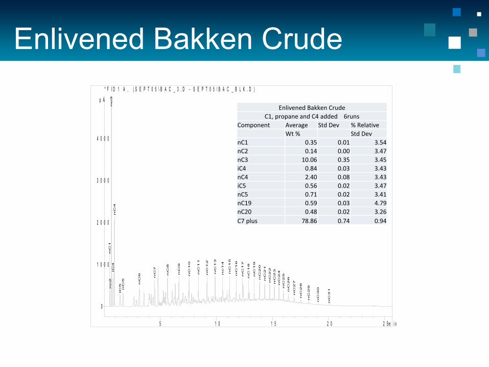
Enlivened Bakken Crude
m i n5 1 0 1 5 2 0 2 5
p A
0
1 0 0 0
2 0 0 0
3 0 0 0
4 0 0 0
* F I D 1 A , ( S E P T 0 5 \ B A C _ 3 . D - S E P T 0 5 \ B A C _ B L K . D )
nC
1 n
c2
nc3
iC
4 n
C4
iC
5 n
C5
nC
6
nC
7
nC
8
nC
9
nC
10
nC
11
nC
12
nC
13
nc1
4
nC
15
nC
16
nC
17
nC
18
nC
19
nC
20
nC
21
nC
22
nC
23
nC
24
nC
25
nC
26
nC
27
nC
28
nC
29
nC
30
nC
31
Enlivened Bakken Crude C1, propane and C4 added 6runs
Component Average Std Dev % Relative Wt % Std Dev nC1 0.35 0.01 3.54 nC2 0.14 0.00 3.47 nC3 10.06 0.35 3.45 iC4 0.84 0.03 3.43 nC4 2.40 0.08 3.43 iC5 0.56 0.02 3.47 nC5 0.71 0.02 3.41 nC19 0.59 0.03 4.79 nC20 0.48 0.02 3.26 C7 plus 78.86 0.74 0.94
Calibration Standards
Gasoline/Jet A1mix spiked with methane, ethane, and n-paraffin's betweenC16 and C24. Seven D1265 cylinders were made and run
multiple times on the HPLIS to get precision data, and verify the ability to make homogeneous samples in cylinders of this type.

Average, mass% StdDev Max Min r estimate %RSD
Methane 0.156 0.0075 0.175 0.137 0.0208 4.8 Ethane 0.546 0.0179 0.585 0.478 0.0496 3.3 Propane 0.002 0.0001 0.002 0.002 0.0003 4.6 Isobutane 0.448 0.0103 0.458 0.404 0.0285 2.3 Butane 2.769 0.0588 2.829 2.515 0.1629 2.1 C4+ to C17- 95.759 0.0893 96.134 95.633 0.2474 0.1 c17 0.063 0.0006 0.064 0.062 0.0017 1.0 c18 0.050 0.0005 0.051 0.049 0.0014 1.0 c19 0.058 0.0006 0.059 0.057 0.0017 1.0 c20 0.055 0.0007 0.057 0.054 0.0019 1.2 c22 0.052 0.0010 0.055 0.051 0.0028 2.0 c24 0.041 0.0019 0.047 0.038 0.0053 4.7 TOTAL AREA 210094 5286 222713 203066 2.5
Calibration Standard 7 cylinders -24 runs

min5 10 15 20 25
Norm.
0
500
1000
1500
2000
2500
3000
FID1 A, (FL_SAMPLES\HPLIS STD FL14-1065 2014-09-08 08-10-55\FL14-1065-002.D)
Me
tha
ne
Eth
an
e P
ro
pa
ne
iso
bu
tan
e b
uta
ne
Iso
pe
nta
ne
pe
nta
ne
he
xa
ne
C7
C8
C9
C1
0
C1
1
C1
2
C1
3
C1
4
C1
5
C1
6
C1
7
C1
9
C2
0
C2
2
C2
4
Calibration Standard

Validation standards – accumulator (FPC)
Five samples prepared from a dead oil, with different target mass% concentrations of light ends.
C1 C2 C3 iC4 nC4 iC5 nC5 nC6
Sample VP (kPa) at 4:1 Vapour-to-liquid volume ratio at 37.8°C
Sample 1 High 0.25 0.75 0.5 0 0 1 5 8 174 Sample 2 Typical 0.05 0.25 1.5 0 3.7 1 2.9 4 128.7 Sample 3 typical repeat 0.05 0.25 1.5 0 3.7 1 2.9 4 128.7
Sample 4 typical high c1,c2,c3 0.1 0.5 3 0 0 1 2.9 4 183.7
Sample 5 Low sample 0.05 0.075 0 0 15 0 0 0 Not calculated
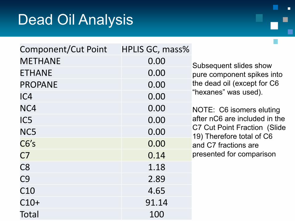
Dead Oil Analysis
Component/Cut Point HPLIS GC, mass% METHANE 0.00 ETHANE 0.00 PROPANE 0.00 IC4 0.00 NC4 0.00 IC5 0.00 NC5 0.00 C6’s 0.00 C7 0.14 C8 1.18 C9 2.89 C10 4.65 C10+ 91.14 Total 100
Subsequent slides show pure component spikes into the dead oil (except for C6 “hexanes” was used). NOTE: C6 isomers eluting after nC6 are included in the C7 Cut Point Fraction (Slide 19) Therefore total of C6 and C7 fractions are presented for comparison
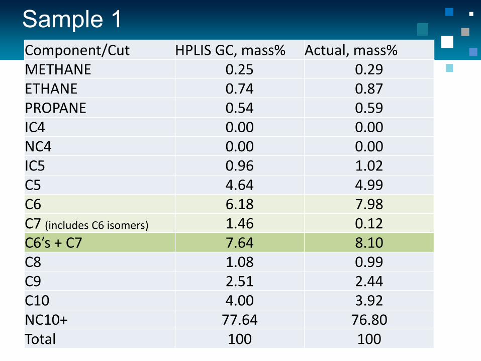
Sample 1 Component/Cut HPLIS GC, mass% Actual, mass% METHANE 0.25 0.29 ETHANE 0.74 0.87 PROPANE 0.54 0.59 IC4 0.00 0.00 NC4 0.00 0.00 IC5 0.96 1.02 C5 4.64 4.99 C6 6.18 7.98 C7 (includes C6 isomers) 1.46 0.12 C6’s + C7 7.64 8.10 C8 1.08 0.99 C9 2.51 2.44 C10 4.00 3.92 NC10+ 77.64 76.80 Total 100 100
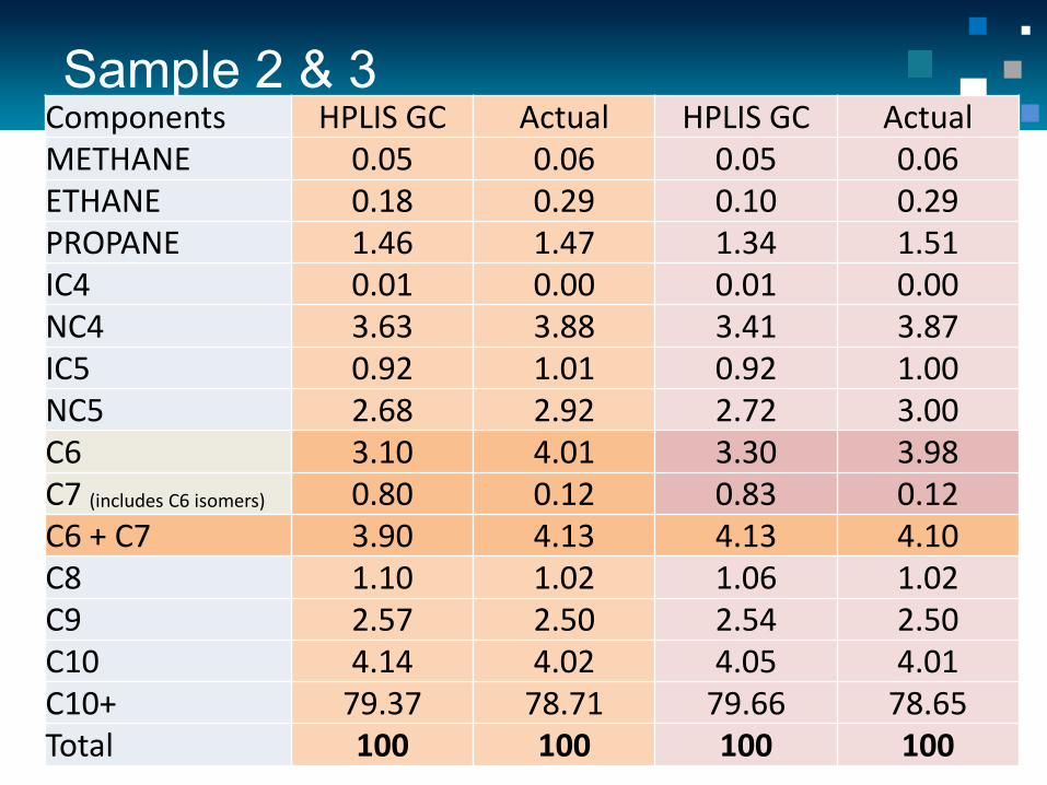
Sample 2 & 3 Components HPLIS GC Actual HPLIS GC Actual METHANE 0.05 0.06 0.05 0.06 ETHANE 0.18 0.29 0.10 0.29 PROPANE 1.46 1.47 1.34 1.51 IC4 0.01 0.00 0.01 0.00 NC4 3.63 3.88 3.41 3.87 IC5 0.92 1.01 0.92 1.00 NC5 2.68 2.92 2.72 3.00 C6 3.10 4.01 3.30 3.98 C7 (includes C6 isomers) 0.80 0.12 0.83 0.12 C6 + C7 3.90 4.13 4.13 4.10 C8 1.10 1.02 1.06 1.02 C9 2.57 2.50 2.54 2.50 C10 4.14 4.02 4.05 4.01 C10+ 79.37 78.71 79.66 78.65 Total 100 100 100 100

Sample 4 Component/Cut HPLIS GC, mass% Actual, mass% METHANE 0.10 0.11 ETHANE 0.52 0.58 PROPANE 2.87 3.04 IC4 0.01 0.00 NC4 0.00 0.00 IC5 0.95 1.00 NC5 2.68 2.91 C6 3.13 3.98 C7 (includes C6 isomers) 0.80 0.12 C6 + C7 3.93 4.10 C8 1.12 1.04 C9 2.63 2.56 C10 4.28 4.11 C10+ 80.90 80.55 Total 100 100

Sample 5
Component/Cut HPLIS GC, mass% Actual, mass% METHANE 0.05 0.06 ETHANE 0.09 0.09 PROPANE 0.00 0.00 IC4 0.02 0.00 NC4 14.10 15.05 IC5 0.02 0.00 NC5 0.00 0.00 C6 0.00 0.00 C7 (includes C6 isomers) 0.13 0.12 C8 1.04 1.00 C9 2.54 2.45 C10 4.09 3.94 C10+ 77.92 77.29 Total 100.0 100.0

EOS SRK Modeling of Binary Mixtures
0
10
20
30
40
50
60
70
80
90
100
0 0.5 1 1.5 2 2.5 3 3.5 4 4.5
Pres
sure
, kPa
Volume Ratio, V/Linitial
AIR
Methane
Ethane
Propane
Butane
Calculated VP of gases in isooctane, 37.8C

Experimental Values

Reuters News Article

Binary Mixtures
Air has profound effect on VPCR at low VL ratios Air and methane have similar effect/curves

Gas Oil Ratio Determination
The ratio of the volume of gas to the volume of oil at standard conditions. Primarily used in reservoir modeling or in production monitoring. AITF developing miniaturized apparatus to determine CO2, CO, H2S, H2, O2 & N2

Gas Oil Ratio Determination Sample # C1
HPLIS GOR
1 0.007 0.005
2 0.000 0.006
3 0.017 0.016
4 0.005 0.004
5 0.012 0.010
6 0.004 0.005
7 0.012 0.008
8 0.014 0.007
9 0.039 0.025
10 0.023 0.022
11 0.006 0.005
12 0.011 0.007
13 0.014 0.010
14 0.006 0.006
15 0.024 0.023
16 0.033 0.045
HPLIS vs GOR Methane on 16 Various Crude samples
Thank you
AITF Chris Goss, Trevor Lockyer, Deepyaman Seth CCQTA, ASTM Bob Falkiner Imperial Oil Engineering Services [email protected]
Dan Wispinski Alberta Innovates [email protected]