linear servo drive linear sigma series - motortong.com · linear servo drive series ... magnetic...
TRANSCRIPT
LITERATURE NO. KAE-S800-39.10
LINEAR SERVO DRIVE
SERIESLINEAR SERVOMOTOR TYPE
SERVO DRIVER(SERVOPACK)TYPE
CORELESS GW:SGLGWIRON-CORE FW:SGLFWIRON-CORE TW:SGLTW :SGDH
Linear
YASKAWA
JQA-EM0202JQA-EM0924
JQA-0422
Certified forISO9001 andISO14001
Performances
Constructions and Features
Range of Products
Type Designations
Coreless GW (U-Channel types)
Iron-core FW (Flat-bed types)
Iron-core TW (See photo below)
SGDH
4
6
8
9
10
14
22
30
34
36
Page
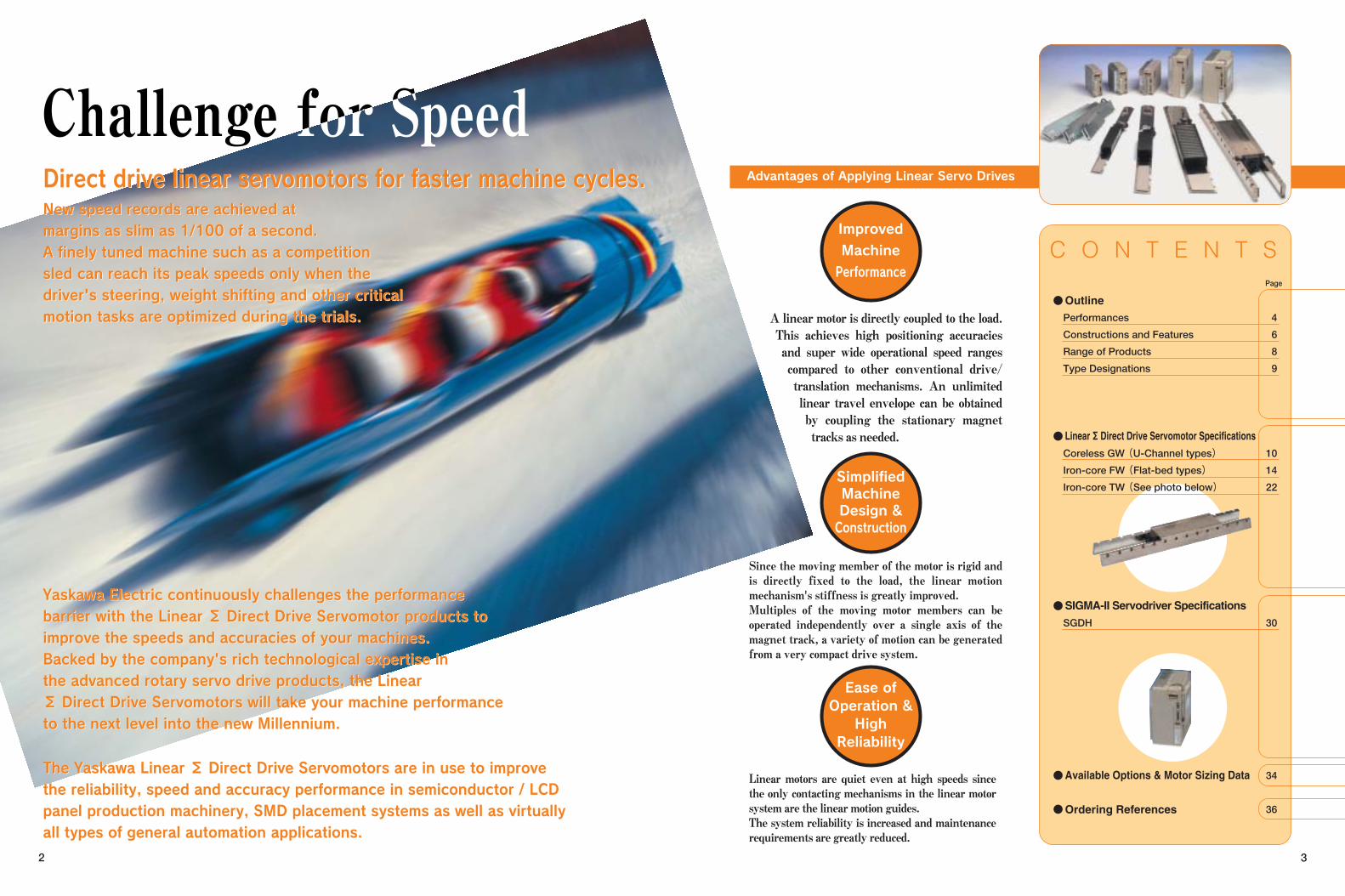
Linear motors are quiet even at high speeds since the only contacting mechanisms in the linear motor system are the linear motion guides. The system reliability is increased and maintenance requirements are greatly reduced.
Since the moving member of the motor is rigid and is directly fixed to the load, the linear motion mechanism's stiffness is greatly improved. Multiples of the moving motor members can be operated independently over a single axis of the magnet track, a variety of motion can be generated from a very compact drive system.
2 3
A linear motor is directly coupled to the load. This achieves high positioning accuracies and super wide operational speed ranges compared to other conventional drive/ translation mechanisms. An unlimited linear travel envelope can be obtained by coupling the stationary magnet tracks as needed.
Direct drive linear servomotors for faster machine cycles.Direct drive linear servomotors for faster machine cycles.New speed records are achieved atmargins as slim as 1/100 of a second.A finely tuned machine such as a competitionsled can reach its peak speeds only when thedriver's steering, weight shifting and other criticalmotion tasks are optimized during the trials.
Yaskawa Electric continuously challenges the performancebarrier with the Linear Σ Direct Drive Servomotor products toimprove the speeds and accuracies of your machines.Backed by the company's rich technological expertise inthe advanced rotary servo drive products, the LinearΣ Direct Drive Servomotors will take your machine performanceto the next level into the new Millennium.
The Yaskawa Linear Σ Direct Drive Servomotors are in use to improvethe reliability, speed and accuracy performance in semiconductor / LCDpanel production machinery, SMD placement systems as well as virtuallyall types of general automation applications.
Advantages of Applying Linear Servo Drives
Improved
Machine
Performance
SimplifiedMachineDesign &Construction
Ease ofOperation &High
Reliability
Outline
Linear Σ Direct Drive Servomotor Specifications
SIGMA-II Servodriver Specifications
Available Options & Motor Sizing Data
Ordering References
New speed records are achieved atmargins as slim as 1/100 of a second.A finely tuned machine such as a competitionsled can reach its peak speeds only when thedriver's steering, weight shifting and other criticalmotion tasks are optimized during the trials.
4
Force Density
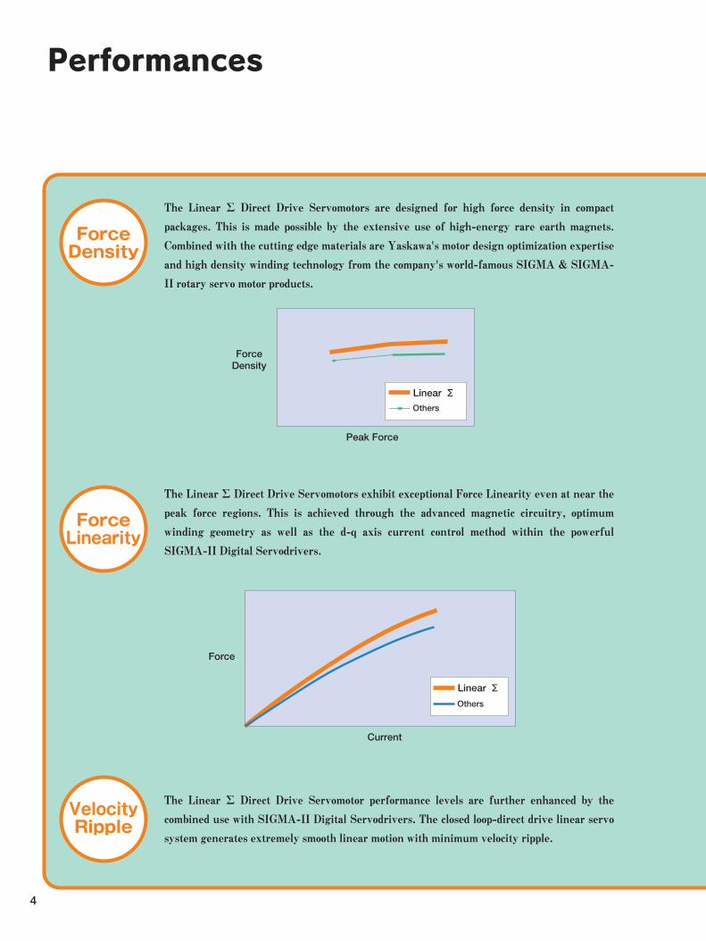
The Linear Σ Direct Drive Servomotors are designed for high force density in compact
packages. This is made possible by the extensive use of high-energy rare earth magnets.
Combined with the cutting edge materials are Yaskawa's motor design optimization expertise
and high density winding technology from the company's world-famous SIGMA & SIGMA-
II rotary servo motor products.
Force Linearity
The Linear Σ Direct Drive Servomotors exhibit exceptional Force Linearity even at near the
peak force regions. This is achieved through the advanced magnetic circuitry, optimum
winding geometry as well as the d-q axis current control method within the powerful
SIGMA-II Digital Servodrivers.
Velocity Ripple
The Linear Σ Direct Drive Servomotor performance levels are further enhanced by the
combined use with SIGMA-II Digital Servodrivers. The closed loop-direct drive linear servo
system generates extremely smooth linear motion with minimum velocity ripple.
Force Density
Peak Force
Linear Σ Others
Current
Force
Linear Σ
Others
Performances
Speed
Acceleration
Settling Time
Magnetic Attraction Forces
High Efficiency
The Linear Σ Direct Drive Servomotors can reach speeds as high as 5 meters (196 inches)
per second. Since the direct drive linear motors do not suffer from the usual limitations of
the conventional mechanical drive systems, the operational speed ranges are not constrained
by factors such as the travel lengths of the linear motion systems.
The Linear Σ Direct Drive Servomotors can accelerate well beyond the capability of other
mechanical linear translation systems.
The Linear Σ motors themselves can reach astonishing 20Gs of maximum acceleration.
The Linear Σ Direct Drive Servomotors combined with the SIGMA-II Servodrivers can
shorten the system settling time after motion. The excellent dynamic stiffness of the Linear
Σ motors and one of the fastest servodriver in the industry can immediately improve your
machines' motion cycle specifications.
The Linear Σ Direct Drive Servomotors are extremely energy efficient. Due to its optimized
magnetic circuitry design and high-density windings inherited from the company's
legendary SIGMA Servomotors, the effects of motors' heat being transferred to the other
areas of your machine are minimized.
The Linear Σ Type GW motors are Coreless and there is no attraction force between the
motor members, and is of Zero-Cogging in nature.
The Linear Σ Type FW and TW motors are Iron-core type, and there are small to large
attraction forces, depending on the size of the motor, between the moving and the stationary
parts of the motors. These attraction forces can provide benefits in some systems by
providing the Preload Forces to the Linear Motion Guides, increasing the system rigidity.
Inversely, the attraction forces may negatively affect the mechanical design freedom since
the forces acting on the relative members of the motors must be properly supported by
increased bearing load capacities.
The Iron-core TW motors overcome this limitation in the Iron-core design by a patented
structure where the attraction forces are negated by its unique layout. The TW motors offer
the high force density and long linear bearing life in compact packages.
5
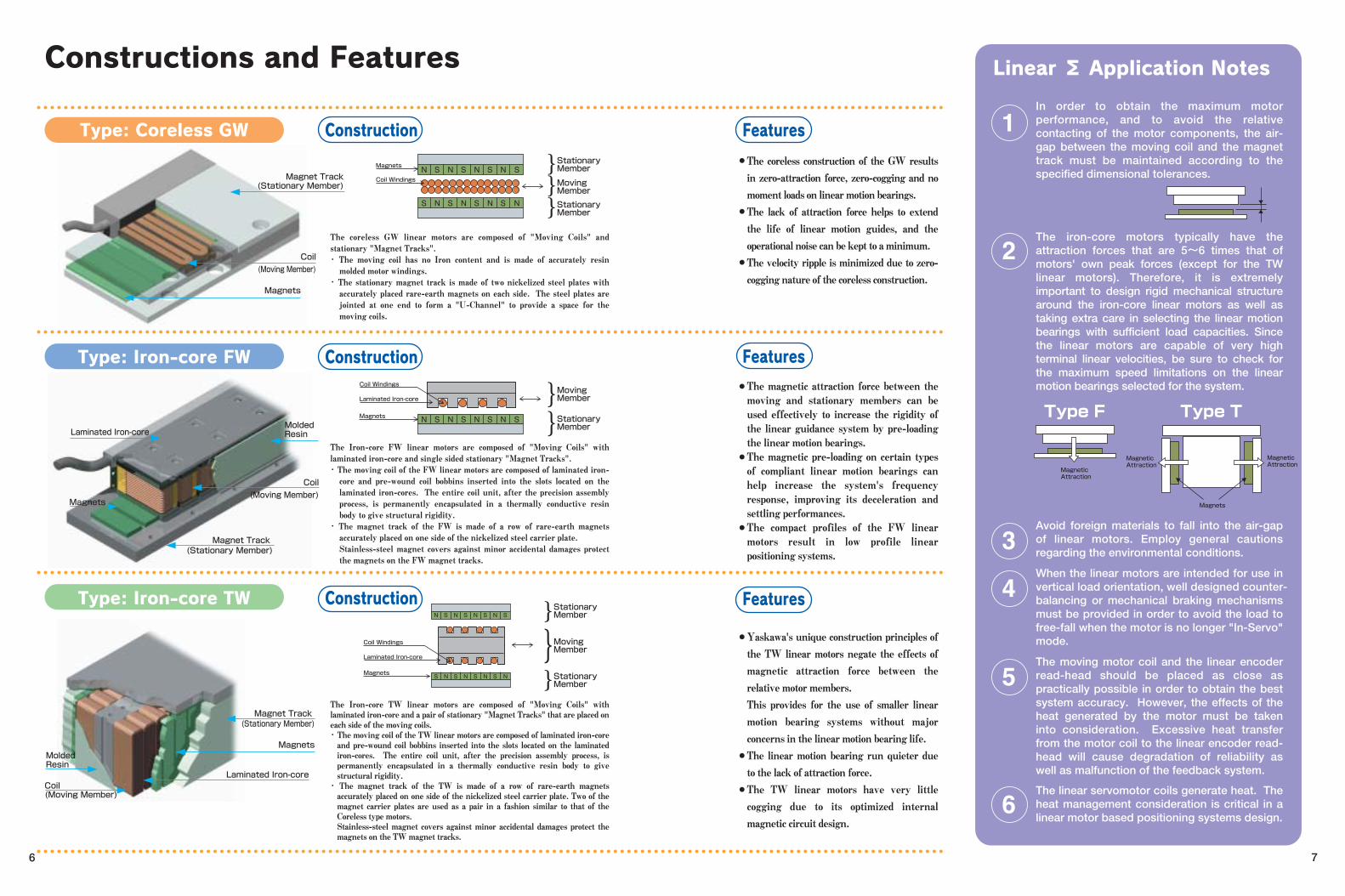
The coreless GW linear motors are composed of "Moving Coils" and stationary "Magnet Tracks". ・ The moving coil has no Iron content and is made of accurately resin molded motor windings.
・ The stationary magnet track is made of two nickelized steel plates with accurately placed rare-earth magnets on each side. The steel plates are jointed at one end to form a "U-Channel" to provide a space for the moving coils.
The Iron-core FW linear motors are composed of "Moving Coils" with laminated iron-core and single sided stationary "Magnet Tracks". ・ The moving coil of the FW linear motors are composed of laminated iron-core and pre-wound coil bobbins inserted into the slots located on the laminated iron-cores. The entire coil unit, after the precision assembly process, is permanently encapsulated in a thermally conductive resin body to give structural rigidity.
・ The magnet track of the FW is made of a row of rare-earth magnets accurately placed on one side of the nickelized steel carrier plate. Stainless-steel magnet covers against minor accidental damages protect the magnets on the FW magnet tracks.
The Iron-core TW linear motors are composed of "Moving Coils" with laminated iron-core and a pair of stationary "Magnet Tracks" that are placed on each side of the moving coils. ・ The moving coil of the TW linear motors are composed of laminated iron-core and pre-wound coil bobbins inserted into the slots located on the laminated iron-cores. The entire coil unit, after the precision assembly process, is permanently encapsulated in a thermally conductive resin body to give structural rigidity. ・ The magnet track of the TW is made of a row of rare-earth magnets accurately placed on one side of the nickelized steel carrier plate. Two of the magnet carrier plates are used as a pair in a fashion similar to that of the Coreless type motors. Stainless-steel magnet covers against minor accidental damages protect the magnets on the TW magnet tracks.
The coreless construction of the GW results in zero-attraction force, zero-cogging and no moment loads on linear motion bearings. The lack of attraction force helps to extend the life of linear motion guides, and the operational noise can be kept to a minimum. The velocity ripple is minimized due to zero-cogging nature of the coreless construction.
In order to obtain the maximum motor performance, and to avoid the relative contacting of the motor components, the air-gap between the moving coil and the magnet track must be maintained according to the specified dimensional tolerances.
●
●
●
The magnetic attraction force between the moving and stationary members can be used effectively to increase the rigidity of the linear guidance system by pre-loading the linear motion bearings. The magnetic pre-loading on certain types of compliant linear motion bearings can help increase the system's frequency response, improving its deceleration and settling performances. The compact profiles of the FW linear motors result in low profile linear positioning systems.
●
●
●
Yaskawa's unique construction principles of the TW linear motors negate the effects of magnetic attraction force between the relative motor members. This provides for the use of smaller linear motion bearing systems without major concerns in the linear motion bearing life. The linear motion bearing run quieter due to the lack of attraction force. The TW linear motors have very little cogging due to its optimized internal magnetic circuit design.
●
●
●
Avoid foreign materials to fall into the air-gap of linear motors. Employ general cautions regarding the environmental conditions.
The iron-core motors typically have the attraction forces that are 5~6 times that of motors' own peak forces (except for the TW linear motors). Therefore, it is extremely important to design rigid mechanical structure around the iron-core linear motors as well as taking extra care in selecting the linear motion bearings with sufficient load capacities. Since the linear motors are capable of very high terminal linear velocities, be sure to check for the maximum speed limitations on the linear motion bearings selected for the system.
When the linear motors are intended for use in vertical load orientation, well designed counter-balancing or mechanical braking mechanisms must be provided in order to avoid the load to free-fall when the motor is no longer "In-Servo" mode.
The moving motor coil and the linear encoder read-head should be placed as close as practically possible in order to obtain the best system accuracy. However, the effects of the heat generated by the motor must be taken into consideration. Excessive heat transfer from the motor coil to the linear encoder read-head will cause degradation of reliability as well as malfunction of the feedback system. The linear servomotor coils generate heat. The heat management consideration is critical in a linear motor based positioning systems design.
N S N S N S N S
Coil WindingsMoving Member
Stationary Member
Laminated Iron-core
Magnets
N S N S N S N S
S N S N S N S N
Coil Windings
Magnets
Moving Member
Stationary Member
Stationary Member
S N S N S N S N
N S N S N S N S
Coil Windings
Laminated Iron-core
Magnets
Moving Member
Stationary Member
Stationary Member
Magnet Track (Stationary Member)
Coil
(Moving Member)
Magnet Track (Stationary Member)
Coil
(Moving Member)
Magnets
Laminated Iron-core
Magnets
Molded Resin
Magnet Track (Stationary Member)
Magnets
Laminated Iron-core
Molded Resin
Coil (Moving Member)
6 7
Constructions and Features
Type: Coreless GW Construction Features
Type: Iron-core FW Construction Features
Type: Iron-core TW Construction Features
Linear Σ Application Notes
Magnetic Attraction
Magnetic Attraction
Magnetic Attraction
Magnets
Type F Type T
40A140
60A140
40A253
40A365
60A253
60A365
20A090
20A120
35A120
35A230
50A200
50A380
1ZA200
1ZA380
20A170
20A320
20A460
35A170
35A320
35A460
40A400
40A600
80A400
80A600
20A170
35A170
20A320
20A460
35A320
35A460
40A400
40A600
80A400
80A600
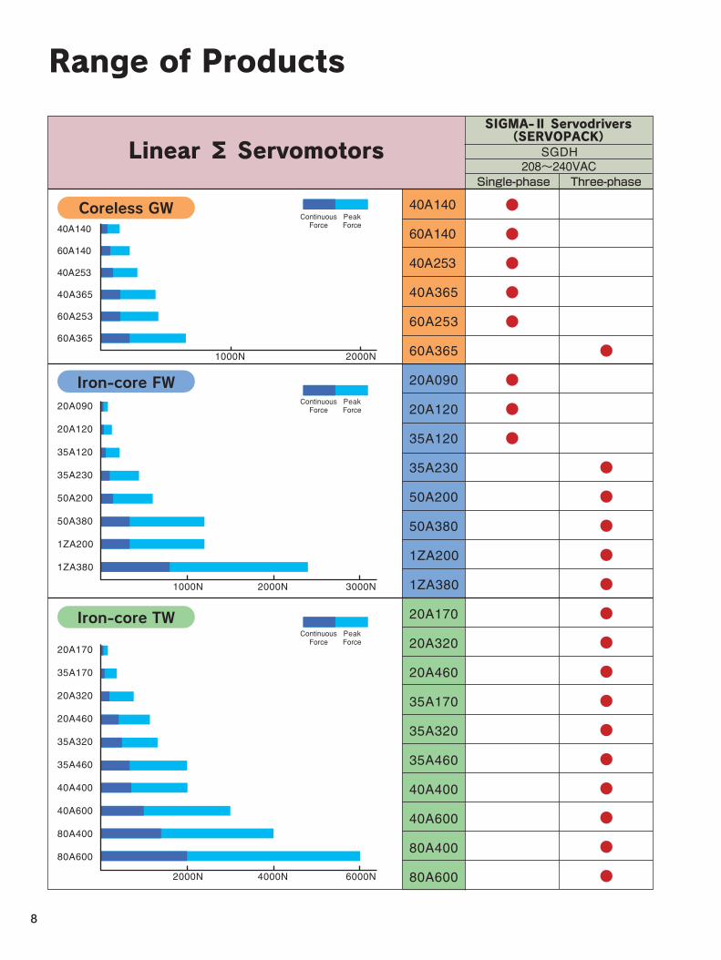
208~240VACSGDH
Single-phase Three-phase
40A140
60A140
40A253
40A365
60A253
60A365
20A090
20A120
35A120
35A230
50A200
50A380
1ZA200
1ZA380
1000N 2000N
2000N1000N 3000N
4000N2000N 6000N
Continuous Force
Peak Force
Continuous Force
Peak Force
Continuous Force
Peak Force
8
Range of Products
Linear Σ Servomotors
Coreless GW
Iron-core FW
Iron-core TW
SIGMA-Ⅱ Servodrivers(SERVOPACK)
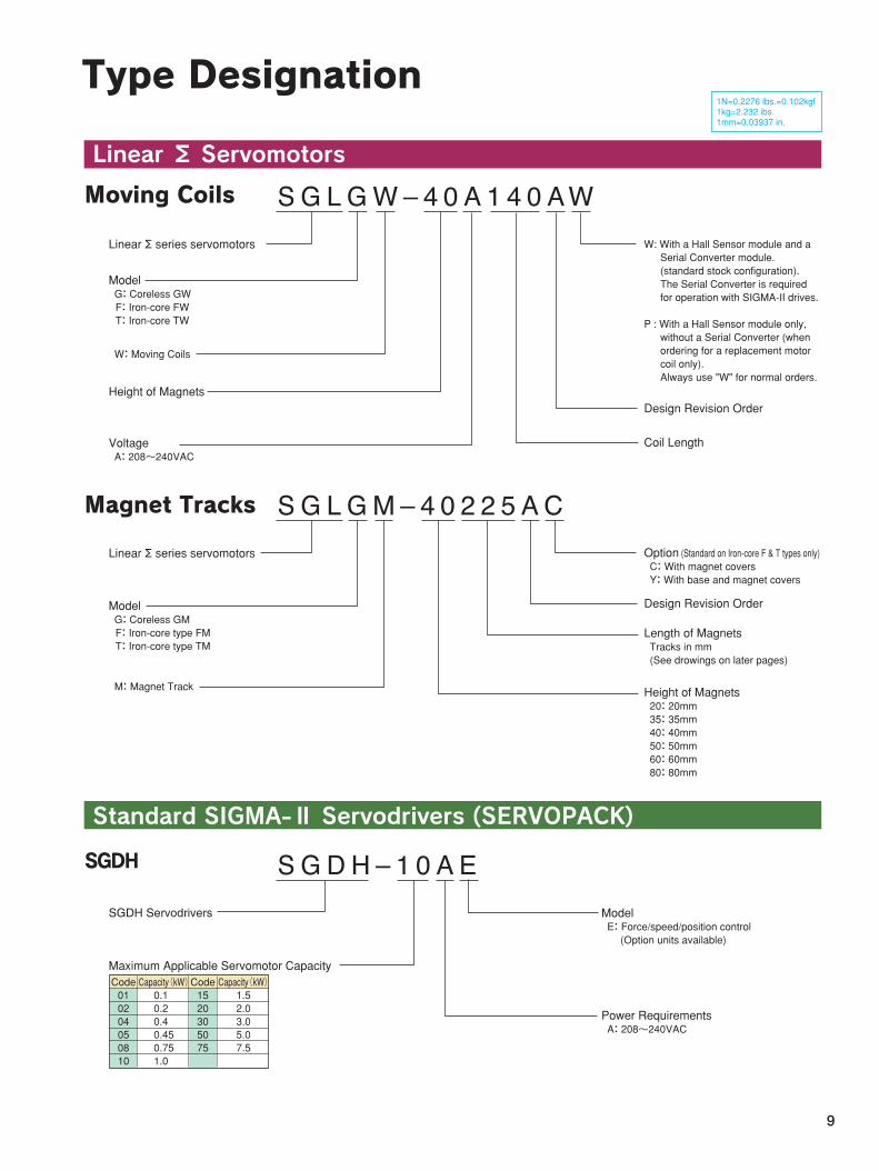
Linear Σ series servomotors
Model G: Coreless GW F: Iron-core FW T: Iron-core TW
W: With a Hall Sensor module and a Serial Converter module. (standard stock configuration). The Serial Converter is required for operation with SIGMA-II drives.
P : With a Hall Sensor module only, without a Serial Converter (when ordering for a replacement motor coil only). Always use "W" for normal orders.
W: Moving Coils
Height of MagnetsDesign Revision Order
Coil LengthVoltage A: 208~240VAC
Linear Σ series servomotors
Model G: Coreless GM F: Iron-core type FM T: Iron-core type TM
Option (Standard on Iron-core F & T types only) C: With magnet covers Y: With base and magnet covers
M: Magnet Track
Design Revision Order
Length of Magnets Tracks in mm (See drowings on later pages)
Height of Magnets 20: 20mm 35: 35mm 40: 40mm 50: 50mm 60: 60mm 80: 80mm
SGDH Servodrivers
Maximum Applicable Servomotor Capacity
Model E: Force/speed/position control (Option units available)
Power Requirements A: 208~240VAC
Code 01 02 04 05 08 10
Capacity(kW) 0.1 0.2 0.4 0.45 0.75 1.0
Capacity(kW) 1.5 2.0 3.0 5.0 7.5
Code 15 20 30 50 75
9
Type Designation
Linear Σ Servomotors
Standard SIGMA-Ⅱ Servodrivers (SERVOPACK)
Moving Coils
Magnet Tracks
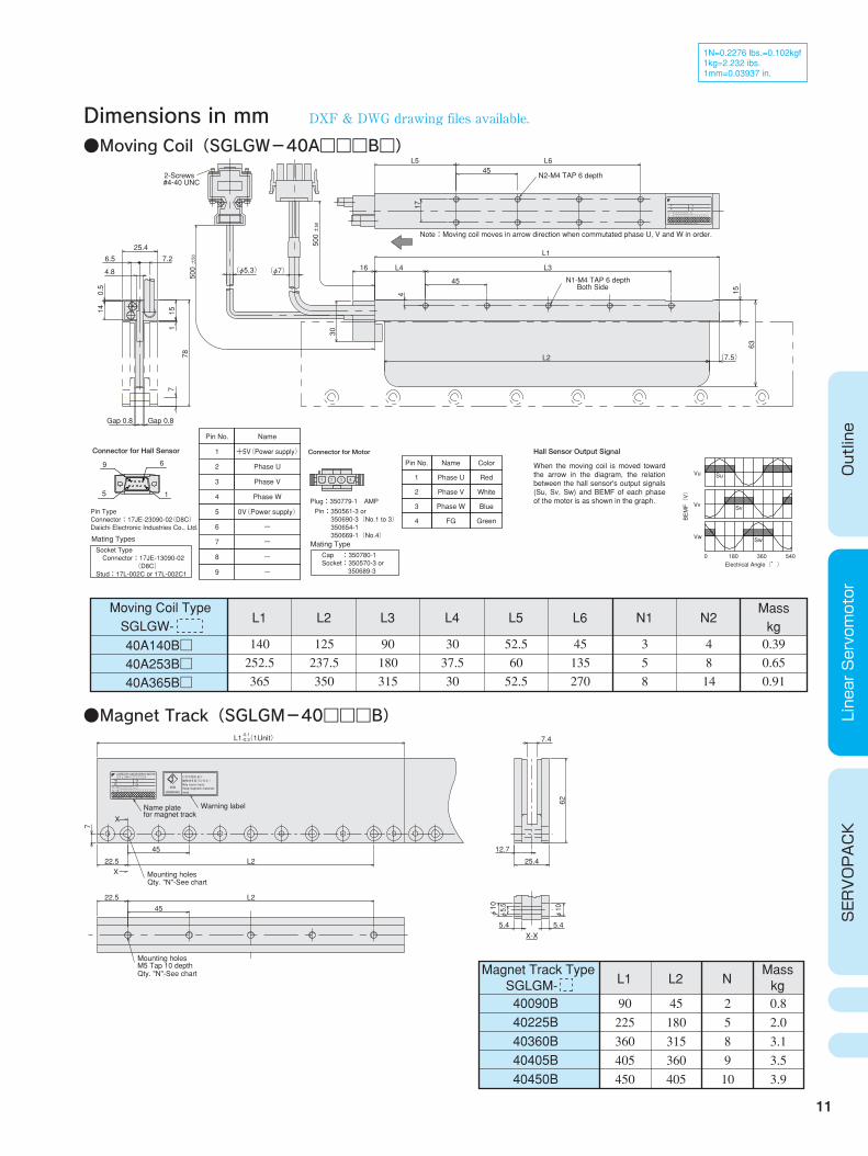
1N=0.2276 lbs.=0.102kgf 1kg=2.232 ibs. 1mm=0.03937 in.
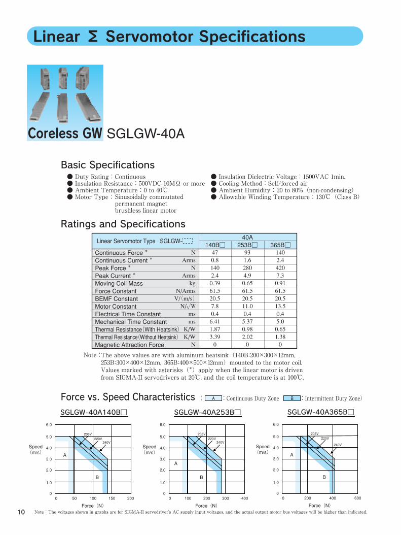
Linear Σ Servomotor Specifications
Coreless GW SGLGW-40A
10
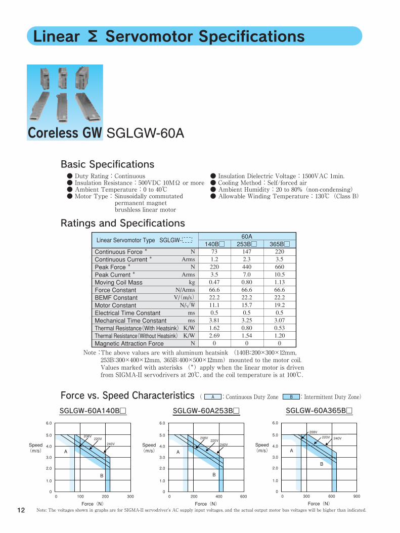
Basic Specifications● Duty Rating:Continuous ● Insulation Resistance:500VDC 10MΩ or more ● Ambient Temperature:0 to 40℃ ● Motor Type:
The above values are with aluminum heatsink(140B:200×300×12mm, 253B:300×400×12mm, 365B:400×500×12mm)mounted to the motor coil. Values marked with asterisks(*)apply when the linear motor is driven from SIGMA-II servodrivers at 20℃, and the coil temperature is at 100℃.
Note:The voltages shown in graphs are for SIGMA-II servodriver's AC supply input voltages, and the actual output motor bus voltages will be higher than indicated.
Note:
Ratings and Specifications
Force vs. Speed Characteristics
● Insulation Dielectric Voltage:1500VAC 1min. ● Cooling Method:Self/forced air ● Ambient Humidity:20 to 80%(non-condensing) ● Allowable Winding Temperature:130℃(Class B)
Linear Servomotor Type SGLGW- 140B□
40A 253B□
365B□
( :Continuous Duty Zone :Intermittent Duty Zone) A B
Sinusoidally commutated permanent magnet brushless linear motor
47 0.8 140 2.4 0.39 61.5 20.5 7.8 0.4 6.41 1.87 3.39 0
N Arms N
Arms kg
N/Arms V/(m/s) N/√W ms ms K/W K/W N
93 1.6 280 4.9 0.65 61.5 20.5 11.0 0.4 5.37 0.98 2.02 0
140 2.4 420 7.3 0.91 61.5 20.5 13.5 0.4 5.0 0.65 1.38 0
SGLGW-40A140B□
6.0
5.0
4.0
3.0
2.0
1.0
00 50 100 150 200
Speed (m/s)
Force(N)
A
B
208V220V
240V
208V220V
240V
SGLGW-40A253B□
6.0
5.0
4.0
3.0
2.0
1.0
00 100 200 300 400
Speed (m/s)
Force(N)
A
B
SGLGW-40A365B□
6.0
5.0
4.0
3.0
2.0
1.0
00 200 400 600
Speed (m/s)
Force(N)
A
B
Continuous Force * Continuous Current * Peak Force * Peak Current * Moving Coil Mass Force Constant BEMF Constant Motor Constant Electrical Time Constant Mechanical Time Constant Thermal Resistance(With Heatsink) Thermal Resistance(Without Heatsink) Magnetic Attraction Force
208V220V
240V
11
Outline
Linear Servomotor
SERVOPACK
1N=0.2276 lbs.=0.102kgf 1kg=2.232 ibs. 1mm=0.03937 in.
DXF & DWG drawing files available.
Note:Moving coil moves in arrow direction when commutated phase U, V and W in order.
Connector for Hall Sensor
9 6
15
Pin Type Connector:17JE-23090-02(D8C) Daiichi Electronic Industries Co., Ltd.
Mating TypesSocket Type Connector:17JE-13090-02 (D8C) Stud:17L-002C or 17L-002C1
Pin No.
1
2
3
4
5
6
7
8
9
Name
+5V(Power supply)
Phase U
Phase V
Phase W
0V(Power supply)
-
-
-
-
Connector for Motor
Plug:350779-1 AMP
Pin:350561-3 or 350690-3(No.1 to 3) 350654-1 350669-1(No.4) Mating TypeCap :350780-1 Socket:350570-3 or 350689-3
Pin No.
1
2
3
4
Name
Phase U
Phase V
Phase W
FG
Color
Red
White
Blue
Green
Hall Sensor Output Signal
When the moving coil is moved toward the arrow in the diagram, the relation between the hall sensor's output signals (Su, Sv, Sw) and BEMF of each phase of the motor is as shown in the graph.
BEMF(V)
Electrical Angle(°)
Vu
Vv
Vw
Su
Sv
Sw
0 180 360 540
Moving Coil Type SGLGW- 40A140B□ 40A253B□ 40A365B□
L1
140 252.5 365
L2
125 237.5 350
L3
90 180 315
L4
30 37.5 30
L5
52.5 60 52.5
L6
45 135 270
N1
3 5 8
N2Mass kg
4 8 14
0.39 0.65 0.91
●Moving Coil(SGLGW-40A□□□B□)
Dimensions in mm
●Magnet Track(SGLGM-40□□□B)
Magnet Track Type SGLGM- L1
40090B 40225B 40360B 40405B 40450B
90 225 360 405 450
L2
45 180 315 360 405
N
2 5 8 9 10
Mass kg0.8 2.0 3.1 3.5 3.9
L2
L2
L1 (1Unit)
Mounting holes
for magnet track
Mounting holes
M5 Tap 10 depth
Warning labelName plate
φ10
φ10
5.4 5.4
12.7
25.4
62
7.4
22.5
45
22.5
45
Qty. "N"-See chart
φ5.5
7
X
X
X-X
Qty. "N"-See chart
--
- -
O/N□□□□□□-□ S/N□□□□□□□□□□□□□□□
SGLGM-□□□□□A
N
CORELESS LINEAR SERVO MOTOR
Ins.AW
YASKAWA ELECTRIC CORPORATION JAPAN
Keep magnetic materials
磁性体を近づけるな! May cause injury.
away.
危険
WARNING
けがの恐れあり
-0.1 -0.3
25.4
7.26.5
7
15
63
30
(φ7) (φ5.3)
4
500±50
500±50
(7.5) L2
17
L5 L6
#4-40 UNC2-Screws
115
78
Gap 0.8 Gap 0.8
4.8
140.5
45N2-M4 TAP 6 depth
Both SideN1-M4 TAP 6 depth
L1
L316 L4
45
S/N□□□□□□□□□□□□□□□ O/N□□□□□□-□
N Ins.AW
YASKAWA ELECTRIC CORPORATION JAPAN
12
Linear Σ Servomotor Specifications
Coreless GW SGLGW-60A
Basic Specifications
The above values are with aluminum heatsink (140B:200×300×12mm, 253B:300×400×12mm, 365B:400×500×12mm)mounted to the motor coil. Values marked with asterisks (*)apply when the linear motor is driven from SIGMA-II servodrivers at 20℃, and the coil temperature is at 100℃.
( :Continuous Duty Zone :Intermittent Duty Zone) A B
Note: The voltages shown in graphs are for SIGMA-II servodriver's AC supply input voltages, and the actual output motor bus voltages will be higher than indicated.
Force vs. Speed Characteristics
Ratings and Specifications
Note:
Linear Servomotor Type SGLGW- 140B□
60A 253B□
365B□
● Duty Rating:Continuous ● Insulation Resistance:500VDC 10MΩ or more ● Ambient Temperature:0 to 40℃ ● Motor Type:
● Insulation Dielectric Voltage:1500VAC 1min. ● Cooling Method:Self/forced air ● Ambient Humidity:20 to 80%(non-condensing) ● Allowable Winding Temperature:130℃(Class B) Sinusoidally commutated
permanent magnet brushless linear motor
73 1.2 220 3.5 0.47 66.6 22.2 11.1 0.5 3.81 1.62 2.69 0
N Arms N
Arms kg
N/Arms V/(m/s) N/√W ms ms K/W K/W N
147 2.3 440 7.0 0.80 66.6 22.2 15.7 0.5 3.25 0.80 1.54 0
220 3.5 660 10.5 1.13 66.6 22.2 19.2 0.5 3.07 0.53 1.20 0
Continuous Force * Continuous Current * Peak Force * Peak Current * Moving Coil Mass Force Constant BEMF Constant Motor Constant Electrical Time Constant Mechanical Time Constant Thermal Resistance(With Heatsink) Thermal Resistance(Without Heatsink) Magnetic Attraction Force
SGLGW-60A140B□
6.0
5.0
4.0
3.0
2.0
1.0
00 100 200 300
Speed (m/s)
Force(N)
A
B
SGLGW-60A253B□
6.0
5.0
4.0
3.0
2.0
1.0
00 200 400 600
Speed (m/s)
Force(N)
A
B
SGLGW-60A365B□
6.0
5.0
4.0
3.0
2.0
1.0
00 300 600 900
Speed (m/s)
Force(N)
A
B
208V
220V 240V208V
220V240V
208V220V
240V
L2
L2
L1 (1Unit)
Mounting holes
for magnet track
Mounting holes
M5 Tap 10 depth
Warning labelName plate
φ10
φ10
5.4 5.4
12.7
25.4
82
7.4
22.5
45
22.5
45
Qty. "N"-See chart
φ5.5
7
X
X
X-X
Qty. "N"-See chart
--
- -
O/N□□□□□□-□ S/N□□□□□□□□□□□□□□□
SGLGM-□□□□□A
N
CORELESS LINEAR SERVO MOTOR
Ins.AW
YASKAWA ELECTRIC CORPORATION JAPAN
Keep magnetic materials
磁性体を近づけるな! May cause injury.
away.危険
WARNING
けがの恐れあり
-0.1 -0.3
13
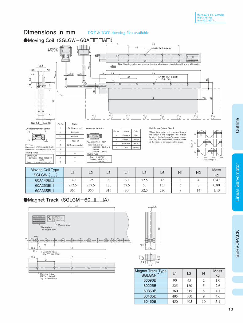
1N=0.2276 lbs.=0.102kgf 1kg=2.232 ibs. 1mm=0.03937 in.
Dimensions in mm
Outline
Linear Servomotor
SERVOPACK
Connector for Hall Sensor
9 6
15
Pin Type Connector:17JE-23090-02(D8C) Daiichi Electronic Industries Co., Ltd.
Mating TypesSocket Type Connector:17JE-13090-02 (D8C) Stud:17L-002C or 17L-002C1
Pin No.
1
2
3
4
5
6
7
8
9
Name
+5V(Power supply)
Phase U
Phase V
Phase W
0V(Power supply)
-
-
-
-
Connector for Motor
Plug:350779-1 AMP
Pin:350561-3 or 350690-3(No.1 to 3) 350654-1 350669-1(No.4) Mating TypeCap :350780-1 Socket:350570-3 or 350689-3
Pin No.
1
2
3
4
Name
Phase V
Phase U
Phase W
FG
Color
Red
White
Blue
Green
Hall Sensor Output Signal
When the moving coil is moved toward the arrow in the diagram, the relation between the hall sensor's output signals (Su, Sv, Sw) and BEMF of each phase of the motor is as shown in the graph.
BEMF(V)
Electrical Angle(°)
Vu
Vv
Vw
Su
Sv
Sw
0 180 360 540
Moving Coil Type SGLGW- 60A140B□ 60A253B□ 60A365B□
L1
140 252.5 365
L2
125 237.5 350
L3
90 180 315
L4
30 37.5 30
L5
52.5 60 52.5
L6
45 135 270
N1
3 5 8
N2Mass kg
4 8 14
0.47 0.80 1.13
●Magnet Track(SGLGM-60□□□A)
●Moving Coil(SGLGW-60A□□□A□)
Magnet Track Type SGLGM- L1
60090B 60225B 60360B 60405B 60450B
90 225 360 405 450
L2
45 180 315 360 405
N
2 5 8 9 10
Mass kg1.0 2.6 4.1 4.6 5.1
Note:Moving coil moves in arrow direction when commutated phase U, V and W in order.
7
15
25.4
83
7.26.5
17
L645
L5
30
(φ7)
500±50
16 L4
45
L1
L3
(7.5) L2
(φ5.3)
500±50
4.8
115
0.5
14
Gap 0.8 Gap 0.8
98
4
#4-40 UNC2-Screws N2-M4 TAP 6 depth
Both SideN1-M4 TAP 6 depth
S/N□□□□□□□□□□□□□□□ O/N□□□□□□-□ N Ins.
AW
YASKAWA ELECTRIC CORPORATION JAPAN
DXF & DWG drawing files available.
14
Basic Specifications
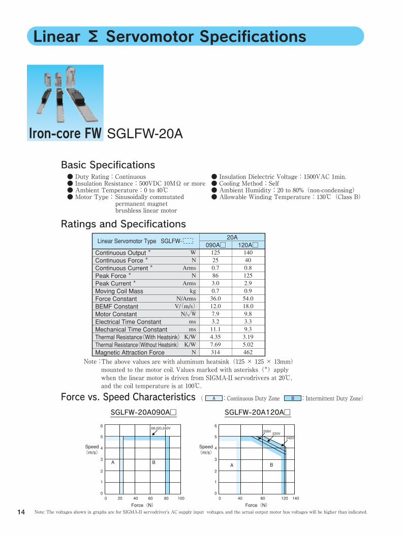
Iron-core FW SGLFW-20A
Linear Σ Servomotor Specifications
The above values are with aluminum heatsink(125 × 125 × 13mm) mounted to the motor coil. Values marked with asterisks(*)apply when the linear motor is driven from SIGMA-II servodrivers at 20℃, and the coil temperature is at 100℃.
Ratings and Specifications
Note:
Linear Servomotor Type SGLFW- 090A□
120A□
20A
Note: The voltages shown in graphs are for SIGMA-II servodriver's AC supply input voltages, and the actual output motor bus voltages will be higher than indicated.
Force vs. Speed Characteristics ( :Continuous Duty Zone :Intermittent Duty Zone) A B
● Duty Rating:Continuous ● Insulation Resistance:500VDC 10MΩ or more ● Ambient Temperature:0 to 40℃ ● Motor Type:
● Insulation Dielectric Voltage:1500VAC 1min. ● Cooling Method:Self ● Ambient Humidity:20 to 80%(non-condensing) ● Allowable Winding Temperature:130℃(Class B) Sinusoidally commutated
permanent magnet brushless linear motor
125 25 0.7 86 3.0 0.7 36.0 12.0 7.9 3.2 11.1 4.35 7.69 314
W N
Arms N
Arms kg
N/Arms V/(m/s) N/√W ms ms K/W K/W N
140 40 0.8 125 2.9 0.9 54.0 18.0 9.8 3.3 9.3 3.19 5.02 462
SGLFW-20A090A□
6
5
4
3
2
1
00 20 40 60 80 100
Speed (m/s)
Force(N)
A B
SGLFW-20A120A□
6
5
4
3
2
1
00 40 80 120 140
Speed (m/s)
Force(N)
A B
208V220V
240V
Continuous Output * Continuous Force * Continuous Current * Peak Force * Peak Current * Moving Coil Mass Force Constant BEMF Constant Motor Constant Electrical Time Constant Mechanical Time Constant Thermal Resistance(With Heatsink) Thermal Resistance(Without Heatsink) Magnetic Attraction Force
208,220,240V
15
Dimensions in mm
Outline
Linear Servomotor
SERVOPACK
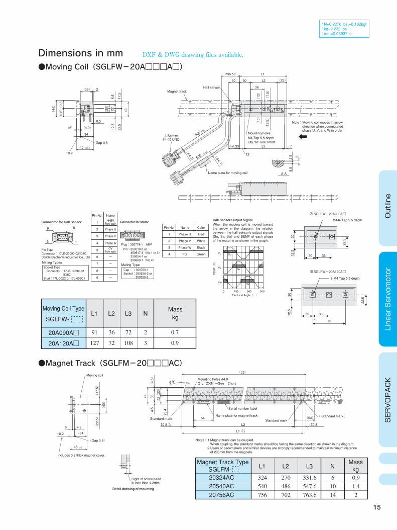
●Moving Coil(SGLFW-20A□□□A□)
1N=0.2276 lbs.=0.102kgf 1kg=2.232 ibs. 1mm=0.03937 in.
Socket Type Connector:17JE-13090-02 (D8C) Stud:17L-002C or 17L-002C1
Pin No.
1
2
3
4
5
6
7
8
9
Name
Phase U
Phase V
Phase W
-
-
-
-
Connector for Motor
Plug:350779-1 AMP
Pin:350218-3 or 350547-3(No.1 to 3) 350654-1 or 350669-1(No.4)
Mating TypeCap :350780-1 Socket:350536-3 or 350550-3
BEMF(V)
Electrical Angle(°)
Vu
Vv
Vw
Su
Sv
Sw
0 180 360 540
Moving Coil Type
SGLFW-
20A090A□
20A120A□
L1
91
127
L2
36
72
L3
72
108
2
3
N
Connector for Hall Sensor
Detail drawing of mounting
9 6
15
Pin Type Connector:17JE-23090-02(D8C) Daiichi Electronic Industries Co., Ltd.
Mating Types
Pin No.
1
2
3
4
Name
Phase U
Phase V
Phase W
FG
Color
Red
White
Black
Green
Hall Sensor Output SignalWhen the moving coil is moved toward the arrow in the diagram, the relation between the hall sensor's output signals (Su, Sv, Sw) and BEMF of each phase of the motor is as shown in the graph.
2-M4 Tap 5.5 depth
3-M4 Tap 5.5 depth
2020
12.5
12.5
22.5
22.5
30
30
36
36
72
●Magnet Track(SGLFM-20□□□AC)
Mass kg
0.7
0.9
○ A
○ B
SGLFWー20A090A□
SGLFWー20A120A□
Magnet Track Type SGLFM- L1
20324AC 20540AC 20756AC
324 540 756
L2
270 486 702
L3
331.6 547.6 763.6
N
6 10 14
Mass kg0.9 1.4 2
+5V (Power supply)
0V (Power supply)
Notes:1 Magnet track can be coupled. When coupling, the standard marks should be facing the same direction as shown in the diagram. 2 Users of pacemakers and similar devices are strongly recommended to maintain minimum distance of 200mm from the magnets.
Note:Moving coil moves in arrow direction when commutated phase U, V, and W in order.
2-Screws#4-40 UNC
Magnet trackHall sensor
min.50
12
Mounting holesM4 Tap 5.5 depthQty."N"-See Chart
Name plate for moving coil
Gap 0.8
±50
500
10.2
A-A
±50
500
A A
7
2
min.30
82.5
5.5
L3
(12.5)
(φ6.1)
(φ4.2)
36
(25)
L1
L23030
5.5
(12)
(7.5)
20
(10)
22.5
40
17.5
12.5
(4.2)
±0.145
34
(44)
(22) (22)
(32)
0.5
(6)
Standard markStandard mark( Standard mark )
Mounting holes φ4.8
Name plate for magnet track
Serial number label
(Gap 0.8)
Moving coil
Includes 0.2 thick magnet cover.
is less than 4.2mm.Hight of screw head
Qty.″2×N″-See Chart
SNSNSN
S/N
O/N
TYPE: MADE IN JAPAN DATE
S/N
O/N
MADE IN
YASKAWATYPE:YASKAWA
-0.3-0.1L1
6 4.2
±0.145
(L3)
-0.2030.8
54 (54)
(30.8) L2
4.5
25.4
9.9゚
(4.5)
(22)
22
3544
(22.5)
(40)
(17.5)
(34) 10.2
(20)
22
DXF & DWG drawing files available.
16
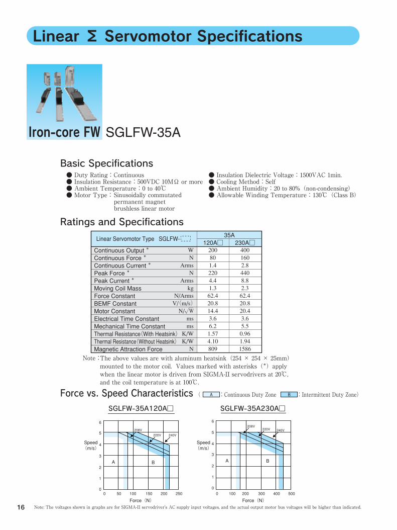
Basic Specifications
Iron-core FW SGLFW-35A
Linear Σ Servomotor Specifications
The above values are with aluminum heatsink(254 × 254 × 25mm) mounted to the motor coil. Values marked with asterisks(*)apply when the linear motor is driven from SIGMA-II servodrivers at 20℃, and the coil temperature is at 100℃.
Note: The voltages shown in graphs are for SIGMA-II servodriver's AC supply input voltages, and the actual output motor bus voltages will be higher than indicated.
Force vs. Speed Characteristics ( :Continuous Duty Zone :Intermittent Duty Zone) A B
Ratings and Specifications
Note:
Linear Servomotor Type SGLFW- 120A□
230A□
35A
● Duty Rating:Continuous ● Insulation Resistance:500VDC 10MΩ or more ● Ambient Temperature:0 to 40℃ ● Motor Type:
● Insulation Dielectric Voltage:1500VAC 1min. ● Cooling Method:Self ● Ambient Humidity:20 to 80%(non-condensing) ● Allowable Winding Temperature:130℃(Class B) Sinusoidally commutated
permanent magnet brushless linear motor
200 80 1.4 220 4.4 1.3 62.4 20.8 14.4 3.6 6.2 1.57 4.10 809
W N
Arms N
Arms kg
N/Arms V/(m/s) N/√W ms ms K/W K/W N
400 160 2.8 440 8.8 2.3 62.4 20.8 20.4 3.6 5.5 0.96 1.94 1586
Continuous Output * Continuous Force * Continuous Current * Peak Force * Peak Current * Moving Coil Mass Force Constant BEMF Constant Motor Constant Electrical Time Constant Mechanical Time Constant Thermal Resistance(With Heatsink) Thermal Resistance(Without Heatsink) Magnetic Attraction Force
SGLFW-35A120A□
6
5
4
3
2
1
00 50 100 150 200 250
Speed (m/s)
Force(N)
A B
SGLFW-35A230A□
6
5
4
3
2
1
00 100 200 300 400 500
Speed (m/s)
Force(N)
A B
208V
220V 240V
208V220V 240V
17
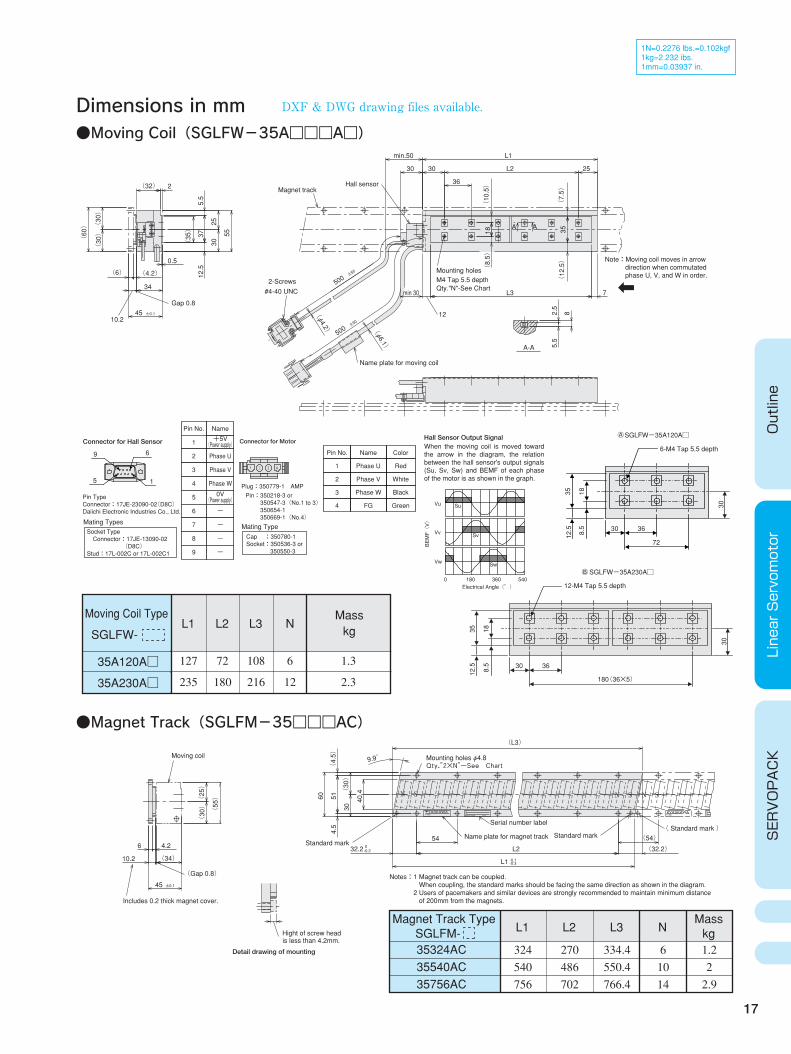
Dimensions in mm
Outline
Linear Servomotor
SERVOPACK
1N=0.2276 lbs.=0.102kgf 1kg=2.232 ibs. 1mm=0.03937 in.
●Moving Coil(SGLFW-35A□□□A□)
Socket Type Connector:17JE-13090-02 (D8C) Stud:17L-002C or 17L-002C1
Vu
Vv
Vw
Su
Sv
Sw
0 180 360 540
Connector for Hall Sensor
9 6
15
Pin Type Connector:17JE-23090-02(D8C) Daiichi Electronic Industries Co., Ltd.
Mating Types
●Magnet Track(SGLFM-35□□□AC)
6-M4 Tap 5.5 depth
35 188.5
12.5 30 36
72
12-M4 Tap 5.5 depth
35 18
3030
8.5
12.5 30 36
180(36×5)
SGLFWー35A120A□
SGLFWー35A230A□
Connector for Motor
Plug:350779-1 AMP
Pin:350218-3 or 350547-3(No.1 to 3) 350654-1 350669-1(No.4)
Mating TypeCap :350780-1 Socket:350536-3 or 350550-3
BEMF(V)
Electrical Angle(°)
Pin No.
1
2
3
4
Name
Phase U
Phase V
Phase W
FG
Color
Red
White
Black
Green
Hall Sensor Output SignalWhen the moving coil is moved toward the arrow in the diagram, the relation between the hall sensor's output signals (Su, Sv, Sw) and BEMF of each phase of the motor is as shown in the graph.
○ A
○ B
Pin No.
1
2
3
4
5
6
7
8
9
Name
Phase U
Phase V
Phase W
-
-
-
-
+5V (Power supply)
0V (Power supply)
Moving Coil Type
SGLFW-
35A120A□
35A230A□
L1
127
235
L2
72
180
L3
108
216
6
12
NMass kg
1.3
2.3
Magnet Track Type SGLFM- L1
35324AC 35540AC 35756AC
324 540 756
L2
270 486 702
L3
334.4 550.4 766.4
N
6 10 14
Mass kg1.2 2 2.9
Notes:1 Magnet track can be coupled. When coupling, the standard marks should be facing the same direction as shown in the diagram. 2 Users of pacemakers and similar devices are strongly recommended to maintain minimum distance of 200mm from the magnets.
Detail drawing of mounting
DXF & DWG drawing files available.
2-Screws
Magnet track
Mounting holes±50
500 M4 Tap 5.5 depth
Qty."N"-See Chart
Name plate for moving coil
#4-40 UNC
Hall sensor
A-A
12±50
500
A A
7
min.50 L1
30
(φ6.1)
(φ4.2)
375.5
(10.5)
(35)
2
5.5
8(12.5)
(7.5)
35
L3min 30
L230
±0.145
34
(4.2)
(32)
0.5
(6)
2.5
25
36
55
3025
12.5
(30) (30)
(8.5)
18
(60)
Gap 0.8
10.2
Note:Moving coil moves in arrow direction when commutated phase U, V, and W in order.
Standard markStandard markName plate for magnet track
Serial number label
(Gap 0.8)
is less than 4.2mm.Hight of screw head
( Standard mark )
Mounting holes φ4.8Qty.″2×N″-See Chart
SNS SNN
-0.3-0.1L1
6 4.2
10.2 (34)
±0.145
-0.2032.2
54 (54)
(32.2) L2
4.5
51(4.5)
(L3)
9.9゚
(30)
30
60(25)
(30)
(55)
Moving coil
Includes 0.2 thick magnet cover.
40.4
S/N
O/N
TYPE: MADE IN JAPAN DATE
YASKAWAS/N
O/N
TYPE: MADE
YASKAWA
18
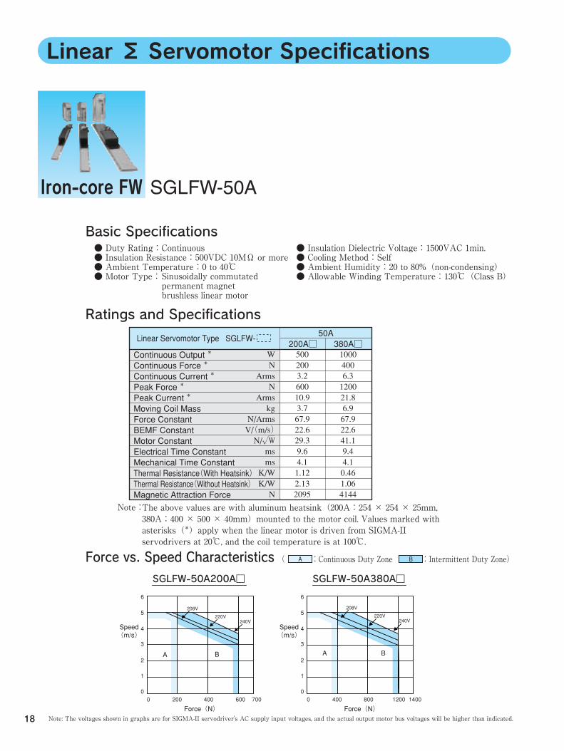
Linear Σ Servomotor Specifications
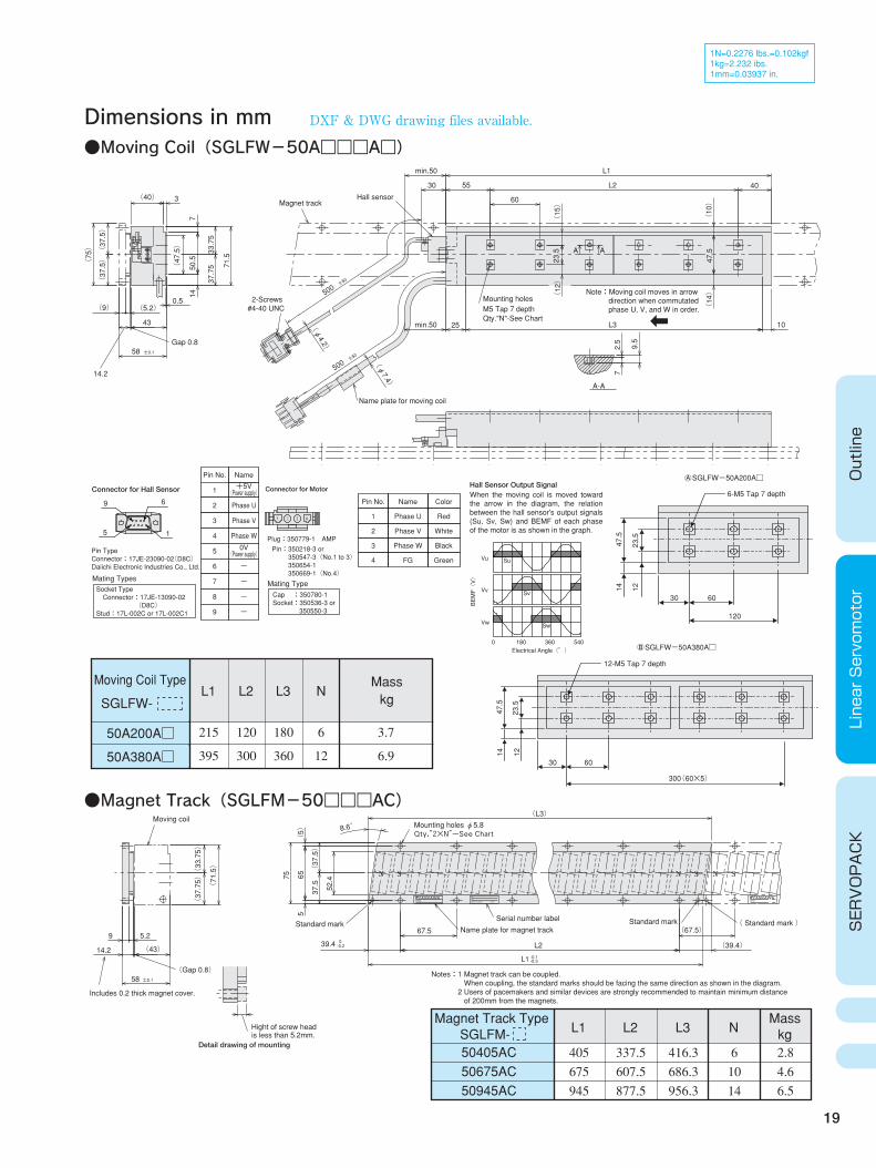
Iron-core FW SGLFW-50A
Basic Specifications
The above values are with aluminum heatsink(200A:254 × 254 × 25mm, 380A:400 × 500 × 40mm)mounted to the motor coil. Values marked with asterisks(*)apply when the linear motor is driven from SIGMA-II servodrivers at 20℃, and the coil temperature is at 100℃.
Ratings and Specifications
Note:
Linear Servomotor Type SGLFW- 200A□
380A□
50A
( :Continuous Duty Zone :Intermittent Duty Zone) A B
Note: The voltages shown in graphs are for SIGMA-II servodriver's AC supply input voltages, and the actual output motor bus voltages will be higher than indicated.
Force vs. Speed Characteristics
● Duty Rating:Continuous ● Insulation Resistance:500VDC 10MΩ or more ● Ambient Temperature:0 to 40℃ ● Motor Type:
● Insulation Dielectric Voltage:1500VAC 1min. ● Cooling Method:Self ● Ambient Humidity:20 to 80%(non-condensing) ● Allowable Winding Temperature:130℃(Class B) Sinusoidally commutated
permanent magnet brushless linear motor
500 200 3.2 600 10.9 3.7 67.9 22.6 29.3 9.6 4.1 1.12 2.13 2095
W N
Arms N
Arms kg
N/Arms V/(m/s) N/√W ms ms K/W K/W N
1000 400 6.3 1200 21.8 6.9 67.9 22.6 41.1 9.4 4.1 0.46 1.06 4144
Continuous Output * Continuous Force * Continuous Current * Peak Force * Peak Current * Moving Coil Mass Force Constant BEMF Constant Motor Constant Electrical Time Constant Mechanical Time Constant Thermal Resistance(With Heatsink) Thermal Resistance(Without Heatsink) Magnetic Attraction Force
SGLFW-50A200A□
6
5
4
3
2
1
00 200 400 600 700
Speed (m/s)
Force(N)
A B
SGLFW-50A380A□
6
5
4
3
2
1
00 400 800 1200 1400
Speed (m/s)
Force(N)
A B
208V
220V240V
208V
220V240V
19
Dimensions in mm
Outline
Linear Servomotor
SERVOPACK
●Moving Coil(SGLFW-50A□□□A□)
●Magnet Track(SGLFM-50□□□AC)
6-M5 Tap 7 depth
47.5
23.5
1214
30 60
120
12-M5 Tap 7 depth
47.5
23.5
1214
30 60
300(60×5)
SGLFWー50A380A□
SGLFWー50A200A□
Socket Type Connector:17JE-13090-02 (D8C) Stud:17L-002C or 17L-002C1
Vu
Vv
Vw
Su
Sv
Sw
0 180 360 540
Connector for Hall Sensor
9 6
15
Pin Type Connector:17JE-23090-02(D8C) Daiichi Electronic Industries Co., Ltd.
Mating Types
Connector for Motor
Plug:350779-1 AMP
Pin:350218-3 or 350547-3(No.1 to 3) 350654-1 350669-1(No.4)
Mating TypeCap :350780-1 Socket:350536-3 or 350550-3
BEMF(V)
Electrical Angle(°)
Pin No.
1
2
3
4
Name
Phase U
Phase V
Phase W
FG
Color
Red
White
Black
Green
Hall Sensor Output SignalWhen the moving coil is moved toward the arrow in the diagram, the relation between the hall sensor's output signals (Su, Sv, Sw) and BEMF of each phase of the motor is as shown in the graph.
○ A
○ B
1N=0.2276 lbs.=0.102kgf 1kg=2.232 ibs. 1mm=0.03937 in.
Pin No.
1
2
3
4
5
6
7
8
9
Name
Phase U
Phase V
Phase W
-
-
-
-
+5V (Power supply)
0V (Power supply)
Moving Coil Type
SGLFW-
50A200A□
50A380A□
L1
215
395
L2
120
300
L3
180
360
6
12
NMass kg
3.7
6.9
Magnet Track Type SGLFM- L1
50405AC 50675AC 50945AC
405 675 945
L2
337.5 607.5 877.5
L3
416.3 686.3 956.3
N
6 10 14
Mass kg2.8 4.6 6.5
Notes:1 Magnet track can be coupled. When coupling, the standard marks should be facing the same direction as shown in the diagram. 2 Users of pacemakers and similar devices are strongly recommended to maintain minimum distance of 200mm from the magnets.
DXF & DWG drawing files available.
Mounting holes2-Screws
14.2
Hall sensor
Qty."N"-See ChartM5 Tap 7 depth
Name plate for moving coil
#4-40 UNC
A-A
±50
500
±50
500
A A
10
30
min.50
min.50
(φ7.4)
50.5
33.75
37.75
(φ4.2)
(47.5)
(14)
(15)
(10)
2.5
9.5
7
L3
L2
L1
7
71.5
143
(37.5)
(75)
(37.5)
(40)
43
±0.158
(5.2)
25
55 40
60
0.5(9)
(12)
Gap 0.8
Note:Moving coil moves in arrow direction when commutated phase U, V, and W in order.
Standard markName plate for magnet track
Serial number label
Mounting holes φ5.8Qty.″2×N″-See Chart
Includes 0.2 thick magnet cover.
Detail drawing of mounting
( Standard mark ) Standard mark
(Gap 0.8)
is less than 5.2mm.Hight of screw head
SSS NNN
-0.3-0.1L1
(L3)
9 5.2
(43) 14.2
±0.158
-0.2039.4
67.5 (67.5)
(39.4) L2
8.6゚
75
5
37.5(37.5) (5)
65
52.4
(71.5)
(33.75)
(37.75)
Moving coil
S/N
O/N
TYPE: MADE IN JAPAN DATE
YASKAWATYPE:YASKAWA
Magnet track
23.5
47.5
20
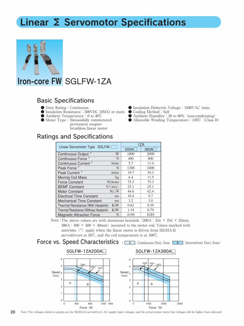
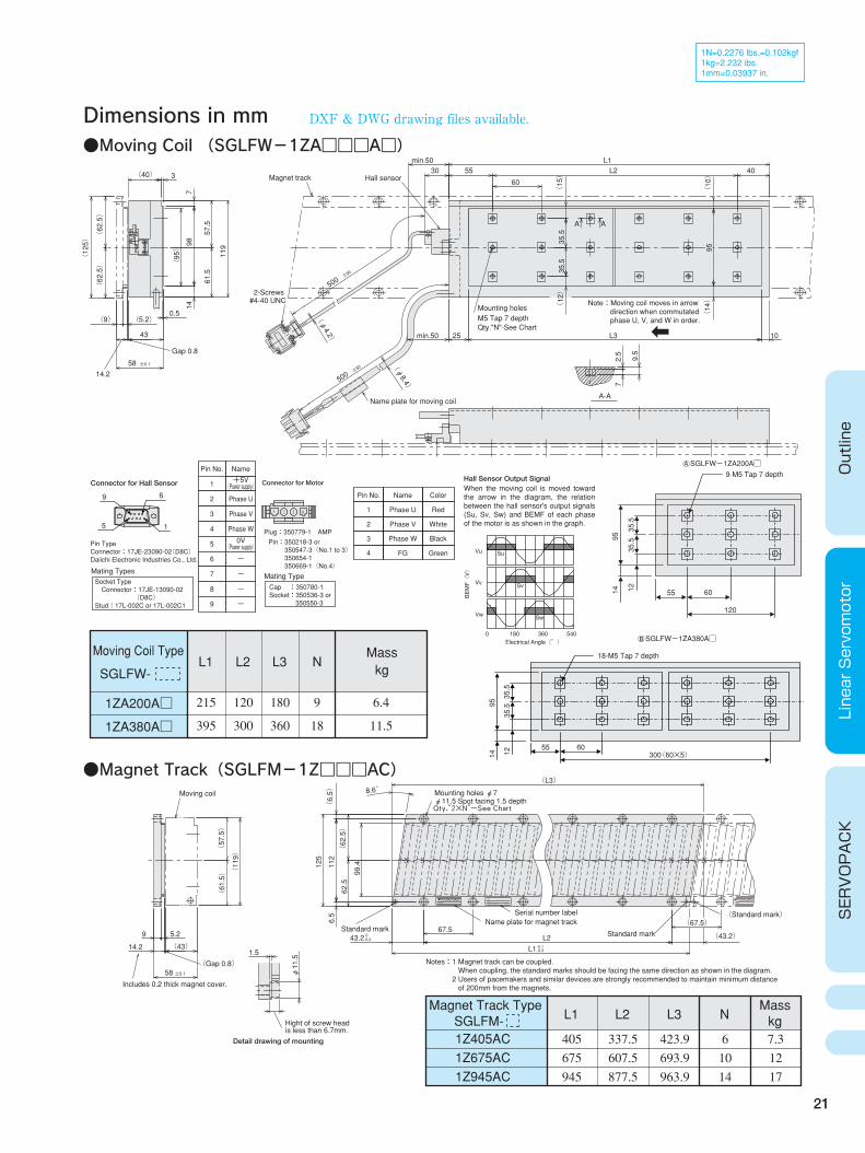
SGLFW-1ZA
Linear Σ Servomotor Specifications
Iron-core FW
Basic Specifications
The above values are with aluminum heatsink(200A:254 × 254 × 25mm, 380A:400 × 500 × 40mm)mounted to the motor coil. Values marked with asterisks(*)apply when the linear motor is driven from SIGMA-II servodrivers at 20℃, and the coil temperature is at 100℃.
Ratings and Specifications
Note:
Linear Servomotor Type SGLFW- 200A□
380A□
1ZA
( :Continuous Duty Zone :Intermittent Duty Zone) A B
Note: The voltages shown in graphs are for SIGMA-II servodriver's AC supply input voltages, and the actual output motor bus voltages will be higher than indicated.
Force vs. Speed Characteristics
● Duty Rating:Continuous ● Insulation Resistance:500VDC 10MΩ or more ● Ambient Temperature:0 to 40℃ ● Motor Type:
● Insulation Dielectric Voltage:1500VAC 1min. ● Cooling Method:Self ● Ambient Humidity:20 to 80%(non-condensing) ● Allowable Winding Temperature:130℃(Class B) Sinusoidally commutated
permanent magnet brushless linear motor
1000 400 5.7 1200 19.7 6.4 75.3 25.1 44.6 10.4 3.2 0.82 1.34 4190
W N
Arms N
Arms kg
N/Arms V/(m/s) N/√W ms ms K/W K/W N
2000 800 11.4 2400 39.3 11.5 75.3 25.1 62.4 9.7 3.0 0.39 0.79 8289
Continuous Output * Continuous Force * Continuous Current * Peak Force * Peak Current * Moving Coil Mass Force Constant BEMF Constant Motor Constant Electrical Time Constant Mechanical Time Constant Thermal Resistance(With Heatsink) Thermal Resistance(Without Heatsink) Magnetic Attraction Force
SGLFW-1ZA200A□
6
5
4
3
2
1
00 400 800 1200 1400
Speed (m/s)
Force(N)
A AB
SGLFW-1ZA380A□
6
5
4
3
2
1
00 1000 2000 3000
Speed (m/s)
Force(N)
B
208V220V 240V
208V 220V 240V
21
Dimensions in mm●Moving Coil (SGLFW-1ZA□□□A□)
Vu
Vv
Vw
Su
Sv
Sw
0 180 360 540
●Magnet Track(SGLFM-1Z□□□AC)
Outline
Linear Servomotor
SERVOPACK
9-M5 Tap 7 depth
95
35.5
35.5
1214 55 60
120
18-M5 Tap 7 depth
95
35.5
35.5
1214
55 60300(60×5)
SGLFWー1ZA200A□
SGLFWー1ZA380A□
Socket Type Connector:17JE-13090-02 (D8C) Stud:17L-002C or 17L-002C1
Connector for Hall Sensor
9 6
15
Pin Type Connector:17JE-23090-02(D8C) Daiichi Electronic Industries Co., Ltd.
Mating Types
Connector for Motor
Plug:350779-1 AMP
Pin:350218-3 or 350547-3(No.1 to 3) 350654-1 350669-1(No.4)
Mating TypeCap :350780-1 Socket:350536-3 or 350550-3
BEMF(V)
Electrical Angle(°)
Pin No.
1
2
3
4
Name
Phase U
Phase V
Phase W
FG
Color
Red
White
Black
Green
Hall Sensor Output SignalWhen the moving coil is moved toward the arrow in the diagram, the relation between the hall sensor's output signals (Su, Sv, Sw) and BEMF of each phase of the motor is as shown in the graph.
○ A
○ B
Moving Coil Type
SGLFW-
1ZA200A□
1ZA380A□
L1
215
395
L2
120
300
L3
180
360
9
18
NMass kg
6.4
11.5
Pin No.
1
2
3
4
5
6
7
8
9
Name
Phase U
Phase V
Phase W
-
-
-
-
+5V (Power supply)
0V (Power supply)
Magnet Track Type SGLFM- L1
1Z405AC 1Z675AC 1Z945AC
405 675 945
L2
337.5 607.5 877.5
L3
423.9 693.9 963.9
N
6 10 14
Mass kg7.3 12 17
Notes:1 Magnet track can be coupled. When coupling, the standard marks should be facing the same direction as shown in the diagram. 2 Users of pacemakers and similar devices are strongly recommended to maintain minimum distance of 200mm from the magnets.
DXF & DWG drawing files available.
1N=0.2276 lbs.=0.102kgf 1kg=2.232 ibs. 1mm=0.03937 in.
Magnet track Hall sensor
Name plate for moving coil
Mounting holes
2-Screws
Qty."N"-See ChartM5 Tap 7 depth
#4-40 UNC
A-A
±50
500
±50
500
A A
60
(10)
(15)
min.50
min.50 10L325
95
(12)
L1L25530
(φ8.4)
(14)
(φ4.2)
(95) 35.5
35.5
40
98
119
57.5
61.5
(62.5)
(62.5)
(125)
3(40)
2.5
9.5
7
714
43
±0.158
(5.2) 0.5
(9)
14.2
Gap 0.8
Note:Moving coil moves in arrow direction when commutated phase U, V, and W in order.
(Gap 0.8)
Mounting holes φ7
(Standard mark)
Standard mark
φ11.5 Spot facing 1.5 depthQty.″2×N″-See Chart
Name plate for magnet track
Standard mark
Serial number label
Hight of screw headis less than 6.7mm.
S SS NNN
-0.3-0.1L1
(43.2) 9 5.2
(43) 14.2
±0.158
(L3)
67.50-0.243.2 L2
φ11.5
1.5
8.6゚
(6.5)
(62.5)
125
62.5
6.5
99.4112
(119) (57.5)
(61.5)
Moving coil
Includes 0.2 thick magnet cover.
S/N
O/N
TYPE: MADE IN JAPAN DATE
YASKAWATYPE:YASKAWA
(67.5)
Detail drawing of mounting
22
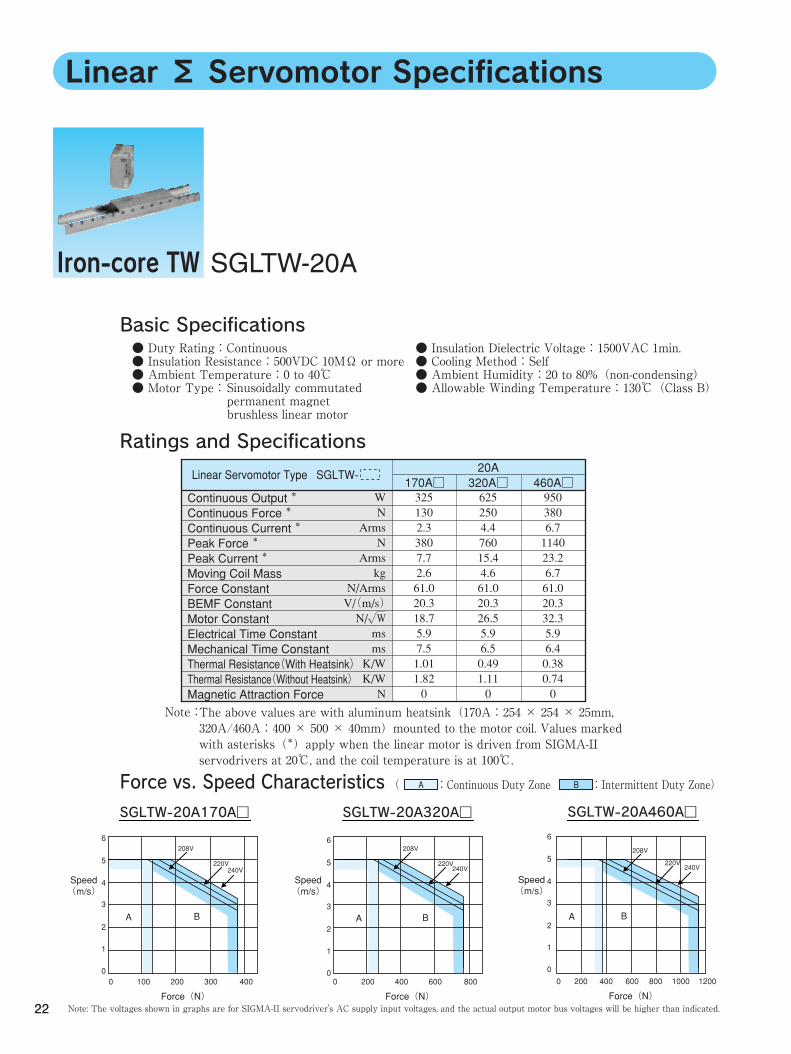
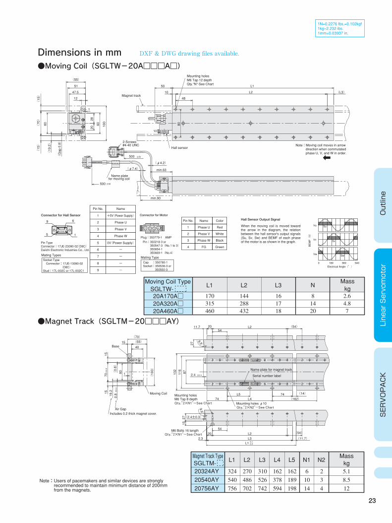
SGLTW-20A
Linear Σ Servomotor Specifications
Basic Specifications
The above values are with aluminum heatsink(170A:254 × 254 × 25mm, 320A/460A:400 × 500 × 40mm)mounted to the motor coil. Values marked with asterisks(*)apply when the linear motor is driven from SIGMA-II servodrivers at 20℃, and the coil temperature is at 100℃.
Ratings and Specifications
Note:
( :Continuous Duty Zone :Intermittent Duty Zone) A B
Note: The voltages shown in graphs are for SIGMA-II servodriver's AC supply input voltages, and the actual output motor bus voltages will be higher than indicated.
Force vs. Speed Characteristics
Iron-core TW
Linear Servomotor Type SGLTW- 170A□
20A 320A□
460A□
● Duty Rating:Continuous ● Insulation Resistance:500VDC 10MΩ or more ● Ambient Temperature:0 to 40℃ ● Motor Type:
● Insulation Dielectric Voltage:1500VAC 1min. ● Cooling Method:Self ● Ambient Humidity:20 to 80%(non-condensing) ● Allowable Winding Temperature:130℃(Class B) Sinusoidally commutated
permanent magnet brushless linear motor
325 130 2.3 380 7.7 2.6 61.0 20.3 18.7 5.9 7.5 1.01 1.82 0
W N
Arms N
Arms kg
N/Arms V/(m/s) N/√W ms ms K/W K/W N
625 250 4.4 760 15.4 4.6 61.0 20.3 26.5 5.9 6.5 0.49 1.11 0
950 380 6.7 1140 23.2 6.7 61.0 20.3 32.3 5.9 6.4 0.38 0.74 0
Continuous Output * Continuous Force * Continuous Current * Peak Force * Peak Current * Moving Coil Mass Force Constant BEMF Constant Motor Constant Electrical Time Constant Mechanical Time Constant Thermal Resistance(With Heatsink) Thermal Resistance(Without Heatsink) Magnetic Attraction Force
SGLTW-20A170A□ SGLTW-20A320A□ SGLTW-20A460A□
6
5
4
3
2
1
00 100 200 300 400
Speed (m/s)
Force(N)
A B
6
5
4
3
2
1
00 200 400 600 800
Speed (m/s)
Force(N)
A B
6
5
4
3
2
1
00 200 600400 800 1000 1200
Speed (m/s)
Force(N)
A B
208V
220V240V
208V
220V240V
208V
220V240V
23
Dimensions in mm
Outline
Linear Servomotor
SERVOPACK
●Moving Coil(SGLTW-20A□□□A□)
1N=0.2276 lbs.=0.102kgf 1kg=2.232 ibs. 1mm=0.03937 in.
Socket Type Connector:17JE-13090-02 (D8C) Stud:17L-002C or 17L-002C1
Pin No.
1
2
3
4
5
6
7
8
9
Name
+5V(Power Supply)
Phase U
Phase V
Phase W
0V(Power Supply)
-
-
-
-
Connector for Motor
Plug:350779-1 AMP
Pin:350218-3 or 350547-3(No.1 to 3) 350654-1 350669-1(No.4)
Mating TypeCap :350780-1 Socket:350536-3 or 350550-3
BEMF(V)
Electrical Angle(°)
Vu
Vv
Vw
Su
Sv
Sw
0 180 360 540
Connector for Hall Sensor
9 6
15
Pin Type Connector:17JE-23090-02(D8C) Daiichi Electronic Industries Co., Ltd.
Mating Types
Pin No.
1
2
3
4
Name
Phase U
Phase V
Phase W
FG
Color
Red
White
Black
Green
Hall Sensor Output Signal
When the moving coil is moved toward the arrow in the diagram, the relation between the hall sensor's output signals (Su, Sv, Sw) and BEMF of each phase of the motor is as shown in the graph.
Moving Coil Type SGLTW- 20A170A□ 20A320A□ 20A460A□
L1
170 315 460
L2
144 288 432
L3
16 17 18
N
8 14 20
Mass kg2.6 4.8 7
●Magnet Track(SGLTM-20□□□AY)
Magnet Track Type SGLTM- L1
20324AY 20540AY 20756AY
324 540 756
L2
270 486 702
L3
310 526 742
L4
162 378 594
L5
162 189 198
N1
6 10 14
N2
2 3 4
Mass kg5.1 8.5 12
Mounting holes
Qty.″2×N1″-See Chart Qty.″2×N2″-See Chart
Qty.″2×N1″-See Chart
Name plate for magnet track
M6 Bolts 16 length
M6 Tap 8 depthMounting holes φ10
Includes 0.2 thick magnet cover.
Moving Coil
Serial number label
Air Gap
Base
2715
(2.4±0.3)
132
11687
±0.32.4
L3
L4L5
(0.8)
±0.3
0.819.2
±0.3
70
-0.3-0.1L1
(11.7)
(54)
2.320
54L2
9.9゚
74 (14)
(162) 74
(54) 11.7 L254
20
279.9゚
160
1515
(100)
(70) (55)
4015
S/N
O/N
TYPE:MADE IN JAPANDATE
YASKAWA
S/N
O/N
TYPE: MADE IN JAPAN DATE
YASKAWA
Magnet track
Hall sensor
2-Screws
Mounting holesM6 Tap 12 depthQty."N"-See Chart
for moving coilName plate
#4-40 UNC
47.5
min.90
100
60
2820
(15)
(70)
(15)
(φ7.4)
(φ4.2)
min.63
50
±50500
(55)
±50500
12
51
(L3)
L1
80
1
10
48
L2
60(19.2)
(Gap 0.8)
Note:Moving coil moves in arrow direction when commutated phase U, V, and W in order.
Note:Users of pacemakers and similar devices are strongly recommended to maintain minimum distance of 200mm from the magnets.
DXF & DWG drawing files available.
24
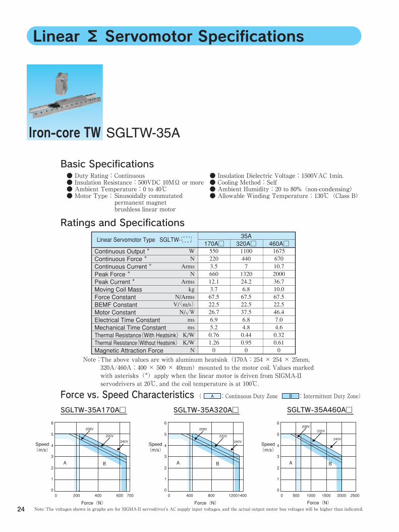
SGLTW-35A
Linear Σ Servomotor Specifications
Basic Specifications
The above values are with aluminum heatsink(170A:254 × 254 × 25mm, 320A/460A:400 × 500 × 40mm)mounted to the motor coil. Values marked with asterisks(*)apply when the linear motor is driven from SIGMA-II servodrivers at 20℃, and the coil temperature is at 100℃.
Ratings and Specifications
Note:
( :Continuous Duty Zone :Intermittent Duty Zone) A B
Note: The voltages shown in graphs are for SIGMA-II servodriver's AC supply input voltages, and the actual output motor bus voltages will be higher than indicated.
Force vs. Speed Characteristics
Iron-core TW
Linear Servomotor Type SGLTW- 170A□
35A 320A□
460A□
● Duty Rating:Continuous ● Insulation Resistance:500VDC 10MΩ or more ● Ambient Temperature:0 to 40℃ ● Motor Type:
● Insulation Dielectric Voltage:1500VAC 1min. ● Cooling Method:Self ● Ambient Humidity:20 to 80%(non-condensing) ● Allowable Winding Temperature:130℃(Class B) Sinusoidally commutated
permanent magnet brushless linear motor
550 220 3.5 660 12.1 3.7 67.5 22.5 26.7 6.9 5.2 0.76 1.26 0
W N
Arms N
Arms kg
N/Arms V/(m/s) N/√W ms ms K/W K/W N
1100 440 7 1320 24.2 6.8 67.5 22.5 37.5 6.8 4.8 0.44 0.95 0
1675 670 10.7 2000 36.7 10.0 67.5 22.5 46.4 7.0 4.6 0.32 0.61 0
Continuous Output * Continuous Force * Continuous Current * Peak Force * Peak Current * Moving Coil Mass Force Constant BEMF Constant Motor Constant Electrical Time Constant Mechanical Time Constant Thermal Resistance(With Heatsink) Thermal Resistance(Without Heatsink) Magnetic Attraction Force
SGLTW-35A170A□ SGLTW-35A320A□ SGLTW-35A460A□
6
5
4
3
2
1
00 200 400 600 700
Speed (m/s)
Force(N)
A B
Force(N)
208V
220V
240V
6
5
4
3
2
1
00 400 800 12001400
Speed (m/s)
Force(N)
A B
208V
220V
240V
6
5
4
3
2
1
00 500 20001000 1500 2500
Speed (m/s)
A B
208V220V
240V
25
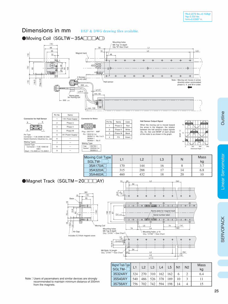
Dimensions in mm
Outline
Linear Servomotor
SERVOPACK
●Moving Coil(SGLTW-35A□□□A□)
1N=0.2276 lbs.=0.102kgf 1kg=2.232 ibs. 1mm=0.03937 in.
Moving Coil Type SGLTW- 35A170A□ 35A320A□ 35A460A□
L1
170 315 460
L2
144 288 432
L3
16 17 18
N
8 14 20
Mass kg3.7 6.8 10
●Magnet Track(SGLTM-20□□□AY)
Magnet Track Type SGLTM- L1
35324AY 35540AY 35756AY
324 540 756
L2
270 486 702
L3
310 526 742
L4
162 378 594
L5
162 189 198
N1
6 10 14
N2
2 3 4
Mass kg6.4 11 15
Socket Type Connector:17JE-13090-02 (D8C) Stud:17L-002C or 17L-002C1
Pin No.
1
2
3
4
5
6
7
8
9
Name
+5V(Power Supply)
Phase U
Phase V
Phase W
0V(Power Supply)
-
-
-
-
Connector for Motor
Plug:350779-1 AMP
Electrical Angle(°)
Vu
Vv
Vw
Su
Sv
Sw
0 180 360 540
Connector for Hall Sensor
9 6
15
Mating Types
Mating TypeCap :350780-1 Socket:350536-3 or 350550-3
Pin No.
1
2
3
4
Name
Phase U
Phase V
Phase W
FG
Color
Red
White
Black
Green
Pin:350218-3 or 350547-3(No.1 to 3) 350654-1 350669-1(No.4)
BEMF(V)
Pin Type Connector:17JE-23090-02(D8C) Daiichi Electronic Industries Co., Ltd.
Hall Sensor Output Signal
When the moving coil is moved toward the arrow in the diagram, the relation between the hall sensor's output signals (Su, Sv, Sw) and BEMF of each phase of the motor is as shown in the graph.
DXF & DWG drawing files available.
Magnet track
M6 Tap 12 depth
Hall sensor
Mounting holes
Qty."N"-See Chart
for moving coilName plate
#4-40 UNC2-Screws
55
min. 100
100
60
2820
(φ8.4)
(70)
66
12
(φ4.2)
±50500
50
60
min. 63
(70)
(19.2)
(15)
±50500
(L3)
L1
80
1
10
48
L2
(Gap 0.8)
(15)
Note:Moving coil moves in arrow direction when commutated phase U, V, and W in order.
Mounting holes
Qty.″2×N2″-See Chart
Qty.″2×N1″-See Chart
Qty.″2×N1″-See Chart
Name plate for magnet track
M6 Bolts 16 length
M6 Tap 8 depth Mounting holes φ10
Includes 0.2 thick magnet cover.
Serial number label
Air Gap
Base
34.5
15
(2.4±0.3)
(54)
9.9゚
±0.32.4
L5L4
L3
132
11687
±0.3
0.8
(0.8)
19.2
±0.3
70
(54)
9.9゚ 34.5
13 L254
20
(162) (14)
7474
1 (13) 20
54L2
-0.3-0.1L1
60
(100)
1555
(85) (70)
1
1515
Moving Coil
S/N
O/N
TYPE:MADE IN JAPANDATE
YASKAWA
S/N
O/N
TYPE: MADE IN JAPAN DATE
YASKAWA
Note:Users of pacemakers and similar devices are strongly recommended to maintain minimum distance of 200mm from the magnets.

26
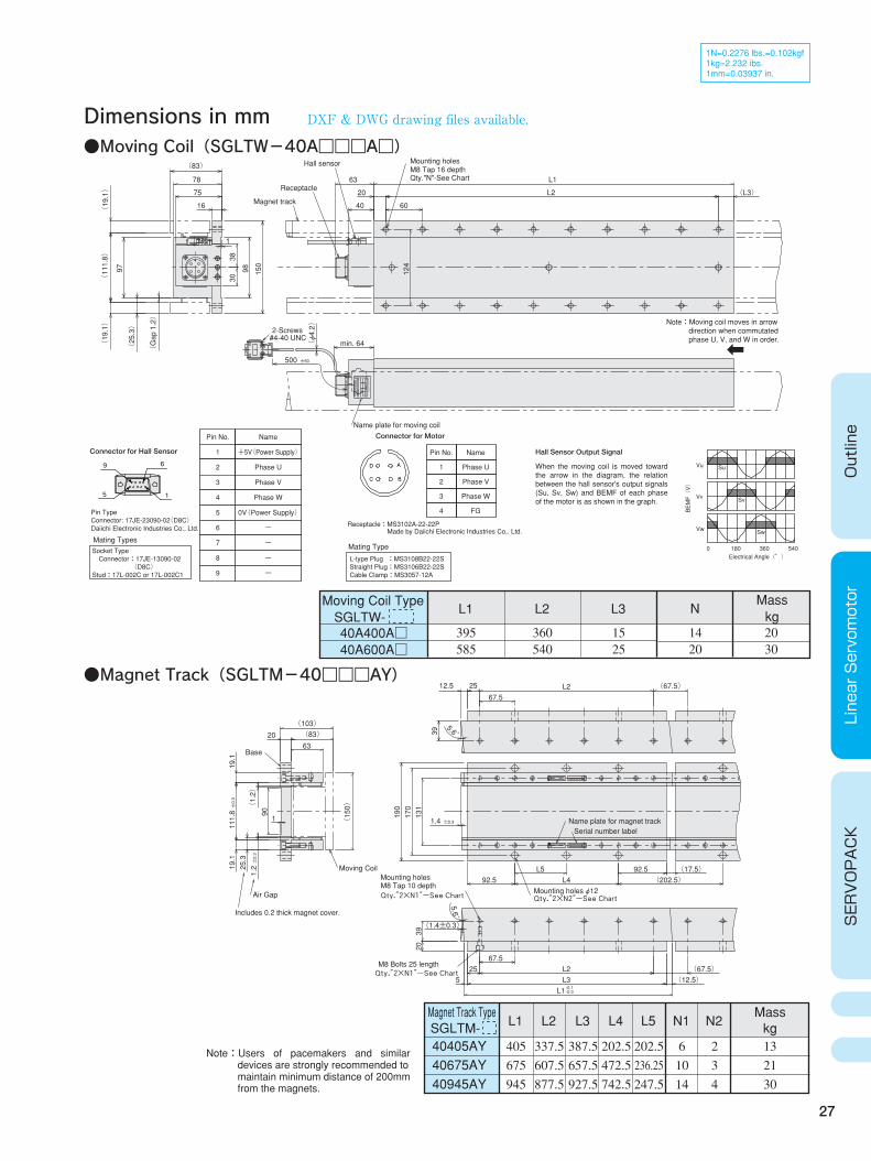
SGLTW-40A
Linear Σ Servomotor Specifications
Basic Specifications
Ratings and Specifications
( :Continuous Duty Zone :Intermittent Duty Zone) A B
Note: The voltages shown in graphs are for SIGMA-II servodriver's AC supply input voltages, and the actual output motor bus voltages will be higher than indicated.
Force vs. Speed Characteristics
Iron-core TW
The above values are with aluminum heatsink(609×762×50mm) mounted to the motor coil. Values marked with asterisks(*)apply when the linear motor is driven from SIGMA-II servodrivers at 20℃, and the coil temperature is at 100℃.
Note:
Linear Servomotor Type SGLTW- 400A□
600A□
40A
● Duty Rating:Continuous ● Insulation Resistance:500VDC 10MΩ or more ● Ambient Temperature:0 to 40℃ ● Motor Type:
● Insulation Dielectric Voltage:1500VAC 1min. ● Cooling Method:Self ● Ambient Humidity:20 to 80%(non-condensing) ● Allowable Winding Temperature:130℃(Class B) Sinusoidally commutated
permanent magnet brushless linear motor
SGLTW-40A400A□
Force(N)
6
5
4
3
2
1
00 500 20001000 1500 2500
Speed (m/s)
A B
208V
220V
240V
SGLTW-40A600A□
Force(N)
6
5
4
3
2
1
00 20001000 35003000
Speed (m/s)
A B
208V
220V
240V
1675 670 10.8 2000 37 20.0 66.9 22.3 64.1 17.8 4.9 0.34 0.60 0
W N
Arms N
Arms kg
N/Arms V/(m/s) N/√W ms ms K/W K/W N
2500 1000 16.1 3000 55.5 30.0 66.9 22.3 76.6 16.5 5.1 0.23 0.47 0
Continuous Output * Continuous Force * Continuous Current * Peak Force * Peak Current * Moving Coil Mass Force Constant BEMF Constant Motor Constant Electrical Time Constant Mechanical Time Constant Thermal Resistance(With Heatsink) Thermal Resistance(Without Heatsink) Magnetic Attraction Force
27
Dimensions in mm
Outline
Linear Servomotor
SERVOPACK
●Moving Coil(SGLTW-40A□□□A□)
1N=0.2276 lbs.=0.102kgf 1kg=2.232 ibs. 1mm=0.03937 in.
Moving Coil Type SGLTW- 40A400A□ 40A600A□
L1
395 585
L2
360 540
L3
15 25
N
14 20
Mass kg20 30
●Magnet Track(SGLTM-40□□□AY)
Magnet Track Type SGLTM- L1
40405AY 40675AY 40945AY
405 675 945
L2
337.5 607.5 877.5
L3
387.5 657.5 927.5
L4
202.5 472.5 742.5
L5
202.5 236.25 247.5
N1
6 10 14
N2
2 3 4
Mass kg13 21 30
Pin Type Connector: 17JE-23090-02(D8C) Daiichi Electronic Industries Co., Ltd.
Mating TypesSocket Type Connector:17JE-13090-02 (D8C) Stud:17L-002C or 17L-002C1
Pin No.
1
2
3
4
5
6
7
8
9
Name
+5V(Power Supply)
Phase U
Phase V
Phase W
0V(Power Supply)
-
-
-
-
Connector for Hall Sensor
9 6
15
Receptacle:MS3102A-22-22P Made by Daiichi Electronic Industries Co,. Ltd.
Mating Type
L-type Plug :MS3108B22-22S Straight Plug:MS3106B22-22S Cable Clamp:MS3057-12A
Connector for Motor
Pin No.
1
2
3
4
Name
Phase U
Phase V
Phase W
FG
Electrical Angle(°)
Vu
Vv
Vw
Su
Sv
Sw
0 180 360 540
Hall Sensor Output Signal
When the moving coil is moved toward the arrow in the diagram, the relation between the hall sensor's output signals (Su, Sv, Sw) and BEMF of each phase of the motor is as shown in the graph. B
EMF(V)
DXF & DWG drawing files available.
Magnet track
2-Screws#4-40 UNC
Name plate for moving coil
Receptacle
Hall sensorM8 Tap 16 depthMounting holes
Qty."N"-See Chart
±50500
Nm/s
Linear SERVO MOTOR
ins.DATE
S/NO/N
VA W
MADE IN JAPAN
YASKAWA ELECTRIC
TYPE
75
(φ4.2)
(83)
78
16
(L3) 20
63 L1
L2
40 60
min. 64
(19.1)
(111.8)
97
(Gap 1.2)
(25.3)
130
38
98 124
150
(19.1) Note:Moving coil moves in arrow
direction when commutated phase U, V, and W in order.
Mounting holes
Qty.″2×N2″-See Chart
Qty.″2×N1″-See Chart
Qty.″2×N1″-See Chart Mounting holes φ12
Name plate for magnet track
M8 Tap 10 depth
M8 Bolts 25 length
Includes 0.2 thick magnet cover.
Moving Coil
Serial number label
Air Gap
Base
(1.4±0.3)
-0.3-0.1L1
(12.5) L3525 L2 (67.5)
67.5
5.6゚
(202.5) 92.5 L4L5 92.5 (17.5)
170
190
131
2039
±0.31.4
(83) (103)
1
(1.2)
90
19.1
25.3
±0.3
111.8
±0.3
1.2
5.6゚ 39
12.5 25 (67.5)
67.5L2
6320
19.1
(150)
S/N
O/N
MADE IN JAPANDATE TYPE:YASKAWA
S/N
O/N
MADE IN JAPAN DATETYPE:YASKAWA
Note:Users of pacemakers and similar devices are strongly recommended to maintain minimum distance of 200mm from the magnets.
28
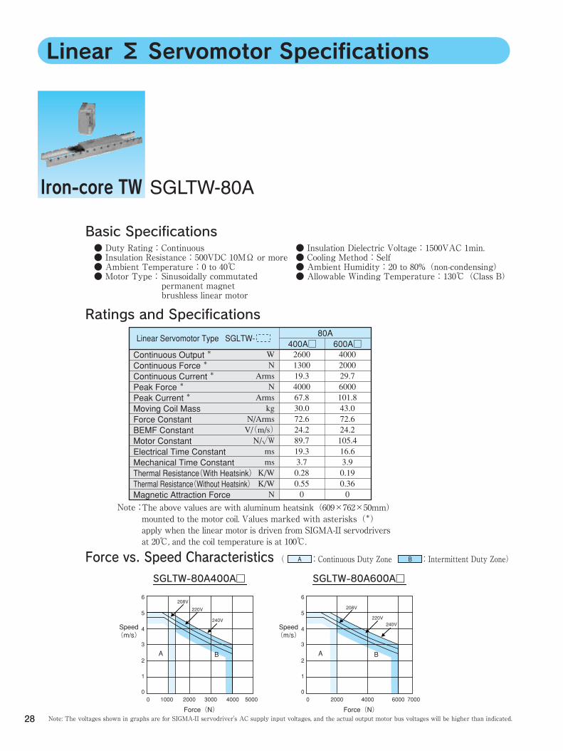
SGLTW-80A
Linear Σ Servomotor Specifications
Basic Specifications
Ratings and Specifications
( :Continuous Duty Zone :Intermittent Duty Zone) A B
Note: The voltages shown in graphs are for SIGMA-II servodriver's AC supply input voltages, and the actual output motor bus voltages will be higher than indicated.
Force vs. Speed Characteristics
Iron-core TW
The above values are with aluminum heatsink(609×762×50mm) mounted to the motor coil. Values marked with asterisks(*) apply when the linear motor is driven from SIGMA-II servodrivers at 20℃, and the coil temperature is at 100℃.
Note:
Linear Servomotor Type SGLTW- 400A□
600A□
80A
● Duty Rating:Continuous ● Insulation Resistance:500VDC 10MΩ or more ● Ambient Temperature:0 to 40℃ ● Motor Type:
● Insulation Dielectric Voltage:1500VAC 1min. ● Cooling Method:Self ● Ambient Humidity:20 to 80%(non-condensing) ● Allowable Winding Temperature:130℃(Class B) Sinusoidally commutated
permanent magnet brushless linear motor
SGLTW-80A400A□
Force(N)
6
5
4
3
2
1
00 1000 40002000 3000 5000
Speed (m/s)
A B
208V
220V
240V
SGLTW-80A600A□
Force(N)
6
5
4
3
2
1
00 40002000 70006000
Speed (m/s)
A B
208V
220V240V
2600 1300 19.3 4000 67.8 30.0 72.6 24.2 89.7 19.3 3.7 0.28 0.55 0
W N
Arms N
Arms kg
N/Arms V/(m/s) N/√W ms ms K/W K/W N
4000 2000 29.7 6000 101.8 43.0 72.6 24.2 105.4 16.6 3.9 0.19 0.36 0
Continuous Output * Continuous Force * Continuous Current * Peak Force * Peak Current * Moving Coil Mass Force Constant BEMF Constant Motor Constant Electrical Time Constant Mechanical Time Constant Thermal Resistance(With Heatsink) Thermal Resistance(Without Heatsink) Magnetic Attraction Force
29
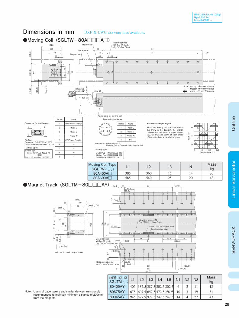
Dimensions in mm
Outline
Linear Servomotor
SERVOPACK
●Moving Coil(SGLTW-80A□□□A□)
1N=0.2276 lbs.=0.102kgf 1kg=2.232 ibs. 1mm=0.03937 in.
Moving Coil Type SGLTW- 80A400A□ 80A600A□
L1
395 585
L2
360 540
L3
15 25
N
14 20
Mass kg30 43
●Magnet Track(SGLTM-80□□□AY)
Magnet Track Type SGLTM- L1
80405AY 80675AY 80945AY
405 675 945
L2
337.5 607.5 877.5
L3
387.5 657.5 927.5
L4
202.5 472.5 742.5
L5
202.5 236.25 247.5
N1
6 10 14
N3
11 19 27
N2
2 3 4
Mass kg18 31 43
540
Mating TypesSocket Type Connector:17JE-13090-02 (D8C) Stud:17L-002C or 17L-002C1
Pin No.
1
2
3
4
5
6
7
8
9
Name
+5V(Power Supply)
Phase U
Phase V
Phase W
0V(Power Supply)
-
-
-
-
9 6
15
Receptacle:MS3102A-22-22P Made by Daiichi Electronic Industries Co,. Ltd.
Mating Type
L-type Plug :MS3108B22-22S Straight Plug:MS3106B22-22S Cable Clamp:MS3057-12A
Connector for Motor
Pin No.
1
2
3
4
Name
Phase U
Phase V
Phase W
FG
Electrical Angle(°)
Vu
Vv
Vw
Su
Sv
Sw
0 180 360 540
Pin Type Connector: 17JE-23090-02(D8C) Daiichi Electronic Industries Co., Ltd.
Connector for Hall Sensor Hall Sensor Output Signal
When the moving coil is moved toward the arrow in the diagram, the relation between the hall sensor's output signals (Su, Sv, Sw) and BEMF of each phase of the motor is as shown in the graph. B
EMF(V)
DXF & DWG drawing files available.
Note:Users of pacemakers and similar devices are strongly recommended to maintain minimum distance of 200mm from the magnets.
Magnet track
#4-40 UNC2-Screws
Name plate for moving coil
Receptacle
Hall sensor M8 Tap 16 depthMounting holes
Qty."N"-See Chart
±50500
75
(φ4.2)
(L3)
L1
L2
63
20
6040
(120)
115
16
min. 64
(25.3)
(Gap 1.2)
130
38
98 124
150
97
(19.1)
(111.8)
(19.1)
Nm/s
Linear SERVO MOTOR
ins.DATE
S/NO/N
VA W
MADE IN JAPAN
YASKAWA ELECTRIC
TYPE
Note:Moving coil moves in arrow direction when commutated phase U, V, and W in order.
M8 Bolts 25 lengthQty.″2×N3″-See Chart
Mounting holes
Qty.″2×N2″-See Chart
Qty.″2×N1″-See Chart
Moving Coil
Mounting holes φ12
Name plate for magnet track
M8 Tap 10 depth
Includes 0.2 thick magnet cover.
Serial number label
Air Gap
Base
67.533.75
(67.5) L22514.4
(17.5) (202.5) L492.5
92.5L5
33.75
(67.5) (14.4)
-0.3-0.1L1
3.1 L325 L2
67.5
2057
(1.5±0.3)
5.6゚
190
170
131
±0.31.5
(120) (140)
±0.3
1.2
(1.2)
25.3
±0.3
111.8
57
90
1
5.6゚
10020
19.1
19.1
(150)
S/N
O/N
MADE IN JAPANDATE TYPE:YASKAWA
S/N
O/N
MADE IN JAPAN DATETYPE:YASKAWA
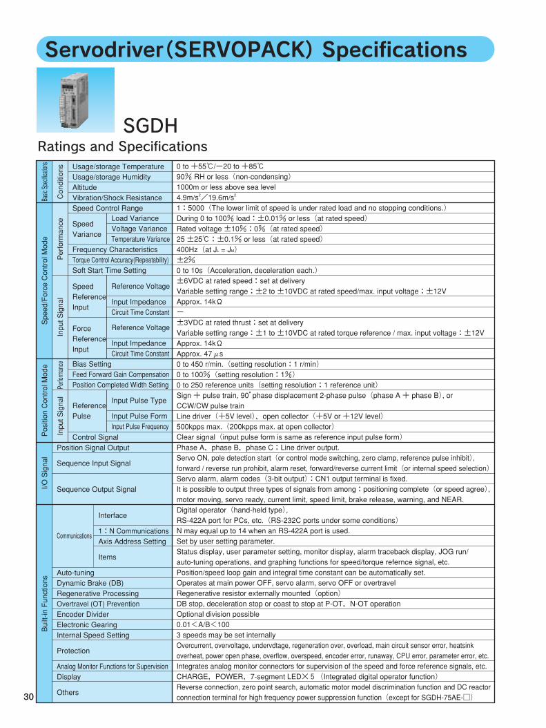
Servodriver(SERVOPACK)Specifications
30
Ratings and SpecificationsSGDH
0 to +55℃/-20 to +85℃ 90% RH or less(non-condensing) 1000m or less above sea level 4.9m/s2/19.6m/s2
1:5000(The lower limit of speed is under rated load and no stopping conditions.) During 0 to 100% load:±0.01% or less(at rated speed) Rated voltage ±10%:0%(at rated speed) 25 ±25℃:±0.1% or less(at rated speed) 400Hz(at JL = JM) ±2% 0 to 10s(Acceleration, deceleration each.) ±6VDC at rated speed:set at delivery Variable setting range:±2 to ±10VDC at rated speed/max. input voltage:±12V Approx. 14kΩ - ±3VDC at rated thrust:set at delivery Variable setting range:±1 to ±10VDC at rated torque reference / max. input voltage:±12V Approx. 14kΩ Approx. 47μs 0 to 450 r/min.(setting resolution:1 r/min) 0 to 100%(setting resolution:1%) 0 to 250 reference units(setting resolution:1 reference unit) Sign + pulse train, 90°phase displacement 2-phase pulse(phase A + phase B), or CCW/CW pulse train Line driver(+5V level),open collector(+5V or +12V level) 500kpps max.(200kpps max. at open collector) Clear signal(input pulse form is same as reference input pulse form) Phase A,phase B,phase C:Line driver output. Servo ON, pole detection start(or control mode switching, zero clamp, reference pulse inhibit), forward / reverse run prohibit, alarm reset, forward/reverse current limit(or internal speed selection) Servo alarm, alarm codes(3-bit output):CN1 output terminal is fixed. It is possible to output three types of signals from among:positioning complete(or speed agree), motor moving, servo ready, current limit, speed limit, brake release, warning, and NEAR. Digital operator(hand-held type), RS-422A port for PCs, etc.(RS-232C ports under some conditions) N may equal up to 14 when an RS-422A port is used. Set by user setting parameter. Status display, user parameter setting, monitor display, alarm traceback display, JOG run/ auto-tuning operations, and graphing functions for speed/torque refernce signal, etc. Position/speed loop gain and integral time constant can be automatically set. Operates at main power OFF, servo alarm, servo OFF or overtravel Regenerative resistor externally mounted(option) DB stop, deceleration stop or coast to stop at P-OT,N-OT operation Optional division possible 0.01<A/B<100 3 speeds may be set internally Overcurrent, overvoltage, undervdtage, regeneration over, overload, main circuit sensor error, heatsink overheat, power open phase, overflow, overspeed, encoder error, runaway, CPU error, parameter error, etc. Integrates analog monitor connectors for supervision of the speed and force reference signals, etc. CHARGE,POWER,7-segment LED×5(Integrated digital operator function) Reverse connection, zero point search, automatic motor model discrimination function and DC reactor connection terminal for high frequency power suppression function(except for SGDH-75AE-□)
Basic Specifications
Speed/Force Control Mode
Position Control Mode
I/O Signal
Built-in Functions
Conditions
Performance
Input Signal
Input SignalPerformance
Usage/storage Temperature Usage/storage Humidity Altitude Vibration/Shock Resistance Speed Control Range
Frequency Characteristics Torque Control Accuracy(Repeatability) Soft Start Time Setting
Bias Setting Feed Forward Gain Compensation Position Completed Width Setting
Position Signal Output
Sequence Input Signal
Sequence Output Signal
Communications
Auto-tuning Dynamic Brake (DB) Regenerative Processing Overtravel (OT) Prevention Encoder Divider Electronic Gearing Internal Speed Setting
Protection
Analog Monitor Functions for Supervision Display
Others
Control Signal
Load Variance Voltage Variance Temperature Variance
Reference Voltage
Input Impedance Circuit Time Constant
Speed Variance
Speed Reference Input
Reference Voltage
Input Impedance Circuit Time Constant
Input Pulse Type
Input Pulse Form Input Pulse Frequency
Force Reference Input
Reference Pulse
Interface
1:N Communications Axis Address Setting
Items
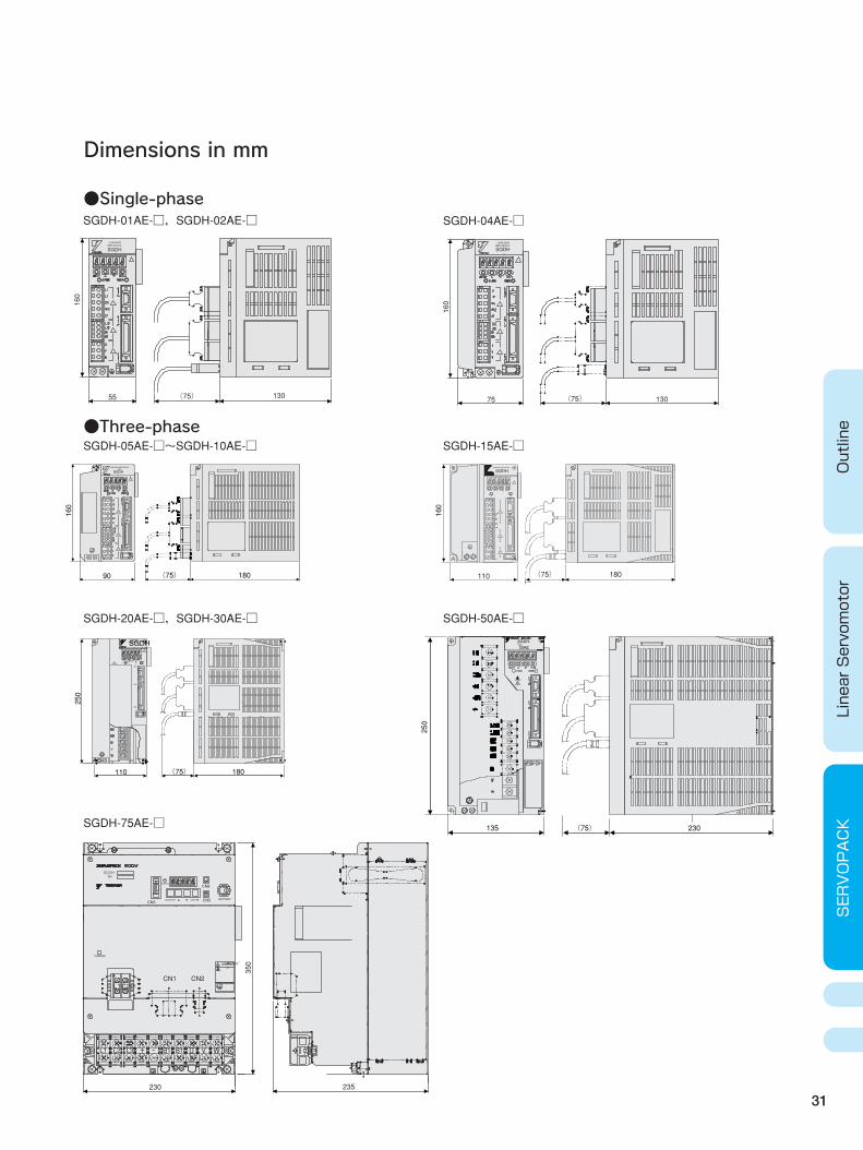
Dimensions in mm
●Single-phase
●Three-phase
31
Outline
Linear Servomotor
SERVOPACK
160
55 (75) 130
SGDH-01AE-□,SGDH-02AE-□ SGDH-04AE-□
SGDH-05AE-□~SGDH-10AE-□ SGDH-15AE-□
SGDH-20AE-□,SGDH-30AE-□
SGDH
160
75 (75) 130
CN3 CN5
CN8POWER
MODE/SET DATA/ BATTERY
CHARQE
L1C2CN2CN1
230
L1 L2 L3 + - B1 B1 U V W
350
235
160
160
90 (75) 180
250
110 (75) 180
SGDH
250
135 (75) 230
SGDH-50AE-□
SGDH-75AE-□
(75) 180
SGDHYASKAWA SERVOPACK
110
-
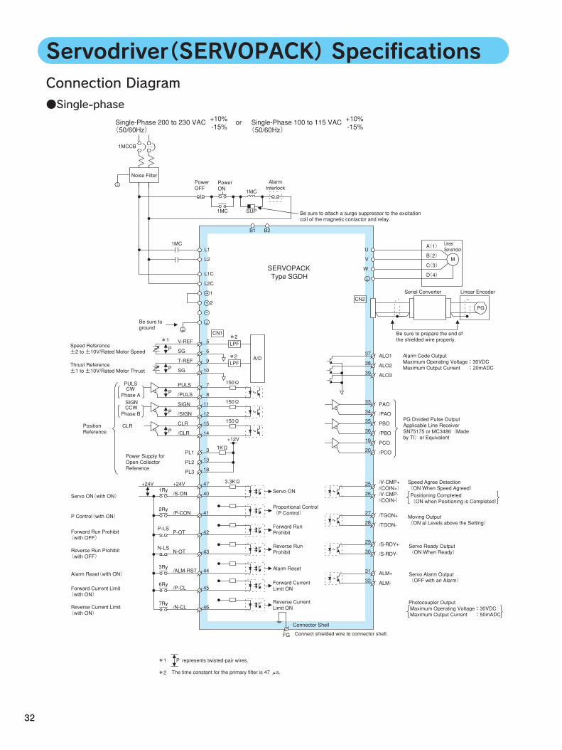
Connection Diagram●Single-phase
32
Servodriver(SERVOPACK)Specifications
150Ω
150Ω
L1
L2
L1C
L2C
1
2
CN1
V-REF
SG
5
6LPF
T-REF
SG
9
10LPF
P
P
A/D
PULS
/PULS
7
8
SIGN
/SIGN
11
12
P
P
CLR
/CLR
15
14P
150Ω
PL1 3
PL2
PL3
13
18
+12V
1KΩ
Speed Reference ±2 to ±10V/Rated Motor Speed
CLR
Power Supply for Open-Collector Reference
3.3KΩ +24V
/S-ON
47
401Ry Servo ON
/P-CON 412Ry Proportional Control
(P Control)
Forward Run Prohibit
Reverse Run Prohibit
Forward Current Limit ON
Reverse Current Limit ON
Alarm Reset
P-OT 42P-LS
N-OT 43N-LS
/ALM-RST 443Ry
/P-CL 456Ry
/N-CL 467Ry
+24V 25
26
/V-CMP+( / COIN+) /V-CMP-( / COIN-)
Speed Agree Detection (ON When Speed Agreed) Positioning Completed (ON when Positioning is Completed)
27
28/TGON+
/TGON-
29
30/S-RDY+
/S-RDY-
31
32ALM+
ALM-
37
38ALO1
ALO2
U
V
W
M
A( 1)
B( 2)
C( 3)
D( 4)
Linear EncoderSerial ConverterCN2
39 ALO3
33
34PAO
/PAO35
36PBO
/PBO19
20PCO
/PCO
1MC SUP
1MC
1MC
1MCCB
B1 B2
FG
*1 *2
*2
Single-Phase 200 to 230 VAC ( 50/60Hz)
+10%-15%
Single-Phase 100 to 115 VAC or( 50/60Hz)
+10%-15%
Power OFF
Power ON
Alarm Interlock
Be sure to attach a surge suppressor to the excitation coil of the magnetic contactor and relay.
SERVOPACKType SGDH
Be sure to ground
Thrust Reference ±1 to ±10V/Rated Motor Thrust
CWPhase A
PULS
CCWPhase B
SIGN
Position Reference
Servo ON(with ON)
P Control(with ON)
Forward Run Prohibit (with OFF)
Reverse Run Prohibit (with OFF)
Alarm Reset(with ON)
Forward Current Limit (with ON)
Reverse Current Limit (with ON)
Noise Filter
PG
The time constant for the primary filter is 47 μs.
P represents twisted-pair wires.*1
*2
Connector Shell
Connect shielded wire to connector shell.
Photocoupler Output Maximum Operating Voltage:30VDC Maximum Output Current :50mADC
Servo Ready Output (ON When Ready)
Servo Alarm Output (OFF with an Alarm)
Moving Output (ON at Levels above the Setting)
PG Divided Pulse Output Applicable Line Receiver SN75175 or MC3486(Made by TI)or Equivalent
Alarm Code Output Maximum Operating Voltage:30VDC Maximum Output Current :20mADC
Be sure to prepare the end of the shielded wire properly.
Linear Servomotor
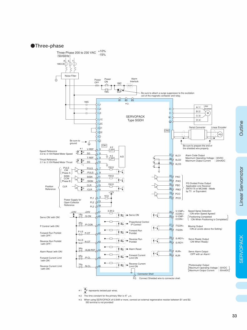
●Three-phase
33
Outline
Linear Servomotor
SERVOPACK
*3
SERVOPACKType SGDH
Speed Reference ±2 to ±10V/Rated Motor Speed
Be sure to ground
Thrust Reference ±1 to ±10V/Rated Motor Thrust
*1 *2
*2
CLR
Power Supply for Open-Collector Reference
CWPhase A
PULS
CCWPhase B
SIGN
Position Reference
Servo ON(with ON)
P Control(with ON)
Forward Run Prohibit (with OFF)
Reverse Run Prohibit (with OFF)
Alarm Reset(with ON)
Forward Current Limit (with ON)
Reverse Current Limit (with ON)
Servo ON
Proportional Control (P Control)
Forward Run Prohibit
Reverse Run Prohibit
Forward Current Limit ON
Reverse Current Limit ON
Alarm Reset
Speed Agree Detection (ON when Speed Agreed) Positioning Completed (ON When Positioning is Completed)
Linear EncoderSerial Converter
150Ω
150Ω
L1
L2
L1C
L2C
1
2
CN1
V-REF
SG
5
6LPF
T-REF
SG
9
10LPF
P
P
A/D
PULS
/PULS
7
8
SIGN
/SIGN
11
12
P
P
CLR
/CLR
15
14P
150Ω
PL1 3
PL2
PL3
13
18
+12V
1KΩ
3.3KΩ +24V
/S-ON
47
401Ry
/P-CON 412Ry
P-OT 42P-LS
N-OT 43N-LS
/ALM-RST 443Ry
/P-CL 456Ry
/N-CL 467Ry
+24V 25
26
/V-CMP+( / COIN+) /V-CMP-( / COIN-)
27
28/TGON+
/TGON-
29
30/S-RDY+
/S-RDY-
31
32ALM+
ALM-
37
38ALO1
ALO2
U
V
W
M
A( 1)
B( 2)
C( 3)
D( 4)
PG
CN2
39 ALO3
33
34PAO
/PAO35
36PBO
/PBO19
20PCO
/PCO
1MC SUP
1MC
1MC
1MCCB
B1 B2
FG
L3
R S T
B3
*1
Photocoupler Output Maximum Operating Voltage:30VDC Maximum Output Current :50mADC
Three-Phase 200 to 230 VAC ( 50/60Hz)
+10%-15%
Noise Filter
Power OFF
Power ON
Alarm Interlock
Be sure to attach a surge suppressor to the excitation coil of the magnetic contactor and relay.
The time constant for the primary filter is 47 μs.
P represents twisted-pair wires.*1
*2
When using SERVOPACK of 6.0kW or more, connect an external regenerative resistor between B1 and B2. (B3 terminal is not provided)
*3
Connector Shell
Connect Shielded wire to connector shell.
Servo Ready Output (ON When Ready)
Servo Alarm Output (OFF with an Alarm)
Moving Output (ON at Levels above the Setting)
PG Divided Pulse Output Applicable Line Receiver SN75175 or MC3486(Made by TI)or Equivalent
Alarm Code Output Maximum Operating Voltage:30VDC Maximum Output Current :20mADC
Be sure to prepare the end of the shielded wire properly.
Linear Servomotor
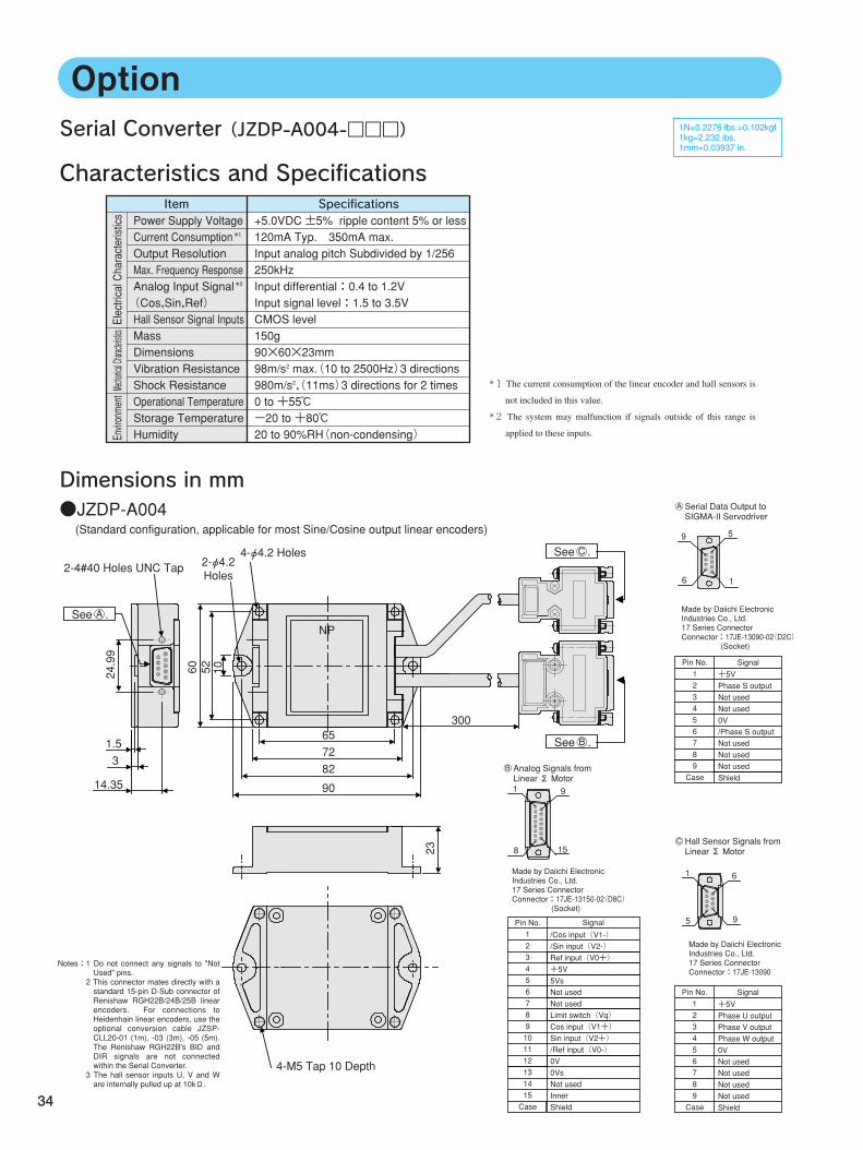
OptionSerial Converter(JZDP-A004-□□□)
Characteristics and Specifications
Dimensions in mm
Power Supply Voltage Current Consumption *1
Output Resolution Max. Frequency Response Analog Input Signal *2
(Cos,Sin,Ref) Hall Sensor Signal Inputs Mass Dimensions Vibration Resistance Shock Resistance Operational Temperature Storage Temperature Humidity
+5.0VDC ±5% ripple content 5% or less 120mA Typ. 350mA max. Input analog pitch Subdivided by 1/256 250kHz Input differential:0.4 to 1.2V Input signal level:1.5 to 3.5V CMOS level 150g 90×60×23mm 98m/s2 max.(10 to 2500Hz)3 directions 980m/s2,(11ms)3 directions for 2 times 0 to +55℃ -20 to +80℃ 20 to 90%RH(non-condensing)
Electrical Characteristics
Mechanical Characteristics
Environment
Item Specifications
*1 The current consumption of the linear encoder and hall sensors is
not included in this value.
*2 The system may malfunction if signals outside of this range is
applied to these inputs.
Notes:1 Do not connect any signals to "Not Used" pins. 2 This connector mates directly with a standard 15-pin D-Sub connector of Renishaw RGH22B/24B/25B linear encoders. For connections to Heidenhain linear encoders, use the optional conversion cable JZSP-CLL20-01 (1m), -03 (3m), -05 (5m). The Renishaw RGH22B's BID and DIR signals are not connected within the Serial Converter. 3 The hall sensor inputs U, V and W are internally pulled up at 10kΩ.
1N=0.2276 lbs.=0.102kgf 1kg=2.232 ibs. 1mm=0.03937 in.
24.99
1.53
14.35
●JZDP-A004(Standard configuration, applicable for most Sine/Cosine output linear encoders)
60 52 10
NP
657282
90
300
23
9 5
6 1
Pin No. 1 2 3 4 5 6 7 8 9 Case
+5V Phase S output Not used Not used 0V /Phase S output Not used Not used Not used Shield
Signal
1 6
5 9
Pin No. 1 2 3 4 5 6 7 8 9 Case
+5V Phase U output Phase V output Phase W output 0V Not used Not used Not used Not used Shield
Signal
1 9
8 15
Pin No. 1 2 3 4 5 6 7 8 9 10 11 12 13 14 15 Case
/Cos input(V1-) /Sin input(V2-) Ref input(V0+) +5V 5Vs Not used Not used Limit switch(Vq) Cos input(V1+) Sin input(V2+) /Ref input(V0-) 0V 0Vs Not used Inner Shield
Signal
NP
2-4#40 Holes UNC Tap
See .○ A
4-φ4.2 Holes2-φ4.2 Holes
See .○ B
See .○ C
4-M5 Tap 10 Depth
Made by Daiichi Electronic Industries Co., Ltd. 17 Series Connector Connector:17JE-13090-02(D2C) (Socket)
○ A Serial Data Output to SIGMA-II Servodriver
Analog Signals from Linear Σ Motor
○ B
Made by Daiichi Electronic Industries Co., Ltd. 17 Series Connector Connector:17JE-13150-02(D8C) (Socket)
Made by Daiichi Electronic Industries Co., Ltd. 17 Series Connector Connector:17JE-13090
Hall Sensor Signals from Linear Σ Motor
○ C
34
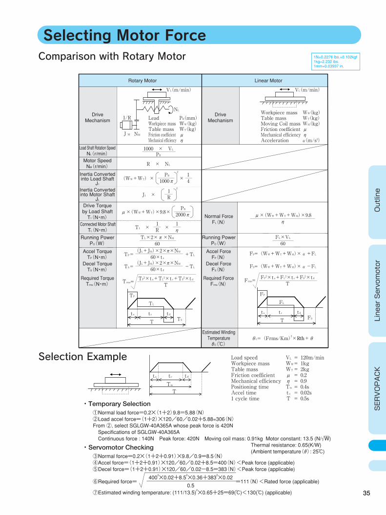
Selecting Motor Force
35
Outline
Linear Servomotor
SERVOPACK
1N=0.2276 lbs.=0.102kgf 1kg=2.232 ibs. 1mm=0.03937 in.
J M
J1 ×
2
R1
NL
NM
Comparison with Rotary Motor
Drive Mechanism
Rotary Motor Linear Motor
Load Shaft Rotation Speed NL(r/min) Motor Speed NM(r/min)
Inertia Converted into Load Shaft
J1
Drive Torque by Load Shaft T1(N・m) Normal Force
FL(N)
Running Power PO(W)
Estimated Winding Temperature θC(℃)
Connected Motor Shaft TL(N・m)
Accel Torque TP(N・m) Decel Torque TS(N・m)
Required Torque Trms(N・m)
Accel Force FP(N)
Decel Force FS(N)
Required Force Frms(N)
Running Power PO(W)
Inertia Converted into Motor Shaft
JL
Drive Mechanism
Workpiece mass Table mass Moving Coil mass Friction coefficient Mechanical efficiency Acceleration
WW(kg) WT(kg) WM(kg) μ η α(m/s2)
Lead Workpiece mass Table mass Friction coefficient Mechanical efficiency
PB(mm) WW(kg) WT(kg) μ η
VL(m/min) VL(m/min)
1/R
1000 × VL
R × NL
(WW+WT)× ×
2
PB
1000π PB
41
μ×(WW+WT)×9.8× μ×(WW+WT+WM)×9.8
FP=(WW+WT+WM)×α+FL
θC=(Frms/Km)2×Rth+θ
FS=(WW+WT+WM)×α-FL
η 2000π PB
FL×VL60
T1 × × R1
TP= +TL60×ta(JL+JM)×2×π×NM
TS=
TP
TST
TL
ta t c t d
FP
FST
FL
ta t c t d
-TL60×td(JL+JM)×2×π×NM
TTrms=
TP2×ta+TL2×tc+TS2×td
60TL×2×π×NM
η 1
TFrms=
FP2×ta+FL2×tc+FS2×td
Selection Example
TmT
ta t c t d
Load speed Workpiece mass Table mass Friction coefficient Mechanical efficiency Positioning time Accel time 1 cycle time
VL = 120m/min WW = 1kg WT = 2kg μ = 0.2 η = 0.9 Tm = 0.4s t a = 0.02s T = 0.5s
①Normal load force=0.2×(1+2)9.8=5.88(N) ②Load accel force=(1+2)×120/60/0.02+5.88=306(N) From ②, select SGLGW-40A365A whose peak force is 420N Specifications of SGLGW-40A365A Continuous force : 140N Peak force: 420N Moving coil mass: 0.91kg Motor constant: 13.5 (N/ W)
・Temporary Selection
③Normal force=0.2×(1+2+0.91)×9.8/0.9=8.5(N) ④Accel force=(1+2+0.91)×120/60/0.02+8.5=400(N)<Peak force (applicable) ⑤Decel force=(1+2+0.91)×120/60/0.02-8.5=383(N)<Peak force (applicable) ⑥Required force= =111(N)<Rated force (applicable)
⑦Estimated winding temperature: (111/13.5)2×0.65+25=69(℃)<130(℃) (applicable)
・Servomotor Checking
4002×0.02+8.5
2×0.36+383
2×0.02
0.5
Thermal resistance: 0.65(K/W) (Ambient temperature(θ): 25℃)
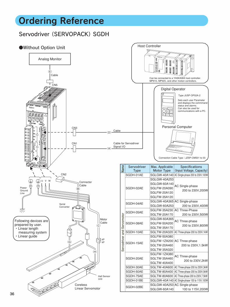
Servodriver(SERVOPACK)SGDH
36
●Without Option Unit
Following devices are prepared by user. ・Linear length measuring system ・Linear guide
Digital Operator
Sets each user Parameter and displays the commmand status and alarms. Can also be used for communications with a PC.
MP910, MP920, and other motion controllers.
Personal Computer
Host Controller
Connection Cable Type:JZSP-CMS01 to 03
Type JUSP-OP02A-2
CN3
CN1
CN2 SGLGW-40A140 SGLGW-40A253 SGLGW-60A140 SGLFW-20A090 SGLFW-20A120 SGLFW-35A120 SGLGW-40A365 SGLGW-60A253 SGLFW-35A230 SGLTW-20A170 SGLGW-60A365 SGLFW-50A200 SGLTW-35A170 SGLTW-20A320 SGLFW-50A380 SGLFW-1ZA200 SGLTW-20A460 SGLTW-35A320 SGLFW-1ZA380 SGLTW-35A460 SGLTW-40A400 SGLTW-40A600 SGLTW-80A400 SGLTW-80A600 SGLGW-40A140 SGLGW-40A253 SGLGW-60A140
AC Single-phase 200 to 230V,100W
AC Single-phase 200 to 230V,200W
AC Single-phase 200 to 230V,400W AC Three-Phase 200 to 230V,500W
AC Three-phase 200 to 230V,800W
AC Three-phase 200 to 230V,1kW AC Three-phase 200 to 230V,1.5kW AC Three-phase 200 to 230V,2kW AC Three-phase 200 to 230V,3kW AC Three-phase 200 to 230V,5kW AC Three-phase 200 to 230V,7.5kW AC Single-phase 100 to 115V,100W AC Single-phase 100 to 115V,200W
SGDH-01AE SGDH-02AE
SGDH-04AE SGDH-05AE
SGDH-08AE SGDH-10AE
SGDH-15AE
SGDH-20AE SGDH-30AE SGDH-50AE SGDH-75AE SGDH-01BE
SGDH-02BE
Power Ground Line
U V W
4P4P
Serial Converter
CN5
Cable
Analog Monitor
Ordering Reference
Can be connected to a YASKAWA host controller.
Coreless Linear Servomotor
Hall Sensor Unit
Servodriver and Servomotor
Name Servodriver
TypeMax. ApplicableMotor Type
Specifications(Input Voltage, Capacity)
(E)
Cable
Cable for Servodriver Signal I/O
(D)
(A)
Connector Cable
(B)
Motor Cable
(C)
(G)
(H)
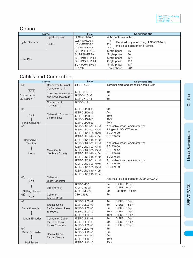
37
Outline
Linear Servomotor
SERVOPACK
1N=0.2276 lbs.=0.102kgf 1kg=2.232 ibs. 1mm=0.03937 in.
Name Type Specifications
Specifications
A 1m cable is attached. 1m 2m 3m Single-phase 5A Single-phase 8A Single-phase 10A Single-phase 15A Single-phase 20A Three-phase 20A
JUSP-OP02A-2 JZSP-CMS00-1 JZSP-CMS00-2 JZSP-CMS00-3 SUP-P5H-EPR-4 SUP-P8H-EPR-4 SUP-P10H-EPR-4 SUP-P15H-EPR-4 SUP-P20H-EPR-4 LF3200
Digital Operator Noise Filter
Name
Option
Cables and ConnectorsType
Connector Terminal Conversion Unit Cable with connector on only Servodriver Side
Connector Kit (for CN1)
Cable with Connectors on Both Ends
Motor Cable (for Main Circuit) Cable for Digital Operator Cable for PC Cable for Analog Monitor
Special Cable for Renishaw Linear Encoders Conversion Cable for Heidenhain Linear Encoders
Special Cable for Hall Sensor
Terminal block and connection cable 0.5m 1m 2m 3m 3m 5m 10m 15m 20m Applicable linear Servomotor type All types in SGLGW series SGLFW-20 SGLFW-35 Applicable linear Servomotor type SGLFW-50 SGLFW-1Z SGLTW-20 SGLTW-35 Applicable linear Servomotor type SGLTW-40 SGLTW-80 Attached to digital operator (JUSP-OP02A-2)
2m D-SUB 25-pin 2m D-SUB 9-pin 2m Half pitch 14-pin 1m 1m 3m 5m 10m 15m 1m 3m 5m 1m 3m 5m 10m 15m
JUSP-TA50P JZSP-CK101-1 JZSP-CK101-2 JZSP-CK101-3 JZSP-CK19 JZSP-CLP20-03 JZSP-CLP20-05 JZSP-CLP20-10 JZSP-CLP20-15 JZSP-CLP20-20 JZSP-CLN11-01(1m) JZSP-CLN11-03(3m) JZSP-CLN11-05(5m) JZSP-CLN11-10(10m) JZSP-CLN11-15(15m) JZSP-CLN21-01(1m) JZSP-CLN21-03(3m) JZSP-CLN21-05(5m) JZSP-CLN21-10(10m) JZSP-CLN21-15(15m) JZSP-CLN39-01(1m) JZSP-CLN39-03(3m) JZSP-CLN39-05(5m) JZSP-CLN39-10(10m) JZSP-CLN39-15(15m)
-
JZSP-CMS01 JZSP-CMS02 JZSP-CMS03 DE9404559 JZSP-CLL00-01 JZSP-CLL00-03 JZSP-CLL00-05 JZSP-CLL00-10 JZSP-CLL00-15 JZSP-CLL20-01 JZSP-CLL20-03 JZSP-CLL20-05 JZSP-CLL10-01 JZSP-CLL10-03 JZSP-CLL10-05 JZSP-CLL10-10 JZSP-CLL10-15
(A) Connector for I/O Signals (B) Serial Converter (C) Servodriver Terminal Motor (D) Setting Device (E) (G) Serial Converter Linear Encoder (H) Serial Converter Hall Sensor
Digital Operator Cable
CN5
CN3
↑↓
↑↓
↑↓
↑↓
CN2↑↓
CN1
Required only when using JUSP-OP02A-1, the digital operator for Σ Series.
D-SUB 15-pin D-SUB 15-pin D-SUB 15-pin D-SUB 15-pin D-SUB 15-pin D-SUB 15-pin D-SUB 15-pin D-SUB 15-pin
SERIESLinear
IRUMA BUSINESS CENTER480, Kamifujisawa, Iruma, Saitama 358-8555, JapanPhone 81-42-962-5696 Fax 81-42-962-6138
YASKAWA ELECTRIC AMERICA, INC.2121 Norman Drive South, Waukegan, IL 60085, U.S.A.Phone 1-847-887-7000 Fax 1-847-887-7370
MOTOMAN INC. HEADQUARTERS805 Liberty Lane West Carrollton, OH 45449, U.S.A.Phone 1-937-847-6200 Fax 1-937-847-6277
YASKAWA ELETRICO DO BRASIL COMERCIO LTD.A.Avenida Fagundes Filho, 620 Bairro Saude-Sao Paulo-SP, Brazil CEP: 04304-000Phone 55-11-5071-2552 Fax 55-11-5581-8795
YASKAWA ELECTRIC EUROPE GmbHAm Kronberger Hang 2, 65824 Schwalbach, GermanyPhone 49-6196-569-300 Fax 49-6196-569-312
Motoman Robotics Europe ABBox 504 S38525 Torsas, SwedenPhone 46-486-48800 Fax 46-486-41410
Motoman Robotec GmbHKammerfeldstraβe 1, 85391 Allershausen, GermanyPhone 49-8166-90-100 Fax 49-8166-90-103
YASKAWA ELECTRIC UK LTD.1 Hunt Hill Orchardton Woods Cumbernauld, G68 9LF, United KingdomPhone 44-1236-735000 Fax 44-1236-458182
YASKAWA ELECTRIC KOREA CORPORATIONKfpa Bldg #1201, 35-4 Youido-dong, Yeongdungpo-Ku, Seoul 150-010, KoreaPhone 82-2-784-7844 Fax 82-2-784-8495
YASKAWA ELECTRIC (SINGAPORE) PTE. LTD.151 Lorong Chuan, #04-01, New Tech Park Singapore 556741, SingaporePhone 65-6282-3003 Fax 65-6289-3003
YASKAWA ELECTRIC (SHANGHAI) CO., LTD.No.18 Xizang Zhong Road. Room 1805, Harbour Ring Plaza Shanghai 20000, ChinaPhone 86-21-5385-2200 Fax 86-21-5385-3299
YATEC ENGINEERING CORPORATION4F., No.49 Wu Kong 6 Rd, Wu-Ku Industrial Park, Taipei, TaiwanPhone 886-2-2298-3676 Fax 886-2-2298-3677
YASKAWA ELECTRIC (HK) COMPANY LIMITEDRm. 2909-10, Hong Kong Plaza, 186-191 Connaught Road West, Hong KongPhone 852-2803-2385 Fax 852-2547-5773
BEIJING OFFICERoom No. 301 Office Building of Beijing International Club, 21Jianguomenwai Avenue, Beijing 100020, ChinaPhone 86-10-6532-1850 Fax 86-10-6532-1851
TAIPEI OFFICE9F, 16, Nanking E. Rd., Sec. 3, Taipei, TaiwanPhone 886-2-2502-5003 Fax 886-2-2505-1280
SHANGHAI YASKAWA-TONGJI M & E CO., LTD.27 Hui He Road Shanghai China 200437Phone 86-21-6553-6060 Fax 86-21-5588-1190
BEIJING YASKAWA BEIKE AUTOMATION ENGINEERING CO., LTD.30 Xue Yuan Road, Haidian, Beijing P.R. China Post Code: 100083Phone 86-10-6233-2782 Fax 86-10-6232-1536
SHOUGANG MOTOMAN ROBOT CO., LTD.7, Yongchang-North Street, Beijing Economic Technological Investment & Development Area, Beijing 100076, P.R. ChinaPhone 86-10-6788-0551 Fax 86-10-6788-2878
YASKAWA ELECTRIC CORPORATION
Printed in Japan January 2004 01-3
LITERATURE NO. KAE-S800-39.10
03-10④
In the event that the end user of this product is to be the military and said product is to be employed in any weapons systems or the manufacture thereof, the export will fall under the relevant regulations as stipulated in the Foreign Exchange and Foreign Trade Regulations. Therefore, be sure to follow all procedures and submit all relevant documentation according to any and all rules, regulations and laws that may apply.
Specifications are subject to change without notice for ongoing product modifications and improvements.
© 2002-2004 YASKAWA ELECTRIC CORPORATION. All rights reserved.
YASKAWA