lenticular image generator for printing directly … · various dynamic effects: flip, motion,...
TRANSCRIPT

TRIAXES® LEGEND™ LENTICULAR IMAGE GENERATOR FOR PRINTING
DIRECTLY ONTO A LENS
USER GUIDE
Triaxes Lab Ltd., Tomsk, Russia
Web-site: www.triaxes.com
Technical support: [email protected]
Copyright© 2002-2014 Polyakov A.
Copyright© 2004-2014 Triaxes Lab Ltd.

1. Preface
1.1 Triaxes Legend Mission
Triaxes Legend encodes stereo images to be viewed by a number of various viewing methods. The encoding means “cutting” frames into thin stripes and mixing them in such a way that a pair of stripes is located under each lens: one from the first image and the other from the second one.
Triaxes Legend generates images for direct printing onto a lenticular lens. 3D images produced with this method can be viewed without special glasses or any additional devices.
The program allows you to produce lenticular images with various dynamic effects: flip, motion, morphing, zoom.
Besides, you can use the program to create a sequence of frames out of a single source image and a multilayer template.
The general procedure of creating stereo images of any type includes several steps:
● opening the sequence of frames
● adjusting their relative positions and cropping
● specifying parameters and generating a stereo image
● printing an image.
The program also allows you to apply various additional design elements (logos, frames,
labels, etc) onto final encoded images.
1.2 Triaxes Legend Editions
Editions Print
45 Print
90 Print 180
Pro
Number of frames 256 256 256 256
LPI 10-150 10-150 10-150 10-150
Max length of the biggest side, cm 45 90 180 3600
Resolution of generated images (PPI) 7200 7200 7200 7200
Image partitioning and encoding part by part
Transparency support
Mirroring
Positioning frame
Hardware key for software protection
The information about new versions is published on the www.triaxes.com and sent to Triaxes news subscribers.

Effects Frames series creation
Layered 3D
Any graphical editor Layered 3D with depth map for
each layer
Flip
Multiview 3D
Multiview shooting and 3D modeling software
Stereo pair-to-2D+Z or 2D+Z-to-N-view is performed by Triaxes StereoTracer
Animation Cutting frames from video or graphic editors
Fade
Frames series are created by morphing software
Morphing
Additional info
Tech support Free technical support by phone, email or skype
Updates Free updates during a year after purchasing
1.3 System requirements
IBM – compatible PC.
Operating system: Windows XP/Vista/7/8 (Windows 7/8 is recommended)
RAM: 1 Gb (preferably 2 Gb and more).
Free disk space: 150 Mb for software installation. When working with the large images (large data volume), additional space will be required for allocating service files and images created during work with the software.
1.4 32 or 64-bit?
We have 32-bit and 64-bit Triaxes Legend software versions. The main advantage of the 64-bit version is an opportunity to use more than 3 Gb of RAM compared to a 32-bit system, which assigns only 2 of 3 Gb for applications work. There can be not enough RAM to process up all frames.

1.5 Triaxes Legend demo version
Demo version of Triaxes Legend has the following limitations:
Generated images have a semi-transparent watermark: “Triaxes Legend DEMO www.triaxes.com”.
It is prohibited to sell Triaxes Legend demo-version to distribute it as a part of any other software product without written consent of copyright holders.
Note: In accordance with the Triaxes Legend license agreement, demo version may be used without time limitations.
1.6 Triaxes Legend activation
It is necessary to activate Triaxes Legend program in order to use it in a full functional mode. It allows you to get technical support and information about updates. One should get a Dongle (USB key) after the software purchase to activate the software. Until activated, the program will run in a demo mode.
To perform activation, do the following steps:
1. Plug a (hardware protection key in a USB port.
2. Run the software.
3. Run the command Help >> Activation.
4. In the Activation dialog click Open key… and select txt activation file received from the software vendor after purchasing.
5. Press Activate to complete the process.
Fig.1.1. Activation dialog
After activation is completed the About Legend dialog (Help >> About) will display the user information.

Fig.1.2. About Legend dialog
1.7 Triaxes Legend program update & upgrade policy
Free updates of all Triaxes Legend editions are available during the year from the purchase date. The update subscription is just the 10% of price. To upgrade to higher edition just cover the current price difference. Contact [email protected] for further information.
1.8 Technical support
Please contact your supplier for technical support questions. Besides, there is an opportunity to get help by contacting [email protected]. When addressing your technical request, please specify your activation user name, hardware key serial number, and program edition or just attach your txt activation file.
The web-site http://triaxes.com contains news on the Triaxes Legend software and updates to download. It also provides useful articles on the theory of stereo-lenticular technology and Triaxes Legend operation, distributors and lenticular materials suppliers contact info, as well as answers to frequently asked questions (FAQ).
Contacts:
E-mail: mailto:[email protected]
Skype: triaxes
Address: 634055, 3 Razvitiya Ave., Tomsk, Russia
Tel: +7 (3822) 701429
When submitting your request, please indicate the following:
1) Your name
2) Your e-mail
3) Your phone number
4) The distributor you purchased Triaxes Legend software from
5) The purchase date of Triaxes Legend software

2. Triaxes Legend Use
2.1 Triaxes Legend Main Window
Fig.2.1. General view of the program
1 – Menu line
2 – Main toolbar
3 – Toolbar
4 – Tabs of the Navigator window
5 – Sequence of frames
6 – Layers window
7 – Layers list
8 – Image display area (working area)
9 – Status bar
Detailed description of elements is provided below.
2.2 Navigator window
The Navigator window is to control projects and create images of various types.
Fig.2.2. Navigator window

Navigator window is located at the upper part of the Triaxes Legend window and contains the following tabs:
● Frames tab is used to manage source images
Image miniatures are displayed as the list here when downloading sequence of frames into a project or generating series of frames out of a layers set.
● Lenticular tab is used to manage parameters of lenticular encoding
In the upper part of the Navigator window there is an additional toolbar to manage viewing modes and source frames sorting.
You can either show or hide the Navigator window using the View >> Navigator window in the menu or with the hotkeys Ctrl+G..
Note: working with lists in Triaxes Legend program is similar to working with Windows lists – for mouse group selection use Shift key, for mouse direct selection use Ctrl key.
Useful tip: to “play” frames in turn in order to define perspective of a scene or flip effect, do the following:
1. Set the far right image as Right frame. Click the right mouse button on them and choose Set right.
2. Move slider to the right to make visible only the image marked as Right frame.
3. Press Ctrl + left/right arrow buttons to toggle current image in the frames list.
As a result the frames will be displayed in turn in the main program window. That tool is very useful to manage the movement speed and direction manually.
You can also play the sequence of source frames using the Animation button.
Fig.2.3. Animation button in the toolbar

2.3 Layers window
The Layers window is used to produce multilayer stereo images as well as to put generated images (logos, frames, labels, etc.) on layers.
Toolbar buttons:
- Clear layers list
Menu command: Layers >> Clear
- Add a layer (or several layers)
Menu command: Layers >> Add
- Save all layers in a .psd file
Menu command: Layers >> Save
- Delete the current (selected) layer
Menu command: Layers >> Delete
- Move the current (selected) layer up
Menu command: Layers >> Up
- Move the current (selected) layer down
Menu command: Layers >> Down
- Generate a multilayer stereo image
Menu command: Layers >> Generate multilayer stereo (Alt+G)
- Hide or show all visible layers
Menu command: Layers >> Set Visible/Invisible
Fig.2.4. Layers window
A tick mark on the right side of the layer image means the image of that layer will be put on the encoded image.
A tick mark in the tool bar of the Layers window is to hide or show all layers at once.
Background and foreground parallax
Relative depth scale of a layer
Layer depth map
2.4 Lenticular images generation
Triaxes Legend software allows to generate images for printing directly on the lens.
To create such kind of images follow the steps:
1. Create a new project or open an existing one.

2. Add a multi-view sequence of frames into the project. Locate the frames in the list in a shooting order from left to right.
Fig.2.5. Navigator window: the sequence of frames
3. Using the right mouse button click, set the most left frame as the Left frame and the most right as the Right frame. Match the Left frame with the Right frame by the object, which will be located in zero parallax plane. Then run Edit >> Automove menu command. As the result, all the in-between frames will be aligned. As an option please select all the rest frames (make them Active) to make the final vertical and horizontal adjustment as well as zero parallax point adjustment, if it is necessary.
4. In case it is necessary to use not all images of the uploaded series, for example in order to decrease parallax of a scene, you can select the necessary sequence of frames by setting the extreme frames of the sequence as Left and Right ones.
5. Crop images the way you like using Crop rect.
6. Switch to the Lenticular tab on the Navigator window. Set the parameters of the lenticular material and print size then click Generate.
7. Generated (interlaced) image can be either printed or saved to a file.
Useful tip: The program has a feature of saving to a file simultaneously with generating. It is convenient when creating lenticular images of large sizes. To file option allows you to significantly speed up the generating process. In case there is not enough RAM to display the lenticular image on the screen, you can still create it saving to file. The image is generated either to a .psd file (with the support of CMYK color model) or to Windows bitmap .bmp format.
The project can be saved as an .mtp file. All changed settings will be saved in the project.

Fig.2.6. Lenticular tab of the Navigator window (photo by Andrezej Pędowski)
Encode parameters
The Width and Height parameters specify the output print size (in mm). When you change the size, the image proportions are retained. You can change proportions by cropping the image using Crop rect (Frames tab).
The Resolution parameter defines the resolution of the encoded image in ppi (pixels per inch). In most cases it is recommended to set the resolution equal to the resolution of the printer in ppi.
Note: printing resolutions are indicated in dpi (dots per inch). Values, which are specified by printer manufacturers, can be up to 5440 dpi and more. However, it is necessary to distinguish dpi resolution from ppi resolution.
When processing in the program, digital image resolution is measured in ppi. When an image is printed, every pixel is represented by several color dots. That’s why the printing resolution in dpi is higher than digital image resolution in ppi. At the same time, the printer driver processes images with the resolution defined in ppi. For Epson printers this resolution usually constitutes 720 ppi, for Canon printer - 600 ppi. Use Preview mode to find out printing resolution in ppi.
Before printing an image, the program by the request of the printer driver sets the image to the resolution (in ppi) which the driver is capable to process. So if you create an image for printing, you are advised to use the printer resolution in ppi. It would save both the generation time and the required memory size.
Note: The Resolution parameter has a direct influence on information transmission from the initial frame sequence to the encoded image.
You should take into account that the higher the value of this parameter is the larger the encoded image will be (in bytes) and the longer it will take to encode it. On the other hand, small values set for this parameter will cause a quality loss of the output image.

The minimal number of source frames can be calculated in the following way:
N = Resolution / Pitch
Where N is the number of frames and Pitch is the pitch measured in lenses per inch (lpi). For example, if Resolution equals 720 ppi and the pitch is 60 lpi (Pitch=60), then N is 12. So it is better to use at least 12 source images to create 3D with this material.
The Alignment marks parameter adds a special border to the encoded image. This border will help you to align the lenses and the encoded stripes on the image when performing attachment. Adding the marks increases the size of the image.
Fig.2.7. Alignment marks for the encoded image
Image encoding can be performed for a lenticular screen with either horizontal or vertical lenses orientation. The orientation of lenses is set in the Horizontal/Vertical option. You should set vertical lens orientation for stereo images (in respect to the horizon line). Dynamic images (flip, morph, etc.) can have any lens direction; however, most typically horizontal lens orientation is used. The Pitch parameter defines the width of the lens base. This value is specified in lpi (lenses per inch). You can select the value from the drop-down list or type it using the keyboard.
Useful tip: Sometimes when lenticular screen is imposed on the printed image the color moire effect occurs (periodical stripes running over the image). This effect appears due to the interference of the lenticular lens with the color dots of the image. The effect occurs when using printers with regular method of color dot formation. To reduce the moire effect, sometimes it is useful to rotate the image before printing. Rotation angle is defined in the following way: you must apply a lenticular screen onto the printed image and rotate it until the moire disappears. This angle can be measured with protractor or using mathematical formulas (arcsin, arctg etc.). The rotation of the image to the appropriate angle during printing should prevent color moire effect.
Rotate with the Rotate dialog.
Menu command: Edit >> Transform >> Rotate Precise
Hot keys: Ctrl+Alt+R
Toolbar button:
Attention: To get a high quality lenticular image you have to perform a pitch test prior to encoding in order to correct the encoding pitch.

Pitch test
The pitch of the lenticular screen has to precisely match the width of encoded stripes in the image.
The pitch test is conducted once for every type of printer, for every type of paper, for every type of printer settings and for every type of lens.
Fig.2.8. Lenticular pitch-test
To generate a pitch test switch to Lenticular tab of Navigator window and press Pitch test… button - Pitch test dialog appears as shown below. Specify the necessary parameters and press Generate (to display) or To file.
Fig.2.9. Pitch test generation dialog
The value of the tested pitch is set in the Pitch field and is specified in lenses per inch (lpi).

The distance between lines in each stripe can be specified in the Test Step field. The step value of 0.1 is tested firstly. The test stripe (vertical column), which more precisely and sharply switches between colors of the background and code stripes (short horizontal stripes forming the test stripe) shows proper lpi value. After that a qualifying pitch test is performed with the step of 0.01 lpi.
Use the Resolution field to specify the printer resolution (in ppi). It is recommended to enter the resolution which will be used to encode the lenticular image.
Besides, you can set the length and width of the stripe, the quantity of stripes and the distance between them, orientation (horizontal or vertical), printer resolution as well as the background color and lines constituting the stripes.
Frame checkbox allows the lenticular screen to be applied correctly to the printed pitch test. A pixel-wide frame is placed around the pitch test, which allows it to be aligned with the lenticular screen appropriately. To perform this, apply lens to pitch test in such a way so as to view black frame at a certain angle throughout one lens along the full length.
Click Select printer to choose one of the installed printers in the system. The printer name and its resolution (pixels per inch) appear above the button.
By clicking To File you can save the generated pitch-test into a file.
File size field will indicate the generated file size (raster data) or prompt an error message in case of an input error:
Fig.2.10. File size field in the Pitch-test generation dialog
Pitch test is generated in three modes: Standard, Thin, and Custom.
Standard mode generates two lines of 1:1 size for every lens. The color can be set by double -clicking on the line's images or on a chosen line and clicking Change Color.
Thin mode generates two stripes of 1:N size, where N depends on Resolution/Pitch ratio. The mode is very convenient to ascertain the real printer resolution. It allows you to define the visibility of every single frame.
Custom mode provides complete freedom to the Triaxes Legend user in terms of settings choice: one can adjust the number of lines and their color, etc.
The lines number can be typed in directly in Lines number field or changed with Add and Remove buttons.
To find the best pitch for lenticular encoding you have to:
1) Apply lenticular material to the test sheet (with the smooth side) so that the strokes of test stripes match the lenses
2) Look at the lenticular image so that the view direction is perpendicular to the lens orientation. The optimal distance from which the item is observed is 30-50 cm for images of 10-30 cm width and 1 m – for large width interior design items)
3) Altering the observation angle (moving forward and backward in respect to the lenticular image), identify the code stripe which changes its color simultaneously along its full length. Use the pitch period of this stripe when encoding the image (enter the pitch value into the Pitch field).

А B
Photos A and B show the identification of the proper pitch for the 70 LPI lenticular lens. The optimal value is determined as 70.2 LPI.
Positioning frame
It’s necessary to position the lenticular lens properly on the printing table before printing. To do so generate the positioning frame and print it on the printing table.
Fig.2.11a. Positioning frame
Here you should specify the precise lpi value of the lens you use (make a pitch test to get this value), resolution of you printer in ppi (pixels per inch), width and height of the frame (it’s recommended to use the image size), width of lines (in pixels), color of the lines

(black or white for white or black printing tables correspondingly). It’s also necessary to adjust the appearance of the frame by choosing the number of border lines and adding or removing the borders (up and down, on each side and on center). To add or remove the borders left-click on borders in the frame preview block.

3. Basic operations
This section describes basic operations performed in Triaxes Legend.
3.1 Work with a project
Triaxes Legend creates a stereo image from a set of frames for various kinds of viewing.
A combination of settings (links between the files of source images, the method of images alignment and their relative orientation, as well as encoding parameters) is called Triaxes Legend project.
Triaxes Legend project can be saved to a file, which can be opened later to continue working with. The extension of Triaxes Legend project files is .mtp.
Note: only program settings and links between source images are saved in Triaxes Legend project. The source images themselves are neither saved nor modified in any way.
Paths to source images files are saved according to the location of the project file. That is why when you move (or copy) a project file to a new location on the disk, you should also move its source images.
It is convenient to store source images and project files together in the same directory (folder).
Create a new project
Menu command: Project >> New Project
Hot keys: Ctrl+N
Toolbar button:
Save a project
Menu command: Project >> Save Project
Hot keys: Ctrl+S
Toolbar button:
Open a project
Menu command: Project >> Open Project
Hot keys: Ctrl+O
Toolbar button:
Opens the project saved previously.
Add frames into a project
Menu command: Project >> Add frames
Hot keys: Alt+Shift+O
Toolbar button:
The Add frames command opens the Open Source Images dialog. Here you can select one or several image files to add into a project. The left part of the dialog contains the

group of elements from the standard Windows Open file dialog. The right part of the dialog contains the list of selected files. To choose a file, select its name from the left list
and click the button with the arrow . Holding down the Shift (or Ctrl) key, you can select several files at once.
Fig.3.1. Open source images dialog
To delete a file or several files from the right list, select it/them with the mouse and click
the arrow . A double click with the left mouse button also removes the files from the list.
To load selected files to the project, click the button Open. If The Auto align is marked the loaded images will be aligned relative to the first image of the frame sequence or relative to the first loaded image.
Add layers into a project
Menu command: Layers >> Add
Hot keys: Ctrl+Shift+O
Toolbar button:
The Add command opens the Open Layers dialog. You can find more detailed description of this dialog in the previous section.
Supported input formats are given in the previous section (Add frames into a project)
Delete the current image from a project
Menu command for frames: Edit >> Delete
Hot keys:Del
To delete an image (either a source frame or a layer) from a project, click on it and press Delete or run the corresponding menu command. You can also delete the current layer
using a special button on the Layers window (see section 2.5).
Using Shift and Ctrl you can select and delete the set of images from a project.

3.2 Supported input formats:
Format Description
bmp A file format to store bitmap images without data compression and losses in their quality.
tiff A file format to store bitmap images with some compression but without losses in their quality. Tiff file is in average two times smaller than bmp file.
jpg
A file format to store bitmap images with some compression and some losses in their quality. The file size is in average 40 times smaller than a bmp file. Quality loss can be expressed in slight color corruption and appearing artifacts peculiar to the jpg compression. The quality level approximately corresponds to 7-8 (Medium-High). It is not recommended to save lenticular encoded images in this format.
jps The same as jpg. The letter s at the end means that the file contains a stereo pair of images for the cross-eyed viewing. Special software for viewing stereo pairs recognizes files of this type.
png A spread storing format for bitmap graphic information using some compression without losses in quality.
gif A storing file format for graphic images with indexed color palette.
psd A storing format for bitmap graphic information using some compression without losses in quality.
3dm A special file format which was created to store multilayer templates of the Triaxes Legend software.
mpo A file format to store bitmap images used in Fuji FinePix REAL 3D W1 3D camera. It contains 2 images in jpg format with special technical information.
3.3 Export results
Save the generated image
You can save the generated image to a file on the disc.
Menu command: Project >> Save Generated Image
Hot keys: Ctrl+Shift+S
Toolbar button:
Supported:
When a lenticular image is encoded to file saving will be executed in the psd format (supports RGB and CMYK color models), or in the .bmp (RGB only). The extension will be added to the entered file name automatically. It’s recommended to use .psd format.

Save frames
Use the menu command Project >> Export Frames for saving the generated series of multilayer frames, as well as aligned and cropped sequence of source frames. When exporting only the area of images within the crop the rectangle is saved.
3.4 Encode an image for viewing via lenticular lens
Two output options are possible: to encode the image to display (To display… button) or to encode it to file (To file… button). The available saving formats are psd and bmp (psd is specified by default).
Fig.3.2a. Generate buttons of the Lenticular tab
If the image is spitted then it’s possible to encode it part by part or encode it as a whole.
To encode the image to display press To display… button –Select part to encode dialog appears.
Fig.3.2 b. Select part to encode dialog (to display)
To encode the whole image press Encode all.
To encode a part press button with the part number.
The numbers of the encoded parts are marked with the blue color.
To encode an image to file press To file… button – Select part to encode dialog appears.
Fig.3.2c. Partitioning to file dialog
To encode the whole image to file press Encode all.
To encode all parts one by one to file press Encode all by parts.
To encode one part to file press button with the part number.

The numbers of the encoded parts are marked with the blue color.
Image export dialog is shown in Fig.3.2d. You can choose the type of the created file in the drop-down list in the bottom (bmp, jpg – to create a series of pictures; gif, avi - to create an animation file).
Fig.3.2d. Image export dialog
3.5 Supported output formats:
Format Description
bmp Saving images without data compression. Images are saved without losses in their quality.
tiff Saving images with insignificant compression. Images are saved almost without quality loss.
jpg
Image data are compressed with some losses in quality. The file is in average 40 times smaller than a bmp file. The quality level approximately corresponds to 7-8 (Medium-High). It is not recommended to save lenticular encoded images in this format.
jps The same as jpg. The letter s at the end means that the file contains a stereo pair of images for the cross-eyed viewing. Special programs for viewing stereo pairs recognize files of this type.
gif Frames are saved into a video. The derived file is convenient to allocate on web sites.
avi Series of frames are saved into a video. The derived file has a better quality than Animated Gif
psd Saving images in psd format.
In the Image resolution (pixels) box you can change the size of an image (in pixels). When Width or Height is changed, resolution is automatically recalculated so as to save original ratios of width to height. The Original sizes button allowing to restore original sizes of images.

In the Movie options box you can specify parameters of the created video (active only for gif and avi formats): playback speed (frames per second), cycle playback, and compression.
Cycle playback option allows you to get the video with a frame sequence from the first frame to the last one and back to the first one. That perfectly illustrates the stereo effect.
If the Cycle playback box is not checked – the video with frames only from the first frame to the last one is created (with smaller file size).
When the Compress box is checked (active only for avi format), compression by standard video-codec is taking place. Such file occupies much less disc space.
3.6 Multilayer stereo image
Taking a sequence of photos for making a lenticular stereo image requires special conditions: a still object, a tripod for the camera and the same lighting during the whole photography session. Besides, photos often need to be corrected – askew images, shifted frames (these operations can be fulfilled in Triaxes Legend or graphical editors). If you follow all these rules, you will get a perfect stereo photo as a result.
However, for creating collages, imposing photo objects on pictures or performing professional design work, there is a special method which allows to create stereo pieces from a set of “flat” layers – the method of multilayer stereo generation.
Multilayer stereo image (the so called pseudo-3D image) – is an encoded sequence of source frames obtained through setting non-zero parallax for one or more photo layers. By layers we mean photographs, frames imposed on them, and other photo objects).
The distance to objects (layers) of the multilayer stereo image is determined by parallax values. The object “in focus”, i.e. perceived by both eyes equally, without displacement, is an object with zero parallax. Distance to all other objects in the back- or foreground will be evaluated in respect to this object.
Triaxes Legend allows to prepare a sequence of frames from a set of layers with transparency and then encode it, i.e. obtain a multilayer stereo photograph. The final image will have layers located at a different distance from each other, which would provide a stereo effect.
The sequence of steps when creating a multilayer stereo image:
1. Create a new project or open an existing one.
2. Add files with layers into the project.
3. Arrange the layers in the necessary order on the canvas.
4. Set the background and foreground parallax values
5. Arrange the layers in terms of depth using the depth scale
6. Run the menu command to generate the frame sequence: Layers >> Generate multilayer Alt+G), in the dialog window specify the background, foreground, and zero parallax layer (automatically) or set the parallax values for each of the layers (manually);
7. Use the Project >> Export frames menu command to save the generated series of frames.
8. After that you can follow the procedure described in the previous sections - to encode images of any type: lenticular, anaglyph, etc.
Please, see section 4.2 for a step-by-step guide on creating multilayer stereo images.

Generate a sequence of frames for a multilayer stereo image
Menu command: Layers >> Generate multilayer stereo
Hot keys: Alt+G
You will see the following dialog after you select the command:
Fig.3.3. Generate multilayer stereo dialog
With the Generate multilayer stereo window you should specify the number of resulting frames. Depending on the specified parallax, the line in the list will be colored with blue or yellow. Yellow means, that the layer will be “elevated” from the medium plane, blue - that the layer will be depressed. The further away the layer moves from the medium plane the more saturated the color of the list line will become. Color indication of parallax allows to avoid errors associated with typing “-” sign.
After generation multilayer images are already aligned to zero parallax layer.
To save the generated frames sequence go to Project >> Export Frames.
3.7 View modes
Sort images
Frames are added into a project in the order in which you select their names in the Open Source Images dialog (see Fig.3.1). The list of images in the project is displayed in the Frames tab of the Navigator window.
The sequence of images have a great impact on the result of lenticular encoding. Images must be arranged in the initial shooting order from left to right. The Frames tab has two buttons: Sort descending and Sort ascending, which you can use to sort images by their file names in alphabetical (A-Z) or counter-alphabetical (Z-A) order.
Change transparency
To simplify the process of images' position correction the Active image (an image selected at the moment) is shown overlapping the second image (the Left frame). You can regulate transparency of the Active image towards the Left frame with the help of the Transparency slider. The leftmost position of the slider corresponds to the full

transparency of the Active image. Only an image, set as the Left frame is seen on the screen. The rightmost position of the slider corresponds to the full opacity of the Active image.
Fig.3.4. Changing the frames transparency

Frames view modes
Fig.3.5. Anaglyph view mode
To simplify the images matching, there are several view modes available in the Frames tab. You can select one of them from a drop-down list (normal and anaglyph of three types: monochrome, quasi-colored, and colored). The anaglyph mode might be quite helpful to view a stereo effect at a stage when you match images.
You can experience stereo effect when viewing such image through anaglyph (red and cyan) glasses.
Zoom images in and out
Zoom in:
Menu command: View >> Zoom In
Hot keys: +
Toolbar button:
Zoom out:
Menu command: View >> Zoom Out
Hot keys: - (minus on the keypad)
Toolbar button:
Fit to the screen:
Menu command: View >> Fit on Screen
Hot keys: Ctrl+0

Toolbar button:
This command zooms images so that they completely fit to the program window.
Actual size (in pixels):
Menu command: View >> Actual size
Hot keys: Ctrl+Alt+0
Toolbar button:
This command zooms the image as 1:1, i.e. one pixel of the image corresponds to
one pixel of the display.
Print size:
Menu command: View >> Print Size
Hot keys: Ctrl+Alt+P
This command zooms the image so that its size on the screen is the same as when it is printed.
Zoom in and out with the mouse:
You can also zoom images in and out by mouse scrolling.
Animation view
The sequence of frames can be “played” using Animation button on the toolbar, or go to View >> Animation.
Fig.3.6 Animation view
The playing speed is changed in Settings dialog (go to Project >> Settings).

Fig.3.7. Settings dialog
3.8 Mark and correct images
Mark images
The marking lies in setting two images from a series as the Left and the Right frames. The Left and the Right frames set the boarders of the frames sequence, which participates in stereo image generation. In order to set an image as the Left frame, it is necessary to click the right mouse button on a necessary image and then select Set left in the list of the appeared context menu. The same with setting a frame as the Right one.
When you create anaglyph stereo images, cards for the stereoscope, cards for parallel or cross-eyed viewing methods, only two frames, set as the Left and the Right ones, will participate in generation .
When you create lenticular images, all frames between the Left and the Right one will participate in generation. All the images beyond this sequence of frames will be marked by the black-white color and won't participate in generation.
The Active image in Triaxes Legend is an image selected at the moment. It is indicated with blue frame in the Frames tab. In order to select an image, i.e. make it Active, just click the left mouse button on its thumbnail.
Active image is shown over the Left frame with transparency. Active image transparency
could be controlled by slider in the Frames tab.
That is necessary for vertical and horizontal alignment of a frames series and also for zero parallax plane setting.
Image motion
The right image of a stereo pair is always displayed above the left one. To specify the zero parallax object you should correct the position of the right image relative to the left one.
Any image can be moved relative to the canvas. The image motion operation is applied to the Active image, towards the current (selected) object. To mark an image you should click on it in the list of thumbnail images.
To move an image you should direct the mouse pointer at the object you are matching to. Then click the left or right mouse button, which will correspond to one of two moving modes (see the description below). Then hold down the mouse key and move the mouse pointer to the desired position.
The process of moving the image will be finished at the point where the mouse button will be released.
The modes of moving differ in the following way: if you hold down the right mouse button, a line is drawn from the initial point to the current position of the pointer, but if you hold down the left mouse button, the image moves together with the pointer.

Fig.3.8. Image motion

Useful tip: If during the operation with one of the mouse buttons being held down, you click the second mouse button, the operation will be canceled. This rule also applies to other operations: scaling and rotating.
If you create a lenticular stereo image out of a sequence of frames taken with the parallel method, the setting of zero parallax object must be done for all images in the sequence.
It is very convenient to align images using keyboard buttons without a mouse – switching between frames with Ctrl + left/right arrow buttons.
Automove
Menu command: Edit >> Automove
The automove operation is used to prepare a stereo sequence for lenticular encoding.
In order to use the Automove command, it is necessary to set the leftmost image as the Left frame and the rightmost – as the Right frame. Then perform vertical alignment and combine them by the zero parallax object. To finish the operation go to Edit >> Automove.
As the result, all the inbetween frames will be automatically combined by the principle of proportionality. Select in turn all the rest frames (make them Active) and perform the final zero parallax point correction.
Rotate images
It’s hard to keep the cameras parallel to the horizon during the manual stereo shooting process. This defect also depreciates stereo effect. You can compensate it by rotating images.
Menu command: Edit >> Transform >> Rotate
Hot keys: Alt+R
Toolbar button:
The rotation operation is applied to the Active image. To set an image as the Active, click the left mouse button on it.
The mouse pointer has additional arrows indicating rotation .
To rotate an image, press the left mouse button, move the mouse pointer to the new position and release the button. The image will be rotated and the initial point will be moved to the final rotation point.
The image is rotated around the center of the crop frame. The initial and final rotation points are joined by arc. The rotation angle is displayed next to the rotation center as two numbers: the angle before the operation + the current rotation angle.

Fig.3.9. Initial image rotation
In the rotation mode you can change the size and the position of the crop frame and thus set the rotation center to the position you need.
If you click the right mouse button during rotation (when the left mouse button is pressed), the current operation will be canceled.
To exit the rotation mode, just click the right mouse button or press Esc.
Fig.3.10. Rotation result

Here is a practical example of correcting an image. Fig. 3.10 illustrates a slight defect when the stereo pair was taken: horizon lines are not parallel.
Fig.3.11. The example of the image correction (initial state)
Correct the right frame first. Set the Opacity slider to the rightmost position. Change the
size of the crop frame so that the crosshair is on the horizon line of the image. Enable the
rotation mode for the right frame. Point the mouse to the horizon line and move it
until it matches the horizontal line of the crosshair.
Fig.3.12. Adjusting the horizon line
Repeat it with the left frame. Then you should only specify the zero parallax object and crop the image.

Rotate dialog
The Edit >> Transform >> Rotate menu command is used for the exact angle rotation of an image.
Hot keys: Ctrl+Alt+R
The command opens a dialog allowing you to specify the exact rotation angle.
Fig.3.13. Rotate dialog
You should specify the rotation angle in the Rotate field. You can specify the angle either manually or using the "scrolling” buttons with arrows. You can specify the direction of
rotation using the button located near the field. The button click changes the direction of rotation to the opposite one.
You can undo all previous rotations with the Discard Rotation option. Click ОК to apply rotation or Cancel to close the dialog without applying the changes.
Scaling images
Menu command: Edit >> Transform >> Scale
Hot keys: Alt+S
Toolbar button:
The scaling operation allows you to correct inaccuracies in the scale of source frames caused by automatic focus in cameras. If the scale of objects represented on a series of frames differs, you can take the scale of the left frame as a basis to adjust the sizes of objects on all frames by it.
Useful tip: Scaling can also be used to create a lenticular image with the zoom effect. To do it, add a sequence consisting of copies of the same image to the list of frames, set gradually increasing scale for this sequence and align frames by the selected object.
In the scaling mode, the mouse pointer changes its form: squares of different sizes that
appear next to the arrow , and running frame (marching ants) that appear around the currently selected image. To scale the image, press the left mouse button on the screen, move the mouse pointer to the new position and release the button. Scaling is always done relative to the initial size of the image. The scaling percentage is shown near the center of the window.

Scale dialog
The Edit >> Transform >> Scale command in the menu is used to scale images
precisely.
Hot keys: Ctrl+Alt+S
Fig.3.14. Scale dialog
The scale value is entered in the Scale field.
You can undo all scale changes by marking the Discard Scaling option.
Click ОК to apply the new scale to the current image or Cancel to close the dialog without applying the changes.
Correct the Histogram
Menu command: Edit >> Transform >> Histogram
Hot keys: Ctrl+Alt+H
Fig.3.15. Histogram correction dialog

Histogram (in photography) - is a graph of the semi-tones allocation that has two axes: the x axis represents the brightness, and the y axis represents the relative number of pixels with corresponding brightness values.
By histogram you can find out the main idea of exposition correctness, image contrast and color depth, and also define the required correction when you take a photo (changing exposition and color balance, light or image composition) and also when processing is started.
Use the buttons above the histogram to correct it by separate color channels: RGB – all channels, R – red channel, G – green channel, B – blue channel. By clicking Reset you can go back to the source histogram.
Set the control point by a left mouse button clicking. Remove the control point by a right-mouse button clicking. Move the control point by left-mouse clicking on the graph and holding the point while you're moving it to the necessary place.
There are two ways to connect the controlling points: the spline and the broken line. Use Spline flag under the histogram to enable/disable spline mode. Fields by the x and the y axes allow to correct the brightness of borders manually. Besides, they can be moved by left mouse button clicking on the required border.
Below the histogram there are Brightness and Contrast sliders to set brightness and image contrast.
With the help of the histogram one can noticeably increase the image quality. For example, the histogram below does not have optimal distribution. For optimal correction move the right border nearer to the histogram:
Fig.3.16. Histogram correction dialog (continuation)
The above image contains too much of red color. It is easy to correct it. Toggle into the red channel (R), put a point on the histogram and move it a little.

Fig.3.17. Histogram correction dialog (completion)
By clicking Apply to all button the histogram correction is applied to all frames.
3.9 Canvas and images cropping
Canvas
The canvas limits the work area of the crop frame.
The canvas size is in pixels and is automatically set when you open the first image (either with layers or an initial one). When you open a .psd file , the canvas size in Triaxes Legend is set as equal to the canvas size saved in this file.
If necessary, you can change the canvas size in the Canvas settings dialog.
Fig.3.18. The Canvas

Canvas settings dialog
The dialog of the crop rectangle parameters settings, Canvas settings dialog, is used to change the canvas size.
The canvas size is set in pixels.
Menu command: Edit >> Canvas settings
Hot keys: Ctrl+Q
Fig.3.19. Canvas settings dialog
Crop Rect settings dialog
The Crop Rect settings dialog is used to control the properties of the crop rectangle.
Menu command: Edit >> Crop Rect settings
Hot keys: Ctrl+F
Toolbar button:
You can open this dialog by clicking the right mouse button at any side of the crop rectangle.
Fig.3.21. Crop Rect settings dialog
It is often necessary to specify the aspect ratio of the crop rectangle corresponding to the planned size of the stereo image. For example, it can be the size of the lenticular screen equal to 100x150 mm. To make the encoded image corresponding to this size, specify the necessary aspect Ratio for the crop rectangle. Use the Width mm and Height mm fields to specify the aspect ratio.
The Center parameter enables the automatic selection of the size and position of the crop rectangle. The size of the crop rectangle is set to the maximum possible value taking into account the specified aspect ratio. When you change the relative position of frames, the area of their overlapping may get smaller. The crop rectangle automatically monitors all changes and corrects its position.

When you change the size or position of the crop rectangle manually, the Center mode is disabled.
There are some cases when the full image could not be printed due to its large size, material and printer limitations, etc. Partitioning could help here to divide the image into parts with a crop rectangle and to print them one after another. When activating this mode you need to specify the number of parts by x and y axes. Show numbers option activates the numbering of the generated parts.
3.10 Print images
Triaxes Legend allows to print directly from itself, however, plotters for direct printing are supplied with special software for printing process control. In such case it’s necessary to encode an image To file and open it in the plotter software.
Print Setup
Menu command: Project >> Print Setup
The command opens the standard Windows Print Setup dialog where you can select the printer, the size and the orientation of paper.
Print Preview
Menu command: Project>>Print Preview
Toolbar button:
The Print Preview command switches the program to the print preview mode. You can see the position of an image on the printed page in this mode. The Print button sends an image to the printer. The Close button exits the preview mode. The Print Setup button opens standard Print Setup dialog.
In the Print Preview mode, you can:
Use the mouse or the keyboard to set the position of the image on the printed page (the coordinates of the upper-left corner in mm: x, y);
Rotate the image 90° – select the Horz/Vert checkbox;
Fill the page with image copies (the Fill checkbox) and specify the interval between copies (the Interval field);
Use mouse scrolling to zoom the image in and out.

Fig.3.22. Print preview
Status line shows the current printer resolution in dpi (ppi) received directly from the printer driver.

4. Use cases
4.1 Make a lenticular flip image
Lenticular flip is an image which changes depending on the viewing angle. Lenticular flip images consist of two or more frames. Two different frames are used in common (Fig. 4.2).
The flip effect is achieved due to changes in the viewing angle (Fig.4.1).
Fig.4.1. Flip image principle (the first frame is red, the second one is blue)
Fig.4.2. Source frames
To add the text or logo we cut it from another photo using a graphical editor and save it with a transparent background into the separate file.
Fig.4.3. The text for the card
Launch Triaxes Legend and load frames by selecting the Project >> Add frames (hot keys: Ctrl+Shift+O).
Select photos and move them to the right list in the Open Files dialog.

Fig.4.4. Open Files dialog
After you click Open, the photos will be displayed in the list of frames at the upper part of the Frames tab in the Navigator window (Fig.4.5).
Fig.4.5. Navigator window
The frames will be automatically set as the Left and the Right and marked with the red and the blue dashed rectangles correspondingly. Both frames will be shown in the main window of the program. The Right frame will be automatically made Active and superimposed over the Left frame with transparency.
Add text / logo
The next step is to add text to an image by using Layers >> Add (Alt+Shift+O).

Fig.4.6 Add layer with text
Output image size and positioning
After adding the text layer set its size and position.
The next step is to put text on frames by Overlapping existing frames option.
Fig.4.7 The image with overlapped text
The working area of Triaxes Legend always contains the Crop Rectangle control element (it looks like a rectangle with active areas in its corners). It automatically detects the area of image overlapping to show how the final image will look like. The frame can automatically keep the aspect ratio you need. E.g. to prepare a photo with the size of 10x15 cm open the Crop Rect Settings dialog (Edit >> Crop Rect Settings), specify the image proportion you need and also select the Lock Aspect Ratio checkbox (Fig.4.8).

Fig.4.8. Crop Rect settings
The active areas on the sides of the rectangle allow you to change its size keeping the aspect ratio. Use this tool to crop the image in order to remove the unneeded background.
Encode the images
Switch to Lenticular tab of Navigator window. This tab shows control items specifying the size and resolution of the encoded image, lens orientation (horizontally or vertically), lens (encoding) pitch (make a pitch test to get precise lens pitch). To create a flip image, select the horizontal lens orientation (Fig.4.9).
Fig.4.9. Settings of the lenticular lens encoding
Note that printing on the lenticular lens is performed on the back of the lens, therefore it’s necessary to mirror the encoded image. Most plotters for direct printing have special printing software for printing process control. Triaxes Legend is intended to generate the encoded image for viewing via lenticular lens. If you’re not going to mirror the image with special printing software, don’t forget to mark it with a tick Mirroring before encoding.
The next step is encoding. There are two options: Generate To display and encode To file. Most plotters are supplied with special printing software, therefore it’s recommended to encode an image to file. It’s possible to save the encoded image as .psd or .bmp file, .psd is set by default (recommended).
To encode an image to file press To file… button, select the directory for saving and press Save As.

Fig.4.10. Save As dialog
You can encode an image To display to have a look at the encoded structure (fig.4.11).
Fig.4.11. Encoded flip image
You can zoom and examine it (fig.4.12)

Fig.4.12. Piece of encoded image zoomed in 40 times
The next step is to print the image, see section 4.3 for more information.
Fig.4.13. Flip image
4.2 Make a multilayer photo
To create a stereo-image from some ordinary picture (see also section 2.7) you can use some predesigned templates.
Start by launching Triaxes Legend and loading frames as layers by selecting the Layers >> Add menu (hot keys: Alt+Shift+O).
In the Open Files dialog select files containing your photo and a template, and then move them to the right list by clicking the right arrow button (Fig.4.14).
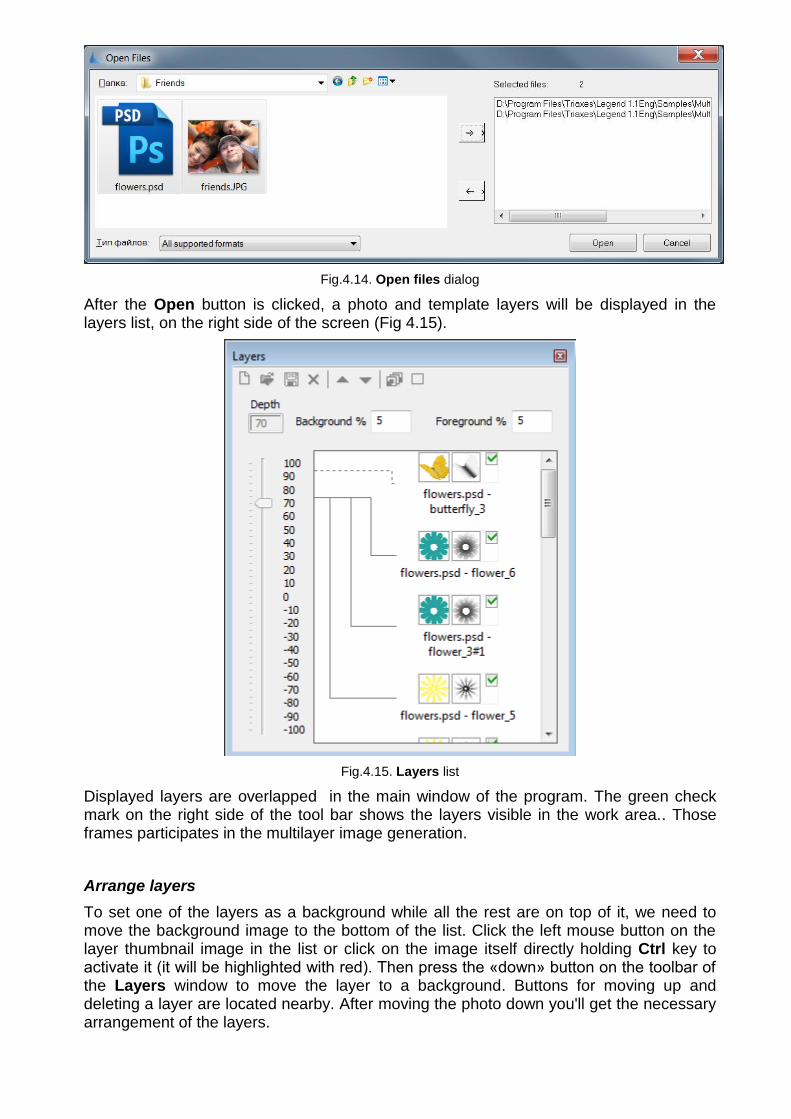
Fig.4.14. Open files dialog
After the Open button is clicked, a photo and template layers will be displayed in the layers list, on the right side of the screen (Fig 4.15).
Fig.4.15. Layers list
Displayed layers are overlapped in the main window of the program. The green check mark on the right side of the tool bar shows the layers visible in the work area.. Those frames participates in the multilayer image generation.
Arrange layers
To set one of the layers as a background while all the rest are on top of it, we need to move the background image to the bottom of the list. Click the left mouse button on the layer thumbnail image in the list or click on the image itself directly holding Ctrl key to activate it (it will be highlighted with red). Then press the «down» button on the toolbar of the Layers window to move the layer to a background. Buttons for moving up and deleting a layer are located nearby. After moving the photo down you'll get the necessary arrangement of the layers.

Fig.4.16. Photo is smaller than a template
Adjust image size and position
If a photo is a little bit smaller or bigger than a template, it is necessary to adjust its size to fit the template. Select Edit >> Transform >> Scale (hot keys Alt+S). The running frame (marching ants) will appear around the selected image.. Press the left mouse button and holding it, adjust new proportions of the image being scaled. Release the left mouse button only when it fits the template. Scaling is done in relation to the center of an image. You can repeat it till get the perfect result.
You can move the layer with the photo closer to the center of the template. Switch to the movement mode by clicking the right mouse button at any place on the screen. Click the photo with the left mouse button and drag it to the desired place, release the button when done. You can change the location of any layer in the same way. Just select it in the list and move to a desired position.
Working with lists in Triaxes Legend is similar to working with Windows lists: you can select a group of objects holding Shift key, or separate objects by pressing Ctrl. To make all layers invisible it is necessary to select an extreme layer Press Shift and click the check mark to the right of the layer located on the other side of the list.
Edit >> Transform >> Rotate (hot keys Alt+R) allows rotation at user-specified angle.
Repetitive use of scale and rotation operations in Triaxes Legend does not cause the loss of image quality. At any stage of editing it is possible to undo or redo the recent actions.
To save the result go to Project >> Save project from a menu or press Ctrl+S.
To exit the scaling and rotation mode press Esc key or click the right mouse button.
Adjust 3D (stereo) effect
To maintain an amazing 3D depth effect set parallaxes values for foreground and background in the respective fields – Foreground parallax and Background parallax. Then allocate layers in depth in relation to each other. To do so select a layer from the list and move up or down the depth scale slider.

Note: the optimal values of foreground and background parallaxes are defined by experiment. In this project as an example we set the value to 5, while you may try other values. In our opinion, the best result is achieved with parallax values of 5 to 9.
When we have correctly allocated layers on the canvas and set a relative depth, it is possible to add the depth map for each layer. Right click on the thumbnail image of the layer and select Load depth map.
Fig.4.17 Load depth map
A depth map can also be added when preparing a template in graphical editors. In this case a depth map will be stored as a separate layer directly in a template. When you open the depth map in Triaxes Legend it is necessary to specify the layer it corresponds to. To do so locate the depth map layer below the image layer in the list. Then right click on the original layer thumbnail image and select Attach bottom layer as depth map.
As a result, a depth map a thumbnail has to appear to the right of an image icon.

Fig.4.18.List of layers with depth maps
Generate multilayer 3D (stereo) image
The preparation stage is completed. Now it’s time to turn to the frame sequence generation process. Select Layers >> Generate multilayer stereo (hot keys: Alt+G). The Generate multilayer stereo dialog appears (Fig.4.19).
Fig.4.19. Generate multilayer stereo dialog
Depending on the specified parallax, the line in the list will be colored with blue or yellow. Yellow means, that the layer will be “elevated” from the medium plane, blue - that the layer will be depressed. The further away the layer moves from the medium plane the more saturated the color of the list line will become.
In Generate multilayer stereo dialog we set the number of frames to be generated and press Generate.
If for whatever reason you are not satisfied with the generated frames series (e.g. there was a mistake in parameters), it is possible to undo generation by pressing Ctrl+Z, choosing Edit >> Undo menu command, or selecting the respective frames and pressing Delete key.

Fig.4.20. Generated frames sequence
Multilayer 3D (stereo) image preview and export
To evaluate the stereo effect quickly you may switch to anaglyph mode and use colored glasses (Fig.4.21).
Fig.4.21. Anaglyph view mode for frame series
You can save the generated sequence of frames on disc, with the Project >> Export frames menu command.
Generated frames are modeling a multiview stereo photography. The frames are already aligned to each other, so you can switch directly to Frames tab, encode the image and start printing (see section 4.3 for more information).

4.3 Principles of direct printing on the lens
Most plotters for direct printing have special printing software for printing process control. Triaxes Legend is intended to generate the encoded image for viewing via lenticular lens. If you’re not going to mirror the image with special printing software, don’t forget to mark it with a tick Mirroring before encoding. To create a file with the encoded image use encoding To file.
Fig.4.22. Encoding to file option
Before printing it’s necessary to position the lens properly on the printing table in order to match the lens and the encoded bands.
To do so generate the positioning frame and print it on the printing table (fig. 4.23).
Fig.4.23. Calling of Positioning frame dialog
Fig.4.24. Positioning frame dialog
Adjust the appearance of the frame in Appearance settings block. It’s possible to add/remove the borders (up and down, on each side and on center). Use left mouse button.
It’s necessary to specify the precise lens pitch, therefore make a pitch test before.
Select the color of frame borders (black or white) for printing on white and black printing tables correspondingly.
The resolution parameter must be equal to the resolution of printing device.

It’s possible to Generate the frame to display and To file. Generate it to file if your plotter has special printing software.
It’s important to match the frame and the encoded image origin of coordinates.
Figure 4.25 shows the example of positioning frame printing using Mimaki A3.
Fig.4.25. Positioning frame printing on Mimaki A3 printing table
Then it’s necessary to position the lenticular lens in such a manner as to be able to see all lines without zigzags. To see the lines more clearly you can use additional devices such as lantern or magnifier (fig.4.36).

Fig.4.26. Positioning of lenticular lens on a plotter printing table
After positioning it’s necessary to switch on a vacuum pump to fix the lens and start printing.