lecture 2 single phase flow concepts. wellbore performance wellbore performance analysis involves...
TRANSCRIPT
Lecture 2Single Phase Flow Concepts

Wellbore Performance• Wellbore performance analysis involves
establishing a relationship between – tubular size
– wellhead and bottom-hole pressure
– fluid properties
– fluid production rate

Single-Phase Liquid Flow
• Single-phase liquid flow exists in an oil well only when the wellhead pressure is above the bubble-point pressure of the oil, which is usually not a reality.
• This is just a start point.
• Multiphase flow usually dominates.

Conservation of Momentum
• The rate of momentum out, minus the rate of momentum in, plus the rate of momentum accumulation in a given pipe segment must equal the sum of all forces on the fluids.
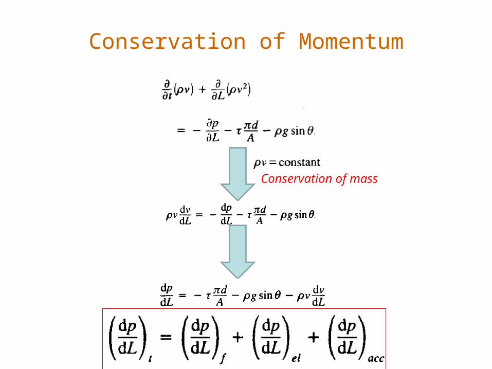
Conservation of Momentum
Conservation of mass

Flow to the Surface - Liquids• Taken as a macroscopic balance the changes at two
selected points can be examined
point 1
point 2

Conservation of Momentum
l
pp 12

Flow to the Surface - Liquids
• Flow of slightly compressible liquids is described by the steady state mechanical energy balance
• Steady state means that no properties are changing with time.
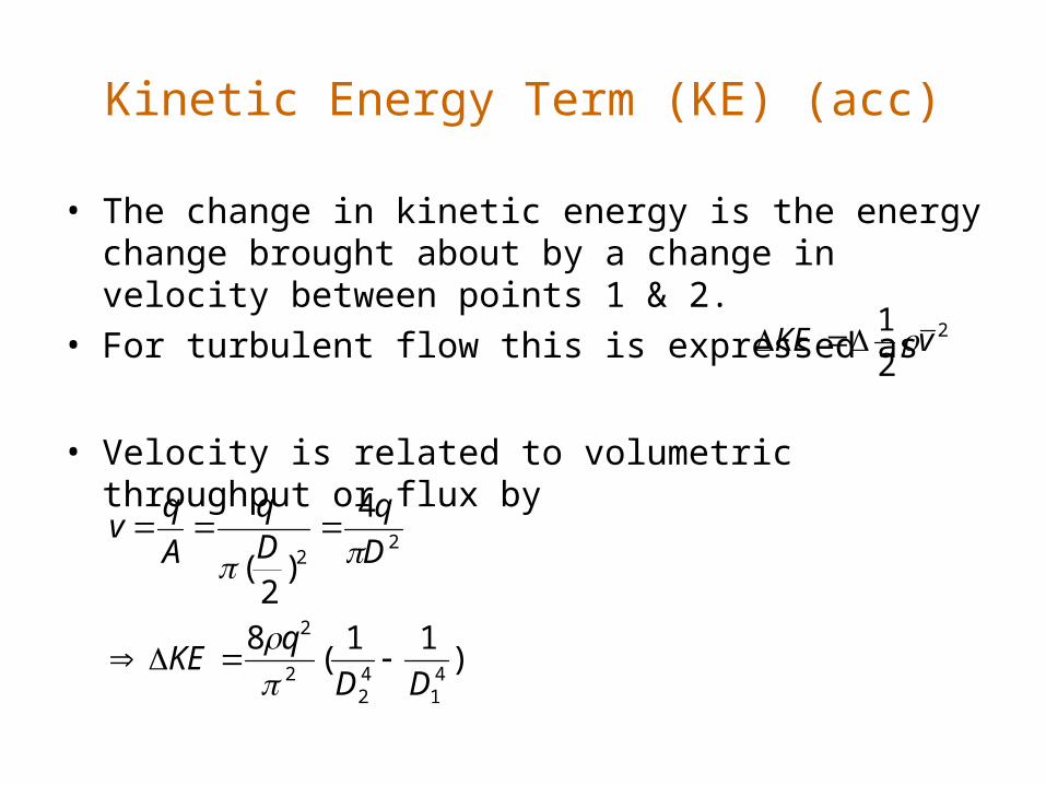
Kinetic Energy Term (KE) (acc)
• The change in kinetic energy is the energy change brought about by a change in velocity between points 1 & 2.
• For turbulent flow this is expressed as
• Velocity is related to volumetric throughput or flux by
2
2
1vKE
)11
(8
4
)2
(
41
42
2
2
22
DD
qKE
D
qDq
A
qv

Potential Energy Term (PE) (el)
• The change in potential energy is the change brought about by elevation change between point 1 & 2.
• The flow may be inclined at an angle, or be horizontal.
sinLgPE

Friction
• Frictional energy loss is a function of velocity, viscosity, density, pipe size, & condition.
• Correlations developed by Moody are widely used to obtain a Fanning friction factor based on Reynolds Number
f
D
LvEv
4
2
1 2
vD
N ReMoody friction factor
4
'4
2
1 2 f
D
LvEv
Fanning friction factor

Moody Friction Factor

Moody Friction Factor

Pipe Roughness

Fanning Friction Factor
• Many correlations exist. A good one is presented by Chen
roughness. pipe is andNumber Reynolds is Re where
))R
149.7(
8257.2log
R
0452.5
7065.3log(4
1 8981.
e
1098.1
e
f
Fanning friction factor = (1/4) Moody friction factor

Friction in Fittings
• Friction loss in fittings is negligible in flow though long lines. However it may be important in short distance applications. If so it is added to the friction term as
fittinggiven afor factor loss theis e where
2
1
v
2
ivf evFR

Friction in Fittings
0.2 valvegate
10-6 valveglobe
0.4-0.3 elbow deg 45
1.9-1.3 (square) elbow deg 90
0.9-0.4 (rounded) elbow deg 90
area sectional crosslarger
area sectional crosssmaller where
1)-)(1-2.7(1 orifice edged sharp
11
expansion sudden
)-0.45(1 n contractiosudden
0.05 pipe a toentrance rounded
belowgiven fittings for thefactor loss theis e
22
2
v
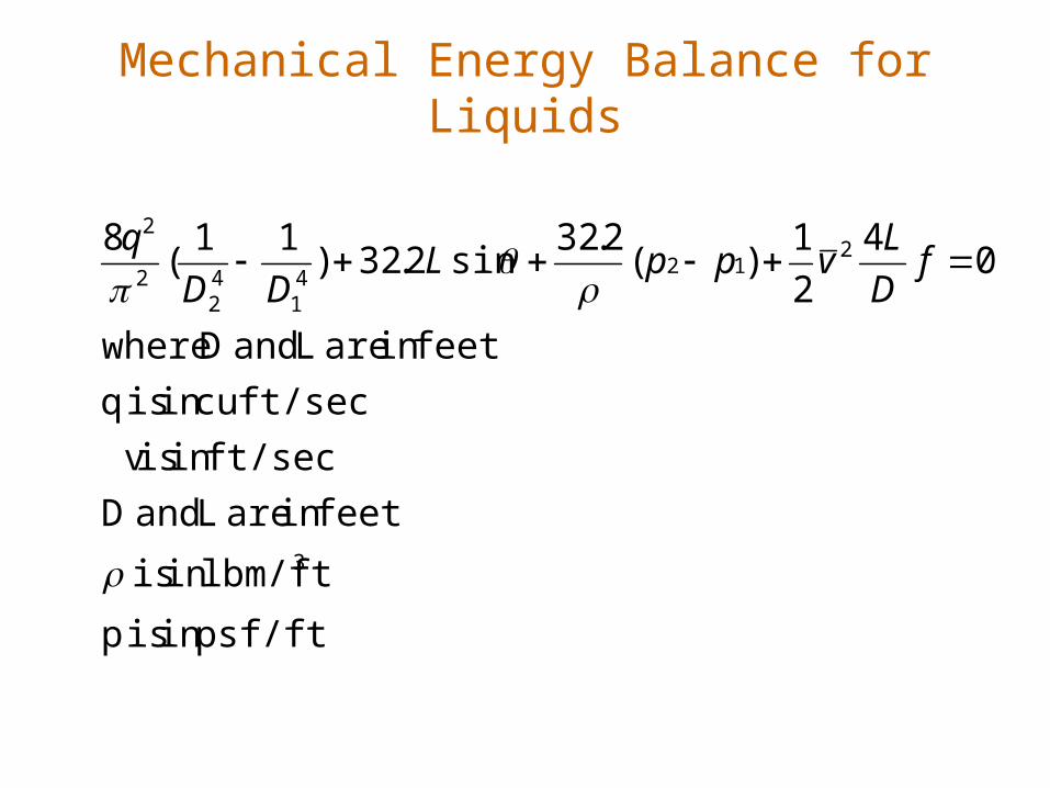
Mechanical Energy Balance for Liquids
psf/ftin is p
lbm/ftin is
feetin are L and D
ft/secin is v
ft/seccu in is q
feetin are L and D where
04
2
1)(
2.32sin2.32)
11(
8
3
212
41
42
2
2
f
D
LvppL
DD
q

Example 1
• Calculate the pressure change in a water injection well. The following data are known.
Example 2
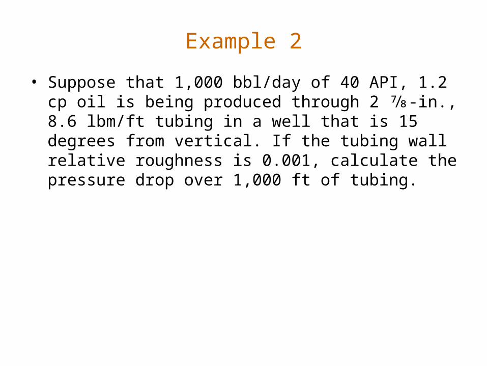
• Suppose that 1,000 bbl/day of 40 API, 1.2 cp oil is being produced through 2 7⁄8-in., 8.6 lbm/ft tubing in a well that is 15 degrees from vertical. If the tubing wall relative roughness is 0.001, calculate the pressure drop over 1,000 ft of tubing.

Liquid Pressure Traverse
• A pressure traverse is a plot of the flowing pressure versus position in the pipe.
• For the case of a slightly compressible liquid the plot is a straight line from P1 to P2 across L1 to L2.
• You can verify this result by breaking the flow length into increments and computing and plotting the end point of each increment.
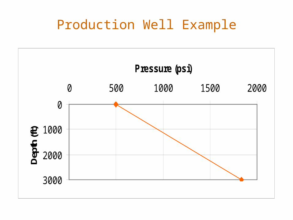
Production Well Example
0
1000
2000
3000
0 500 1000 1500 2000
Pressure (psi)
Dep
th (f
t)

Single-Phase Gas Flow
• The first law of thermodynamics (conservation of energy) governs gas flow in tubing. The effect of kinetic energy change is negligible because the variation in tubing diameter is insignificant in most gas wells. With no shaft work device installed along the tubing string, the first law of thermodynamics yields the following mechanical balance equation:

Single-Phase Gas Flow
• Since dz is Sin(θ).dL
• The gas density from the gas law can be expressed as
• The velocity can be written in terms of volumetric flow rate at the standard condition as

Main Equation for Gas Flow in Wellbores

Solution
• This equation contains Three variables that are functions of position
• Z (compressibility factor)
• Temperature
• Pressure
• A simple approach is to use average values of temperature and Z over a segment of the pipe.
• There are two options for temperature in a segment between points 1 and 2

Method to Calculate P in a Segment
• T_average can be obtained from T1 and T2
• Z_average is calculated from T_average and P1
• In the segment, we can calculate P2• Z_average can be updated with new
P in the segment which is (P1+P2)/2• We repeat the calculate until
convergence.
P1, T1
P2, T2
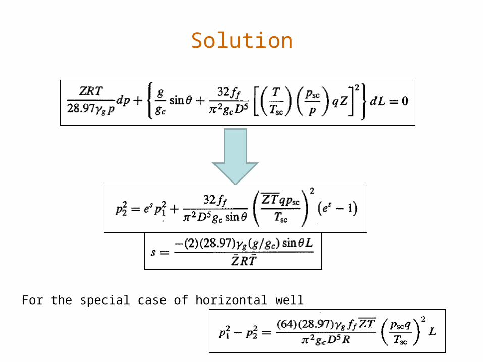
Solution
For the special case of horizontal well

Oil Field Unit
P1
P2
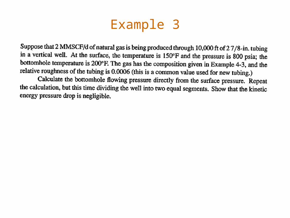
Example 3