laboratory test procedure for safety/test procedures... · tp111sb-00 december 30, 1999 u.s....
TRANSCRIPT
TP111SB-00 December 30, 1999
U.S. DEPARTMENT OF TRANSPORTATION
NATIONAL HIGHWAY TRAFFIC SAFETY ADMINISTRATION
LABORATORY TEST PROCEDURE
FOR
FMVSS – School Bus Rearview Mirrors
SAFETY ASSURANCE Office of Vehicle Safety Compliance
Room 6111, NSA-30 400 Seventh Street, SW Washington, DC 20590

OVSC LABORATORY TEST PROCEDURE NO. 111SB TABLE OF CONTENTS
PAGE 1. PURPOSE AND APPLICATION................................................................... 1
2. GENERAL REQUIREMENTS....................................................................... 2
3. SECURITY ................................................................................................... 3
4. GOOD HOUSEKEEPING............................................................................. 4
5. TEST SCHEDULING AND MONITORING ................................................... 4
6. TEST DATA DISPOSITION.......................................................................... 4
7. GOVERNMENT FURNISHED PROPERTY (GFP)....................................... 5
8. CALIBRATION OF TEST INSTRUMENTS................................................... 6
9. PHOTOGRAPHIC DOCUMENTATION........................................................ 7
10. DEFINITIONS............................................................................................... 8
11. PRETEST REQUIREMENTS ....................................................................... 9
12. COMPLIANCE TEST EXECUTION.............................................................. 11
13. POST TEST REQUIREMENTS.................................................................... 23
14. REPORTS .................................................................................................... 23
14.1. MONTHLY STATUS REPORTS....................................................... 23 14.2. APPARENT TEST FAILURE ............................................................ 23 14.3. FINAL TEST REPORTS ................................................................... 24
14.3.1.COPIES ................................................................................. 24 14.3.2.REQUIREMENTS.................................................................. 24 14.3.3.FIRST THREE PAGES.......................................................... 25 14.3.4.TABLE OF CONTENTS......................................................... 31
15. DATA SHEETS............................................................................................. 32
16. FORMS ........................................................................................................ 47
APPENDIX 1 ................................................................................................ 50 APPENDIX 2 ................................................................................................ 55
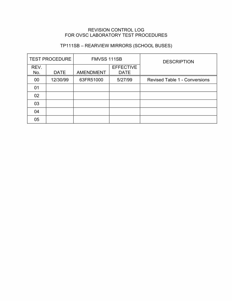
REVISION CONTROL LOG FOR OVSC LABORATORY TEST PROCEDURES
TP111SB – REARVIEW MIRRORS (SCHOOL BUSES)
TEST PROCEDURE FMVSS 111SB DESCRIPTION REV. No. DATE AMENDMENT
EFFECTIVE DATE
00 12/30/99 63FR51000 5/27/99 Revised Table 1 - Conversions
01
02
03
04
05
1
1. PURPOSE AND APPLICATION
The Office of Vehicle Safety Compliance (OVSC) provides contractor laboratories with Laboratory Test Procedures as guidelines for obtaining compliance test data. The data are used to determine if a specific vehicle or item of motor vehicle equipment meets the minimum performance requirements of the subject Federal Motor Vehicle Safety Standard (FMVSS). The purpose of the OVSC Laboratory Test Procedures is to present a uniform testing and data recording format, and provide suggestions for the use of specific equipment and procedures. If any contractor views any part of an OVSC Laboratory Test Procedure to be in conflict with a Federal Motor Vehicle Safety Standard (FMVSS) or observes deficiencies in a Laboratory Test Procedure, the contractor is required to advise the Contracting Officer's Technical Representative (COTR) and resolve the discrepancy prior to the start of compliance testing.
Every contractor is required to submit a detailed test procedure to the COTR before initiating the compliance test program. The procedure must include a step-by-step description of the methodology to be used. The contractor’s test procedure shall contain a complete listing of test equipment with make and model number and a detailed check-off sheet. The list of test equipment shall include instrument accuracy and calibration dates. All equipment shall be calibrated in accordance with the manufacturer’s instructions. There shall be no contradictions between the Laboratory Test Procedure and the contractor’s in-house test procedure. Written approval of the in-house test procedures shall be obtained from the COTR before initiating the compliance test program. The OVSC Laboratory Test Procedures are not intended to limit or restrain a contractor from developing or utilizing any testing techniques or equipment which will assist in procuring the required compliance test data. These Laboratory Test Procedures do not constitute an endorsement or recommendation for use of any product or method. However, the application of any such testing technique or equipment is subject to prior approval of the COTR.
NOTE: The OVSC Laboratory Test Procedures, prepared for the limited purpose of use by independent laboratories under contract to conduct compliance tests for the OVSC, are not rules, regulations or NHTSA interpretations regarding the meaning of a FMVSS. The Laboratory Test Procedures are not intended to limit the requirements of the applicable FMVSS(s). In some cases, the OVSC Laboratory Test Procedures do not include all of the various FMVSS minimum performance requirements. Recognizing applicable test tolerances, the Laboratory Test Procedures may specify test conditions that are less severe than the minimum requirements of

2
1. PURPOSE AND APPLICATION....Continued
the standard. In addition, the Laboratory Test Procedures may be modified by the OVSC at any time without notice, and the COTR may direct or authorize contractors to deviate from these procedures, as long as the tests are performed in a manner consistent with the standard itself and within the scope of the contract. Laboratory Test Procedures may not be relied upon to create any right or benefit in any person. Therefore, compliance of a vehicle or item of motor vehicle equipment is not necessarily guaranteed if the manufacturer limits its certification tests to those described in the OVSC Laboratory Test Procedures.
2. GENERAL REQUIREMENTS
FMVSS 111 specifies requirements for the performance and location of rearview mirrors.
REQUIREMENTS FOR SCHOOL BUSES
Each school bus shall have two outside rearview mirror systems: System A and System B. System A shall be located with stable supports so that the portion of the system on the bus's left side, and the portion on its right side, each include at least one mirror of unit magnification with not less than 323 square cm (50 square inches) of reflective surface, and meet the specified field-of-view requirements. System B mirrors cover areas in front of the school bus, along the front sides and further back to augment System A mirrors.
REQUIREMENTS FOR VEHICLES OTHER THAN SCHOOL BUSES
Refer to the latest revision of TP-111V for testing of mirror systems other than school buses.
3
2. GENERAL REQUIREMENTS....Continued
TEST DATA LOSS
A compliance test is not to be conducted unless all of the various test conditions specified in the applicable OVSC Laboratory Test Procedure have been met. Failure of a contractor to obtain the required test data and to maintain acceptable limits on test parameters in the manner outlined in the applicable OVSC Laboratory Test Procedure may require a retest at the expense of the contractor. The retest costs will include the cost of leasing a replacement school bus and all costs associated with conducting the retest. The original test specimen (vehicle or equipment item) used for the invalid test shall remain the property of OVSC, and the retest specimen shall remain the property of the contractor. If there is a test failure, the contractor shall retain the retest specimen for a period not exceeding 180 days. If there is no test failure, the Contractor may dispose of the test specimen upon notification from the COTR that the final test report has been accepted.
The Contracting Officer of NHTSA is the only NHTSA official authorized to notify the contractor that a retest is required. The retest shall be completed within two (2) weeks after receipt of notification by the Contracting Officer that a retest is required. If a retest is conducted, no test report is required for the original test.
3. SECURITY
The contractor shall provide appropriate security measures to protect the OVSC test vehicles from unauthorized personnel during the entire compliance testing program. The contractor is financially responsible for any acts of theft and/or vandalism which occur during the storage of test vehicles. Any security problems which arise shall be reported by telephone to the Industrial Property Manager (IPM), Office of Contracts and Procurement, within two working days after the incident. A letter containing specific details of the security problem will be sent to the IPM (with copy to the COTR) within 48 hours. The contractor shall protect and segregate the data that evolves from compliance testing before and after each vehicle test. No information concerning the vehicle safety compliance testing program, shall be released to anyone except the COTR, unless specifically authorized by the COTR or the COTR's Branch Chief or Division Chief.
NOTE: NO INDIVIDUALS, OTHER THAN CONTRACTOR PERSONNEL DIRECTLY INVOLVED IN THE COMPLIANCE TESTING PROGRAM OR OVSC PERSONNEL, SHALL BE ALLOWED TO WITNESS ANY VEHICLE COMPLIANCE TEST UNLESS SPECIFICALLY AUTHORIZED BY THE COTR.
4
4. GOOD HOUSEKEEPING
Contractors shall maintain the entire vehicle compliance testing area, test fixtures and instrumentation in a neat, clean and painted condition with test instruments arranged in an orderly manner consistent with good test laboratory housekeeping practices.
5. TEST SCHEDULING AND MONITORING
The contractor shall submit a vehicle test schedule to the COTR prior to conducting the first compliance test. Tests shall be completed as required in the contract.
Scheduling of vehicle tests shall be adjusted to permit vehicles to be tested to other FMVSSs as may be required by the OVSC. All vehicle compliance testing shall be coordinated with the COTR in order to allow monitoring by the COTR and/or other OVSC personnel if desired.
6. TEST DATA DISPOSITION
The contractor shall make all vehicle preliminary compliance test data available to the COTR at the test site within four hours after the test. Final test data, including digital printouts and computer generated plots (if applicable), shall be furnished to the COTR within five working days. Additionally, the contractor shall analyze the preliminary test results as directed by the COTR.
All backup data sheets, strip charts, recordings, plots, technician's notes, etc., shall be either sent to the COTR or destroyed at the conclusion of each delivery order, purchase order, etc.
5
7. GOVERNMENT FURNISHED PROPERTY (GFP)
ACCEPTANCE OF TEST VEHICLES
The Contractor has the responsibility of accepting each GFP test vehicle whether delivered by a new vehicle dealership or another vehicle transporter. In both instances, the contractor acts in the OVSC's behalf when signing an acceptance of the GFP test vehicle delivery. When a new GFP vehicle is delivered, the contractor must check to verify the following:
A. All options listed on the "window sticker" are present.
B. Tires and wheel rims are new and the same as listed.
C. There are no dents or other interior or exterior flaws.
D. The vehicle has been properly prepared and is in running condition.
E. Owner's Manual, warranty document, consumer information, and extra set of keys are present, and
F. Proper fuel filler cap is supplied on the vehicle.
In addition, if the test vehicle is delivered by a government contracted transporter, the contractor shall check for damage which may have occurred during transit.
A “Vehicle Condition” form will be supplied to the contractor by the COTR when the test vehicle is transferred from the new car dealer or between test contracts. The upper half of the form describes the vehicle condition prior to test in detail, and the lower half provides space for a description of the post-test condition. The Vehicle Condition form must be completed and delivered to the COTR with the Final Test Report or the report will NOT be accepted.
NOTIFICATION OF COTR
The COTR must be notified within 24 hours after a vehicle has been delivered. In addition, if any discrepancy or damage is found at the time of delivery, a copy of the Vehicle Condition form shall be sent to the COTR immediately.
6
8. CALIBRATION OF TEST INSTRUMENTS
Before the contractor initiates the safety compliance test program, a test instrumentation calibration system shall be implemented and maintained in accordance with established calibration practices. The calibration system shall include the following as a minimum:
A. Standards for calibrating the measuring and test equipment will be stored and used under appropriate environmental conditions to assure their accuracy and stability.
B. All measuring instruments and standards shall be calibrated by the contractor, or a commercial facility, against a higher order standard at periodic intervals NOT TO EXCEED TWELVE (12) MONTHS! Records, showing the calibration traceability to the National Institute of Standards and Technology (NIST), shall be maintained for all measuring and test equipment.
C. All measuring and test equipment and measuring standards will be labeled with the following information:
(1) Date of calibration
(2) Date of next scheduled calibration
(3) Name of the technician who calibrated the equipment
D. A written calibration procedure shall be provided by the contractor which includes as a minimum the following information for all measurement and test equipment:
(1) Type of equipment, manufacturer, model number, etc.
(2) Measurement range
(3) Accuracy
(4) Calibration interval
(5) Type of standard used to calibrate the equipment (calibration traceability of the standard must be evident)
7
8. CALIBRATION OF TEST INSTRUMENTS....Continued
E. Records of calibration for all test instrumentation shall be kept by the contractor in a manner which assures the maintenance of established calibration schedules. All such records shall be readily available for inspection when requested by the COTR. The calibration system will need the acceptance of the COTR before the test program commences.
Further guidance is provided in the International Standard ISO 10012-1, “Quality Assurance Requirements for Measuring Equipment” and American National Standard ANSI/NCSL Z540-1, “Calibration Laboratories and Measuring and Test Equipment - General Requirements”.
9. PHOTOGRAPHIC DOCUMENTATION
Photographs shall be 8 x 10 inches (black and white or color), and properly focused for clear images. A label or placard identifying the test vehicle model, NHTSA number and date (or item of equipment part number and date) shall appear in each photograph and must be legible. Each photograph shall be labeled as to the subject matter.
As a minimum the following photographs shall be included in each final test report, where applicable:
A. 3/4 frontal view from left side of vehicle
B. 3/4 rear view from right side of vehicle
C. Closeup view of vehicle's certification label
D. Closeup view of incomplete vehicle manufacturer’s certification label.
E. Closeup view of vehicle's tire information placard or label
F. All rearview mirrors and mirror mountings
G. Field-of-view test setups, including viewing instrument
H. Reflectance test setup
I. Photos required to document test results

8
9. PHOTOGRAPHIC DOCUMENTATION....Continued
J. Photos of test cylinders
K. Photos to document any apparent test failure
10. DEFINITIONS
CONVEX MIRROR
Mirror having a curved reflective surface whose shape is the same as that of the exterior surface of a section of a sphere.
EFFECTIVE MIRROR SURFACE
The portions of a mirror that reflect images, excluding the mirror rim or mounting brackets.
PLAN VIEW REFERENCE LINE
For vehicles with bench-type seats, a line parallel to the vehicle longitudinal centerline located outboard of the steering wheel centerline at a distance 0.15 times the difference between one-half of the shoulder room dimension and the steering wheel centerline-to-bus-centerline dimension.
For vehicles with individual-type seats, a line parallel to the vehicle longitudinal centerline which passes through the center of the driver's designated seating position.
PROJECTED EYE POINT
Point on a horizontal plane forward of the mirror at a distance equal to the true distance from the eye to the mirror.
SEATING REFERENCE POINT (SRP)
Vehicle manufacturer's design H-point with the seat in the rearmost driving position, which for purposes of this procedure simulates the position of the pivot center of the human torso and thigh.
9
10. DEFINITIONS....Continued
STANDARD PRODUCTION ITEMS
Items installed during the assembly of the test vehicle.
UNIT MAGNIFICATION MIRROR
Plane or flat mirror with a reflective surface through which the angular height and width of the image of an object is equal to the angular height and width of the object when viewed directly at the same distance, except for flaws that do not exceed normal manufacturing tolerances. For the purposes of this regulation a prismatic day night adjustment rearview mirror, one of whose positions provides unit magnification, is considered a unit magnification mirror.
11. PRETEST REQUIREMENTS
Prior to conducting a compliance test, the contractor shall:
A. Verify COTR approval of contractor’s In-house Test Procedure,
B. Verify the training of technicians for performance of this test,
C. Verify the calibration status of test equipment,
D. Review applicable revision of FMVSS 111
E. Review vehicle Owner’s Manual
TEST AREA
The compliance test area must be level and sufficiently sized to position test cylinders at the correct locations as described in Section 12.B.6 of this procedure. The test area floor should be grid-marked to aid in locating the test vehicles and cylinders. Unless specified otherwise, all tests shall be performed within a temperature range of 26.7�C (80�F) plus or minus 6.6�C (20�F) and a relative humidity of not more than 90 percent.

10
11. PRETEST REQUIREMENTS....Continued
TEST EQUIPMENT
The laboratory shall provide a 35 mm or larger format camera for documentary photographs (S13.6).
The laboratory shall provide test cylinders A through P as identified in Figure 1. Test cylinders color contrasts with the test area and have the following dimension: 0.3048 meters (1 foot) in height and 0.3048 meters (1 foot) in diameter, except test cylinder P which has the same diameter as test cylinders A through O but has a height of 0.9114 meters (3 feet).
VEHICLE PREPARATION
A. Clean all mirrors and both sides of all glazing involved in the compliance test with a non-abrasive cleaner.
B. The fuel tank shall be full.
C. All tire pressures shall be set cold according to the vehicle manufacturer's recommendation.
PERMANENT RECORDING OF DATA
Where permanent trace recording is not required, data shall be recorded on standard report forms. Changes or corrections shall be made by drawing a line through the original entry, which must remain legible, adding the change above or alongside, and initialed.
METRIC UNITS
As a general rule, use of the metric system of weights and measures is preferred. Performance parameters and test conditions in FMVSS 111 are now specified in metric units. In this Laboratory Test Procedure metric values are followed by English units only for reference (not necessarily equal). If test equipment is not available for direct measurement in metric units, the test laboratory shall calculate the exact metric equivalent by means of a conversion factor carried out to at least 5 significant digits before rounding consistent with the specified metric requirement. Metric units shall be used in Final Test Reports.
11
12. COMPLIANCE TEST EXECUTION
A. REQUIREMENTS
Each school bus shall be equipped with two outside review mirror systems: System A and System B (S9.1).
(1) System A (S9.2) shall be located with stable supports so that the portion of the system on the bus's left side, and the portion on its right side, each:
(A) Includes at least one mirror of unit magnification with not less than 323 square centimeters (50 square inches) of reflective surface; and
(B) Includes one or more mirrors which together provide, at the driver's eye location, a view of:
(1)
(2)
For the mirror system on the right side of the bus, the entire top surface of cylinder N in Figure 1, and that area of the ground extending rearward from cylinder N to a point not less than 61 meters (200 feet) from the mirror surface.
For the mirror system on the left side of the bus, the entire top surface of cylinder M in Figure 1, and that area of the ground extending rearward from cylinder M to a point not less than 61 meters (200 feet) from the mirror surface. (NOTE: Refer to Oct. 1, 1997 CFR. More current editions are not correct)
(2) System B (S9.3(a)) shall provide for EACH of the cylinders A through P in Figure 1 whose ENTIRE TOP SURFACE IS NOT DIRECTLY VISIBLE FROM THE DRIVER'S EYE LOCATION:
(A) A view of the entire top surface of that cylinder.
(B) A view of the ground that overlaps with the view of the ground provided by System A.
12
12. COMPLIANCE TEST EXECUTION....Continued
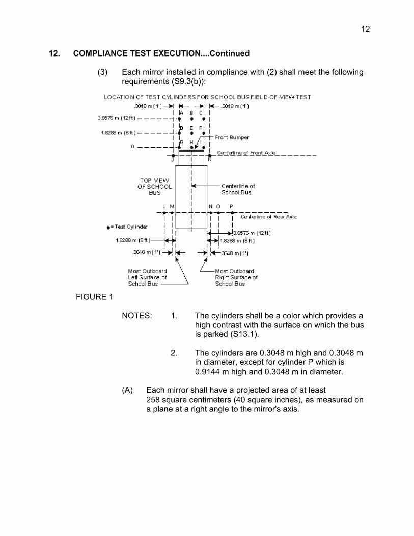
(3) Each mirror installed in compliance with (2) shall meet the following requirements (S9.3(b)):
FIGURE 1
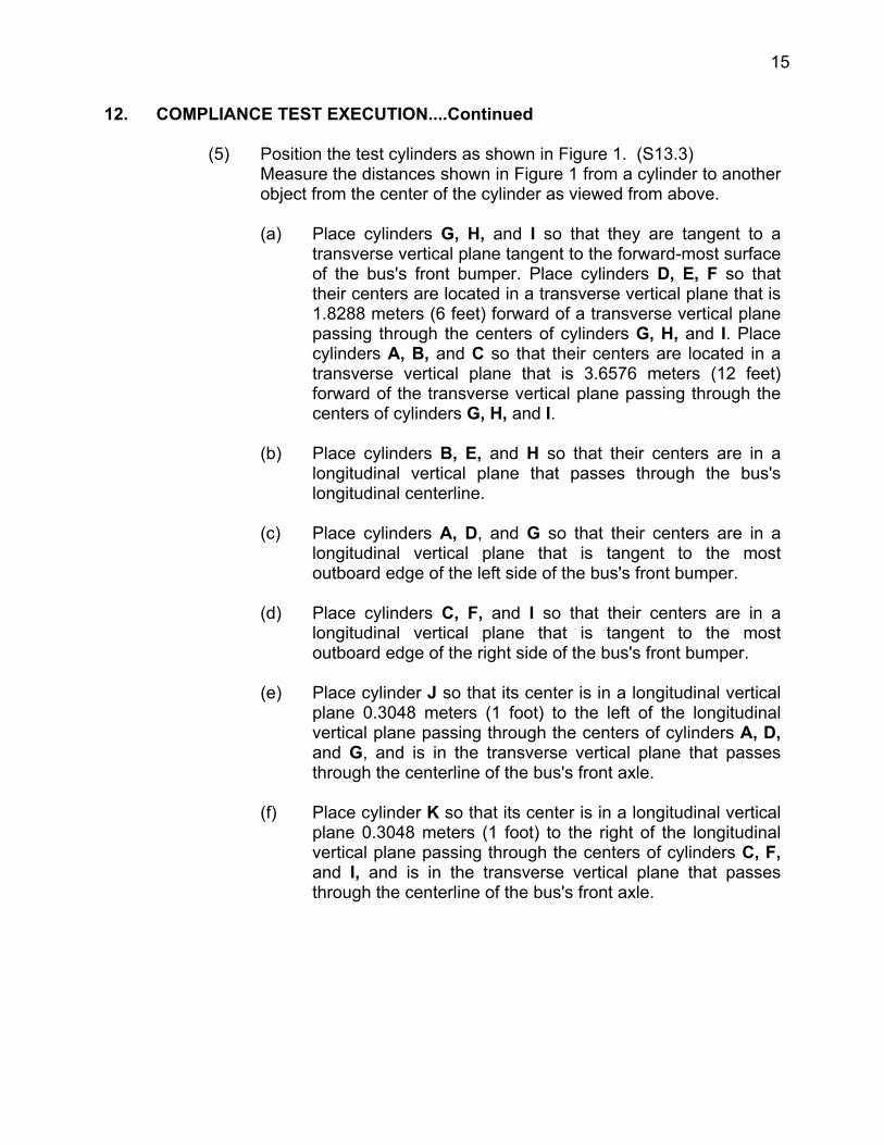
NOTES: 1. The cylinders shall be a color which provides a high contrast with the surface on which the bus is parked (S13.1).
2. The cylinders are 0.3048 m high and 0.3048 m in diameter, except for cylinder P which is 0.9144 m high and 0.3048 m in diameter.
(A) Each mirror shall have a projected area of at least 258 square centimeters (40 square inches), as measured on a plane at a right angle to the mirror's axis.

13
12. COMPLIANCE TEST EXECUTION....Continued
(B) Each mirror shall be located such that the distance from the center point of the eye location of a 25th percentile adult female seated in the driver's seat to the center of the mirror shall be at least 95 centimeters (37.5 inches).
(C) Each mirror shall have no discontinuities in the slope of the surface of the mirror.
(D) Each mirror system shall be installed with a stable support.
(4) Each school bus which has a mirror installed in compliance with (2) that has an average radius of curvature less than 889 mm, (35 inches), as determined under S12, shall have a label visible to the seated driver (S9.3(c)).
The label shall be printed in a type face and color that are clear and conspicuous, and state the following:
"USE CROSS VIEW MIRRORS TO VIEW PEDESTRIANS WHILE BUS IS STOPPED. DO NOT USE THESE MIRRORS TO VIEW TRAFFIC WHILE BUS IS MOVING. IMAGES IN SUCH MIRRORS DO NOT ACCURATELY SHOW ANOTHER VEHICLE'S LOCATION."
(5) Each image required by (2)(A) to be visible at the driver's eye location shall be separated from the edge of the effective mirror surface by a distance of not less than 3 minutes of arc (S9.4 (a)).
(6) The image required by (2)(A) of cylinder P shall meet the following requirements (S9.4(b)):
(A) The angular size of the shortest dimension of that cylinder's image shall be not less than 3 minutes of arc; and
(B) The angular size of the longest dimension of that cylinder's image shall be not less than 9 minutes of arc.
14
12. COMPLIANCE TEST EXECUTION....Continued
(7) Reflectance Test (S11)
All single reflectance mirrors shall have an average reflectance of at least 35 percent. If a mirror is capable of multiple reflectance levels, the minimum reflectance level in the day mode shall be at least 35 percent and the minimum reflectance level in the night mode shall be at least 4 percent. The average reflectance of any mirror required by this standard shall be determined in accordance with SAE Recommended Practice J964, OCT 84.
A multiple reflectance mirror shall either be equipped with a means for the driver to adjust the mirror to a reflectance level of at least 35 percent in the event of electrical failure, or achieve such reflectance level automatically in the event of electrical failure.
B. PROCEDURE
(1) Inspect the installation of the outside rearview mirrors. Note any evidence of defects or imperfections which could influence the test. Operate the outside rearview mirrors in all directions to verify that the devices meet the manufacturer’s specifications in the Vehicle Owner’s Manual.
Record the results on vehicle inspection and identification Data Sheet 1.
(2) Park the vehicle using stable supports to prevent movement on the test area. Clear the area 4.3 meters (14 feet) in front of the bus and 4 meters (13.2 feet) on each side of the bus for test cylinder positioning. Also, there should be a view of the ground not less than 61 meters (200 feet) from the rearmost mirror surfaces.
(3) Obtain from the COTR the manufacturer's recommended mirror adjustments and adjust the mirrors accordingly. Mirrors are not to be moved or readjusted at anytime during the test. (S13.5)
(4) All observations and photographs must be taken with the service/entry door in the closed position and the stop signal arm(s) in the fully retracted position. (S13.8)
15
12. COMPLIANCE TEST EXECUTION....Continued
(5) Position the test cylinders as shown in Figure 1. (S13.3) Measure the distances shown in Figure 1 from a cylinder to another object from the center of the cylinder as viewed from above.
(a) Place cylinders G, H, and I so that they are tangent to a transverse vertical plane tangent to the forward-most surface of the bus's front bumper. Place cylinders D, E, F so that their centers are located in a transverse vertical plane that is 1.8288 meters (6 feet) forward of a transverse vertical plane passing through the centers of cylinders G, H, and I. Place cylinders A, B, and C so that their centers are located in a transverse vertical plane that is 3.6576 meters (12 feet) forward of the transverse vertical plane passing through the centers of cylinders G, H, and I.
(b) Place cylinders B, E, and H so that their centers are in a longitudinal vertical plane that passes through the bus's longitudinal centerline.
(c) Place cylinders A, D, and G so that their centers are in a longitudinal vertical plane that is tangent to the most outboard edge of the left side of the bus's front bumper.
(d) Place cylinders C, F, and I so that their centers are in a longitudinal vertical plane that is tangent to the most outboard edge of the right side of the bus's front bumper.
(e) Place cylinder J so that its center is in a longitudinal vertical plane 0.3048 meters (1 foot) to the left of the longitudinal vertical plane passing through the centers of cylinders A, D, and G, and is in the transverse vertical plane that passes through the centerline of the bus's front axle.
(f) Place cylinder K so that its center is in a longitudinal vertical plane 0.3048 meters (1 foot) to the right of the longitudinal vertical plane passing through the centers of cylinders C, F, and I, and is in the transverse vertical plane that passes through the centerline of the bus's front axle.
16
12. COMPLIANCE TEST EXECUTION....Continued
(g) Place cylinders L, M, N, O, and P so that their centers are in the transverse vertical plane that passes through the centerline of the bus's rear axle. Place cylinder L so that its center is in a longitudinal vertical plane that is 1.8288 meters (6 feet) to the left of the longitudinal vertical plane tangent to the bus's most outboard left surface (excluding the mirror system). Place cylinder M so that its center is in a longitudinal vertical plane that is 0.3048 meters (1 foot) to the left of the longitudinal vertical plane tangent to the left side of the bus. Place cylinder N so that its center is in a longitudinal vertical plane that is 0.3048 meters (1 foot) to the right of the longitudinal vertical plane tangent to the right side of the bus. Place cylinder O so that its center is in a longitudinal vertical plane that is 1.8288 meters (6 feet) to the right of the longitudinal vertical plane tangent to the right side of the bus. Place cylinder P so that its center is in a longitudinal vertical plane that is 3.6576 meters (12 feet) to the right of the longitudinal vertical plane tangent to the right side of the bus.
(6) Place a marker/indicator such as a safety cone, flag, or cylinder on the test area floor 61meters (200 feet) behind the System A mirror used to view test cylinder N (right side of bus).
(7) Place a marker/indicator such as a safety cone, flag, or cylinder on the test area floor 61meters (200 feet) behind the System A mirror used to view test cylinder M (left side of bus).
(8) Obtain from the COTR the position of the driver's eye location and the seat back adjustment for the tests.
(9) The position of the driver's eye location is that of a 25th percentile adult female, when seated in the driver's seat as follows (S13.4):
(a) Adjust the driver's seat to the midway point between the forwardmost and rearmost positions, and if separately adjustable in the vertical direction, adjust to the lowest position. If adjustment position does not exist at the midway point, use the closest adjustment position to the rear of the midpoint. If seat back is adjustable, adjust the seat back angle to the manufacturer's nominal design riding position in accordance with the manufacturer's recommendations.
17
12. COMPLIANCE TEST EXECUTION....Continued
(b) The CENTER POINT of the driver's eye location is the point located 68.58 centimeters (27 inches) vertically above the intersection of the seat cushion and the seat back at the longitudinal centerline of the seat.
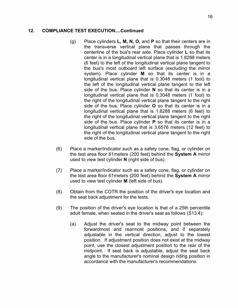
(10) Place a 35 mm or larger format camera so that its image plane is located at the CENTER POINT of the driver's eye location or at any single point within a semicircular area established by a 15.24 centimeter (6 inch) radius measured from the CENTER POINT and perpendicular to the vehicle longitudinal centerline and forward of the CENTER POINT (see Figure 2). (S13.6)
CAMERA LOCATIONS FOR SCHOOL BUS FIELD-OF-VIEW TEST
DRIVER'S EYE
15.24 cm (6 15.24 cm (6
FIGURE 2
NOTE: All photographs shall be taken at a single point within the above prescribed area. Label all photographs with the NHTSA number, mirror number, vehicle make and model, dates photographs were taken, and identification and location of test cylinders.
18
12. COMPLIANCE TEST EXECUTION....Continued
NOTE: Photographs of test cylinders should be made with the ENTIRE TOP SURFACE of the cylinder visible. If the entire top surface cannot be observed, then the cylinder is classified as not visible.
(11) Photograph using NO mirror system, as many of the cylinders A through P as possible trying to include in the photograph the entire top surface of each cylinder.
(12) Determine which cylinders, A through P, do NOT have their entire top surface directly visible by inspecting the photographs from the previous item. Cylinders not visible in their entirety must be visible in the System B mirror system as described below. Record the results on Data Sheet 2.
(13) Determine the mirrors which belong to System A and System B as described in requirements section 12A. (Mirror System A consists, in part, of at least one mirror of unit magnification on both sides of the bus. System B mirrors provide a view of each cylinder not directly visible from the driver’s eye location). Make a diagram of mirror locations on the bus similar to sample diagram given on Data Sheet 2. Insert diagram on Data Sheet 2.
(14) Photograph using mirror System A, the top surface of cylinder N and the rearward 61 meters (200 feet) indicator placed in item (7). Verify that the ENTIRE top surface is visible. Record the results on Data Sheet 2. (S9.2(b)(1))
(15) Photograph using mirror System A, the top surface of cylinder M and the rearward 61 meters (200 feet) indicator placed in item (8). Verify that the ENTIRE top surface is visible. Record the results on Data Sheet 2. (S9.2(b)(2)) (NOTE: Refer to Oct. 1, 1997 CFR. More current editions are not correct)
19
12. COMPLIANCE TEST EXECUTION....Continued
(16) For mirror System B, measure the distance between the driver's eye location and the center of each mirror surface, defined as D for that mirror. The distance shall be a minimum of 95 centimeters (37.5 inches). Record the results on Data Sheet 3. (S9.3(b)(2))
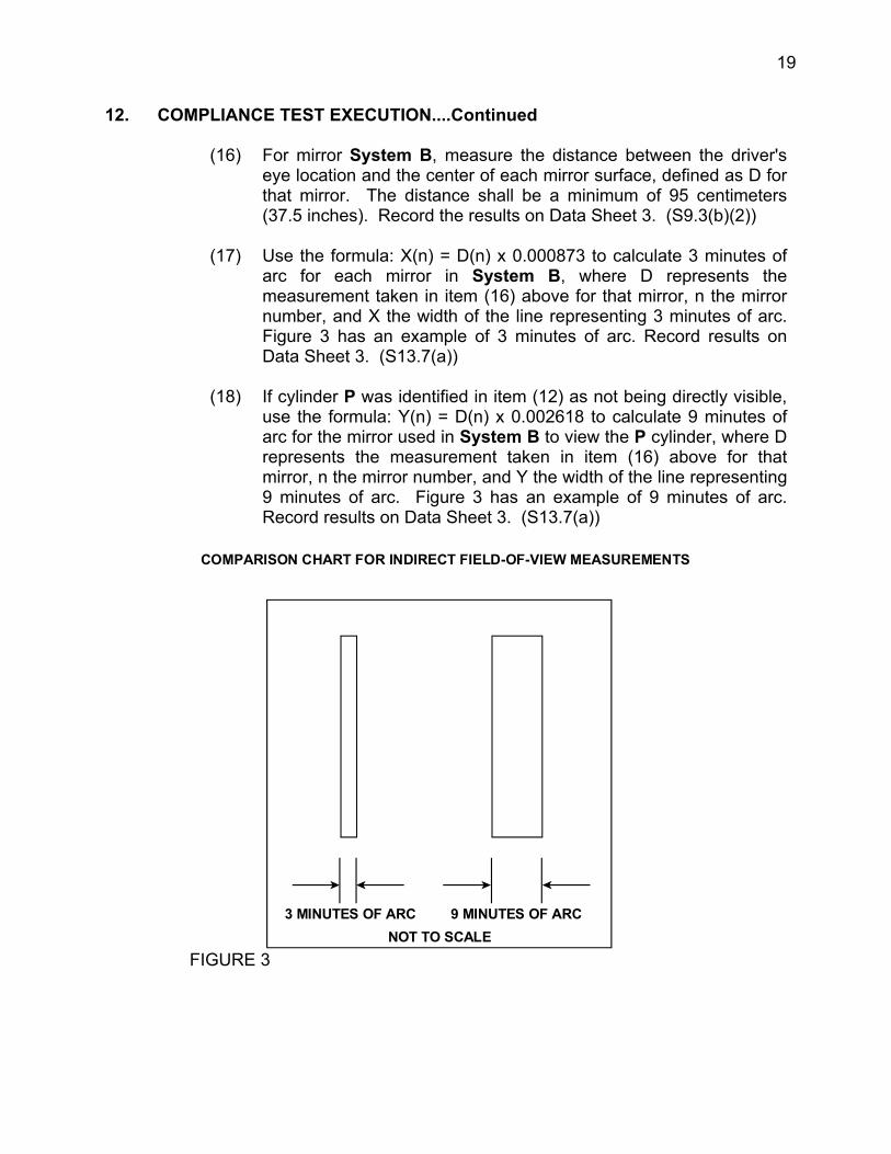
(17) Use the formula: X(n) = D(n) x 0.000873 to calculate 3 minutes of arc for each mirror in System B, where D represents the measurement taken in item (16) above for that mirror, n the mirror number, and X the width of the line representing 3 minutes of arc. Figure 3 has an example of 3 minutes of arc. Record results on Data Sheet 3. (S13.7(a))
(18) If cylinder P was identified in item (12) as not being directly visible, use the formula: Y(n) = D(n) x 0.002618 to calculate 9 minutes of arc for the mirror used in System B to view the P cylinder, where D represents the measurement taken in item (16) above for that mirror, n the mirror number, and Y the width of the line representing 9 minutes of arc. Figure 3 has an example of 9 minutes of arc. Record results on Data Sheet 3. (S13.7(a))
COMPARISON CHART FOR INDIRECT FIELD-OF-VIEW MEASUREMENTS
NOT TO SCALE 3 MINUTES OF ARC 9 MINUTES OF ARC
FIGURE 3
20
12. COMPLIANCE TEST EXECUTION....Continued
(19) Make a comparison chart for 9 minutes of arc from item (18) on previous page for the mirror used to view the P cylinder and label it with print readable in any photograph that is taken of it.
(20) Make a comparison chart for 3 minutes of arc for each System Bmirror and label it with print readable in any photograph that is taken of it.
(21) Place the comparison charts from the previous items (19) and (20) next to each System B mirror at each mirror's D(n) distance from the driver's eye location. The comparison charts should be visible in all field-of-view photographs. (S13.7(a))
(22) For those cylinders identified in item (12) - not directly visible without mirrors, photograph each cylinder through the mirror(s) that provides a view of the cylinder. Photograph each cylinder with the camera located so that the view through its film or image plane is located at any single location within the semicircle established in item (10) above ensuring that the image of the mirror and comparison chart fill the camera’s view finder to the extent possible. Record the results of the visibility of the cylinders photographed in Data Sheet 4. (S13.7(b))
(23) Identify the 3 minute chart in each photograph above, and using a measuring device, determine that the image produced by the entire top surface of those cylinders identified in item (12), are separated from the edge of the effective mirror surface of the mirror providing that image by a distance of not less than 3 minutes of arc. Record the results in Data Sheet 4. (S9.4(a))
(24) If cylinder P is identified in item (12) - not directly visible, identify the 3 minute and 9 minute charts in the photograph used to view the P cylinder. Using a measuring device, determine that the angular size of the shortest dimension of that cylinder’s image is not less than 3 minutes of arc, and the angular size of the longest dimension of that cylinder’s image is not less than 9 minutes of arc.. Record the results in Data Sheet 4. (S9.4(b))
21
12. COMPLIANCE TEST EXECUTION....Continued
(25) By inspecting the photographs from System A and B mirrors, determine that System B mirror field-of-views of the ground overlap with the view of the ground provided by System A. Record the results on Data Sheet 4. (S9.3(a)(2).
(26) Mirror stabilities, continuities, and sharp protrusions.
(A) Determine if System A mirrors have stable supports. Record the results on Data Sheet 5. (S9.2)
(B) Determine if System B mirrors have stable supports. Record the results on Data Sheet 5. (S9.3(b)(4))
(C) Determine that System B mirrors have no discontinuities in the slope of the surface of the mirror. Record results on Data Sheet 5. (S9.3(b)(3).
(D) Determine that all outside mirrors are free of sharp points or edges that could contribute to pedestrian injury. Record results on Data Sheet 5.
(27) Remove all System A and B mirrors from the bus.
(28) Perform the Reflectance Test on all System A and B mirrors as shown in Appendix 1. Record the results on Data Sheet 6. (S.11)
Duplicate copies of the Data Sheet should be made with each mirror identified on a Data Sheet.
(29) Unit Magnification and Radius of Curvature Tests
(A) Perform items (A) through (F) of the Unit Magnification/ Convex Mirror Test on all System A and System B mirrors as shown in Appendix 2. Record the results on Data Sheet 7. At least one System A mirror on each side of the bus must be unit magnification. (S9.2(a)). Unit magnification mirrors have 0 radius of curvature.
Duplicate copies of the Data Sheet should be made with each mirror identified on a Data Sheet.
22
12. COMPLIANCE TEST EXECUTION....Continued
(B) If any of the convex mirrors in System B have a average radius of curvature of less than 889 mm, then observe that the following words are on a label printed in type face and color that are clear and conspicuous to the driver (S9.3(c)):
"USE CROSS VIEW MIRRORS TO VIEW PEDESTRIANS WHILE BUS IS STOPPED. DO NOT USE THESE MIRRORS TO VIEW TRAFFIC WHILE BUS IS MOVING, IMAGES IN SUCH MIRRORS DO NOT ACCURATELY SHOW ANOTHER VEHICLE'S LOCATION."
Record the results on Data Sheet 7.
(30) Mirror Surface Area Tests
(A) Measure the reflective surface area of the System A mirrors. At least one System A mirror on each side of the bus must be unit magnification with not less than 323 cm squared of reflective surface. (S9.2(a)) Record the results on Data Sheet 8.
(B) Measure the projected area of the System B mirrors on a plane at a right angle to the mirrors' axis. Each mirror must have a projected area of at least 258 cm squared. (S9.3(b)(1)) Record the results on Data Sheet 8.
23
13. POST TEST REQUIREMENTS
After the required tests are completed, the contractor shall:
A. Re-install all mirrors in original locations.
B. Verify all instrumentation, data sheets and photographs,
C. Complete the Vehicle Condition report form including a word description of its post test condition
D. Copy applicable pages of the vehicle Owner's Manual for attachment to the final test report
E. Move the test vehicle to a secure area, and
F. Place all original records in a secure and organized file awaiting test data disposition.
14. REPORTS
14.1 MONTHLY STATUS REPORTS
The contractor shall submit a monthly Test Status Report to the COTR. The report shall be submitted until all vehicles are disposed of. Samples of the required reports are found in the report forms section.
14.2 APPARENT TEST FAILURE
Any indication of a test failure shall be communicated by telephone, e-mail, or facsimile to the COTR within 24 hours with written notification mailed within 48 hours (Saturday and Sunday hours excluded). A Notice of Test Failure (see report forms section) with a copy of the particular compliance test data sheet(s) and preliminary data plot(s) shall be included. If possible repeat that portion of the test where the failure was noted to ensure that there is a test failure. In the event of a test failure, a post test calibration check of some critically sensitive test equipment and instrumentation may be required for verification of accuracy. The necessity for the calibration shall be at the COTR's discretion and shall be performed without additional costs to the OVSC.

24
14. REPORTS....Continued
14.3 FINAL TEST REPORTS
14.3.1 COPIES
In the case of an apparent test failure, FIVE (5) paper copies and a computer diskette of the Final Test Report shall be submitted to the COTR for acceptance within 3 weeks of test completion. The Final Test Report format to be used by all contractors can be found in the "Report Section".
Where there has been no indication of an apparent noncompliance, TWO (2) paper copies and a computer diskette of each Final Test Report shall be submitted to the COTR for acceptance within 3 weeks of test completion. No payment of contractor's invoices for conducting compliance tests will be made prior to the Final Test Report acceptance by the COTR. Contractors are requested to NOT submit invoices before the COTR is provided with copies of the Final Test Report. Contractors are required to submit the first Final Test Report in draft form within 1 week after the compliance test is conducted. The contractor and the COTR will then be able to discuss the details of both test conduct and report content early in the compliance test program.
Contractors are required to PROOF READ all Final Test Reports before submittal to the COTR. The OVSC will not act as a report quality control office for contractors. Reports containing a significant number of errors will be returned to the contractor for correction, and a "hold" will be placed on invoice payment for the particular test.
14.3.2 REQUIREMENTS
The Final Test Report, associated documentation (including photographs), are relied upon as the chronicle of the compliance test. The Final Test Report will be released to the public domain after review and acceptance by the COTR. For these reasons, each final report must be a complete document capable of standing by itself.
The contractor should use DETAILED descriptions of all compliance test events. Any events that are not directly associated with the standard but are of technical interest should also be included. The contractor should include as much DETAIL as possible in the report.
Instructions for the preparation of the first three pages of the final test report are provided for standardization.
25
14. REPORTS....Continued
14.3.3 FIRST THREE PAGES
A. FRONT COVER
A heavy paperback cover (or transparency) shall be provided for the protection of the final report. The information required on the cover is as follows:
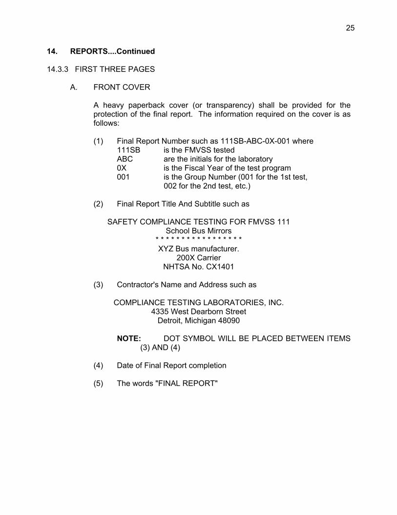
(1) Final Report Number such as 111SB-ABC-0X-001 where 111SB is the FMVSS tested ABC are the initials for the laboratory 0X is the Fiscal Year of the test program 001 is the Group Number (001 for the 1st test,
002 for the 2nd test, etc.)
(2) Final Report Title And Subtitle such as
SAFETY COMPLIANCE TESTING FOR FMVSS 111School Bus Mirrors
* * * * * * * * * * * * * * * * * XYZ Bus manufacturer.
200X Carrier NHTSA No. CX1401
(3) Contractor's Name and Address such as
COMPLIANCE TESTING LABORATORIES, INC. 4335 West Dearborn Street
Detroit, Michigan 48090
NOTE: DOT SYMBOL WILL BE PLACED BETWEEN ITEMS (3) AND (4)
(4) Date of Final Report completion
(5) The words "FINAL REPORT"
26
14. REPORTS....Continued
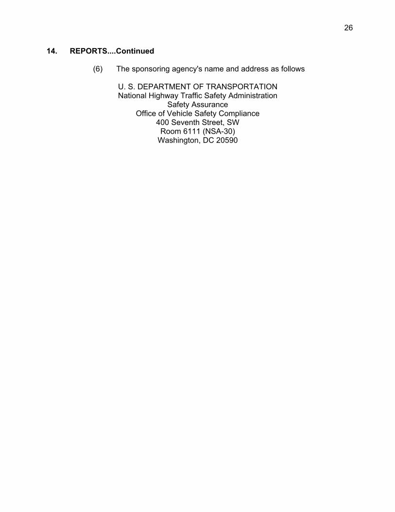
(6) The sponsoring agency's name and address as follows
U. S. DEPARTMENT OF TRANSPORTATION National Highway Traffic Safety Administration
Safety Assurance Office of Vehicle Safety Compliance
400 Seventh Street, SW Room 6111 (NSA-30)
Washington, DC 20590

27
14. REPORTS....Continued
B. FIRST PAGE AFTER FRONT COVER
A disclaimer statement and an acceptance signature block for the COTR shall be provided as follows
This publication is distributed by the U.S. Department of Transportation, National Highway Traffic Safety Administration, in the interest of information exchange. The opinions, findings and conclusions expressed in this publication are those of the author(s) and not necessarily those of the Department of Transportation or the National Highway Traffic Safety Administration. The United States Government assumes no liability for its contents or use thereof. If trade or manufacturers' names or products are mentioned, it is only because they are considered essential to the object of the publication and should not be construed as an endorsement. The United States Government does not endorse products or manufacturers.
Prepared By: ________________________
Approved By: ________________________
Approval Date: _______________________
FINAL REPORT ACCEPTANCE BY OVSC:
Accepted By: ________________________
Acceptance Date: ____________________
28
14. REPORTS....Continued
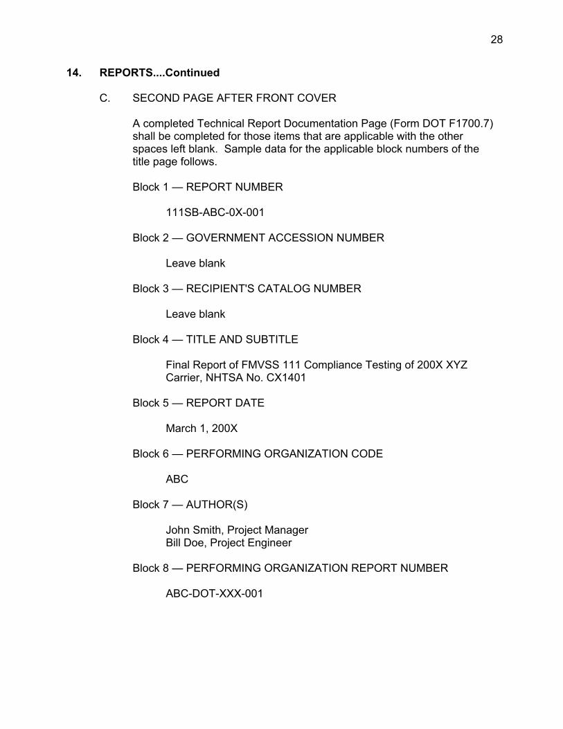
C. SECOND PAGE AFTER FRONT COVER
A completed Technical Report Documentation Page (Form DOT F1700.7) shall be completed for those items that are applicable with the other spaces left blank. Sample data for the applicable block numbers of the title page follows.
Block 1 — REPORT NUMBER
111SB-ABC-0X-001
Block 2 — GOVERNMENT ACCESSION NUMBER
Leave blank
Block 3 — RECIPIENT'S CATALOG NUMBER
Leave blank
Block 4 — TITLE AND SUBTITLE
Final Report of FMVSS 111 Compliance Testing of 200X XYZ Carrier, NHTSA No. CX1401
Block 5 — REPORT DATE
March 1, 200X
Block 6 — PERFORMING ORGANIZATION CODE
ABC
Block 7 — AUTHOR(S)
John Smith, Project Manager Bill Doe, Project Engineer
Block 8 — PERFORMING ORGANIZATION REPORT NUMBER
ABC-DOT-XXX-001
29
14. REPORTS....Continued
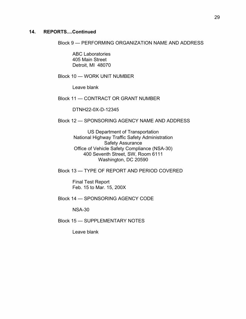
Block 9 — PERFORMING ORGANIZATION NAME AND ADDRESS
ABC Laboratories 405 Main Street Detroit, MI 48070
Block 10 — WORK UNIT NUMBER
Leave blank
Block 11 — CONTRACT OR GRANT NUMBER
DTNH22-0X-D-12345
Block 12 — SPONSORING AGENCY NAME AND ADDRESS
US Department of Transportation National Highway Traffic Safety Administration
Safety Assurance Office of Vehicle Safety Compliance (NSA-30)
400 Seventh Street, SW, Room 6111 Washington, DC 20590
Block 13 — TYPE OF REPORT AND PERIOD COVERED
Final Test Report Feb. 15 to Mar. 15, 200X
Block 14 — SPONSORING AGENCY CODE
NSA-30
Block 15 — SUPPLEMENTARY NOTES
Leave blank
30
14. REPORTS....Continued
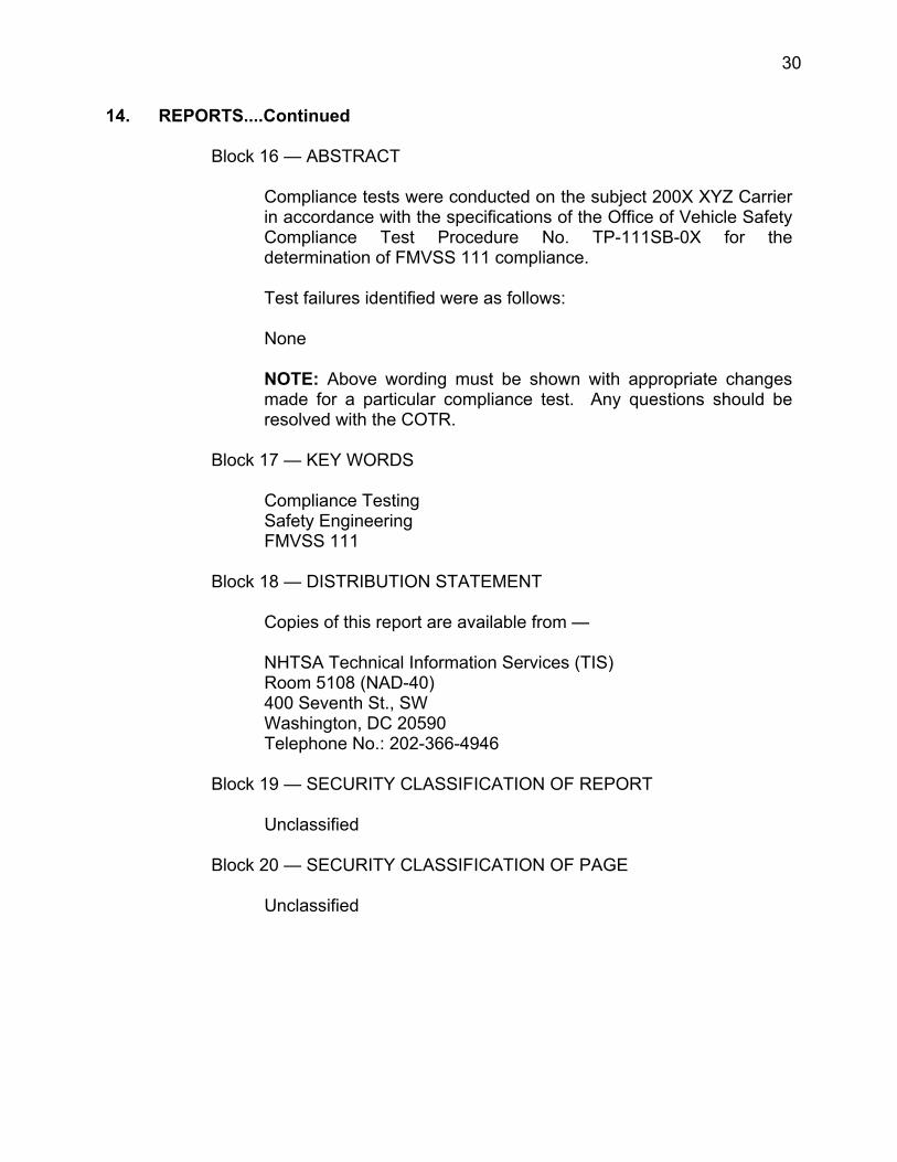
Block 16 — ABSTRACT
Compliance tests were conducted on the subject 200X XYZ Carrier in accordance with the specifications of the Office of Vehicle Safety Compliance Test Procedure No. TP-111SB-0X for the determination of FMVSS 111 compliance.
Test failures identified were as follows:
None
NOTE: Above wording must be shown with appropriate changes made for a particular compliance test. Any questions should be resolved with the COTR.
Block 17 — KEY WORDS
Compliance Testing Safety Engineering FMVSS 111
Block 18 — DISTRIBUTION STATEMENT
Copies of this report are available from —
NHTSA Technical Information Services (TIS)Room 5108 (NAD-40) 400 Seventh St., SW Washington, DC 20590 Telephone No.: 202-366-4946
Block 19 — SECURITY CLASSIFICATION OF REPORT
Unclassified
Block 20 — SECURITY CLASSIFICATION OF PAGE
Unclassified
31
14. REPORTS....Continued
Block 21 — NUMBER OF PAGES
Add appropriate number
Block 22 — PRICE
Leave blank
14.3.4 TABLE OF CONTENTS
The final test report Table Of Contents shall include the following as a minimum:
Section 1 — Purpose of Compliance Test
Section 2 — Test Procedure and Discussion of Results
Section 3 — Compliance Test Data
Section 4 — Test Equipment List and Calibration Information
Section 5 — Photographs
Section 6 — Notice of Test Failure (if applicable)
Section 7 — Vehicle Owner’s Manual (applicable pages)
32
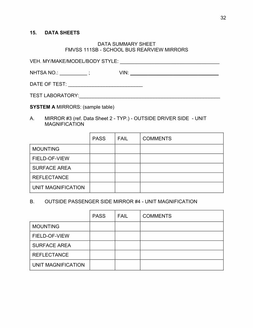
15. DATA SHEETS
DATA SUMMARY SHEET FMVSS 111SB - SCHOOL BUS REARVIEW MIRRORS
VEH. MY/MAKE/MODEL/BODY STYLE: ____________________________________
NHTSA NO.: ; VIN: ________________________________
DATE OF TEST: ___________________________
TEST LABORATORY:___________________________________________________
SYSTEM A MIRRORS: (sample table)
A. MIRROR #3 (ref. Data Sheet 2 - TYP.) - OUTSIDE DRIVER SIDE - UNIT MAGNIFICATION
PASS FAIL COMMENTS
MOUNTING
FIELD-OF-VIEW
SURFACE AREA
REFLECTANCE
UNIT MAGNIFICATION
B. OUTSIDE PASSENGER SIDE MIRROR #4 - UNIT MAGNIFICATION
PASS FAIL COMMENTS
MOUNTING
FIELD-OF-VIEW
SURFACE AREA
REFLECTANCE
UNIT MAGNIFICATION
33
15. DATA SHEETS....Continued
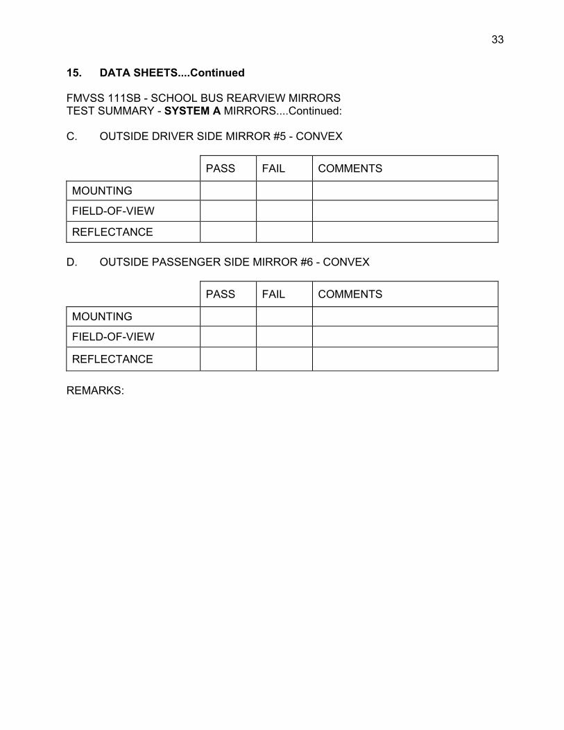
FMVSS 111SB - SCHOOL BUS REARVIEW MIRRORS TEST SUMMARY - SYSTEM A MIRRORS....Continued:
C. OUTSIDE DRIVER SIDE MIRROR #5 - CONVEX
PASS FAIL COMMENTS
MOUNTING
FIELD-OF-VIEW
REFLECTANCE
D. OUTSIDE PASSENGER SIDE MIRROR #6 - CONVEX
PASS FAIL COMMENTS
MOUNTING
FIELD-OF-VIEW
REFLECTANCE
REMARKS:
34
15. DATA SHEETS....Continued
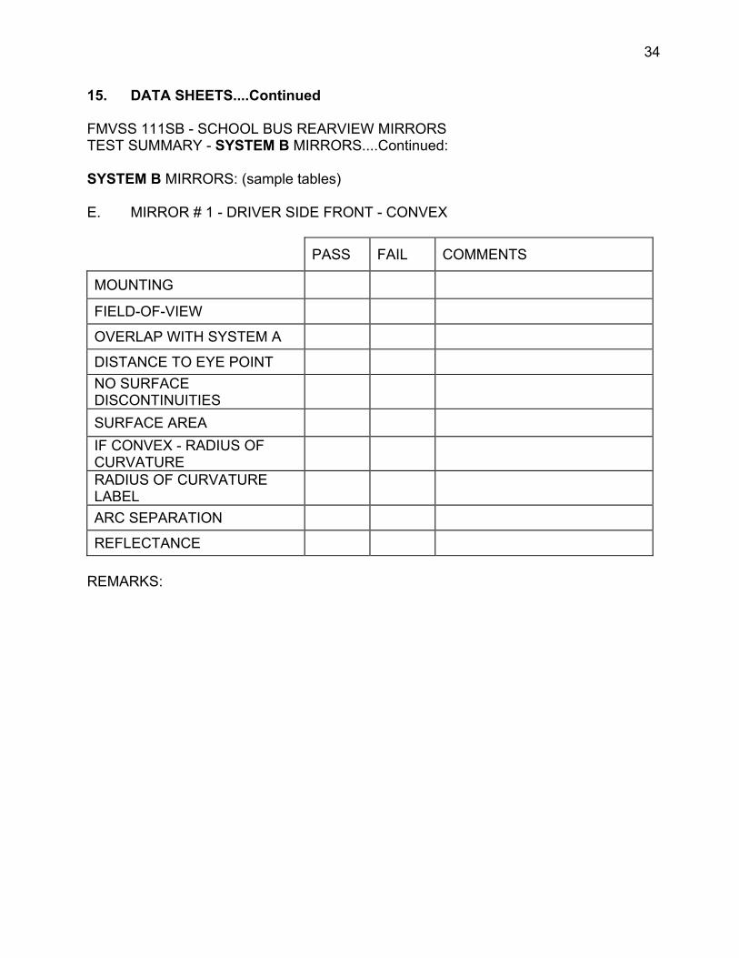
FMVSS 111SB - SCHOOL BUS REARVIEW MIRRORS TEST SUMMARY - SYSTEM B MIRRORS....Continued:
SYSTEM B MIRRORS: (sample tables)
E. MIRROR # 1 - DRIVER SIDE FRONT - CONVEX
PASS FAIL COMMENTS
MOUNTING
FIELD-OF-VIEW
OVERLAP WITH SYSTEM A
DISTANCE TO EYE POINT NO SURFACE DISCONTINUITIES SURFACE AREA IF CONVEX - RADIUS OF CURVATURE RADIUS OF CURVATURE LABEL ARC SEPARATION
REFLECTANCE
REMARKS:

35
15. DATA SHEETS....Continued
FMVSS 111SB - SCHOOL BUS REARVIEW MIRRORS TEST SUMMARY - SYSTEM B MIRRORS.....Continued:
F. PASSENGER SIDE FRONT MIRROR #2 - CONVEX
PASS FAIL COMMENTS
MOUNTING
FIELD-OF-VIEW
OVERLAP WITH SYSTEM A
DISTANCE TO EYE POINT NO SURFACE DISCONTINUITIES SURFACE AREA IF CONVEX - RADIUS OF CURVATURE RADIUS OF CURVATURE LABEL ARC SEPARATION
REFLECTANCE
REMARKS:
36
15. DATA SHEETS....Continued
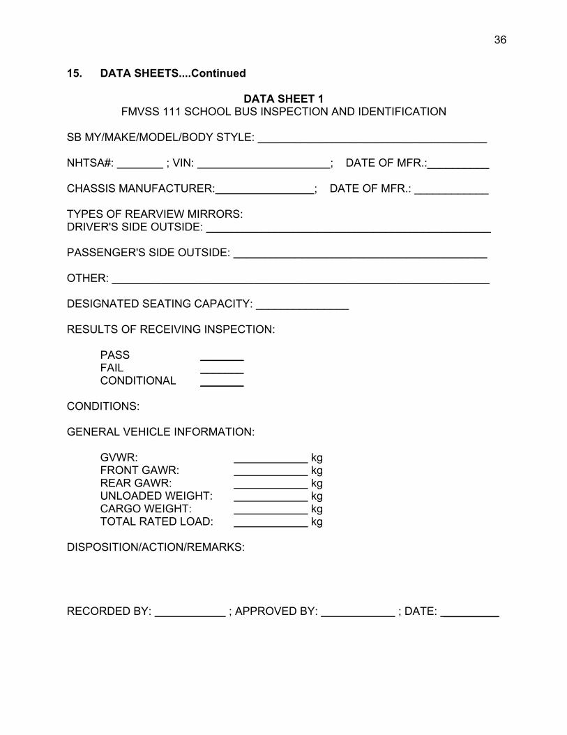
DATA SHEET 1 FMVSS 111 SCHOOL BUS INSPECTION AND IDENTIFICATION
SB MY/MAKE/MODEL/BODY STYLE: _____________________________________
NHTSA#: ; VIN: ; DATE OF MFR.:__________
CHASSIS MANUFACTURER: ; DATE OF MFR.: ____________
TYPES OF REARVIEW MIRRORS: DRIVER'S SIDE OUTSIDE: ______________________________________________
PASSENGER'S SIDE OUTSIDE: _________________________________________
OTHER: _____________________________________________________________
DESIGNATED SEATING CAPACITY: _______________
RESULTS OF RECEIVING INSPECTION:
PASS _______ FAIL _______ CONDITIONAL _______
CONDITIONS:
GENERAL VEHICLE INFORMATION:
GVWR: kg FRONT GAWR: kg REAR GAWR: kg UNLOADED WEIGHT: kg CARGO WEIGHT: kg TOTAL RATED LOAD: kg
DISPOSITION/ACTION/REMARKS:
RECORDED BY: ; APPROVED BY: ; DATE: _________
1
2
3
4
5
6
---------------------------------------------------------------------------------------------------------------------
37
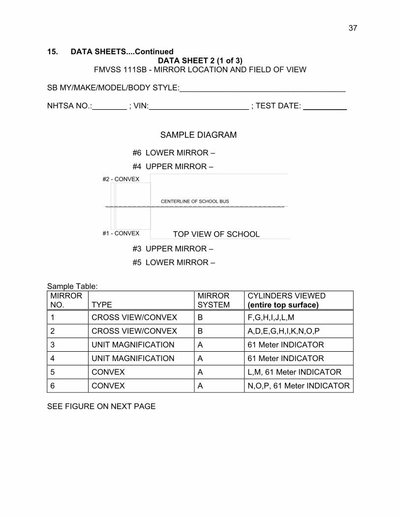
15. DATA SHEETS....Continued DATA SHEET 2 (1 of 3)
FMVSS 111SB - MIRROR LOCATION AND FIELD OF VIEW
SB MY/MAKE/MODEL/BODY STYLE:______________________________________
NHTSA NO.: ; VIN: ; TEST DATE: __________
SAMPLE DIAGRAM
#6 LOWER MIRROR –
#4 UPPER MIRROR – #2 - CONVEX
CENTERLINE OF SCHOOL BUS
TOP VIEW OF SCHOOL #1 - CONVEX
#3 UPPER MIRROR –
#5 LOWER MIRROR –
Sample Table: MIRROR NO. TYPE
MIRROR SYSTEM
CYLINDERS VIEWED (entire top surface)
VIEW/CONVEX B F,G,H,I,J,L,M
VIEW/CONVEX B A,D,E,G,H,I,K,N,O,P
UNIT MAGNIFICATION A 61 Meter INDICATOR
UNIT MAGNIFICATION A 61 Meter INDICATOR
CONVEX A L,M, 61 Meter INDICATOR
CONVEX A N,O,P, 61 Meter INDICATOR
CROSS
CROSS
SEE FIGURE ON NEXT PAGE
38
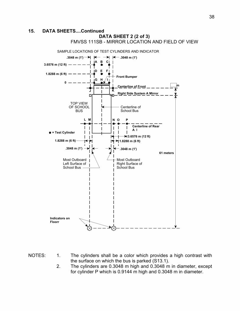
15. DATA SHEETS....Continued DATA SHEET 2 (2 of 3)
FMVSS 111SB - MIRROR LOCATION AND FIELD OF VIEW
SAMPLE LOCATIONS OF TEST CYLINDERS AND INDICATOR .3048 m (1')
3.6576 m (12 ft)
1.8288 m (6 ft)
0
C .3048 m (1')
A B
m J K
L M N O P
3.6576 m (12 ft)
Centerline of Front A l
D E F
G H I
Right Side System A Mirror S f
Front Bumper
Centerline of School Bus
TOP VIEW OF SCHOOL
BUS
61 meters
Centerline of Rear A l
1.8288 m (6 ft)
.3048 m (1')
Most Outboard Right Surface of School Bus
= Test Cylinder
1.8288 m (6 ft)
.3048 m (1')
Most Outboard Left Surface of School Bus
Indicators on Floorr
NOTES: 1. The cylinders shall be a color which provides a high contrast with the surface on which the bus is parked (S13.1).
2. The cylinders are 0.3048 m high and 0.3048 m in diameter, except for cylinder P which is 0.9144 m high and 0.3048 m in diameter.
39
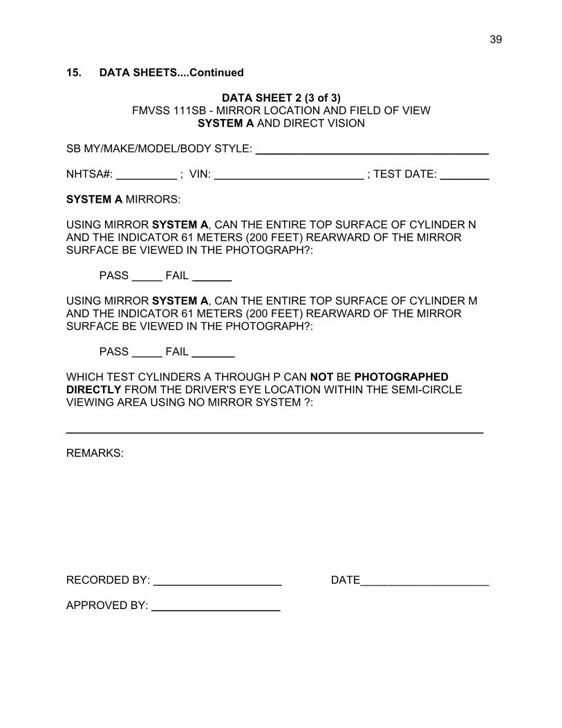
15. DATA SHEETS....Continued
DATA SHEET 2 (3 of 3)FMVSS 111SB - MIRROR LOCATION AND FIELD OF VIEW
SYSTEM A AND DIRECT VISION
SB MY/MAKE/MODEL/BODY STYLE: ______________________________________
NHTSA#: ; VIN: ; TEST DATE: ________
SYSTEM A MIRRORS:
USING MIRROR SYSTEM A, CAN THE ENTIRE TOP SURFACE OF CYLINDER N AND THE INDICATOR 61 METERS (200 FEET) REARWARD OF THE MIRROR SURFACE BE VIEWED IN THE PHOTOGRAPH?:
PASS FAIL ______
USING MIRROR SYSTEM A, CAN THE ENTIRE TOP SURFACE OF CYLINDER M AND THE INDICATOR 61 METERS (200 FEET) REARWARD OF THE MIRROR SURFACE BE VIEWED IN THE PHOTOGRAPH?:
PASS FAIL _______
WHICH TEST CYLINDERS A THROUGH P CAN NOT BE PHOTOGRAPHED DIRECTLY FROM THE DRIVER'S EYE LOCATION WITHIN THE SEMI-CIRCLE VIEWING AREA USING NO MIRROR SYSTEM ?:
____________________________________________________________________
REMARKS:
RECORDED BY: DATE_____________________
APPROVED BY: _____________________
40
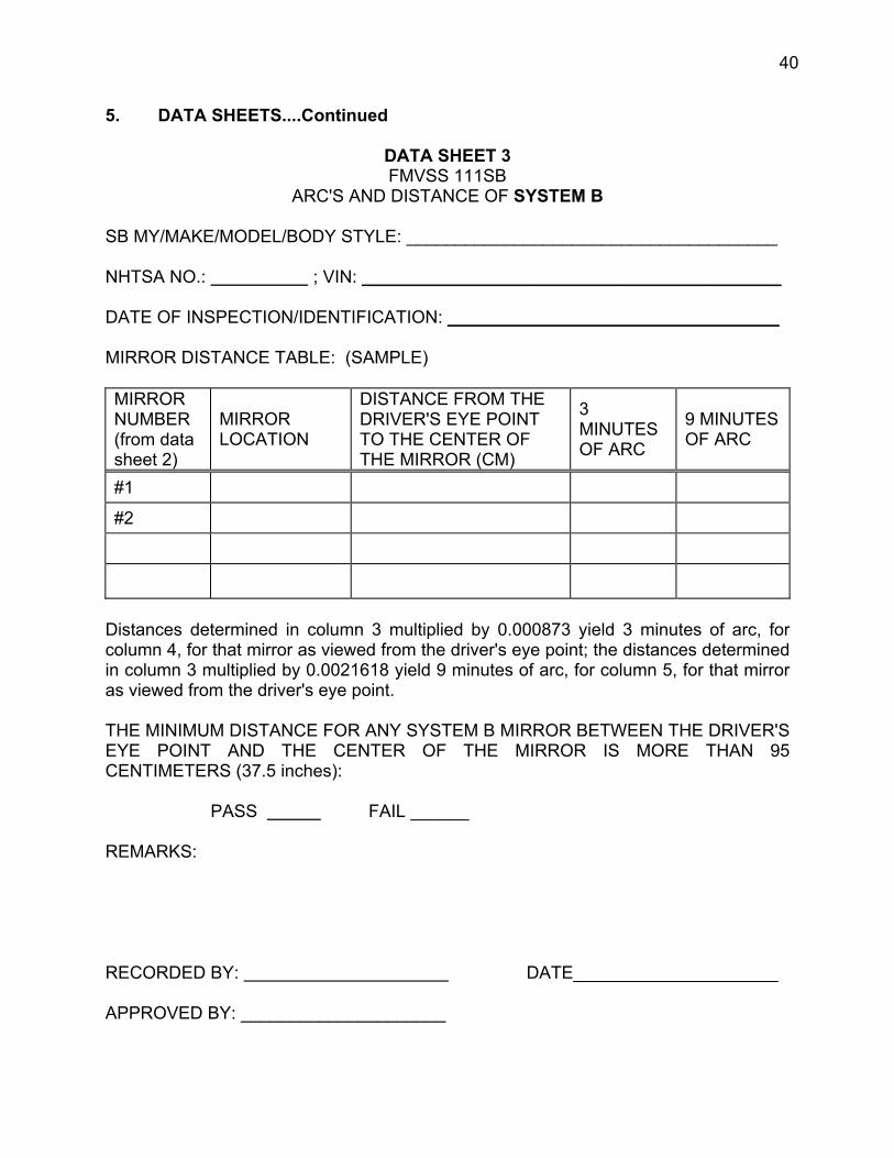
5. DATA SHEETS....Continued
DATA SHEET 3 FMVSS 111SB
ARC'S AND DISTANCE OF SYSTEM B
SB MY/MAKE/MODEL/BODY STYLE: ______________________________________
NHTSA NO.: ; VIN: ___________________________________________
DATE OF INSPECTION/IDENTIFICATION: __________________________________
MIRROR DISTANCE TABLE: (SAMPLE)
MIRROR NUMBER (from data sheet 2)
MIRROR LOCATION
DISTANCE FROM THE DRIVER'S EYE POINT TO THE CENTER OF THE MIRROR (CM)
3 MINUTES OF ARC
9 MINUTES OF ARC
#1
#2
Distances determined in column 3 multiplied by 0.000873 yield 3 minutes of arc, for column 4, for that mirror as viewed from the driver's eye point; the distances determined in column 3 multiplied by 0.0021618 yield 9 minutes of arc, for column 5, for that mirror as viewed from the driver's eye point.
THE MINIMUM DISTANCE FOR ANY SYSTEM B MIRROR BETWEEN THE DRIVER'S EYE POINT AND THE CENTER OF THE MIRROR IS MORE THAN 95 CENTIMETERS (37.5 inches):
PASS FAIL ______
REMARKS:
RECORDED BY: DATE_____________________
APPROVED BY: _____________________

41
15. DATA SHEETS....Continued
DATA SHEET 4 FMVSS 111SB - FIELD OF VIEW TEST - PHOTOGRAPHS
SYSTEM B SB MY/MAKE/MODEL/BODY STYLE: ______________________________________ NHTSA#: ; VIN: ; TEST DATE: ___________
ALL TEST CYLINDERS WITH ENTIRE TOP SURFACE NOT DIRECTLY VISIBLE FROM THE DRIVER'S SEMI-CIRCLE EYE LOCATION ARE ABLE TO BE VIEWED WITH SYSTEM B MIRRORS FROM THE DRIVER'S SEMI-CIRCLE EYE LOCATION:
PASS FAIL ______
ALL TEST CYLINDERS WITH ENTIRE TOP SURFACE NOT DIRECTLY VISIBLE FROM THE DRIVER'S SEMI-CIRCLE EYE LOCATION BUT THE IMAGE CAN BE VIEWED WITH SYSTEM B MIRRORS, THE IMAGE IS SEPARATED FOR THE EDGE OF THE EFFECTIVE MIRROR SURFACE OF THE MIRROR PROVIDING THAT IMAGE BY A DISTANCE OF NOT LESS THAN 3 MINUTES OF ARC:
PASS FAIL ______
IF ENTIRE TOP SURFACE OF TEST CYLINDER P IS NOT DIRECTLY VISIBLE FROM THE DRIVER'S SEMI-CIRCLE EYE LOCATION, THE IMAGE CAN BE VIEWED WITH SYSTEM B MIRRORS FROM THE DRIVER'S SEMI-CIRCLE EYE LOCATION, WHERE THE ANGULAR SIZE OF THE SHORTEST DIMENSION OF THAT CYLINDER’S IMAGE IS NOT LESS THAN 3 MINUTES OF ARC, AND THE ANGULAR SIZE OF THE LONGEST DIMENSION OF THAT CYLINDER’S IMAGE IS NOT LESS THAN 9 MINUTES OF ARC:
SHORTEST ARC LENGTH DIMENSION: __________________________________ LONGEST ARC LENGTH DIMENSION: ___________________________________
PASS FAIL N/A ________
FOR EACH OF THE TEST CYLINDERS WHOSE ENTIRE TOP SURFACE IS NOT DIRECTLY VISIBLE FROM THE DRIVER’S EYE LOCATION, SYSTEM B PROVIDES A VIEW OF THE GROUND THAT OVERLAPS WITH THE VIEW OF THE GROUND PROVIDED BY SYSTEM A
PASS FAIL ______
TEST RESULTS: PASS FAIL ______
RECORDED BY: APPROVED BY: ____________ DATE: __________

1
2
3
4
5
6
42
15. DATA SHEETS....Continued
DATA SHEET 5 FMVSS111SB - MOUNTING ADEQUACY TEST
ALL MIRRORS
SB MY/MAKE/MODEL/BODY STYLE: _____________________________________
NHTSA#: ; VIN: ; TEST DATE: ___________
MIRROR MOUNTING PROVIDES A STABLE SUPPORT: (SAMPLE TABLE)
MIRROR NO. (from data sheet 2)
TYPE SYSTEM STABLE SUPPORT
YES NO
VIEW/CONVEX B
VIEW/CONVEX B
MAGNIFICATION A
MAGNIFICATION A
X A
X A
CROSS
CROSS
UNIT
UNIT
CONVE
CONVE
PASS FAIL
OUTSIDE MIRRORS FREE OF SHARP POINTS OR EDGES THAT COULD CONTRIBUTE TO PEDESTRIAN INJURY: PASS FAIL ____
SYSTEM B MIRRORS HAVE NO DISCONTINUITIES IN THE SLOPE OF THE SURFACE OF THE MIRROR: PASS FAIL _______
TEST RESULTS: PASS FAIL ______
REMARKS:
RECORDED BY: ; APPROVED BY: ; DATE: __________
43
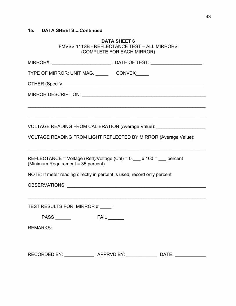
15. DATA SHEETS....Continued
DATA SHEET 6 FMVSS 111SB - REFLECTANCE TEST – ALL MIRRORS
(COMPLETE FOR EACH MIRROR)
MIRROR#: _______________________ ; DATE OF TEST: ____________________
TYPE OF MIRROR: UNIT MAG. CONVEX_____
OTHER (Specify_______________________________________________________
MIRROR DESCRIPTION: ________________________________________________
_____________________________________________________________________
_____________________________________________________________________
VOLTAGE READING FROM CALIBRATION (Average Value): ___________________
VOLTAGE READING FROM LIGHT REFLECTED BY MIRROR (Average Value):
_____________________________________________________________________
REFLECTANCE = Voltage (Refl)/Voltage (Cal) = 0. x 100 = percent (Minimum Requirement = 35 percent)
NOTE: If meter reading directly in percent is used, record only percent
OBSERVATIONS: ______________________________________________________
_____________________________________________________________________
TEST RESULTS FOR MIRROR # :
PASS FAIL ______
REMARKS:
RECORDED BY: APPRVD BY: ____________ DATE: ____________
1
2
3
4
5
6
7
8
9
10
44
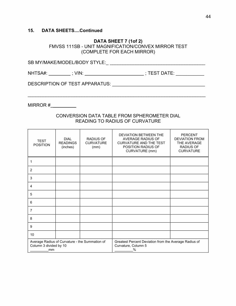
15. DATA SHEETS....Continued
DATA SHEET 7 (1of 2)FMVSS 111SB - UNIT MAGNIFICATION/CONVEX MIRROR TEST
(COMPLETE FOR EACH MIRROR)
SB MY/MAKE/MODEL/BODY STYLE:_ _____________________________________
NHTSA#: ; VIN: ; TEST DATE: ___________
DESCRIPTION OF TEST APPARATUS: ____________________________________
_____________________________________________________________________
MIRROR # _________
CONVERSION DATA TABLE FROM SPHEROMETER DIAL READING TO RADIUS OF CURVATURE
TEST POSITION
DIAL READINGS
(inches)
RADIUS OF CURVATURE
(mm)
DEVIATION BETWEEN THE AVERAGE RADIUS OF
CURVATURE AND THE TEST POSITION RADIUS OF
CURVATURE (mm)
PERCENT DEVIATION FROM
THE AVERAGE RADIUS OF
CURVATURE
Average Radius of Curvature - the Summation of Column 3 divided by 10
mm
Greatest Percent Deviation from the Average Radius of Curvature, Column 5
%
45
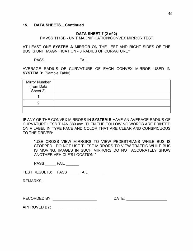
15. DATA SHEETS....Continued
DATA SHEET 7 (2 of 2)FMVSS 111SB - UNIT MAGNIFICATION/CONVEX MIRROR TEST
AT LEAST ONE SYSTEM A MIRROR ON THE LEFT AND RIGHT SIDES OF THE BUS IS UNIT MAGNIFICATION - 0 RADIUS OF CURVATURE?
PASS _________ FAIL _________
AVERAGE RADIUS OF CURVATURE OF EACH CONVEX MIRROR USED IN SYSTEM B: (Sample Table)
Mirror Number (from Data Sheet 2)
1
2
IF ANY OF THE CONVEX MIRRORS IN SYSTEM B HAVE AN AVERAGE RADIUS OF CURVATURE LESS THAN 889 mm, THEN THE FOLLOWING WORDS ARE PRINTED ON A LABEL IN TYPE FACE AND COLOR THAT ARE CLEAR AND CONSPICUOUS TO THE DRIVER:
"USE CROSS VIEW MIRRORS TO VIEW PEDESTRIANS WHILE BUS IS STOPPED. DO NOT USE THESE MIRRORS TO VIEW TRAFFIC WHILE BUS IS MOVING, IMAGES IN SUCH MIRRORS DO NOT ACCURATELY SHOW ANOTHER VEHICLE'S LOCATION."
PASS FAIL ______
TEST RESULTS: PASS FAIL _______
REMARKS:
RECORDED BY: DATE: ___________________
APPROVED BY: _____________________

46
15. DATA SHEETS....Continued
DATA SHEET 8 FMVSS 111SB - MIRROR REFLECTIVE SURFACE AREA TEST
SYSTEMS A & B
SB MY/MAKE/MODEL/BODY STYLE:______________________________________
NHTSA#: ; VIN: ; TEST DATE: ____________
DATA TABLE FOR SURFACE AREA [SAMPLE TABLE - A AND B MAY VARY]
SYSTEM A MIRRORS MIRROR # AREA
REQUIREMENT min. 323 CM2 PASS/FAIL
Driver Outside, unit magnification #3
Passenger Outside, unit magnification # 4
SYSTEM B MIRRORS MIRROR # AREA
REQUIREMENT min. 258CM2 PASS/FAIL
Convex, Driver Outside Crossview #1
Convex, Passenger Outside, Crossview #2
TEST RESULTS: PASS FAIL _________
REMARKS:
RECORDED BY: DATE: _____________________
APPROVED BY: _____________________
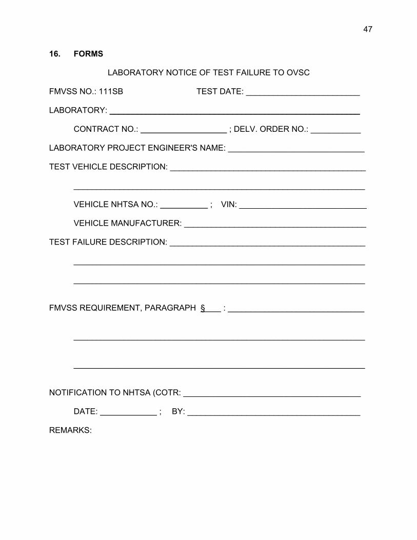
47
16. FORMS
LABORATORY NOTICE OF TEST FAILURE TO OVSC
FMVSS NO.: 111SB TEST DATE: _________________________
LABORATORY: _______________________________________________________
CONTRACT NO.: ; DELV. ORDER NO.: ___________
LABORATORY PROJECT ENGINEER'S NAME: ______________________________
TEST VEHICLE DESCRIPTION: ___________________________________________
________________________________________________________________
VEHICLE NHTSA NO.: ; VIN: ____________________________
VEHICLE MANUFACTURER: ________________________________________
TEST FAILURE DESCRIPTION: ___________________________________________
________________________________________________________________
________________________________________________________________
FMVSS REQUIREMENT, PARAGRAPH § : ______________________________
________________________________________________________________
________________________________________________________________
NOTIFICATION TO NHTSA (COTR: _______________________________________
DATE: ; BY: ______________________________________
REMARKS:

48
16. FORMS....Continued
MONTHLY TEST STATUS REPORT FMVSS 111SB
DATE OF REPORT: ___________
No.
SCHOOL BUS NHTSA No.,
MAKE & MODEL COMPLIANCE TEST DATE
PASS/ FAIL
DATE REPORT
SUBMITTED
DATE INVOICE
SUBMITTED
INVOICE PAYMENT
DATE
1
2
3
4
5
6
7
8
9
10
49
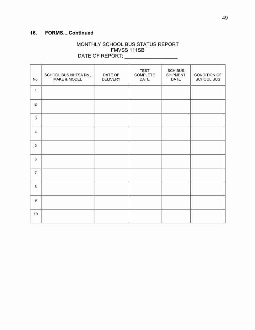
16. FORMS....Continued
MONTHLY SCHOOL BUS STATUS REPORT FMVSS 111SB
DATE OF REPORT: ___________________
No. SCHOOL BUS NHTSA No.,
MAKE & MODEL DATE OF
DELIVERY
TEST COMPLETE
DATE
SCH BUS SHIPMENT
DATE CONDITION OF SCHOOL BUS
1
2
3
4
5
6
7
8
9
10
50
APPENDIX 1 REFLECTANCE TEST - ALL MIRRORS
(1) REQUIREMENT (S11)
All single reflectance mirrors shall have an average reflectance of at least 35 percent. If a mirror is capable of multiple reflectance levels, the minimum reflectance level in the day mode shall be at least 35 percent and the minimum reflectance level in the night mode shall be at least 4 percent. The average reflectance of any mirror required by this standard shall be determined in accordance with SAE Recommended Practice J964, OCT 84.
A multiple reflectance mirror shall either be equipped with a means for the driver to adjust the mirror to a reflectance level of at least 35 percent in the event of electrical failure, or achieve such reflectance level automatically in the event of electrical failure.
(2) APPARATUS DESCRIPTION, SETUP, AND PREPARATION
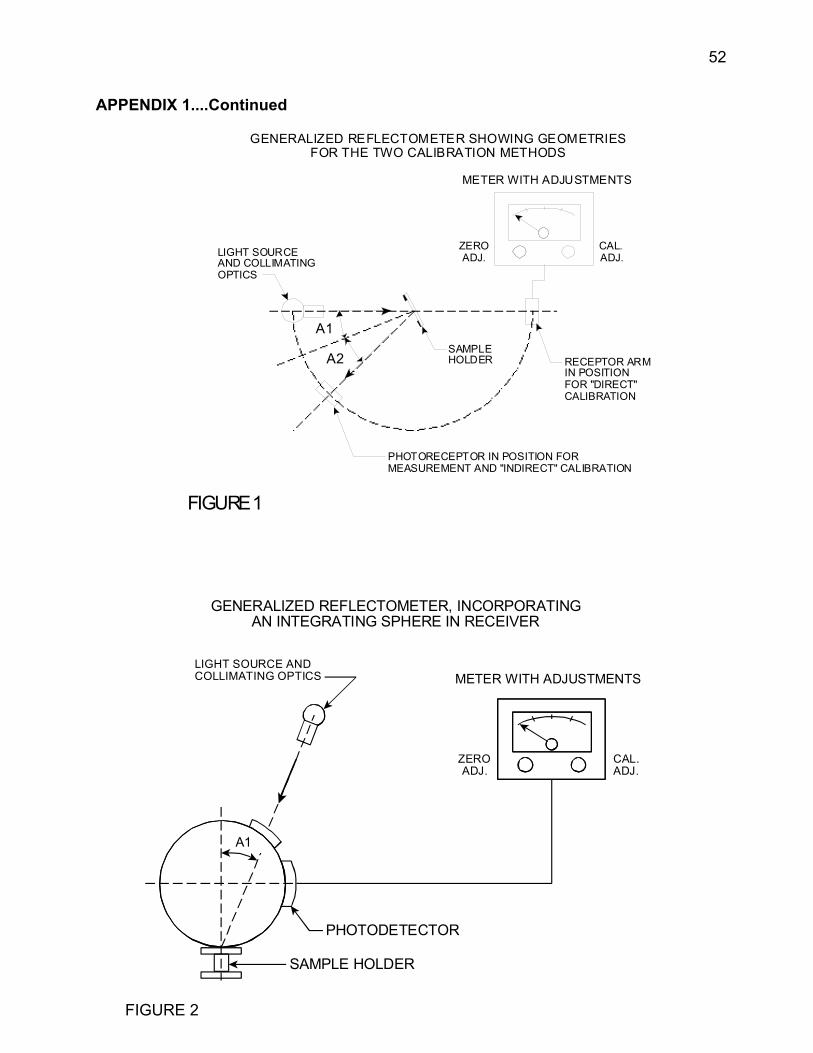
The apparatus shall consist of a light source, a sample holder, a receiver unit with a photodetector and an indicating meter as shown in Figure 1, and means for negating the effects of extraneous light. The receiver may incorporate a light integrating sphere to facilitate measuring reflectance of nonflat (convex) mirrors as shown in Figure 2.
(A) Characteristic of Light Source and Photoreceptor
The light source shall consist of an incandescent tungsten filament lamp operating at a nominal color temperature of 2,856 K (CIE Illuminant A) and associated optics to provide a near collimated light beam. A voltage stabilizer is recommended for maintaining a fixed lamp voltage during instrument operation. The photoelectric receptor shall have a spectral response proportional to the photopic luminosity function of the standard CIE observer. Any other combination of illuminant-filters-receptor which gives the overall equivalent of illuminant A and average visual response may be used.
When an integrating sphere is used in the receiver, the interior surface of the sphere shall be coated with a matt (diffusive) spectrally nonselective white coating.
51
APPENDIX 1....Continued
(B) Geometric Conditions
The angle of the incident beam (A1) shall preferably be 25� ± 5� (0.44 ± 0.09 radian) and shall not exceed 30� (0.53 radians) from the perpendicular to the test surface, and the axis of the receptor shall make an angle (A2) with this perpendicular equal to that of the incident beam. The incident beam upon arrival to the test surface, shall have a diameter of 19 mm (0.75 inch) or larger and shall not exceed the sample test area. The reflected beam upon arrival at the photoreceptor, shall not be larger than the photo-sensitive area and shall not cover less than 50 percent of such area. The reflected beam should strike that area of the photoreceptor used for calibration.
When an integrating sphere is used in the receiver section, the sphere shall have a minimum diameter of 127 mm (5 in). The sample and incident beam apertures in the sphere wall shall be of such a size as to admit the entire incident and reflected light beams. The photodetector shall be so located as not to receive direct light from either the incident or the reflected beams.
(C) Receptor-Indicator Unit
The photoreceptor output as read on the indicating meter shall be a linear function of the light intensity on the photosensitive area of the receptor. Further, means (electrical and/or optical) shall be provided for calibration and zeroing adjustments. Such means shall not affect the linearity or the spectral characteristics of the instrument. The accuracy of the receptor-indicator unit shall be within ± 2% of full scale, or ± 10% of the magnitude of the reading, whichever is smaller.
(D) Sample Holder
The mechanism shall be capable of locating the test sample such that the axes of the source arm and receptor arm intersect at the reflecting surface. The reflecting surface may lie within or at either face of the mirror sample depending on whether it is a first-surface, second-surface, or prismatic "flip" type mirror.
52
APPENDIX 1....Continued
GENERALIZED REFLECTOMETER SHOWING GEOMETRIES FOR THE TWO CALIBRATION METHODS
SAMPLE HOLDER
IN POSITION RECEPTOR AR M
FOR "DIRECT" CALIBRATION
PHOTORECEPTOR IN POSITION FOR MEASUREMENT AND "INDIRECT" CALIBRATION
FIGURE1
GENERALIZED REFLECTOMETER, INCORPORATING AN INTEGRATING SPHERE IN RECEIVER
LIGHT SOURCE AND
CAL. ADJ.
METER WITH ADJUSTMENTS
A1
PHOTODETECTOR
SAMPLE HOLDER
COLLIMATING OPTICS
ZERO ADJ.
METER WITH ADJUSTMENTS
ZERO CAL. ADJ. ADJ. LIGHT SOURCE
AND COLLIMATING OPTICS
A1
A2
FIGURE 2
53
APPENDIX 1....Continued
(E) Direct Calibration Method
The direct calibration method is for those instruments which are so constructed as to permit calibration at the 100% point by swinging the photoreceptor arm to a position directly on the axis of the light source.
It may be desired in some cases (such as, when measuring low reflective surfaces) to use an intermediate calibration point neutral density filter of known transmission value inserted in the optical path. The calibrate control will then be adjusted until the meter reads the percent transmission of the neutral density filter. This filter must be removed before making any reflectivity measurement.
(F) Indirect Calibration Method
The indirect calibration method is for those instruments with a fixed photoreceptor arm and thus requires a properly calibrated and maintained reference mirror standard.
(G) Flat Mirror Measurement
Reflectance of flat mirror samples is measured on instruments which employ either the direct or indirect calibration method. The reflectance value is read directly from the instrument indicator meter.
(H) Nonflat (Convex) Mirror Measurement
Reflectance of nonflat (convex) mirror measurement requires the use of instruments which incorporate an integrating sphere in the receiver unit. The reflectance value is read directly from the instrument indicating meter.
(3) REFLECTANCE TEST PROCEDURE
(A) Conduct test with mirror in the day mode.
(B) The mirror is mounted in a special holder.
(C) The photoreceptor is mounted such that light from the light source is directly received as shown in Figure 1.
54
APPENDIX 1....Continued
(D) Five measurements are made. After each measurement, the photoreceptor is moved and then realigned such that the meter reading is a maximum.
(E) The mirror in the sample holder is placed to receive the light beam as shown in Figure 1.
(F) The photoreceptor is located such that only light reflected from the mirror is received, normal to the photoreceptor surface.
(G) Five measurements are made, each time adjusting the photoreceptor to maximize the reading.
(H) The direct light readings are averaged.
(I) The reflected light readings are averaged.
(J) The percentage of light reflected is computed and the reflectance determined.
(K) All measurements will be recorded and calculations performed as called for on Data Sheet 6. An average reflectance value is calculated for each single reflectance mirror and for the daytime and nighttime modes of the inside rearview mirror (where applicable).
(L) Repeat test with the mirror in the night mode, if so equipped.
(M) If a multiple reflectance mirror remove all electrical power and adjust manually to day mode position, if so equipped. Repeat test for the day mode requirement. (For multiple reflectance mirrors obtain instructions from the COTR concerning the manufacturer's recommended procedure for obtaining "day mode" and "night mode" position settings.)
(N) Record results on Data Sheet 6.
55
APPENDIX 2 UNIT MAGNIFICATION AND CONVEX MIRROR TESTS -ALL MIRRORS
(1) SUGGESTED TEST EQUIPMENT
A 3-point linear spherometer with two outer fixed legs 1.5 inches apart and one inner movable leg at the mid-point. The spherometer should have a dial indicator with a scale that can be read accurately to 0.0001 inches, with the zero reading being a flat surface.
NOTE: English units are necessary to enable use of Table 1.
(2) RADIUS OF CURVATURE TEST PROCEDURE (S12.)
Steps (A) thru (F) apply to convex mirrors. Only steps (A) and (B) apply to unit magnification mirrors.
(A) Visually inspect mirror for any discontinuities.
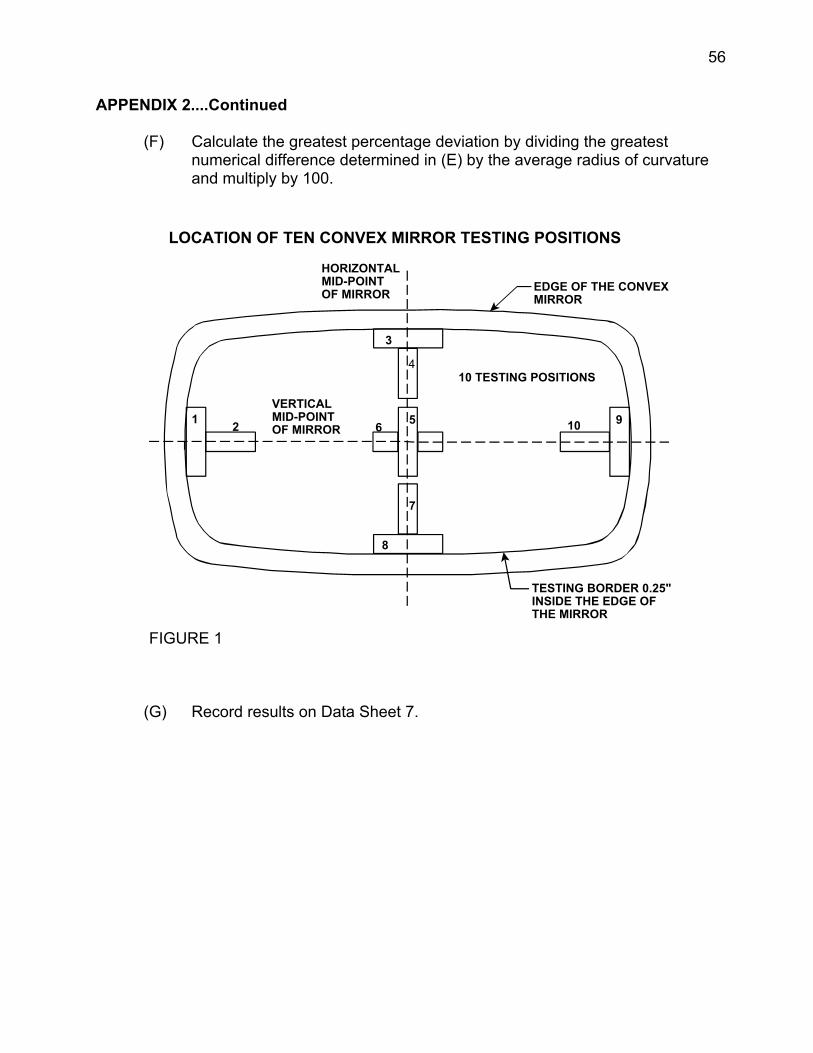
(B) Using a 3-point linear spherometer measure the radius of curvature at the 10 test points indicated in Figure 1. The 10 test positions consist of two positions at right angles to each other at each of five locations. The locations are at the center of the mirror, at the left and right ends of a horizontal line that bisects the mirror and at the top and bottom ends of a vertical line that bisects the mirror. None of the readings are within a 6.4 mm (0.25 inch) border on the edge of the image display. At each position, hold the spherometer perpendicular to the mirror surface and record the reading on the dial indicator to the nearest 0.0001 inch.
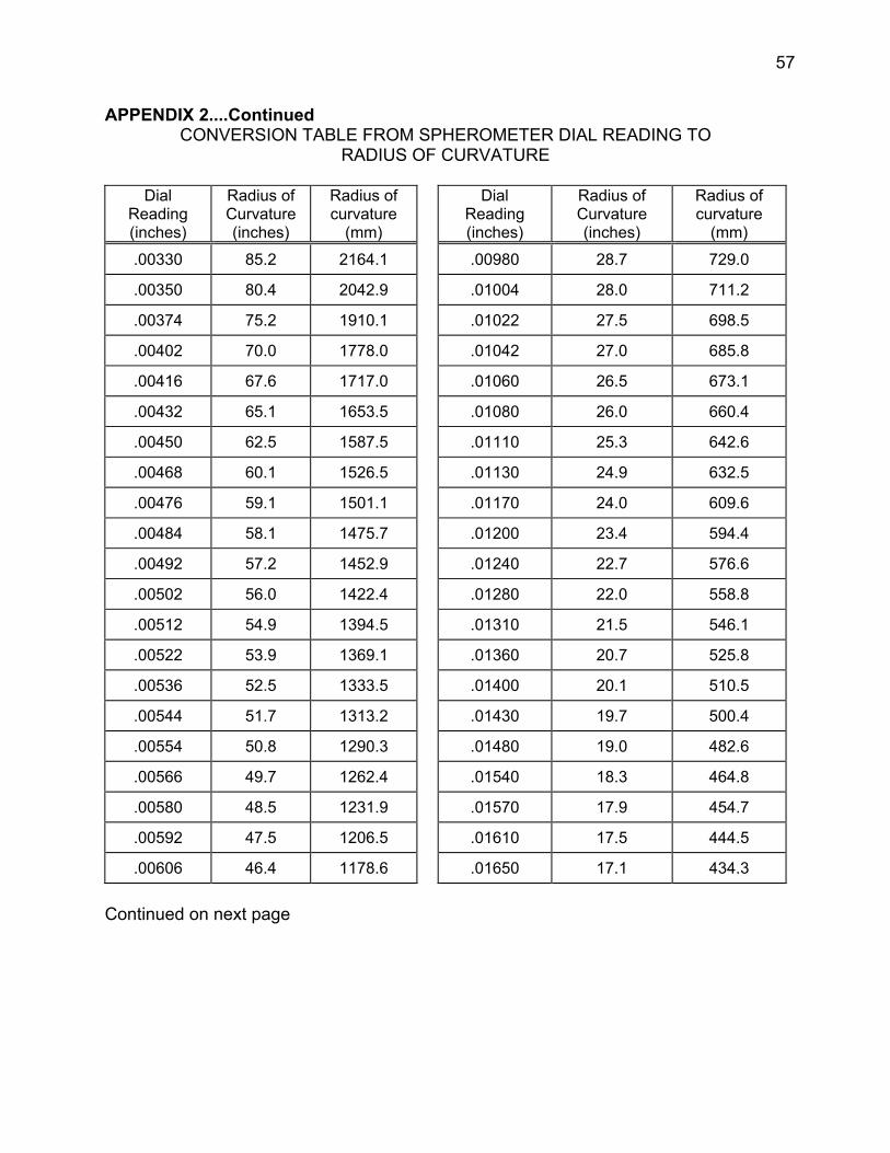
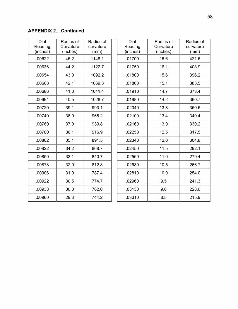
(C) Convert the dial reading data for each of the 10 test positions to radius of curvature measurements in millimeters using Table 1 of this procedure. Consider the changes as linear for dial readings that fall between two numbers in Table I. NOTE: If dial indicator is graduated in metric units, all the radius of curvature values in table 1 are invalid.
(D) Calculate the average radius of curvature by adding the 10 radius of curvature measurements and dividing by ten.
(E) Determine the numerical difference between the average radius of curvature and each of the 10 individual radius of curvature measurements in (C) above.
56
APPENDIX 2....Continued
(F) Calculate the greatest percentage deviation by dividing the greatest numerical difference determined in (E) by the average radius of curvature and multiply by 100.
(G) Record results on Data Sheet 7.
LOCATION OF TEN CONVEX MIRROR TESTING POSITIONS
EDGE OF THE CONVEXMIRROR
HORIZONTAL MID-POINT OF MIRROR
TESTING BORDER 0.25"INSIDE THE EDGE OF THE MIRROR
VERTICALMID-POINT OF MIRROR
10 TESTING POSITIONS
1 2
3
4
6 5
8
7
10 9
FIGURE 1
57
APPENDIX 2....Continued CONVERSION TABLE FROM SPHEROMETER DIAL READING TO
RADIUS OF CURVATURE
Dial Reading (inches)
Radius of Curvature (inches)
Radius of curvature
(mm) .00330
.00350
.00374
.00402
.00416
.00432
.00450
.00468
.00476
.00484
.00492
.00502
.00512
.00522
.00536
.00544
.00554
.00566
.00580
.00592
.00606
2164.1 85.2
2042.9 80.4
1910.1 75.2
1778.0 70.0
1717.0 67.6
1653.5 65.1
1587.5 62.5
1526.5 60.1
1501.1 59.1
1475.7 58.1
1452.9 57.2
1422.4 56.0
1394.5 54.9
1369.1 53.9
1333.5 52.5
1313.2 51.7
1290.3 50.8
1262.4 49.7
1231.9 48.5
1206.5 47.5
1178.6 46.4
Dial Reading (inches)
Radius of Curvature (inches)
Radius of curvature
(mm) .00980 28.7 729.0
.01004 28.0 711.2
.01022 27.5 698.5
.01042 27.0 685.8
.01060 26.5 673.1
.01080 26.0 660.4
.01110 25.3 642.6
.01130 24.9 632.5
.01170 24.0 609.6
.01200 23.4 594.4
.01240 22.7 576.6
.01280 22.0 558.8
.01310 21.5 546.1
.01360 20.7 525.8
.01400 20.1 510.5
.01430 19.7 500.4
.01480 19.0 482.6
.01540 18.3 464.8
.01570 17.9 454.7
.01610 17.5 444.5
.01650 17.1 434.3
Continued on next page
58
APPENDIX 2....Continued
Dial Reading (inches)
Radius of Curvature (inches)
Radius of curvature
(mm) .00622
.00636
.00654
.00668
.00686
.00694
.00720 993.1
.00740 965.2
.00760 939.8
.00780 916.9
.00802 891.5
.00822 868.7
.00850 840.7
.00878 812.8
.00906 787.4
.00922 774.7
.00938 762.0
.00960 744.2
1148.1 45.2
1122.7 44.2
1092.2 43.0
1069.3 42.1
1041.4 41.0
1028.7 40.5
39.1
38.0
37.0
36.1
35.1
34.2
33.1
32.0
31.0
30.5
30.0
29.3
Dial Reading (inches)
Radius of Curvature (inches)
Radius of curvature
(mm) .01700 16.6 421.6
.01750 16.1 408.9
.01800 15.6 396.2
.01860 15.1 383.5
.01910 14.7 373.4
.01980 14.2 360.7
.02040 13.8 350.5
.02100 13.4 340.4
.02160 13.0 330.2
.02250 12.5 317.5
.02340 12.0 304.8
.02450 11.5 292.1
.02560 11.0 279.4
.02680 10.5 266.7
.02810 10.0 254.0
.02960 9.5 241.3
.03130 9.0 228.6
.03310 8.5 215.9