laboratory test procedure for - nhtsa.gov safety/test procedures...tp-537-01 march 30, 2009 u.s....
TRANSCRIPT
TP-537-01
March 30, 2009 U.S. DEPARTMENT OF TRANSPORTATION NATIONAL HIGHWAY TRAFFIC SAFETY ADMINISTRATION LABORATORY TEST PROCEDURE FOR
49 CFR Part 537, AUTOMOTIVE FUEL ECONOMY ATTRIBUTE MEASUREMENTS
ENFORCEMENT Office of Vehicle Safety Compliance
Mail Code: NVS-220 1200 New Jersey Ave. SE Washington, DC 20590
OVSC LABORATORY TEST PROCEDURE NO. 537 TABLE OF CONTENTS
PAGE
1. PURPOSE AND APPLICATION ........................................................................... 1
2. GENERAL REQUIREMENTS ............................................................................... 2
3. SECURITY............................................................................................................ 3
4. GOOD HOUSEKEEPING ..................................................................................... 4
5. TEST SCHEDULING AND MONITORING............................................................ 4
6. TEST DATA DISPOSITION .................................................................................. 4
7. GOVERNMENT FURNISHED PROPERTY (GFP) ............................................... 6
8. CALIBRATION OF TEST INSTRUMENTS ........................................................... 8
9. SUGGESTED TEST EQUIPMENT ....................................................................... 9
10. PHOTOGRAPHIC DOCUMENTATION.............................................................. 12
11. DEFINITIONS..................................................................................................... 13
12. TEST VEHICLE IDENTIFICATION AND INSPECTION ..................................... 17
13. TEST EXECUTION ............................................................................................ 19
14. POST TEST REQUIREMENTS.......................................................................... 27
15. REPORTS .......................................................................................................... 27
15.1. MONTHLY STATUS REPORTS .............................................................. 27
15.2. APPARENT NON-CONFORMANCE ....................................................... 27
15.3. FINAL TEST REPORTS........................................................................... 27
15.3.1 COPIES........................................................................................ 27
15.3.2 REQUIREMENTS ......................................................................... 28
15.3.3 FIRST THREE PAGES ................................................................. 29
16. DATA SHEETS .................................................................................................. 35
17. FORMS .............................................................................................................. 41
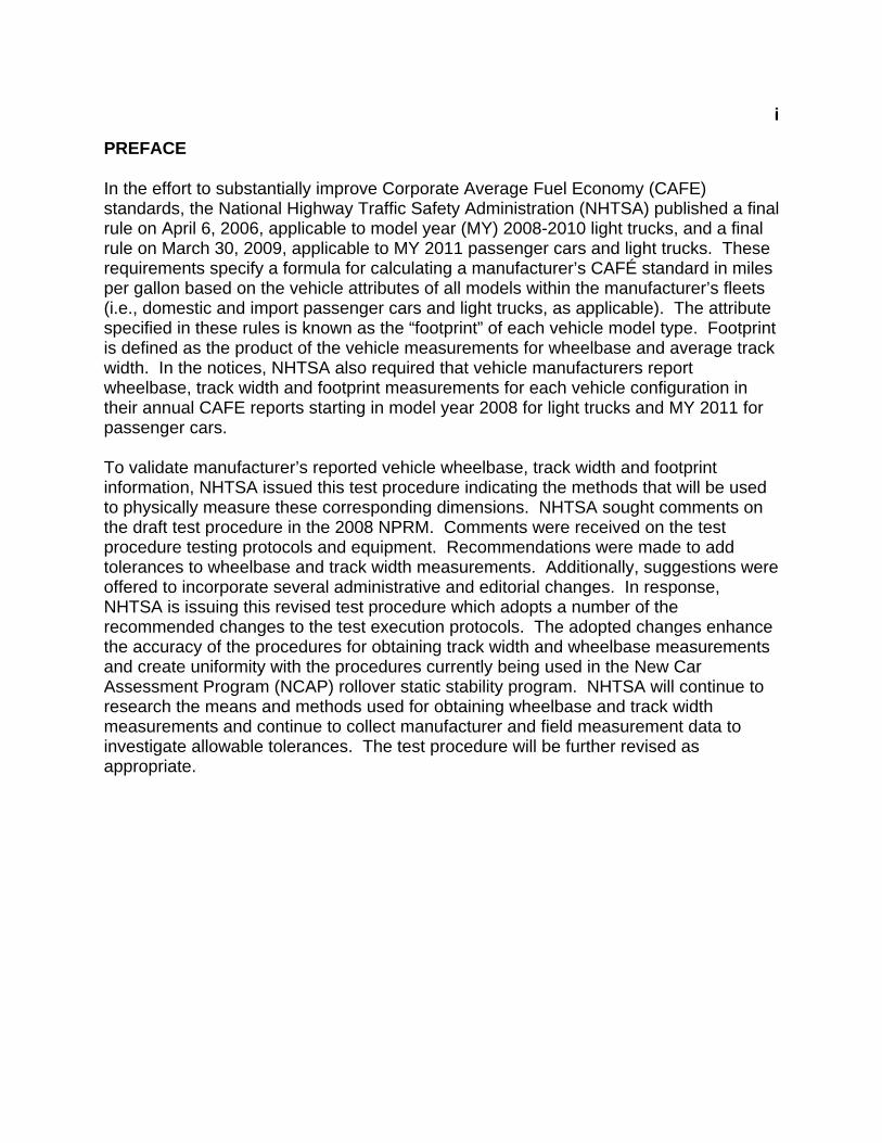
i PREFACE
In the effort to substantially improve Corporate Average Fuel Economy (CAFE) standards, the National Highway Traffic Safety Administration (NHTSA) published a final rule on April 6, 2006, applicable to model year (MY) 2008-2010 light trucks, and a final rule on March 30, 2009, applicable to MY 2011 passenger cars and light trucks. These requirements specify a formula for calculating a manufacturer’s CAFÉ standard in miles per gallon based on the vehicle attributes of all models within the manufacturer’s fleets (i.e., domestic and import passenger cars and light trucks, as applicable). The attribute specified in these rules is known as the “footprint” of each vehicle model type. Footprint is defined as the product of the vehicle measurements for wheelbase and average track width. In the notices, NHTSA also required that vehicle manufacturers report wheelbase, track width and footprint measurements for each vehicle configuration in their annual CAFE reports starting in model year 2008 for light trucks and MY 2011 for passenger cars.
To validate manufacturer’s reported vehicle wheelbase, track width and footprint information, NHTSA issued this test procedure indicating the methods that will be used to physically measure these corresponding dimensions. NHTSA sought comments on the draft test procedure in the 2008 NPRM. Comments were received on the test procedure testing protocols and equipment. Recommendations were made to add tolerances to wheelbase and track width measurements. Additionally, suggestions were offered to incorporate several administrative and editorial changes. In response, NHTSA is issuing this revised test procedure which adopts a number of the recommended changes to the test execution protocols. The adopted changes enhance the accuracy of the procedures for obtaining track width and wheelbase measurements and create uniformity with the procedures currently being used in the New Car Assessment Program (NCAP) rollover static stability program. NHTSA will continue to research the means and methods used for obtaining wheelbase and track width measurements and continue to collect manufacturer and field measurement data to investigate allowable tolerances. The test procedure will be further revised as appropriate.
ii
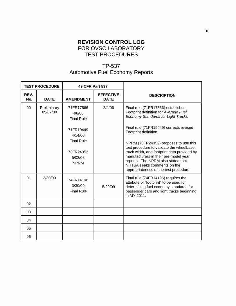
REVISION CONTROL LOG FOR OVSC LABORATORY
TEST PROCEDURES
TP-537 Automotive Fuel Economy Reports
TEST PROCEDURE
49 CFR Part 537
REV. No.
DATE
AMENDMENT
EFFECTIVE
DATE
DESCRIPTION
00
Preliminary 05/02/08
71FR17566
4/6/06 Final Rule
71FR19449
4/14/06 Final Rule
73FR24352
5/02/08 NPRM
8/4/06
Final rule (71FR17566) establishes Footprint definition for Average Fuel Economy Standards for Light Trucks Final rule (71FR19449) corrects revised Footprint definition. NPRM (73FR24352) proposes to use this test procedure to validate the wheelbase, track width, and footprint data provided by manufacturers in their pre-model year reports. The NPRM also stated that NHTSA seeks comments on the appropriateness of the test procedure.
01
3/30/09 74FR14196
3/30/09 Final Rule
5/29/09
Final rule (74FR14196) requires the attribute of “footprint” to be used for determining fuel economy standards for passenger cars and light trucks beginning in MY 2011.
02
03
04
05
06
1. PURPOSE AND APPLICATION This document is a laboratory test procedure provided by the National Highway Traffic Safety Administration (NHTSA), Office of Vehicle Safety Compliance (OVSC) for the purpose of presenting guidelines for a uniform testing data and information recording format, and providing suggestions for the use of specific equipment and procedures for contracted testing laboratories. The data correspond to specific requirements of a Federal Motor Vehicle Safety Standard or a Federal regulation (hereafter FMVSS or regulation). The OVSC test procedures include requirements that are general in scope to provide flexibility for contracted laboratories to perform compliance testing and are not intended to limit or restrain a contractor from developing or utilizing any testing techniques or equipment which will assist in procuring the required compliance test data. These test procedures do not constitute an endorsement or recommendation for use of any particular product or testing method. Prior to conducting compliance testing, contracted laboratories are required to submit a detailed test procedure to the Contracting Officer's Technical Representative (COTR) to demonstrate concurrence with the OVSC laboratory test procedure and the applicable FMVSS or regulation. If any contractor views any part of an OVSC laboratory test procedure to be in conflict with a FMVSS or regulation or observes deficiencies in a laboratory test procedure, the contractor is required to advise the COTR and resolve the discrepancy prior to the start of compliance testing or as soon as practicable. The contractor’s test procedure must include a step-by-step description of the methodology and detailed check-off sheets. Detailed check-off sheets shall also be provided for the testing instrumentation including a complete listing of the test equipment with make and model numbers. The list of test equipment shall include instrument accuracy and calibration dates. All equipment shall be calibrated in accordance with the manufacturer’s instructions. There shall be no contradictions between the laboratory test procedure and the contractor’s in-house test procedure. Written approval of the in-house test procedures shall be obtained from the COTR before initiating the compliance test program. NOTE: The OVSC Laboratory Test Procedures, prepared for the limited purpose of use by independent laboratories under contract to conduct compliance tests for the OVSC, are not rules, regulations or NHTSA interpretations regarding the meaning of a FMVSS or regulation. The laboratory test procedures are not intended to limit the requirements of the applicable FMVSS(s) or regulations. In some cases, the OVSC laboratory test procedures do not include all of the various minimum performance requirements of a FMVSS or regulation. Recognizing applicable test tolerances, the laboratory test procedures may specify test conditions that are less severe than the minimum requirements of the FMVSS or regulation. In addition, the laboratory test procedures may be modified by the OVSC at any time without notice, and the COTR may direct or authorize contractors to deviate from these procedures, as long as the tests are performed in a manner consistent with the FMVSS or regulation itself and within the scope of the contract. Laboratory test procedures may not be relied upon to create any right or benefit in any person. Therefore, compliance of a vehicle or item of motor vehicle equipment is not necessarily guaranteed if the manufacturer limits its certification tests to those described in the OVSC laboratory test procedures.
22. GENERAL REQUIREMENTS
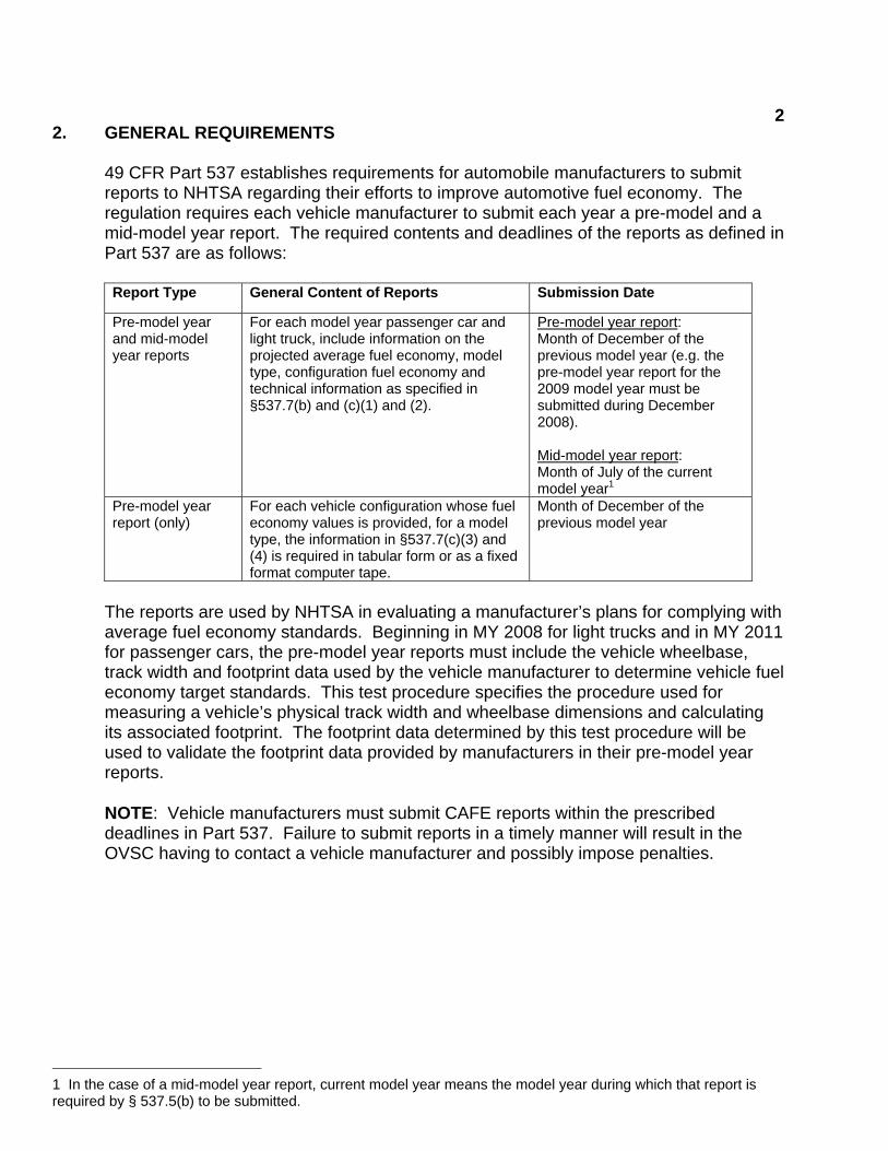
49 CFR Part 537 establishes requirements for automobile manufacturers to submit reports to NHTSA regarding their efforts to improve automotive fuel economy. The regulation requires each vehicle manufacturer to submit each year a pre-model and a mid-model year report. The required contents and deadlines of the reports as defined in Part 537 are as follows: Report Type General Content of Reports Submission Date
Pre-model year and mid-model year reports
For each model year passenger car and light truck, include information on the projected average fuel economy, model type, configuration fuel economy and technical information as specified in §537.7(b) and (c)(1) and (2).
Pre-model year report: Month of December of the previous model year (e.g. the pre-model year report for the 2009 model year must be submitted during December 2008). Mid-model year report: Month of July of the current model year1
Pre-model year report (only)
For each vehicle configuration whose fuel economy values is provided, for a model type, the information in §537.7(c)(3) and (4) is required in tabular form or as a fixed format computer tape.
Month of December of the previous model year
The reports are used by NHTSA in evaluating a manufacturer’s plans for complying with average fuel economy standards. Beginning in MY 2008 for light trucks and in MY 2011 for passenger cars, the pre-model year reports must include the vehicle wheelbase, track width and footprint data used by the vehicle manufacturer to determine vehicle fuel economy target standards. This test procedure specifies the procedure used for measuring a vehicle’s physical track width and wheelbase dimensions and calculating its associated footprint. The footprint data determined by this test procedure will be used to validate the footprint data provided by manufacturers in their pre-model year reports. NOTE: Vehicle manufacturers must submit CAFE reports within the prescribed deadlines in Part 537. Failure to submit reports in a timely manner will result in the OVSC having to contact a vehicle manufacturer and possibly impose penalties.
1 In the case of a mid-model year report, current model year means the model year during which that report is required by § 537.5(b) to be submitted.
32. GENERAL REQUIREMENTS….Continued
METRIC SYSTEM OF MEASUREMENT Section 5164 of the Omnibus Trade and Competitiveness Act (Pub. L. 100-418) establishes that the metric system of measurement is the preferred system of weights and measures for trade and commerce in the United States. Executive order 12770 directs Federal agencies to comply with the Act by converting regulatory standards to the metric system after September 30, 1992. In a final rule published on March 15, 1990 (60 FR 13639), NHTSA completed the first phase of metrication, converting English measurements in several regulatory standards to the metric system. Since then, metrication has been applied to other regulatory standards (63 FR 28912).
Accordingly, the OVSC laboratory test procedures include revisions to comply with governmental directives in using the metric system. Regulatory standards converted to metric units are required to use metric measurements in the test procedures, whereas standards using English units are allowed to use English measurements or to use English measurements in combination with metric equivalents in parentheses. For any testing equipment that is not available for direct measurement in metric units, the test laboratory shall calculate the exact metric equivalent by means of a conversion factor carried out to at least five significant digits before rounding consistent with the specified metric requirement. All final compliance test reports are required to include metric measurements for standards using metrication.
NOTE: The methodology for rounding measurement in the test reports shall be made in accordance with ASTM E29-06b, “Standard Practice for Using Significant Digits in Test Data to Determine Conformance with Specifications.”
3. SECURITY
The contractor shall provide appropriate security measures to protect the OVSC test vehicles and Government Furnished Property (GFP) from unauthorized personnel during the entire compliance testing program. The contractor is financially responsible for any acts of theft and/or vandalism which occur during the storage of test vehicles and GFP. Any security problems which arise shall be reported by telephone to the Industrial Property Manager (IPM), Office of Acquisition Management, within two working days after the incident. A letter containing specific details of the security problem shall be sent to the IPM (with copy to the COTR) within 48 hours.

43. SECURITY….Continued
The contractor shall protect and segregate the data that evolves from compliance testing before and after each vehicle test. No information concerning the vehicle safety compliance testing program shall be released to anyone except the COTR, unless specifically authorized by the COTR or the COTR's Division Chief.
NOTE: No individuals, other than contractor personnel directly involved in the compliance testing program or OVSC personnel, shall be allowed to witness any vehicle or equipment item compliance test unless specifically authorized by the COTR.
4. GOOD HOUSEKEEPING
Contractors shall maintain the entire vehicle compliance testing area, test fixtures and instrumentation in a neat, clean and painted condition with test instruments arranged in an orderly manner consistent with good test laboratory housekeeping practices.
5. TEST SCHEDULING AND MONITORING
The contractor shall submit a test schedule to the COTR prior to conducting the first compliance test. Tests shall be completed at intervals as required in the contract. If not specified, the first test shall be conducted within 6 weeks after receiving the first delivered unit. Subsequent tests shall be completed in no longer that 1 week intervals unless otherwise specified by the COTR. Scheduling of tests shall be adjusted to permit vehicles (or equipment, whichever applies) to be tested to other FMVSSs as may be required by the OVSC. All compliance testing shall be coordinated with the COTR in order to allow monitoring by the COTR and/or other OVSC personnel if desired. The contractor shall submit a monthly test status report and a vehicle status report (if applicable) to the COTR. The vehicle status report shall be submitted until all vehicles are disposed of. The status report forms are provided in the forms section.
6. TEST DATA DISPOSITION
The Contractor shall make all preliminary compliance test data available to the COTR on location within four hours after completing all testing. Final test data, including digital printouts and computer generated plots (if applicable), shall be available to the COTR in accordance with the contract schedule or if not specified within two working days. Additionally, the Contractor shall analyze the preliminary test results as directed by the COTR.
56. TEST DATA DISPOSITION….Continued
All backup data sheets, strip charts, recordings, plots, technicians’ notes, etc., shall be either sent to the COTR or destroyed at the conclusion of each delivery order, purchase order, etc.
The contractor shall protect and segregate the data that evolves from compliance testing before and after each test.
TEST DATA LOSS
A. INVALID TEST DESCRIPTION
An invalid compliance test is one, which does not conform precisely to all requirements/specifications of the OVSC Laboratory Test Procedure and Statement of Work applicable to the test.
B. INVALID TEST NOTIFICATION
The Contractor shall notify NHTSA of any test not meeting all requirements/specifications of the OVSC Laboratory Test Procedure and Statement of Work applicable to the test, by telephone, within 24 hours of the test and send written notice to the COTR within 48 hours or the test completion.
C. RETEST NOTIFICATION
The Contracting Officer of NHTSA is the only NHTSA official authorized to notify the Contractor that a retest is required. The retest shall be completed within 2 weeks after receipt of notification by the Contracting Officer that a retest is required.
D. WAIVER OF RETEST
NHTSA, in its sole discretion, reserves the right to waive the retest requirement. This provision shall not constitute a basis for dispute over the NHTSA's waiving or not waiving any requirement. E. TEST VEHICLE
NHTSA shall furnish only one vehicle for each test ordered. The Contractor shall furnish the test vehicle required for the retest. The retest vehicle shall be equipped as the original vehicle. The original vehicle used in the invalid test shall remain the property of NHTSA, and the retest vehicle shall remain the property of the Contractor. The Contractor shall retain the retest vehicle for a period not exceeding 180 days if it fails the test. If the retest vehicle passes the test, the Contractor may dispose of it upon
66. TEST DATA DISPOSITION….Continued
notification from the COTR that the test report has been accepted.
F. TEST REPORT
No test report is required for any test that is determined to be invalid unless NHTSA specifically decides, in writing, to require the Contractor to submit such report. The test data from the invalid test must be safeguarded until the data from the retest has been accepted by the COTR. The electronic data, draft final test report and video shall be submitted within 14 days of the final test. The final test report, dummy calibration report, and video shall be submitted 7 days after receiving comments from the COTR.
G. DEFAULT
The Contractor is subject to the default and subsequent reprocurement costs for nondelivery of valid or conforming test (pursuant to the “Termination for Default” clause in the contract).
H. NHTSA'S RIGHTS
None of the requirements herein stated shall diminish or modify the rights of NHTSA to determine that any test submitted by the Contractor does not conform precisely to all requirements/specifications of the OVSC Laboratory Test Procedure and Statement of Work applicable to the test.
7. GOVERNMENT FURNISHED PROPERTY (GFP)
GFP consist of test vehicles and may include testing equipment. The GFP is authorized by contractual agreement. The contractor is responsible for the following. A. ACCEPTANCE OF TEST VEHICLES The contractor has the responsibility of accepting each GFP test vehicle whether delivered by a new vehicle dealership or another vehicle transporter. In both instances, the Contractor acts on behalf of the OVSC when signing an acceptance of the GFP test vehicle delivery order. When a GFP vehicle is delivered, the contractor must verify:
1. All options listed on the "window sticker" are present on the test vehicle. 2. Tires and wheel rims are new and the same as listed.

77. GOVERNMENT FURNISHED PROPERTY (GFP)….Continued
3. There are no dents or other interior or exterior flaws in the vehicle body. 4. The vehicle has been properly prepared and is in running condition. 5. The glove box contains an owner's manual, warranty document, consumer
information, and extra set of keys. 6. Proper fuel filler cap is supplied on the test vehicle. 7. Spare tire, jack, lug wrench and tool kit (if applicable) are located in the vehicle
cargo area.
8. The VIN (vehicle identification number) on the vehicle condition report matches the VIN on the vehicle.
9. The vehicle is equipped as specified by the COTR.
A Vehicle Condition form will be supplied to the Contractor by the COTR when the test vehicle is transferred from a new vehicle dealership or between test contracts. The upper half of the form is used to describe the vehicle as initially accepted. The lower half of the Vehicle Condition form provides space for a detailed description of the post-test condition. The contractor must complete a Vehicle Condition form for each vehicle and deliver it to the COTR with the Final Test Report or the report will NOT be accepted for payment. If the test vehicle is delivered by a government contracted transporter, the contractor should check for damage which may have occurred during transit. GFP vehicle(s) shall not be driven by the contractor on public roadways unless authorized by the COTR. B. TESTING EQUIPMENT Test equipment may be furnished to the contracted laboratory by the OVSC. Otherwise, the contracted laboratory will be responsible for obtaining the test equipment required to execute this test. C. NOTIFICATION OF COTR
The COTR must be notified within 24 hours after a vehicle (and/or equipment) has been delivered. In addition, if any discrepancy or damage is found at the time of delivery, a copy of the Vehicle Condition form shall be sent to the COTR immediately.
88. CALIBRATION OF TEST INSTRUMENTS
Before the Contractor initiates the vehicle safety compliance test program, a test instrumentation calibration system must be implemented and maintained in accordance with established calibration practices. The calibration system shall include the following as a minimum:
A. Standards for calibrating the measuring and test equipment shall be stored and
used under appropriate environmental conditions to assure their accuracy and stability.
B. All measuring instruments and standards shall be calibrated by the Contractor, or
a commercial facility, against a higher order standard at periodic intervals not exceeding 12 months for instruments and 12 months for the calibration standards except for static types of measuring devices such as rulers, weights, etc., which shall be calibrated at periodic intervals not to exceed two years. Records, showing the calibration traceability to the National Institute of Standards and Technology (NIST), shall be maintained for all measuring and test equipment.
C. All measuring and test equipment and measuring standards shall be labeled with
the following information:
1. Date of calibration
2. Date of next scheduled calibration
3. Name of the technician who calibrated the equipment
D. A written calibration procedure shall be provided by the Contractor, which includes as a minimum the following information for all measurement and test equipment:
1. Type of equipment, manufacturer, model number, etc.
2. Measurement range
3. Accuracy
4. Calibration interval
5. Type of standard used to calibrate the equipment (calibration traceability
of the standard must be evident)
6. The actual procedures and forms used to perform the calibrations.

98. CALIBRATION AND TEST INSTRUMENTATION….Continued
E. Records of calibration for all test instrumentation shall be kept by the Contractor
in a manner that assures the maintenance of established calibration schedules. F. All such records shall be readily available for inspection when requested by the
COTR. The calibration system shall need the acceptance of the COTR before vehicle safety compliance testing commences.
G. Test equipment shall receive a system functional check out using a known test
input immediately before and after the test. This check shall be recorded by the test technician(s) and submitted with the final report.
Further guidance is provided in the International Standard ISO 10012-1, “Quality Assurance Requirements for Measuring Equipment” and American National Standard ANSI/NCSL Z540-1, “Calibration Laboratories and Measuring and Test Equipment General Requirements.” NOTE: In the event of a failure to meet the standard's minimum performance requirements additional calibration checks of some critically sensitive test equipment and instrumentation may be required for verification of accuracy. The necessity for the calibration will be at the COTR's discretion and shall be performed without additional cost.
9. SUGGESTED TEST EQUIPMENT
A. Steel Tape Measure 7,620 mm (300 inches) with 1 mm graduated increments (i.e., Tajima Tool Corp standard/metric shock resistant tape measure, Model No. G-25/7.5MBW);
B. Straight Aluminum Edge Ruler, 3,658 mm x 51 mm (144 inches x 2 inches), with 1 mm and 1/10 inch graduated increments (i.e., Fairgate, Model No. FAI-20-144me);
C. Laser Distance Meter with a measuring range of at least 15.24 meters (50ft),
resolution of 1 mm and an accuracy of 1.5 mm (i.e., Fluke, Model No. 416D); D. Digital Inclinometer with range of 0 - 360°, a resolution of 0.1o, and an accuracy
of + 0.2° (i.e., Digital Protractor Angle Finder, Model Pro 360); E. Portable Tire Pressure Gage with bleeder valve and an operating pressure of 0-
700 kPa (0-100 psi), accuracy of + 0.5% of applied pressure, and graduated increments of 1 kPa (0.1 psi) (i.e., Intercomp Digital Tire Pressure Gage, Model Digital Air);

109. SUGGESTED TEST EQUIPMENT….Continued
F. Portable rechargeable air compressor;
G. 406 mm x 610 mm (16 inches x 24 inches) right angle ruler (i.e., Johnson Aluminum Rafter Square, Model No. CS5);
H. White correction marker (i.e., Liquid Paper, Click Correct), and
I. Two Tire Edge Determination Tools (TEDTs).
The TEDTs consist of two 762 mm (30 inches) I-beams identical in design and fabricated to the dimensions shown in Figure 1. Each TEDT has a 406 mm (16 inches) long by 25 mm (1 inch) deep cut-out along the bottom flange. The cut-out is required to ensure that the bottom flange does not make contact with the tire bulge at the ground thus allowing the upper flange to make flush contact against each tire sidewall. By contacting the tire sidewalls in this manner, the TEDT is able to define a longitudinal line on the inside or outside lower sidewall of the tire approximately 100 mm (4 inches) above the test floor and is orientated parallel to the longitudinal centerline of the tire.

119. SUGGESTED TEST EQUIPMENT….Continued
BOTTOM FLANGE CUT-OUT
30.0+.1
1.0+.
16.0+.7.0+.1
4.0+.
.35+.1 (TOOL
.25+.
4.0+.
TOP VIEW
SIDE VIEW FRONT/BACK VIEW
FIGURE 1 ‐ TIRE EDGE DETERMINATION TOOL DIMENSIONS REPRESENTED IN INCHES MATERIALS: ASTM A‐36 STEEL OR 6061‐T6 AMERICAN STANDARD ALUMINUM
1. 4 TOOL EDGES ARE MACHINED SQUARE AND PARALLEL 2. BOTTOM FLANGE SURFACE MACHINED FLAT 3. TOOL FACES ARE MACHINED FLAT
ORTHOGONAL VIEW
TOOL FACES
BOTTOM FLANGE SURFACE
1210. PHOTOGRAPHIC DOCUMENTATION Digital Photographs
The contractor shall take digital photographs of the test execution procedures. Photographs shall be taken in color and contain clear images. A tag, label or placard identifying the test item, NHTSA number (if applicable) and date shall appear in each photograph and must be legible. Each photograph shall be labeled as to the subject matter. The required resolution for digital photographs is a minimum of 1,600 x 1,200 pixels. Digital photographs are required to be created in color and in a JPG format. Glare or light from any illuminated or reflective surface should be minimized while taking photographs. The test reports should include enough photographs to describe the testing in detail and should be organized in a logical succession of consecutive pictures. The digital photographs should be included in the test report as 8 x 10 or 8½ x 11 inch (203 mm x 254 mm or 215.9 mm x 279 mm pictures). All photographs are required to be included in the test report in the event of a potential non-conformance. Any non-conformance must be photographed at various angles to assure complete coverage. Upon request, the photographs should be sent to the COTR on a CD or DVD and saved in a “read only” format to ensure that the digital photographs are the exact pictures taken during testing and have not been altered from the original condition.
Photographic Views
As a minimum the following test photographs shall be included in each vehicle final test report, submitted by the contractor: A. ¾ front view from left side of vehicle including the tires in contact with the ground
B. Close-up view of the tire tread patterns
C. Vehicle Certification Label
D. Vehicle Placard (titled, “Tire and Loading Information”)
E. Tire Inflation Pressure Label (optional label if provided)
F. Vehicle Window Sticker (Monroney label)
G. The TEDTs positioned while measuring the front and rear track widths
H. The testing equipment positioned while measuring the left or right side
wheelbases (both sides should be photographed if the vehicle is non-
symmetrical)
1311. DEFINITIONS
BASE TIRE(s) Base tire means the tire specified as standard equipment by a manufacturer on each vehicle configuration of a model type. NOTE: Vehicles with different tire sizes on each axle can have more than one base tire size. BASIC ENGINE2 Basic engine means a unique combination of manufacturer, engine displacement, number of cylinders, fuel system (e.g., type of fuel injection), catalyst usage, and other engine and emission control system characteristics specified by the Administrator. For electric vehicles, basic engine means a unique combination of manufacturer and electric traction motor, motor controller, battery configuration, electrical charging system, energy storage device, and other components. CAMBER ANGLE Camber angle is the angular displacement made between the vertical axis of the wheel and the vertical axis of the vehicle when viewed from the front or rear. If the top of the wheel is farther out than the bottom (that is, away from the axle), it is called positive camber; if the bottom of the wheel is farther out than the top, it is called negative camber (see Figure 2). CAR LINE2 Car line means a name denoting a group of vehicles within a make or car division which has a degree of commonality in construction (e.g., body, chassis). Car line does not consider any level of decor or opulence and is not generally distinguished by characteristics as roof line, number of doors, seats, or windows, except for station wagons or light-duty trucks. Station wagons and light-duty trucks are considered to be different car lines than passenger cars. FOOTPRINT The product of the average track width (measured in inches and rounded to the nearest tenth of an inch) times the wheelbase (measured in inches and rounded to the nearest tenth of an inch) divided by 144 and then rounded to the nearest tenth of a square foot. GROSS VEHICLE WEIGHT RATING (GVWR)2 Gross vehicle weight rating means the manufacturer's gross weight rating for the individual vehicle.
2 See 40 CFR. § 600.002-08 Definitions
1411. DEFINITIONS….Continued
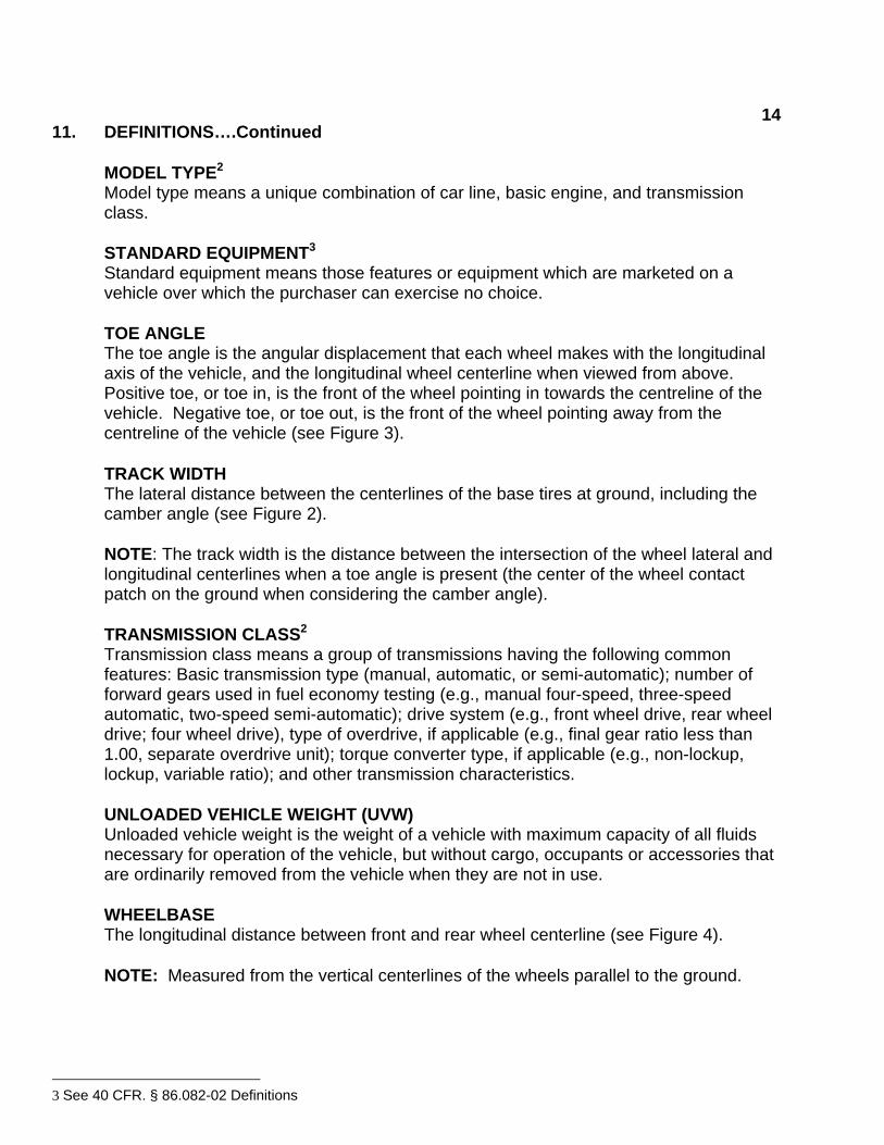
MODEL TYPE2 Model type means a unique combination of car line, basic engine, and transmission class.
STANDARD EQUIPMENT3 Standard equipment means those features or equipment which are marketed on a vehicle over which the purchaser can exercise no choice.
TOE ANGLE The toe angle is the angular displacement that each wheel makes with the longitudinal axis of the vehicle, and the longitudinal wheel centerline when viewed from above. Positive toe, or toe in, is the front of the wheel pointing in towards the centreline of the vehicle. Negative toe, or toe out, is the front of the wheel pointing away from the centreline of the vehicle (see Figure 3). TRACK WIDTH The lateral distance between the centerlines of the base tires at ground, including the camber angle (see Figure 2). NOTE: The track width is the distance between the intersection of the wheel lateral and longitudinal centerlines when a toe angle is present (the center of the wheel contact patch on the ground when considering the camber angle). TRANSMISSION CLASS2 Transmission class means a group of transmissions having the following common features: Basic transmission type (manual, automatic, or semi-automatic); number of forward gears used in fuel economy testing (e.g., manual four-speed, three-speed automatic, two-speed semi-automatic); drive system (e.g., front wheel drive, rear wheel drive; four wheel drive), type of overdrive, if applicable (e.g., final gear ratio less than 1.00, separate overdrive unit); torque converter type, if applicable (e.g., non-lockup, lockup, variable ratio); and other transmission characteristics. UNLOADED VEHICLE WEIGHT (UVW) Unloaded vehicle weight is the weight of a vehicle with maximum capacity of all fluids necessary for operation of the vehicle, but without cargo, occupants or accessories that are ordinarily removed from the vehicle when they are not in use. WHEELBASE The longitudinal distance between front and rear wheel centerline (see Figure 4). NOTE: Measured from the vertical centerlines of the wheels parallel to the ground.
3 See 40 CFR. § 86.082-02 Definitions
1511. DEFINITIONS….Continued
VEHICLE CONFIGURATION2 Vehicle configuration means a unique combination of basic engine, engine code, inertia weight class, transmission configuration, and axle ratio within a base level. VEHICLE PLACARD AND OPTIONAL TIRE INFLATION PRESSURE LABEL The sources of cold tire inflation pressure recommended by the vehicle manufacturer and provided in the location and format per Federal motor vehicle safety standard (FMVSS) No. 110.
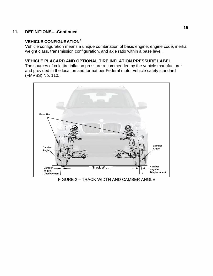
FIGURE 2 – TRACK WIDTH AND CAMBER ANGLE
Camber Angle
Camber Angle
Track Width
Base Tire
Camber angular Displacement
Camber angular Displacement
1611. DEFINITIONS….Continued
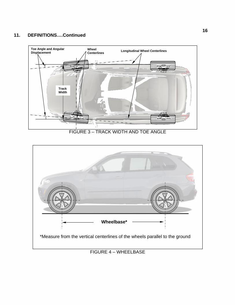
FIGURE 3 – TRACK WIDTH AND TOE ANGLE
FIGURE 4 – WHEELBASE
Wheelbase*
*Measure from the vertical centerlines of the wheels parallel to the ground
Toe Angle and Angular Displacement
Track Width
Wheel Centerlines Longitudinal Wheel Centerlines
1712. TEST VEHICLE IDENTIFICATION AND INSPECTION (DATA SHEET 1) 12.1 TESTING AT NEW VEHICLE DEALERSHIPS (Vehicle Selection Occurs On-Site)
A. Verify COTR’s approval of test procedure (if any) B. Review all test preparation, regulation definitions and specifications, and test
instrumentation requirements relating to this compliance test. Personnel supervising and/or performing the compliance test program shall be thoroughly familiar with the requirements, test conditions, and equipment for the test to be conducted.
C. Obtain and review the most current manufacturer’s pre-model year reports.
D. Develop a list of potential test vehicles. Vehicles shall be selected randomly or
selected based upon the risk criteria defined in the report, “OVSC Annual Selection Process for Compliance Test Program.” Make note of the corresponding vehicle manufacturers.
E. Arrange to visit new vehicle dealerships that have the vehicles identified above.
F. At each dealership, survey vehicles of interest and identify vehicles listed in the
manufacturer’s pre-model year reports on the basis of basic engine, transmission class and base tire size(s).
G. Only proceed to test those vehicles found on the dealer lot that are equipped with
the exact same basic engine, transmission class and base tires as identified in the manufacturers pre-model year reports.
H. For selected vehicles, ensure that all the vehicle tires are new. Each vehicle
must also be tested with the tires installed on the vehicle as specified on the vehicle’s Placard, optional Tire Inflation Pressure Label and the Monroney Label. The vehicle should not be tested if any tire installed on the vehicle is different from the manufacturer’s designated tire size obtained from the Vehicle Placard, optional Tire Inflation Pressure Label or Monroney Label.
I. For selected test vehicles, record the manufacturer’s pre-model year report
information and the relevant vehicle identification information.
1812. TEST VEHICLE INSPECTION AND TEST PREPARATION…Continued 12.2 TESTING AT CONTRACTED TEST LABORATORIES (With NHTSA Procured Vehicles)
A. Verify COTR approval of contractor’s detailed in-house test procedure.
B. Review all test preparation, regulation definitions and specifications, and test instrumentation requirements relating to this compliance test. Personnel supervising and/or performing the compliance test program shall be thoroughly familiar with the requirements, test conditions, and equipment for the test to be conducted.
C. Contracted laboratories must submit to the COTR a list of the NHTSA procured
test vehicles received. For each test vehicle note the make, model, engine, transmission, and installed tire size(s).
D. The COTR will review the list and compare it to the manufacturer’s submitted
pre-model year reports and identify which vehicles are equipped with the exact engine, transmission and base tire size combinations.
E. Vehicles found to have the exact engine, transmission and base tire size
combinations will be selected for testing.
F. For each NHTSA procured test vehicle identified by the COTR for testing, the relevant data from the manufacturer’s pre-model year report will be submitted to the contracted laboratory.
G. For selected vehicles, ensure that all the vehicle tires are new. Each vehicle
must also be tested with the tires installed on the vehicle as specified on the vehicle’s Placard, optional Tire Inflation Pressure Label and the Monroney Label. The vehicle should not be tested if any tire installed on the vehicle is different from the manufacturer’s designated tire size obtained from the Vehicle Placard, optional Tire Inflation Pressure Label or Monroney Label.
H. For selected test vehicles, record the manufacturer’s pre-model year report
information and the relevant vehicle identification information.
1913. TEST EXECUTION
Testing will be accomplished as indicated in sections 13.1 through 13.5. Test personnel shall make note of all discrepancies and deviations from the applicable regulation and this Laboratory Test Procedure.
13.1 TEST VEHICLE PREPARATION (Data Sheet 2)
A. Verify and if necessary setup the test vehicle to its unloaded vehicle weight (UVW) condition. Ensure the vehicle has the maximum capacity of fuel, engine oil, coolant, transmission and the brake fluid, and windshield washer reservoirs are at the normal levels of capacity.
B. Verify, and if necessary, increase or decrease the pressure in the vehicle’s tires
to the cold tire pressure indicated on the vehicle placard. Record the required recommended and actual tire pressures.
C. Position the vehicle on a level surface and adjust the steering wheel so the
vehicle’s front tires are pointed in the forward direction parallel to the longitudinal centerline of the vehicle. Verify the surface is level on each side of the vehicle and at front and rear of the vehicle using the straight aluminum edge ruler and the digital inclinometer.
D. To remove any steering and suspension loading imbalances caused from
positioning the vehicle onto the test surface, drive the vehicle in a straight line forward approximately one car length and stop for 5 seconds.
E. Drive the vehicle backwards in a straight line until returning to the initial starting
position and stop. F. Place the vehicle transmission in the park position or for manual transmissions in
1st gear and apply the parking brake and then shut-off the engine. Allow the test vehicle to rest statically for at least 5 minute after exiting the vehicle and before taking the measurements required in 13.2 and 13.3.
2013. TEST EXECUTION….Continued 13.2 VEHICLE TRACK WIDTH (Data Sheet 3).
A. Place the TEDTs on the floor with the lower flange cut-out against the ground on the left side of the front tires. Slide each TEDT against the tire sidewall so that two points on the upper flange make contact with the tire (see Figure 5). Ensure that the lower flange cut-out does not make contact at any point of the tire sidewall. If the tire bulges interferes with the upper flange, shims should be added between the ground and TEDT to raise the TEDT and eliminate the interference.
NOTE: When positioning the TEDTs, ensure the devices are in contact with the tire sidewalls or wheel rims in such a way that raised lettering or other asymmetric features of the tire or wheel do not influence alignment of the beams with the wheel plane. If necessary the tires should be rotated to eliminate any such interferences.
B. With the straight aluminum edge ruler or the laser distance meter, measure to the
nearest 1 mm the horizontal distance between the edge on each TEDT in contact with the tire and along the transverse vertical plane containing the forward most points at the front of each tire (see Figures 5 and 6).
C. Without moving the beams, use the straight aluminum edge ruler or the laser
distance meter to measure to the nearest 1 mm the horizontal distance between the edge on each TEDT in contact with the tire and along the transverse vertical plane containing the rearward most points at the rear of each tire (see Figure 7)
D. Repeat steps A through C with the TEDTs on the right sides of the front tires (see
Figure 8). E. Record the four measured distances for the front axle tires.

2113. TEST EXECUTION….Continued
FIGURE 5 – TOP VIEW OF TREAD EDGE DETERMINATION TOOLS (TEDTS) MEASURED FROM THE FRONT LEFT OF TIRES
FIGURE 6 – ORTHOGONAL VIEW OF TREAD EDGE DETERMINATION TOOLS (TEDTS)
MEASURED FROM THE FRONT LEFT OF TIRES
TEDTs ON LEFT SIDE OF TIRES
Horizontal distance from same edges of TEDTs forward of tires on the left
Front of Tire
Transverse vertical plane containing the forward most points at the front of each tire
TOP VIEW SIDE VIEW
Front of Tire
Forward most points on the tires
Horizontal distance from same edges of TEDTs forward of tires on the left

2213. TEST EXECUTION….Continued
FIGURE 7 – TOP VIEW OF TREAD EDGE DETERMINATION TOOLS (TEDTS) MEASURED FROM THE FRONT LEFT OF TIRES
FIGURE 8 – TREAD EDGE DETERMINATION TOOLS (TEDTS)
MEASURED FROM THE RIGHT OF TIRES
Rear of Tire
Transverse vertical plane containing the rearward most points at the rear of each tire
TOP VIEW
SIDE VIEW Rear of Tire
Rearward most points on the tires
Horizontal distance from same edges of TEDTs rearward of tires on the left
TEDTs ON RIGHT SIDE OF TIRES
Horizontal distance from same edges of TEDTs forward of tires on the right
2313. TEST EXECUTION….Continued
F. Calculate the front axle track width and record the value. The front axle track
width is the average of the four measurements from the left and right sides of the tires as measured from the front and rear of each tire. The track width measurement uses the average of multiple independent measurements in order to eliminate errors associated with camber, toe and other steer angles. The calculated track width should be rounded to two decimal places (see example below). Record the calculated value in the data sheets in mm and in inches rounded to two decimal places.
G. Repeat steps A through F for the rear axle tires. Record the measured distances
and the calculated rear axle track width.
H. Calculate the vehicle track width by converting the average of the front and rear track widths in mm from steps F and G to inches rounded to the nearest tenth of an inch (see example below). Record the calculated value (see examples below).
13.3 VEHICLE WHEELBASE (Data Sheet 3) 13.3.1 Vehicles with Identical Front and Rear Wheel Size
A. Remove any hubcap or wheel trim obstructing the location of the wheel rim edges that can be easily removed.
B. Using the straight aluminum edge ruler or laser digital meter on the left side of
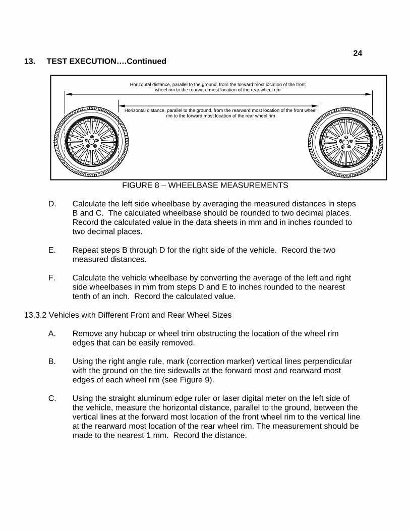
the vehicle, measure the horizontal distance, parallel to the ground, from the forward most edge of the front wheel rim to the rearward most edge of the rear wheel rim. The measurement should be made to the nearest 1 mm. Record the distance (see Figure 8).
C. Using the straight aluminum edge ruler or laser digital meter on the left side of
the vehicle, measure the horizontal distance, parallel to the ground, between the rearward most edge of the front wheel rim to the forward most edge of the rear wheel rim. The measurement should be made to the nearest 1 mm (see Figure 8). Record the distance.
For example for any given 4 measurements:
(1662 (mm) + 1661 (mm) + 1663 (mm) + 1661 (mm)) ÷ 4 = 1661.75 (mm) = 65.42 (in)
For example for any given front and rear track width measurements:
(1661.75 (mm) + 1663.5 (mm)) ÷ 2 = 1662.63 (mm) = 65.5 (in)
2413. TEST EXECUTION….Continued
FIGURE 8 – WHEELBASE MEASUREMENTS
D. Calculate the left side wheelbase by averaging the measured distances in steps
B and C. The calculated wheelbase should be rounded to two decimal places. Record the calculated value in the data sheets in mm and in inches rounded to two decimal places.
E. Repeat steps B through D for the right side of the vehicle. Record the two
measured distances. F. Calculate the vehicle wheelbase by converting the average of the left and right
side wheelbases in mm from steps D and E to inches rounded to the nearest tenth of an inch. Record the calculated value.
13.3.2 Vehicles with Different Front and Rear Wheel Sizes
A. Remove any hubcap or wheel trim obstructing the location of the wheel rim edges that can be easily removed.
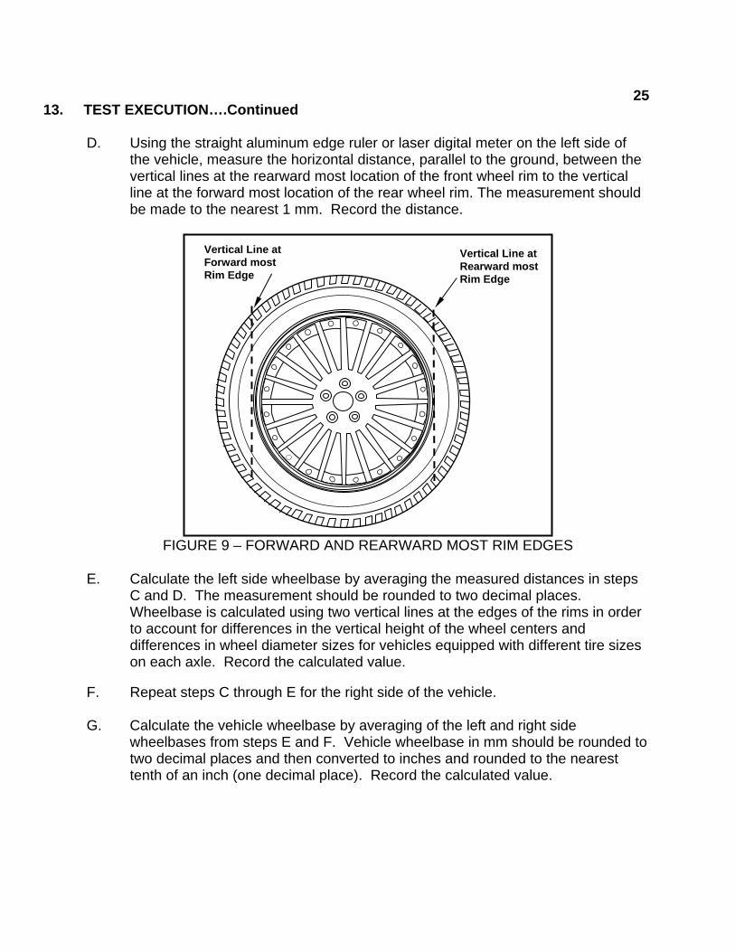
B. Using the right angle rule, mark (correction marker) vertical lines perpendicular
with the ground on the tire sidewalls at the forward most and rearward most edges of each wheel rim (see Figure 9).
C. Using the straight aluminum edge ruler or laser digital meter on the left side of
the vehicle, measure the horizontal distance, parallel to the ground, between the vertical lines at the forward most location of the front wheel rim to the vertical line at the rearward most location of the rear wheel rim. The measurement should be made to the nearest 1 mm. Record the distance.
Horizontal distance, parallel to the ground, from the forward most location of the front wheel rim to the rearward most location of the rear wheel rim
Horizontal distance, parallel to the ground, from the rearward most location of the front wheel rim to the forward most location of the rear wheel rim
2513. TEST EXECUTION….Continued
D. Using the straight aluminum edge ruler or laser digital meter on the left side of the vehicle, measure the horizontal distance, parallel to the ground, between the vertical lines at the rearward most location of the front wheel rim to the vertical line at the forward most location of the rear wheel rim. The measurement should be made to the nearest 1 mm. Record the distance.
FIGURE 9 – FORWARD AND REARWARD MOST RIM EDGES
E. Calculate the left side wheelbase by averaging the measured distances in steps
C and D. The measurement should be rounded to two decimal places. Wheelbase is calculated using two vertical lines at the edges of the rims in order to account for differences in the vertical height of the wheel centers and differences in wheel diameter sizes for vehicles equipped with different tire sizes on each axle. Record the calculated value.
F. Repeat steps C through E for the right side of the vehicle.
G. Calculate the vehicle wheelbase by averaging of the left and right side
wheelbases from steps E and F. Vehicle wheelbase in mm should be rounded to two decimal places and then converted to inches and rounded to the nearest tenth of an inch (one decimal place). Record the calculated value.
Vertical Line at Rearward most Rim Edge
Vertical Line at Forward most Rim Edge

2613. TEST EXECUTION….Continued 13.3.3 Vehicles with Wheelbases greater than 3,658 mm (144 inches).
NOTE: This procedure is not necessary if the laser digital meter was used in section 13.3.1 or 13.3.2.
A. Repeat the procedure in section 13.3.1 or section 13.3.2, as appropriate using a
7,620 mm (300 inches) metric steel tape measure instead of the aluminum ruler.
NOTE: Ensure that while measuring the tape measure is taught and parallel with the ground using the inclinometer.
13.4 Vehicle Footprint (Data Sheet 3)
A. Calculate vehicle “Foot Print” to the nearest tenth of a square foot. The footprint
is the product of track width (measured in inches and rounded to the nearest tenth) times wheelbase (measured in inches and rounded to the nearest tenth) divided by 144 and then rounded to the nearest tenth of a square foot.
B. Record the calculated value.
13.5 Compare Data (Data Sheet 4)
A. Compare the manufacturer’s reported track width, wheelbase and footprint values with those measured and calculated.
B. Record any discrepancies (differences between reported, measured and
calculated). The COTR shall determine whether an apparent non-conformance exists.
C. Any discrepancies could be a possible non-conformance with Part 537.
D. Determine whether the OVSC measurements of the vehicle and calculated
footprint from those measurements are within the range of the manufacturer’s reported values plus the tolerances, (i.e., the design and manufacturing tolerance values).
E. Contact the COTR if any of the OVSC measurements are outside the range of
the manufacturer’s values.
2714. POST TEST REQUIREMENTS
A. Verify all data sheets have been completed and all photographs taken. B. Complete the Vehicle Condition Report form including a word description of the
vehicle’s post test condition.
15. REPORTS 15.1. MONTHLY STATUS REPORTS
The contractor shall submit a monthly Test Status Report and a Vehicle Status Report to the COTR. The Vehicle Status report shall be submitted until all vehicles are disposed of. Samples of the required reports are found in the report forms section.
15.2. APPARENT NON-CONFORMANCE
Any indication of an apparent discrepancy or non-conformance shall be communicated by telephone to the COTR within 24 hours with written notification mailed within 48 hours (Saturdays and Sundays excluded). A Notice of Non-conformance (see report forms section) with a copy of the particular test data sheet(s) and the preliminary data shall be included.
15.3 FINAL TEST REPORTS 15.3.1 COPIES
In the case of an apparent discrepancy or non-conformance, two paper copies and electronic copies in both Word and pdf formats of the Final Test Report shall be submitted to the COTR for acceptance within three weeks of test completion. The Final Test Report format to be used by all contractors can be found in the "Report Section". Where there has been no indication of an apparent non-conformance, one paper copy and electronic copies in both Word and pdf formats of each Final Test Report shall be submitted to the COTR for acceptance within three weeks of test completion. No payment of contractor's invoices for conducting compliance tests will be made prior to the Final Test Report acceptance by the COTR. Contractors are requested to NOT submit invoices before the COTR is provided with copies of the Final Test Report.

2815. REPORTS….Continued
Contractors are required to submit the first Final Test Report in draft form within one week after the compliance test is conducted. The contractor and the COTR will then be able to discuss the details of both test conduct and report content early in the compliance test program.
Contractors are required to PROOF READ all Final Test Reports before submittal to the COTR. The OVSC will not act as a report quality control office for contractors. Reports containing a significant number of errors will be returned to the contractor for correction, and a "hold" will be placed on invoice payment for the particular test.
15.3.2 REQUIREMENTS
The Final Test Report and associated documentation (including photographs) are relied upon as the chronicle of the test verification. The Final Test Report will be released to the public domain after review and acceptance by the COTR. For these reasons, each final report must be a complete document capable of standing by itself. The contractor should use DETAILED descriptions of all test validation events. Any events that are not directly associated with the regulation but are of technical interest should also be included. The contractor should include as much DETAIL as possible in the report. Instructions for the preparation of the first three pages of the final test report are provided for standardization.

2915. REPORTS….Continued 15.3.3 FIRST THREE PAGES
A. FRONT COVER
A heavy paperback cover (or transparency) shall be provided for the protection of the final report. The information required on the cover is as follows: (1) Final Report Number such as 537-ABC-XX-001, where –
537 is the Regulation tested ABC are the initials for the laboratory XX is the Fiscal Year of the test program 001 is the Group Number (001 for the 1st test,
002 for the 2nd test, etc.)
(2) Final Report Title And Subtitle such as CONFORMANCE TESTING FOR 49 CFR 537 Automotive Fuel Economy Reports * * * * * * * * * * * * * * * * ABC Motor Company 20XX Saferider 4-door sedan NHTSA No. CX0401
(3) Contractor's Name and Address such as
TESTING LABORATORIES, INC. 4335 West Dearborn Street Detroit, Michigan 48090-1234
NOTE: DOT SYMBOL WILL BE PLACED BETWEEN ITEMS (3) AND (4)
(4) Date of Final Report completion (5) The words "FINAL REPORT"
(6) The sponsoring agency's name and address as follows
U. S. DEPARTMENT OF TRANSPORTATION National Highway Traffic Safety Administration
Enforcement Office of Vehicle Safety Compliance
Mail Code: NVS-220, Room W43-481 1200 New Jersey Ave., SE
Washington, DC 20590

3015. REPORTS….Continued
B. FIRST PAGE AFTER COVER PAGE
When a contract test laboratory is reporting, a disclaimer statement and an acceptance signature block for the COTR shall be provided as follows:
This publication is distributed by the National Highway Traffic Safety Administration in the interest of information exchange. Opinions, findings and conclusions expressed in this publication are those of the author(s) and not necessarily those of the Department of Transportation or the National Highway Traffic Safety Administration. The United States Government assumes no liability for its contents or use thereof. If trade or manufacturers' names or products are mentioned, it is only because they are considered essential to the object of the publication and should not be construed as an endorsement.
Prepared By: ______________________________ Approved By: ______________________________ * Approval Date: _____________________________ * FINAL REPORT ACCEPTANCE BY OVSC: * Accepted By: ________________________ Acceptance Date: __________________________ _
* These lines not required when OVSC staff writes the Test Report
3115. REPORTS....Continued
C. SECOND PAGE AFTER FRONT COVER
A completed Technical Report Documentation Page (Form DOT F1700.7) shall be completed for those items that are applicable with the other spaces left blank. Sample data for the applicable block numbers of the title page follows.
Block 1 — REPORT NUMBER
537-ABC-XX-001
Block 2 — GOVERNMENT ACCESSION NUMBER
Leave blank
Block 3 — RECIPIENT'S CATALOG NUMBER
Leave blank
Block 4 — TITLE AND SUBTITLE
Final Report of 49 CFR Part 537 Conformance Validation of 200X Saferider 4-door sedan, NHTSA No. CX0401
Block 5 — REPORT DATE
Month Day, 20XX
Block 6 — PERFORMING ORGANIZATION CODE
ABC
Block 7 — AUTHOR(S)
John Smith, Project Manager Bill Doe, Project Engineer
Block 8 — PERFORMING ORGANIZATION REPORT NUMBER
ABC-DOT-XXX-001
3215. REPORTS....Continued
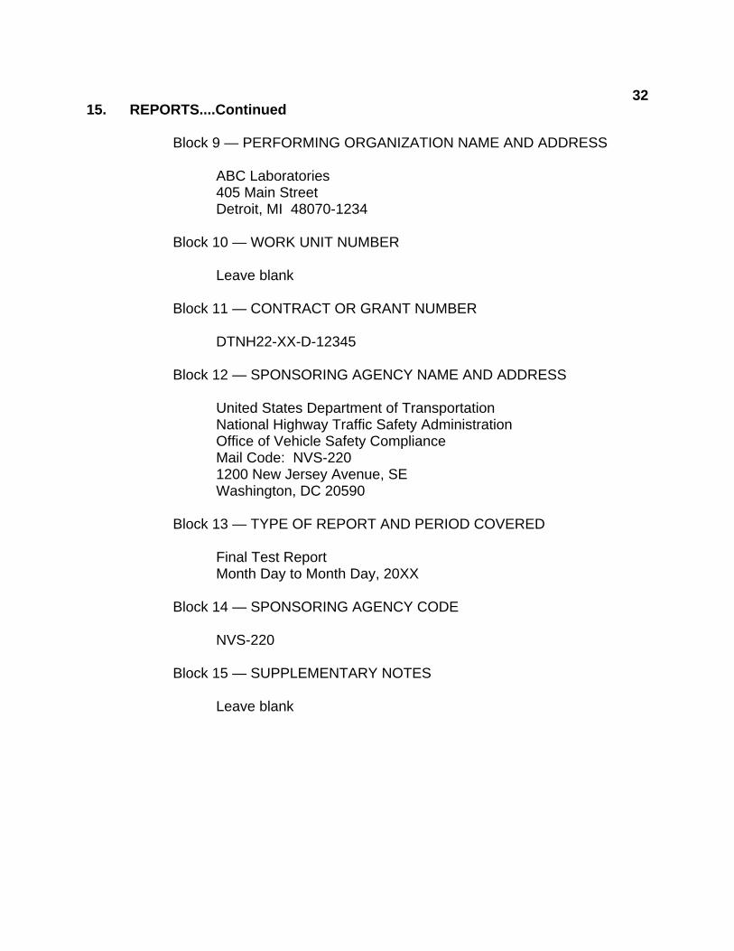
Block 9 — PERFORMING ORGANIZATION NAME AND ADDRESS
ABC Laboratories 405 Main Street Detroit, MI 48070-1234
Block 10 — WORK UNIT NUMBER
Leave blank
Block 11 — CONTRACT OR GRANT NUMBER
DTNH22-XX-D-12345
Block 12 — SPONSORING AGENCY NAME AND ADDRESS
United States Department of Transportation National Highway Traffic Safety Administration Office of Vehicle Safety Compliance Mail Code: NVS-220 1200 New Jersey Avenue, SE Washington, DC 20590
Block 13 — TYPE OF REPORT AND PERIOD COVERED
Final Test Report
Month Day to Month Day, 20XX
Block 14 — SPONSORING AGENCY CODE
NVS-220
Block 15 — SUPPLEMENTARY NOTES
Leave blank

3315. REPORTS....Continued
Block 16 — ABSTRACT
Conformance validations were conducted on the subject 200X Saferider 4-door sedan in accordance with the specifications of the Office of Vehicle Safety Compliance Test Procedure No. TP- 537 -0X for the determination of 49 CFR 537 Automotive Fuel Economy Reports. The test non-conformances identified were as follows:
None
NOTE: Above wording must be shown with appropriate changes made for a particular compliance test. Any questions should be resolved with the COTR.
Block 17 — KEY WORDS
Conformance Validation Safety Engineering 49 CFR Part 537
Block 18 — DISTRIBUTION STATEMENT
Copies of this report are available from —
National Highway Traffic Safety Administration Technical Information Services Division, NPO-411 1200 New Jersey Avenue, SE (ROOM E12-100) Washington, DC 20590
Block 19 — SECURITY CLASSIFICATION OF REPORT
Unclassified
Block 20 — SECURITY CLASSIFICATION OF PAGE
Unclassified
Block 21 — NUMBER OF PAGES
Add appropriate number
3415. REPORTS....Continued
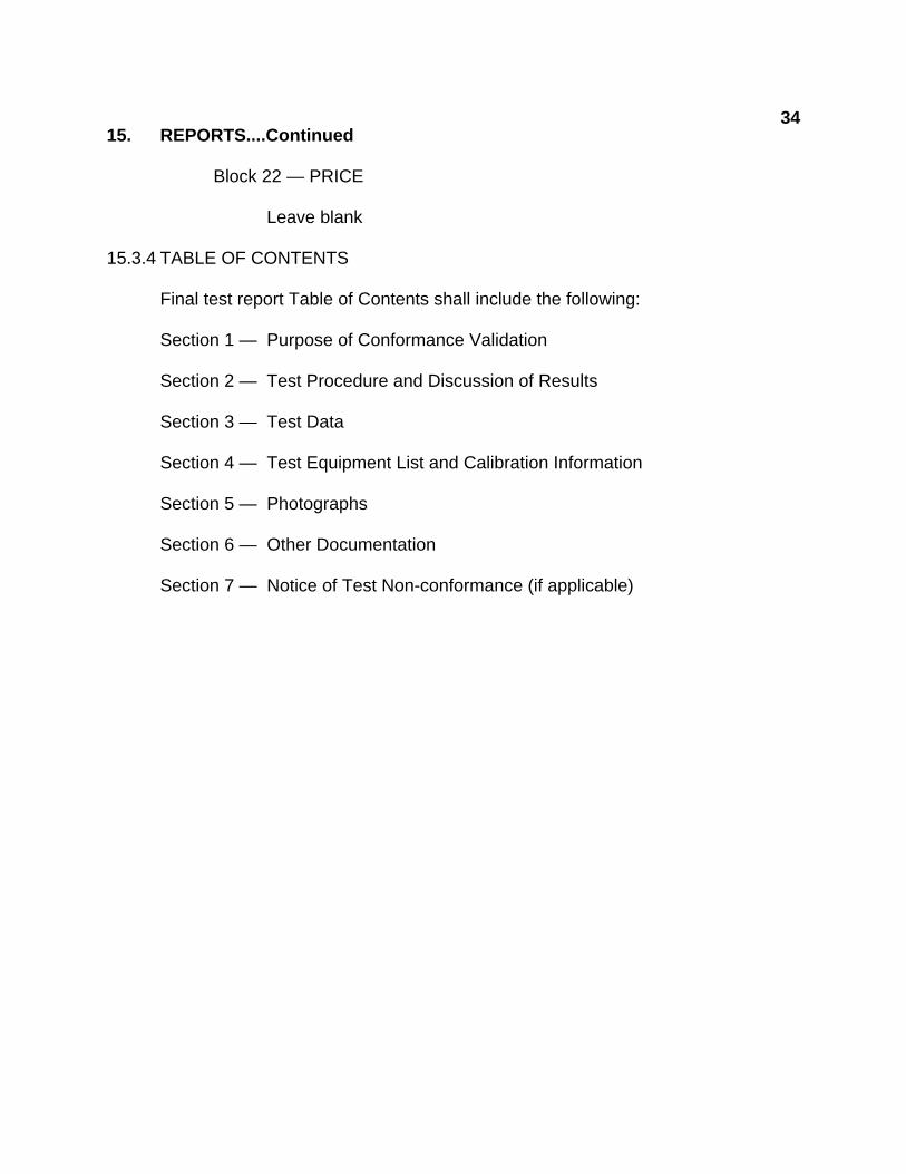
Block 22 — PRICE
Leave blank 15.3.4 TABLE OF CONTENTS
Final test report Table of Contents shall include the following:
Section 1 — Purpose of Conformance Validation
Section 2 — Test Procedure and Discussion of Results
Section 3 — Test Data
Section 4 — Test Equipment List and Calibration Information
Section 5 — Photographs Section 6 — Other Documentation
Section 7 — Notice of Test Non-conformance (if applicable)
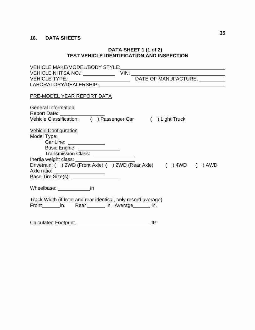
3516. DATA SHEETS DATA SHEET 1 (1 of 2)
TEST VEHICLE IDENTIFICATION AND INSPECTION VEHICLE MAKE/MODEL/BODY STYLE: VEHICLE NHTSA NO.: VIN: VEHICLE TYPE: DATE OF MANUFACTURE: LABORATORY/DEALERSHIP: PRE-MODEL YEAR REPORT DATA General Information Report Date: Vehicle Classification: ( ) Passenger Car ( ) Light Truck
Vehicle Configuration Model Type: Car Line: Basic Engine: Transmission Class: Inertia weight class: Drivetrain: ( ) 2WD (Front Axle) ( ) 2WD (Rear Axle) ( ) 4WD ( ) AWD Axle ratio: Base Tire Size(s): Wheelbase: in
Track Width (if front and rear identical, only record average) Front in. Rear in. Average in. Calculated Footprint ft²
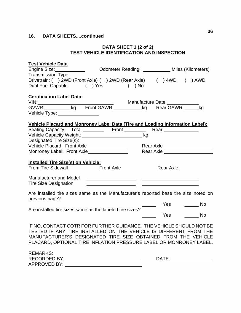
3616. DATA SHEETS....continued DATA SHEET 1 (2 of 2) TEST VEHICLE IDENTIFICATION AND INSPECTION Test Vehicle Data Engine Size: Odometer Reading: Miles (Kilometers) Transmission Type: Drivetrain: ( ) 2WD (Front Axle) ( ) 2WD (Rear Axle) ( ) 4WD ( ) AWD Dual Fuel Capable: ( ) Yes ( ) No Certification Label Data: VIN: Manufacture Date: GVWR: kg Front GAWR: kg Rear GAWR kg Vehicle Type: Vehicle Placard and Monroney Label Data (Tire and Loading Information Label): Seating Capacity: Total Front Rear Vehicle Capacity Weight: kg Designated Tire Size(s): Vehicle Placard: Front Axle Rear Axle Monroney Label: Front Axle Rear Axle Installed Tire Size(s) on Vehicle: From Tire Sidewall Front Axle Rear Axle
Manufacturer and Model Tire Size Designation Are installed tire sizes same as the Manufacturer’s reported base tire size noted on previous page? Yes No Are installed tire sizes same as the labeled tire sizes? Yes No IF NO, CONTACT COTR FOR FURTHER GUIDANCE. THE VEHICLE SHOULD NOT BE TESTED IF ANY TIRE INSTALLED ON THE VEHICLE IS DIFFERENT FROM THE MANUFACTURER’S DESIGNATED TIRE SIZE OBTAINED FROM THE VEHICLE PLACARD, OPTIONAL TIRE INFLATION PRESSURE LABEL OR MONRONEY LABEL. REMARKS: RECORDED BY: DATE: APPROVED BY:

3716. DATA SHEETS....continued
DATA SHEET 2
TEST VEHICLE PREPARATION VEHICLE MAKE/MODEL/BODY STYLE: VEHICLE NHTSA NO.: VIN: VEHICLE TYPE: DATE OF MANUFACTURE: LABORATORY/DEALERSHIP: Is vehicle at unloaded vehicle weight condition? ( ) Yes ( ) No If not, fill the vehicle to the appropriate fluid capacities and check when completed:
Fuel ( ) Completed Engine Oil ( ) Completed Coolant ( ) Completed Transmission fluid ( ) Completed Brake fluid ( ) Completed Windshield washer fluid ( ) Completed
Verify the Tire Pressures and if necessary inflate the vehicle tires to the cold tire pressure indicated on the tire placard:
Required: Front Axle kPa Rear Axle kPa Actual: LF kPa LR kPa
RF kPa RR kPa Verify that the test surface is level on each side of the vehicle using the straight aluminum edge ruler and the digital inclinometer. Inclinometer reading on:
Front of vehicle: Left side of vehicle: Right side of vehicle: Rear of vehicle:
REMARKS: RECORDED BY: DATE: APPROVED BY:

3816. DATA SHEETS....continued
DATA SHEET 3 (sheet 1 of 2) VEHICLE MEASUREMENTS
VEHICLE MAKE/MODEL/BODY STYLE: VEHICLE NHTSA NO.: VIN: VEHICLE TYPE: DATE OF MANUFACTURE: LABORATORY/DEALERSHIP: Track Width
Front Axle Measured Distances Value
(mm) Value (in)
1. With TEDTs on left sides of tires: Horizontal distance between the edges of each TEDT from front of tires to the nearest mm
2. With TEDTs on left sides of tires: Horizontal distance between the edges of each TEDT from rear of tires to the nearest mm
3. With TEDTs on right sides of tires: Horizontal distance between the edges of each TEDT from front of tires to the nearest mm
4. With TEDTs on right sides of tires: Horizontal distance between the edges of each TEDT from rear of tires to the nearest mm
5. Front Axle Track Width (average of items 1 through 4 and rounded to two decimal places)
Rear Axle Measured Distances Value (mm)
Value (in)
1. With TEDTs on left sides of tires: Horizontal distance between the edges of each TEDT from front of tires to the nearest mm
2. With TEDTs on left sides of tires: Horizontal distance between the edges of each TEDT from rear of tires to the nearest mm
3. With TEDTs on right sides of tires: Horizontal distance between the edges of each TEDT from front of tires to the nearest mm
4. With TEDTs on right sides of tires: Horizontal distance between the edges of each TEDT from rear of tires to the nearest mm
5. Rear Axle Track Width (average of items 1 through 4 and rounded to two decimal places)
The vehicle track width is the calculated average of the front and rear track widths in mm (step 5 in each table) rounded to two decimal places and then converted to inches by dividing by 25.4 mm/in and rounding to the nearest tenth of an inch or one decimal place.) Vehicle Track Width = (in.)
16. DATA SHEETS....continued
39
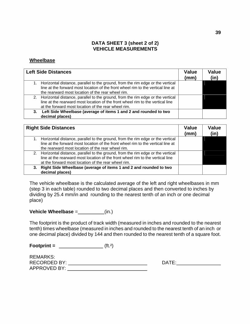
DATA SHEET 3 (sheet 2 of 2) VEHICLE MEASUREMENTS
Wheelbase
Left Side Distances Value
(mm) Value (in)
1. Horizontal distance, parallel to the ground, from the rim edge or the vertical line at the forward most location of the front wheel rim to the vertical line at the rearward most location of the rear wheel rim.
2. Horizontal distance, parallel to the ground, from the rim edge or the vertical line at the rearward most location of the front wheel rim to the vertical line at the forward most location of the rear wheel rim.
3. Left Side Wheelbase (average of items 1 and 2 and rounded to two decimal places)
Right Side Distances Value
(mm) Value (in)
1. Horizontal distance, parallel to the ground, from the rim edge or the vertical line at the forward most location of the front wheel rim to the vertical line at the rearward most location of the rear wheel rim.
2. Horizontal distance, parallel to the ground, from the rim edge or the vertical line at the rearward most location of the front wheel rim to the vertical line at the forward most location of the rear wheel rim.
3. Right Side Wheelbase (average of items 1 and 2 and rounded to two decimal places)
The vehicle wheelbase is the calculated average of the left and right wheelbases in mm (step 3 in each table) rounded to two decimal places and then converted to inches by dividing by 25.4 mm/in and rounding to the nearest tenth of an inch or one decimal place) Vehicle Wheelbase = (in.) The footprint is the product of track width (measured in inches and rounded to the nearest tenth) times wheelbase (measured in inches and rounded to the nearest tenth of an inch or one decimal place) divided by 144 and then rounded to the nearest tenth of a square foot. Footprint = (ft.²) REMARKS: RECORDED BY: DATE: APPROVED BY:

4016. DATA SHEETS….Continued
DATA SHEET 4 (1 of 2) COMPARE DATA
VEHICLE MAKE/MODEL/BODY STYLE: VEHICLE NHTSA NO.: VIN: VEHICLE TYPE: DATE OF MANUFACTURE: LABORATORY/DEALERSHIP: REQUIREMENTS
Item
OVSC
Measured Value
(A)
Manufacturer’s Reported Value
(B)
Tolerances4
(+/-)
(C)
Range (Manufacturer’s reported value +/- tolerances)
(B-C to B+C) Front Track Width Rear Track Width Vehicle Track Width Left (Driver Side) Wheelbase Right (Passenger Side) Wheelbase
Vehicle Wheelbase Footprint
Are the OVSC vehicle track width, wheelbase and footprint values within the range of the manufacturer’s reported values plus the tolerances? Vehicle Measurement or Calculated Value
Yes (B-C < A < B+C)
No (B-C > A > B+C)
Track Width
Wheelbase
Footprint
REMARKS: RECORDED BY: DATE: APPROVED BY:
4 The tolerances include the manufacturer’s design and manufacturing tolerances. If the manufacturer has not provided tolerances, OVSC may assign default values based upon the results of measured vehicles.
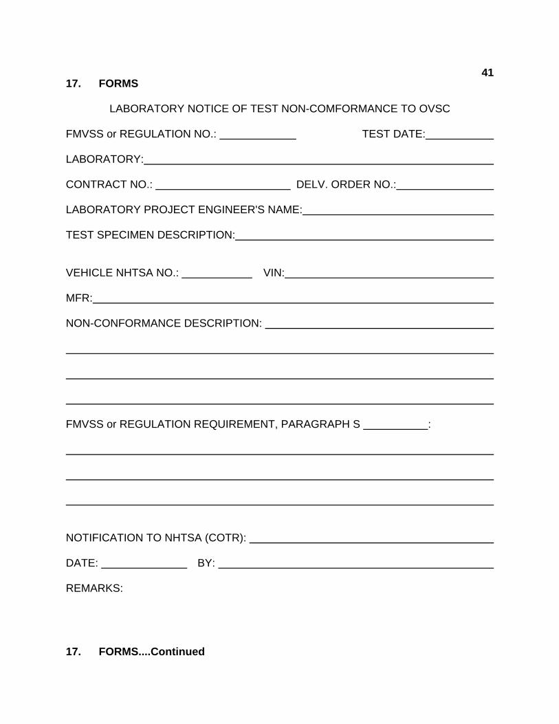
4117. FORMS LABORATORY NOTICE OF TEST NON-COMFORMANCE TO OVSC FMVSS or REGULATION NO.: TEST DATE: LABORATORY: CONTRACT NO.: DELV. ORDER NO.: LABORATORY PROJECT ENGINEER'S NAME: TEST SPECIMEN DESCRIPTION:
VEHICLE NHTSA NO.: VIN: MFR: NON-CONFORMANCE DESCRIPTION: FMVSS or REGULATION REQUIREMENT, PARAGRAPH S : NOTIFICATION TO NHTSA (COTR): DATE: BY: REMARKS: 17. FORMS....Continued
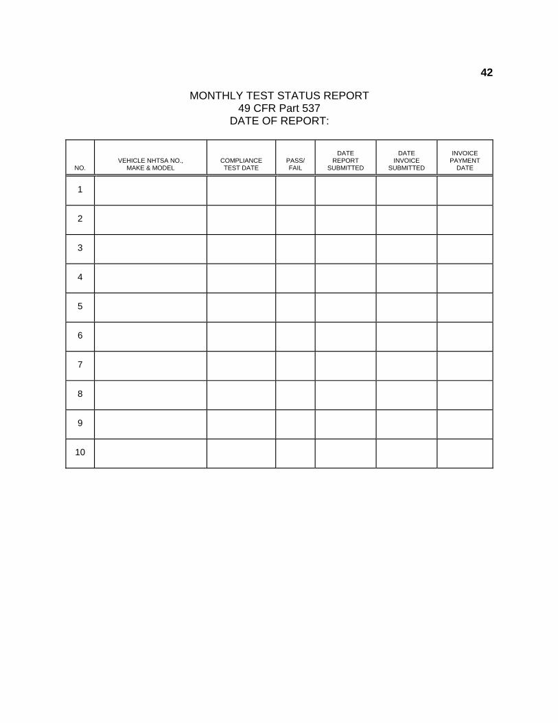
42 MONTHLY TEST STATUS REPORT 49 CFR Part 537 DATE OF REPORT:
NO.
VEHICLE NHTSA NO., MAKE & MODEL
COMPLIANCE TEST DATE
PASS/ FAIL
DATE
REPORT SUBMITTED
DATE
INVOICE SUBMITTED
INVOICE
PAYMENT DATE
1
2
3
4
5
6
7
8
9
10
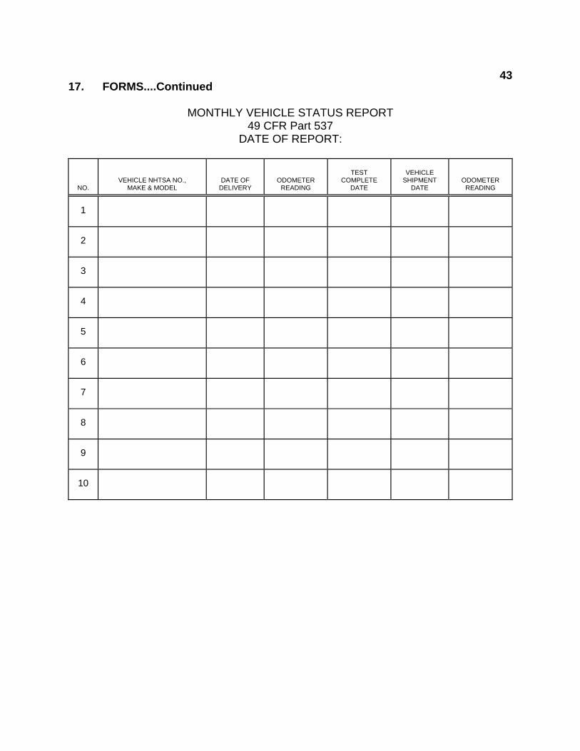
4317. FORMS....Continued MONTHLY VEHICLE STATUS REPORT 49 CFR Part 537 DATE OF REPORT:
NO.
VEHICLE NHTSA NO., MAKE & MODEL
DATE OF DELIVERY
ODOMETER READING
TEST
COMPLETE DATE
VEHICLE
SHIPMENT DATE
ODOMETER READING
1
2
3
4
5
6
7
8
9
10