krautkramer dm4 seriesintechnd.nextmp.net/downloads/manuals/dms 4 series manual... ·...
TRANSCRIPT
Krautkramer DM4 SeriesOperating Manual
GEInspection Technologies Ultrasonics
www.ge.com/inspectiontechnologies
DM4E, DM4, DM4 DLTechnical Reference and Operating Manual
Ident-Nr. 28 593084-028-593
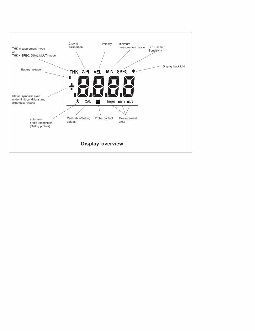
You will find a function overview of the DM4E, DM4 and DM4 DL as well as an illustration of the instrument displayincluding all display symbols and their meaning.
This will help you to find information a great deal faster when reading the operating manual.
This issue 05, 01/01 applies to the following software version:
V 4.16
All rights reserved for technical changes.
0-2 Ausgabe 01, 01/99 Krautkrämer USM 25
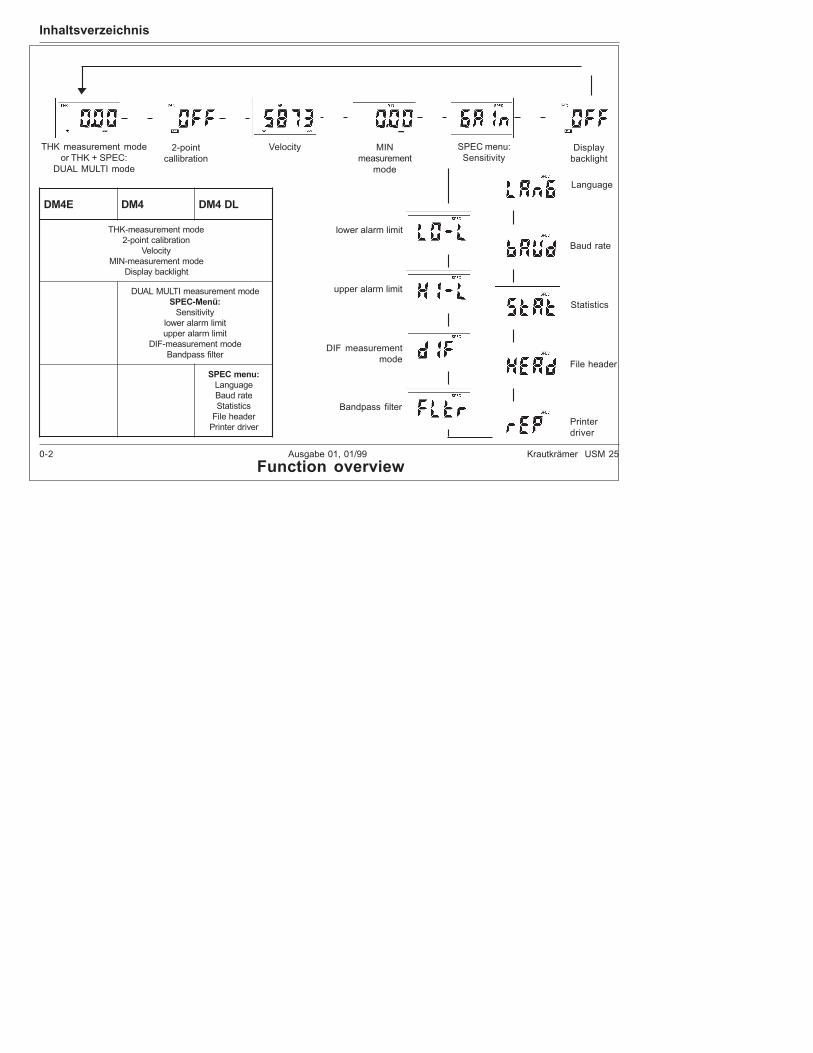
Inhaltsverzeichnis
SPEC menu:Sensitivity
THK measurement modeor THK + SPEC:
DUAL MULTI mode
2-pointcallibration
Velocity MINmeasurement
mode
Displaybacklight
E4MD 4MD LD4MD
edomtnemerusaem-KHTnoitarbilactniop-2
yticoleVedomtnemerusaem-NIM
thgilkcabyalpsiD
edomtnemerusaemITLUMLAUD:üneM-CEPS
ytivitisneStimilmralarewoltimilmralareppu
edomtnemerusaem-FIDretlifssapdnaB
:unemCEPSegaugnaLetarduaBscitsitatS
redaeheliFrevirdretnirP
Function overview
Printerdriver
File header
Statistics
Baud rate
Language
Bandpass filter
DIF measurementmode
upper alarm limit
lower alarm limit
0-2 Ausgabe 01, 01/99 Krautkrämer USM 25
Function overview
THK measurement modeorTHK + SPEC: DUAL MULTI mode
2-pointcallibration
Velocity Minimummeasurement mode SPEC menu:
Sensitivity
Display backlight
Measurementunits
Probe contactCalibration/Settingvalues
automaticprobe recognition(Dialog probes)
Status symbols: over/under-limit conditions anddifferential values
Battery voltage
Display overview
Krautkramer DM4E / DM4 / DM4 DL Issue 05, 01/01 0-3
Content
1 Introduction ...................................... 1 -1
1.1 DM4E, DM4 and DM4 DL ........................ 1 -2
1.2 Information about this manual .............. 1 -5
1.3 Layout and presentationof this manual ......................................... 1 -6
1.4 Important remarksabout thickness testing ......................... 1 -7
Conditions for application ofultrasonic thickness gauges ..................... 1 -7
Operator training ...................................... 1 -8
Limits of ultrasonic testing ........................ 1 -8Ultrasonic thickness measurement ........... 1 -9
Influence of the test material .................... 1 -9
1.5 Important notes onthickness testing with the DM4 ........... 1 -11
Probe Zero Adjustment........................... 1 -11Couplant rests ........................................ 1 -12
Measurement precision .......................... 1 -12
Probes .................................................... 1 -12
DM4 DL Data Logger ............................. 1 -13
2 Scope of supply and accessories... 2 -1
2.1 Scope of delivery .................................... 2 -3
2.2 Required accessories ............................. 2 -4
2.3 Recommended accessories ................... 2 -4
2.4 Recommended outside products ........... 2 -6
3 Preparation for operation ................ 3 -1
3.1 Battery supply ......................................... 3 -2
Inserting batteries ..................................... 3 -2
3.2 Connecting the probe ............................. 3 -4
4 Basics of operation .......................... 4 -1
4.1 Display ..................................................... 4 -2
Display indications .................................... 4 -2
4.2 Keys ......................................................... 4 -4
4.3 Switching the instrument on and off ..... 4 -5
Indications after switching on .................... 4 -5
Dialog probes ............................................ 4 -5
0-4 Issue 05, 01/01 Krautkramer DM4E / DM4 / DM4 DL
Content
Non-dialog probes: DA3 modeor AUTO mode ......................................... 4 -6
Switching the instrument off ..................... 4 -7
4.4 Automatic instrument switch-off ........... 4 -7
4.5 Operation concept .................................. 4 -8
Selecting operation modes/functions ........ 4 -8
Changing settings/values ......................... 4 -8
4.6 Automatic probe zero adjustment ......... 4 -9
4.7 Automatic probe recognition............... 4 -10
4.8 Handling the probe ............................... 4 -10
5 Operation .......................................... 5 -1
5.1 Basic settings ......................................... 5 -2
Setting the display backlight ..................... 5 -2
Setting the units of measureand resolution ........................................... 5 -2
Setting the unit for sound velocity ............. 5 -3
5.2 Calibrating the instrument ...................... 5 -4
Calibration with a known sound velocity .... 5 -5
1-point calibration ...................................... 5 -6
2-point calibration ...................................... 5 -7
5.3 Thickness measurement....................... 5 -10
Standard measurement: THK mode......... 5 -10
Minimum capture measurement:MIN mode............................................... 5 -11
5.4 Additional functionsin the DM4 and DM4 DL ....................... 5 -13
Setting the sensitivity GAIN .................... 5 -13
Setting the alarm limits ........................... 5 -14
Switching the alarm off again ................. 5 -15
Difference mode: DIF .............................. 5 -15
Setting the bandpass filter:FLTR ............ 5 -16
Measuring through coatings:operating mode DUAL MULTI ................. 5 -17
5.5 Activating and deactivating functions 5 -19
Krautkramer DM4E / DM4 / DM4 DL Issue 05, 01/01 0-5
Content
6 Operation of the Data Logger(DM4 DL only) ................................... 6 -1
6.1 Data Logger ............................................. 6 -2
6.2 Setting the number of files ..................... 6 -3
6.3 Storing the measurement values ........... 6 -5
File selection ............................................ 6 -5
Storing measurement valuesin the selected file ..................................... 6 -6
Inhibiting a memory location ..................... 6 -8
Selecting a memory location .................... 6 -8
6.4 Viewing stored measurement values .... 6 -9
6.5 Deleting stored measurement values . 6 -11
Deleting and replacingindividual measurement values .............. 6 -11
Deleting a file .......................................... 6 -11Clearing the complete memory............... 6 -12
7 Documenting measurement values(DM4 DL only) ................................... 7 -1
7.1 Printing data ............................................ 7 -2
Preparing the printer .................................. 7 -2Selecting the baud rate ............................. 7 -3
Selecting the report language ................... 7 -3
Selecting the printer driver ........................ 7 -4
Selection of file header printout ................. 7 -5
Selection of statistics printout ................... 7 -5
Printing the measurement report ............... 7 -6
7.2 Transferring data to a PC ........................ 7 -8
Connnecting a PC ..................................... 7 -8
Transferring data ....................................... 7 -8
8 Care and maintenance ..................... 8 -1
8.1 Care ......................................................... 8 -2
Care of the instrument .............................. 8 -2
Handling AlMn batteries ............................ 8 -2
8.2 Maintenance ............................................ 8 -3
0-6 Issue 05, 01/01 Krautkramer DM4E / DM4 / DM4 DL
Content
9 Specifications ................................... 9 -1
10 Interfaces and peripherals ............. 10 -1
10.1 Interface RS 232 ................................... 10 -2
Data format ............................................ 10 -2
10.2 Pin layout of the 7 pinLemo socket (RS 232) ......................... 10 -3
11 Appendix ......................................... 11 -1
11.1 Application information ...................... 11 -2
General information ............................... 11 -2
Foreign inclusions inside the material .... 11 -2
Surface quality ....................................... 11 -2
Curved surfaces .................................... 11 -3Thickness measurementon hot test objects ................................. 11 -3
11.2 Sound velocity table ........................... 11 -5
11.3 Configuration of the Data Logger ...... 11 -7
11.4 EU declaration of conformity .............. 11 -9
11.5 Service addresses ...............................11 -10
12 Changes.......................................... 12 -1
13 Index ................................................ 13 -1

Krautkramer DM4E / DM4 / DM4 DL Issue 05, 01/01 1-1
Introduction 1
1-2 Issue 05, 01/01 Krautkramer DM4E / DM4 / DM4 DL
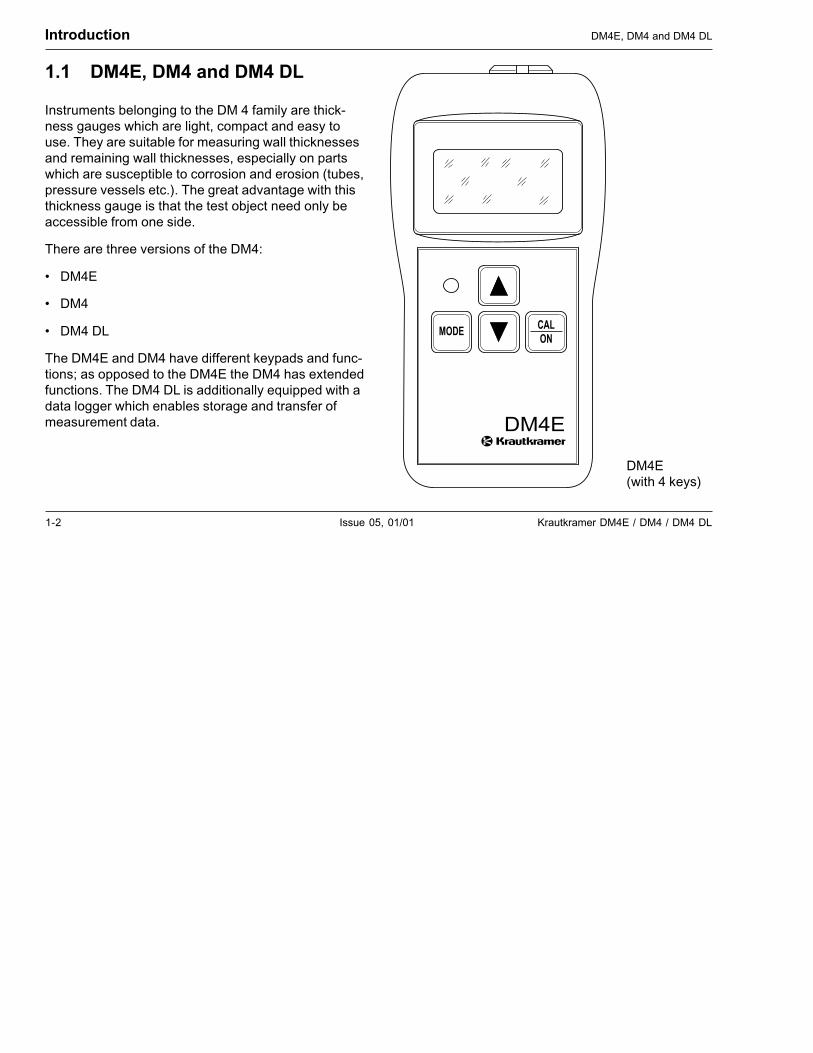
1.1 DM4E, DM4 and DM4 DL
Instruments belonging to the DM 4 family are thick-ness gauges which are light, compact and easy touse. They are suitable for measuring wall thicknessesand remaining wall thicknesses, especially on partswhich are susceptible to corrosion and erosion (tubes,pressure vessels etc.). The great advantage with thisthickness gauge is that the test object need only beaccessible from one side.
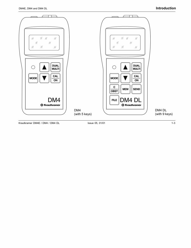
There are three versions of the DM4:
• DM4E
• DM4
• DM4 DL
The DM4E and DM4 have different keypads and func-tions; as opposed to the DM4E the DM4 has extendedfunctions. The DM4 DL is additionally equipped with adata logger which enables storage and transfer ofmeasurement data.
Introduction DM4E, DM4 and DM4 DL
CALON
MODE
DM4E
DM4E(with 4 keys)
Krautkramer DM4E / DM4 / DM4 DL Issue 05, 01/01 1-3
DM4E, DM4 and DM4 DL Introduction
DM4(with 5 keys)
DM4 DL(with 9 keys)
1-4 Issue 05, 01/01 Krautkramer DM4E / DM4 / DM4 DL
Introduction DM4E, DM4 and DM4 DL
Special features of all three versions(DM4E, DM4, DM4 DL):
• Automatic probe recognition; with DIALOG probesoptimum setting and performance of the instrument;especially for a higher measurement accuracy byindividually stored correction data in the probe
• Automatic probe zero for quick calibration
• Automatic V-path correction for measurementlinearity over the complete measurement range
• Digital resolution of 0.01 mm (for thicknesses up to99.99 mm) and 0.1 mm (for thicknesses > 99.99 mm)
• MIN mode with increased pulse repetition frequencyfor detection of the smallest measurement value
• Up to 200 hours operation with AlMn batteries
• Automatic gain adjustment
• Large, easy to read digital display with switchablebacklight
• Lightweight, ergonomic and rugged housing
Extended functions for DM4 and DM4 DL:
• Operating mode DUAL MULTI - measurementthrough coatings
• Manual gain adjustment
• Programmable minimum and maximum limits withLED alarm
• Difference mode for comparing the measuredthickness with a variable nominal value
Special features of the DM4 DL (Data Logger):
• Integrated Data Logger with a capacity for 5390values which can be divided into 999 files
• Access to the individual measurement values andfiles (viewing, editing and deleting),
• RS 232 interface for data transfer to a printer or PC(with special software)
Krautkramer DM4E / DM4 / DM4 DL Issue 05, 01/01 1-5
IntroductionInformation about this manual
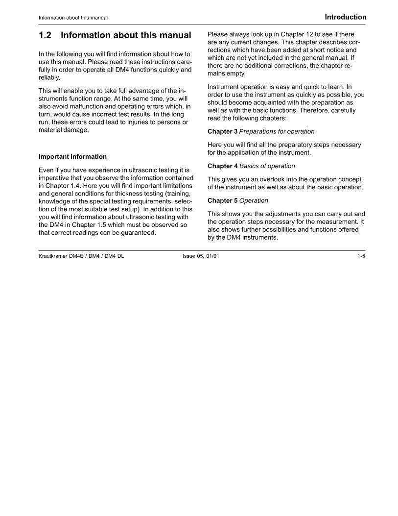
1.2 Information about this manual
In the following you will find information about how touse this manual. Please read these instructions care-fully in order to operate all DM4 functions quickly andreliably.
This will enable you to take full advantage of the in-struments function range. At the same time, you willalso avoid malfunction and operating errors which, inturn, would cause incorrect test results. In the longrun, these errors could lead to injuries to persons ormaterial damage.
Important information
Even if you have experience in ultrasonic testing it isimperative that you observe the information containedin Chapter 1.4. Here you will find important limitationsand general conditions for thickness testing (training,knowledge of the special testing requirements, selec-tion of the most suitable test setup). In addition to thisyou will find information about ultrasonic testing withthe DM4 in Chapter 1.5 which must be observed sothat correct readings can be guaranteed.
Please always look up in Chapter 12 to see if thereare any current changes. This chapter describes cor-rections which have been added at short notice andwhich are not yet included in the general manual. Ifthere are no additional corrections, the chapter re-mains empty.
Instrument operation is easy and quick to learn. Inorder to use the instrument as quickly as possible, youshould become acquainted with the preparation aswell as with the basic functions. Therefore, carefullyread the following chapters:
Chapter 3 Preparations for operation
Here you will find all the preparatory steps necessaryfor the application of the instrument.
Chapter 4 Basics of operation
This gives you an overlook into the operation conceptof the instrument as well as about the basic operation.
Chapter 5 Operation
This shows you the adjustments you can carry out andthe operation steps necessary for the measurement. Italso shows further possibilities and functions offeredby the DM4 instruments.
1-6 Issue 05, 01/01 Krautkramer DM4E / DM4 / DM4 DL
Introduction Layout and presentation of this manual
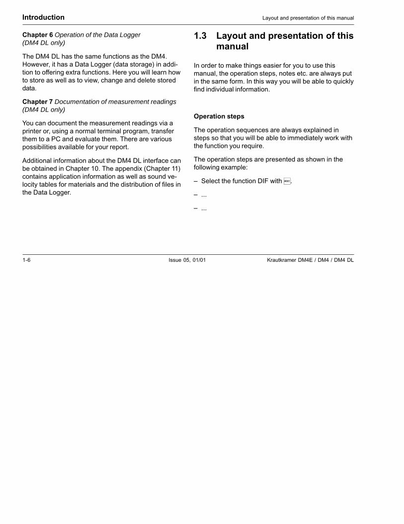
Chapter 6 Operation of the Data Logger(DM4 DL only)
The DM4 DL has the same functions as the DM4.However, it has a Data Logger (data storage) in addi-tion to offering extra functions. Here you will learn howto store as well as to view, change and delete storeddata.
Chapter 7 Documentation of measurement readings(DM4 DL only)
You can document the measurement readings via aprinter or, using a normal terminal program, transferthem to a PC and evaluate them. There are variouspossibilities available for your report.
Additional information about the DM4 DL interface canbe obtained in Chapter 10. The appendix (Chapter 11)contains application information as well as sound ve-locity tables for materials and the distribution of files inthe Data Logger.
1.3 Layout and presentation of thismanual
In order to make things easier for you to use thismanual, the operation steps, notes etc. are always putin the same form. In this way you will be able to quicklyfind individual information.
Operation steps
The operation sequences are always explained insteps so that you will be able to immediately work withthe function you require.
The operation steps are presented as shown in thefollowing example:
– Select the function DIF with �.
– ...
– ...
Krautkramer DM4E / DM4 / DM4 DL Issue 05, 01/01 1-7
IntroductionImportant remarks about thickness testing
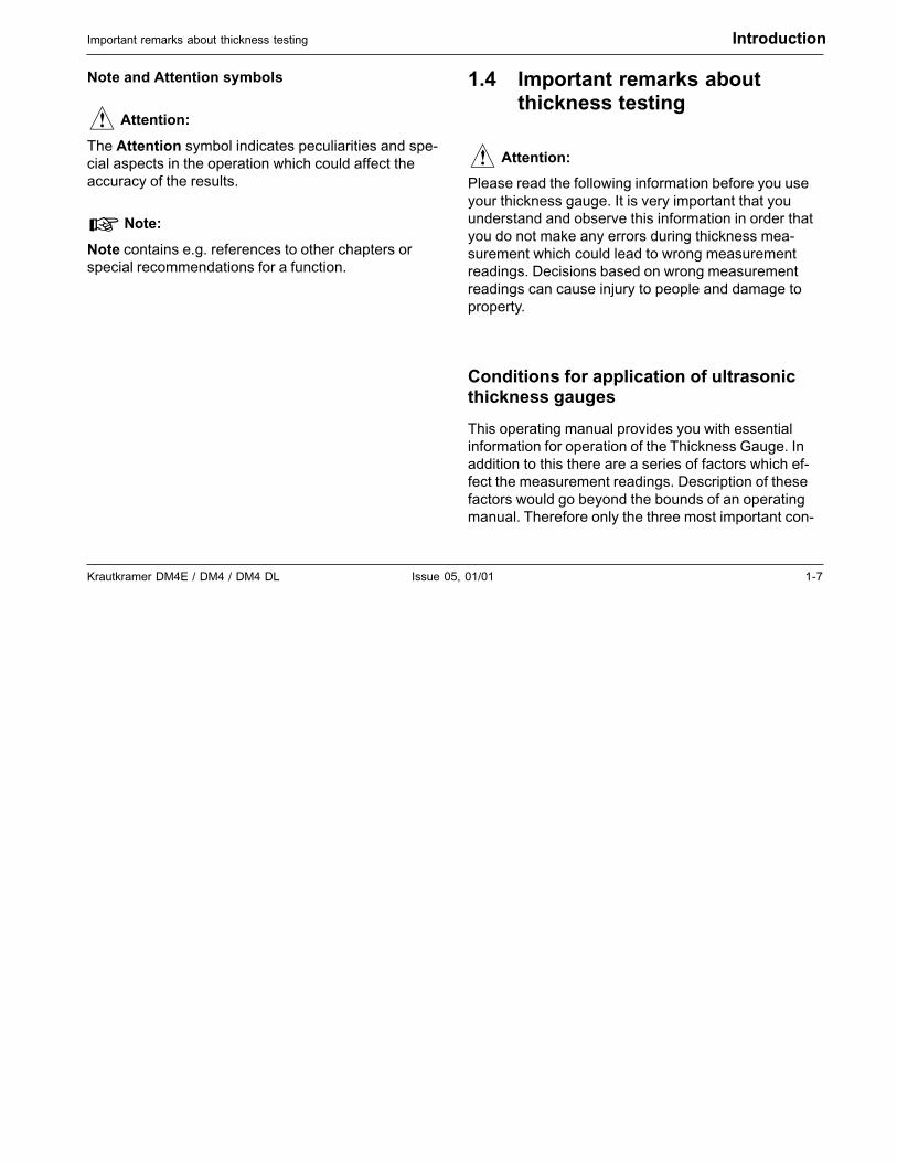
Note and Attention symbols
� Attention:
The Attention symbol indicates peculiarities and spe-cial aspects in the operation which could affect theaccuracy of the results.
� Note:
Note contains e.g. references to other chapters orspecial recommendations for a function.
1.4 Important remarks aboutthickness testing
� Attention:
Please read the following information before you useyour thickness gauge. It is very important that youunderstand and observe this information in order thatyou do not make any errors during thickness mea-surement which could lead to wrong measurementreadings. Decisions based on wrong measurementreadings can cause injury to people and damage toproperty.
Conditions for application of ultrasonicthickness gauges
This operating manual provides you with essentialinformation for operation of the Thickness Gauge. Inaddition to this there are a series of factors which ef-fect the measurement readings. Description of thesefactors would go beyond the bounds of an operatingmanual. Therefore only the three most important con-
1-8 Issue 05, 01/01 Krautkramer DM4E / DM4 / DM4 DL
Introduction Important remarks about thickness testing
ditions are listed for a reliable thickness measurement:
• Operator training
• Knowledge of the special technical requirementsand limits of testing
• Selection of the most suitable test setup
Operator training
For operation of an ultrasonic measurement instru-ment adequate training is required in the field of ultra-sonic thickness measurement. Appropriate trainingincludes, for example, knowledge of the following:
• Theory of sound propagation in materials
• The effects of material sound velocity
• Behavior of sound waves at interfaces betweendifferent materials
• Propagation of the sound beam in the material
• Effect of the materials surface quality.
Insufficient knowledge of the above mentioned fieldscan cause incorrect test results and could thus haveunforseeable consequences. Information about exist-ing possibilities with regard to ultrasonic operator train-ing as well as qualifications and certificates can beobtained from the national NDT organizations, e.g. inGermany: the Deutschen Gesellschaft für Zerstö-rungsfreie Prüfung e.V., Motardstrasse 54, D-13629Berlin; or from Krautkrämer GmbH & Co., TrainingDepartment.
Krautkrämer holds courses at regular intervals fortraining specialists in the field of ultrasonic testing.Dates will be given on request.
Limits of ultrasonic testing
The ultrasonic test information only concerns the areaof the test object which is covered by the sound beamof the probe being used. Therefore care should be takenin case conclusions from the results of the tested areaare drawn from the untested areas of the test object.Such conclusions are normally only allowed whenextensive experience exists with regard to the testobject and proven methods of statistical data acquisi-tion are available.
Krautkramer DM4E / DM4 / DM4 DL Issue 05, 01/01 1-9
Important remarks about thickness testing Introduction
Interfaces within the test object can completely reflectthe sound beam so that deeper reflection positions,e.g. backwall of the test object, can no longer bereached by the sound beam. Therefore it must be en-sured that the area to be tested is able to be coveredby the sound beam.
Ultrasonic thickness measurement
Each thickness measurement with ultrasonics isbased on a time of flight measurement of the soundpulse in the test object. The condition for exact mea-surement results is therefore a constant sound veloc-ity in the test object. Normally this condition is fulfilledwith steel objects, even with different alloy contents.The sound velocity changes so little that it is only no-ticeable with precision measurements. In other materi-als, e.g. nonferrous heavy metal or plastics, the soundvelocity is subject to greater changes. Due to this, themeasurement accuracy can be effected.
Influence of the test material
If the material is not homogeneous different soundvelocities can exist in various areas of the test object.Therefore an average sound velocity is to be takeninto account when calibrating the instrument.
The best results are however achieved when the in-strument is calibrated on a reference block made ofthe same material as the test object. This calibrationblock should have plane-parallel surfaces and have athickness which corresponds to the thickness of thetest object. In addition to this, the operator should un-derstand that changes to the sound velocity occurwhen material is heat treated. This must be taken intoaccount with the evaluation of the thickness accuracymeasured by the instrument.
If substantial sound velocity changes are to be reck-oned with then the instrument calibration should bemade at shorter intervals to the existing sound veloc-ity. If this is not made, wrong thickness readings willoccur.
1-10 Issue 05, 01/01 Krautkramer DM4E / DM4 / DM4 DL
Introduction Important remarks about thickness testing
Effects of temperature changes
The sound velocity in the test object changes with thetemperature of the material. Therefore, under certainconditions, larger measurement errors will be pro-duced if instrument calibration is made on a cold refer-ence block and then the thickness measurement car-ried out on a warm test object. Such measurementerrors can be avoided when calibration is made with atempered reference block or when the temperatureeffect on the sound velocity is taken into account usinga correction table.
Remaining thickness measurement
Measurement of the remaining thickness on the insideof eroded or corroded parts such as tubes, containersor reactors of all types require a suitable measure-ment device as well as careful handling of the probe.In any case, the operator should be informed aboutthe corresponding nominal thickness as well as thepresumed thickness losses.
Probe selection
The probe used for the measurement must be in agood condition, i.e. it should not have any appreciablecoupling or delay line surface wear. The measurementrange (application range) stated in the probe datasheets must cover the total thickness range to betested. The temperature of the test object must bewithin the permitted limits for the selected probe.
Application of couplant
The operator must be conversant with the applicationof couplant so that it is applied in the same way foreach measurement. This avoids variations in the layerthickness of the couplant and the resulting measure-ment reading errors. The calibration of the instrumentand the actual thickness measurement should be car-ried out under the same coupling conditions. In doingthis, small amounts of couplant are to be used and aconstant pressure applied to the probe.
With curved coupling surfaces, e.g. tubes, the dualprobe used for the measurement is coupled so that itsacoustic separation layer forms an angle of 90° to thecurvature axis (longitudinal axis of the tube).
Krautkramer DM4E / DM4 / DM4 DL Issue 05, 01/01 1-11
Important notes on thickness testing with the DM4 Introduction
Doubling of measurement readings
A dangerous measurement error occurs when a thick-ness measurement is carried out whilst below thespecified application range (operation range) for theprobe being used. In this case, the first backwall echois too small for an evaluation but the second backwallecho has a sufficient amplitude height and is thereforeevaluated by the instrument. This results in the dis-played thickness reading being double that of the realthickness value. In order to avoid such an error, theoperator must additionally carry out a test measure-ment with another probe when measuring on the limitof the application range.
In critical cases, a test measurement with a screeninstrument is recommended because the echo shapecan give important additional information whenviewed.
1.5 Important notes on thicknesstesting with the DM4
� Attention:
In the following you will find most important testrequirements that you always have to comply with toensure correct measurements with the DM4.
Probe Zero Adjustment
High temperature changes
If there are high differences of the ambient tempera-ture between storage and test place it is necessary towait approx. 2 minutes after connecting the probe be-fore carrying out any measurement.
Temperatures below -10 °C
Probe Zero Adjustment with ambient temperatures< -10° C is not always correct. To ensure correct mea-surements carry out 2-point-calibration and repeat it inthe case of high temperature changes.For 2-point-calibration please refer to page 5-7.
1-12 Issue 05, 01/01 Krautkramer DM4E / DM4 / DM4 DL
Couplant rests
To ensure correct probe zero adjustment remove anyremaining couplant before carrying out a further mea-surement.
Measurement precision
Be aware that the measurement precision is not identi-cal with the display resolution.
Measurement precision depends on several factorssuch as:
• temperature
• probe delay line
• constancy of material velocity
• surface continuity of the test object
Probes
Please note that only the probes specified in chapter 2Scope of supply and accessories are admitted for theDM4. These probes are recognized by the DM4 andthe corresponding probe type number is displayedafter probe zero. Only the following probe type num-bers are specified for the actual DM4 version:
• 2 for HT 400
• 3 for DA 301, DA 305, DA 311, DA 401, DA 411
• 4 for DA 303, DA 315, DA 403
• 5 for DA 312, DA 312 B16, DA 319, DA 412
• 7 for DA 0.8G, DA 408
Introduction Important notes on thickness testing with the DM4
Krautkramer DM4E / DM4 / DM4 DL Issue 05, 01/01 1-13
DM4 DL Data Logger
The DM4 DL’s Data Logger only saves measurementreadings and not instrument settings.
Printing the measurement report
� Attention:
• Please note that header data and statistic informa-tion contained in the report printout relate to theDM4’s current instrument settings and not thosestored.
• Each dialog probe is marked with an individualinternal number in order to increase documentationreliability. Therefore please observe the following:The information in the file header under PROBEand PROBE ID relating to dialog probes is onlyprinted when the same probe, as used with mea-surement value recording, is connected during theprintout. If the probe is changed during measure-ment value recording within a file, then the probe ischanged then the fields already mentioned remainempty as well.
Important notes on thickness testing with the DM4 Introduction

1-14 Issue 05, 01/01 Krautkramer DM4E / DM4 / DM4 DL

Krautkramer DM4E / DM4 / DM4 DL Issue 05, 01/01 2-1
Scope of supply and accessories 2

2-2 Issue 05, 01/01 Krautkramer DM4E / DM4 / DM4 DL
This chapter gives information about accessories for the DM4E, DM4 and DM4 DL.
It describes
• Accessories in the scope of supply
• Accessories required for operation
• Recommended accessories
Scope of supply and accessories
Krautkramer DM4E / DM4 / DM4 DL Issue 05, 01/01 2-3
Scope of delivery Scope of supply and accessories
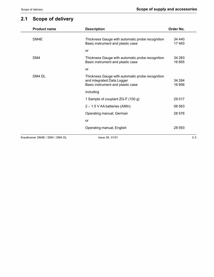
2.1 Scope of delivery
Product name Description Order No.
DM4E Thickness Gauge with automatic probe recognition 34 440Basic instrument and plastic case 17 493
or
DM4 Thickness Gauge with automatic probe recognition 34 283Basic instrument and plastic case 16 855
or
DM4 DL Thickness Gauge with automatic probe recognitionand integrated Data Logger 34 284Basic instrument and plastic case 16 856
including
1 Sample of couplant ZG-F (100 g) 29 017
2 � 1.5 V AA batteries (AlMn) 06 563
Operating manual, German 28 576
or
Operating manual, English 28 593
2-4 Issue 05, 01/01 Krautkramer DM4E / DM4 / DM4 DL
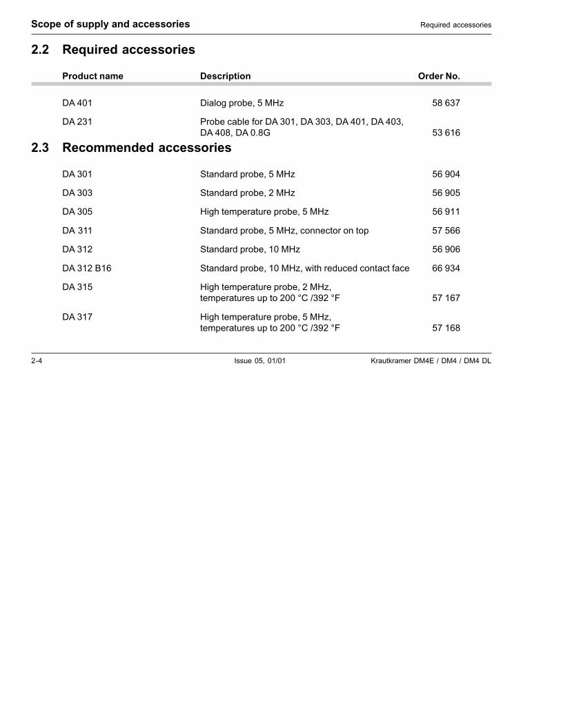
2.2 Required accessories
Product name Description Order No.
DA 401 Dialog probe, 5 MHz 58 637
DA 231 Probe cable for DA 301, DA 303, DA 401, DA 403,DA 408, DA 0.8G 53 616
2.3 Recommended accessories
DA 301 Standard probe, 5 MHz 56 904
DA 303 Standard probe, 2 MHz 56 905
DA 305 High temperature probe, 5 MHz 56 911
DA 311 Standard probe, 5 MHz, connector on top 57 566
DA 312 Standard probe, 10 MHz 56 906
DA 312 B16 Standard probe, 10 MHz, with reduced contact face 66 934
DA 315 High temperature probe, 2 MHz,temperatures up to 200 °C /392 °F 57 167
DA 317 High temperature probe, 5 MHz,temperatures up to 200 °C /392 °F 57 168
Scope of supply and accessories Required accessories
Krautkramer DM4E / DM4 / DM4 DL Issue 05, 01/01 2-5
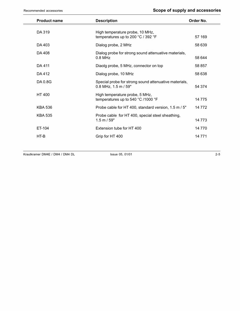
Product name Description Order No.
DA 319 High temperature probe, 10 MHz,temperatures up to 200 °C / 392 °F 57 169
DA 403 Dialog probe, 2 MHz 58 639
DA 408 Dialog probe for strong sound attenuative materials,0.8 MHz 58 644
DA 411 Diaolg probe, 5 MHz, connector on top 58 857
DA 412 Dialog probe, 10 MHz 58 638
DA 0.8G Special probe for strong sound attenuative materials,0.8 MHz, 1.5 m / 59" 54 374
HT 400 High temperature probe, 5 MHz,temperatures up to 540 °C /1000 °F 14 775
KBA 536 Probe cable for HT 400, standard version, 1.5 m / 5" 14 772
KBA 535 Probe cable for HT 400, special steel sheathing,1.5 m / 59" 14 773
ET-104 Extension tube for HT 400 14 770
HT-B Grip for HT 400 14 771
Recommended accessories Scope of supply and accessories
2-6 Issue 05, 01/01 Krautkramer DM4E / DM4 / DM4 DL
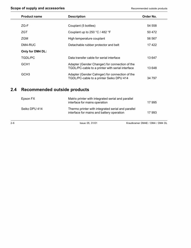
Product name Description Order No.
ZG-F Couplant (5 bottles) 54 558
ZGT Couplant up to 250 °C / 482 °F 50 472
ZGM High temperature couplant 56 567
DM4-RUC Detachable rubber protector and belt 17 422
Only for DM4 DL:
TGDL/PC Data transfer cable for serial interface 13 647
GCH1 Adapter (Gender Changer) for connection of theTGDL/PC-cable to a printer with serial interface 13 648
GCH3 Adapter (Gender Cahnger) for connection of theTGDL/PC-cable to a printer Seiko DPU 414 34 797
2.4 Recommended outside products
Epson FX Matrix printer with integrated serial and parallelinterface for mains operation 17 995
Seiko DPU 414 Thermo printer with integrated serial and parallelinterface for mains and battery operation 17 993
Scope of supply and accessories Recommended outside products
Krautkramer DM4E / DM4 / DM4 DL Issue 05, 01/01 3-1
Preparation for operation 3
3-2 Issue 05, 01/01 Krautkramer DM4E / DM4 / DM4 DL
3.1 Battery supply
DM4 instruments are operated with two non-recharge-able dry cells (AlMn, type AA). These are contained inthe delivery.
� Attention:
Only use batteries supplied by us or batteries havingthe same high performance data. Leaking batteriescan destroy the instrument!
� Note:
Take the batteries out of the instrument if you are notgoing to use it for a longer period.
The following symbol appears on the screen when thebattery voltage is too low.
�
Exchange the batteries immediately in this case. If thebattery voltage is too low, the instrument is automati-cally switched off in order to ensure a reliable opera-tion only if the batteries are sufficiently charged.
Preparation for operation Battery supply
All settings and stored measurement readings areretained and are immediately available.
Take a set of spare batteries if you carry out on-sitemeasurements.
� Note:
Used or defective batteries are special refuse andmust be disposed of according to statutory regula-tions!
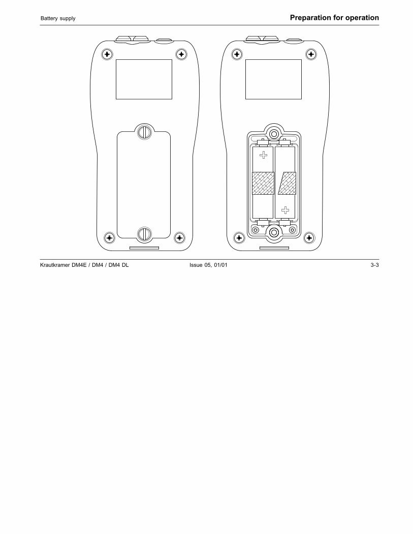
Inserting batteries
– Loosen both screws on the battery cover (on therear side of the instrument) and remove it.
– Place the two AlMn batteries into the battery com-partment. Make certain that the poles are thecorrect way round.
– Replace the cover and tighten the screws.
Krautkramer DM4E / DM4 / DM4 DL Issue 05, 01/01 3-3
Battery supply Preparation for operation
3-4 Issue 05, 01/01 Krautkramer DM4E / DM4 / DM4 DL
Preparation for operation Connecting the probe
3.2 Connecting the probe
In order to prepare the DM4 for operation you mustconnect the probe.
Select a probe which is suitable for your application.
Connect the probe cable to the socket on the top ofthe instrument. Make certain that the “nose” of thecable plug is completely seated into the round cavityon the connection socket.
Krautkramer DM4E / DM4 / DM4 DL Issue 05, 01/01 4-1
Basics of operation 4
4-2 Issue 05, 01/01 Krautkramer DM4E / DM4 / DM4 DL
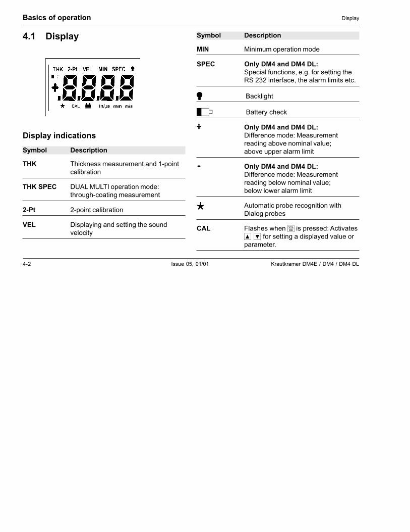
4.1 Display
Display indications
Symbol Description
THK Thickness measurement and 1-pointcalibration
THK SPEC DUAL MULTI operation mode:through-coating measurement
2-Pt 2-point calibration
VEL Displaying and setting the soundvelocity
Basics of operation Display
Symbol Description
MIN Minimum operation mode
SPEC Only DM4 and DM4 DL:Special functions, e.g. for setting theRS 232 interface, the alarm limits etc.
� Backlight
� Battery check
� Only DM4 and DM4 DL:Difference mode: Measurementreading above nominal value;above upper alarm limit
� Only DM4 and DM4 DL:Difference mode: Measurementreading below nominal value;below lower alarm limit
Automatic probe recognition withDialog probes
CAL Flashes when � is pressed: Activates��� for setting a displayed value orparameter.
Krautkramer DM4E / DM4 / DM4 DL Issue 05, 01/01 4-3
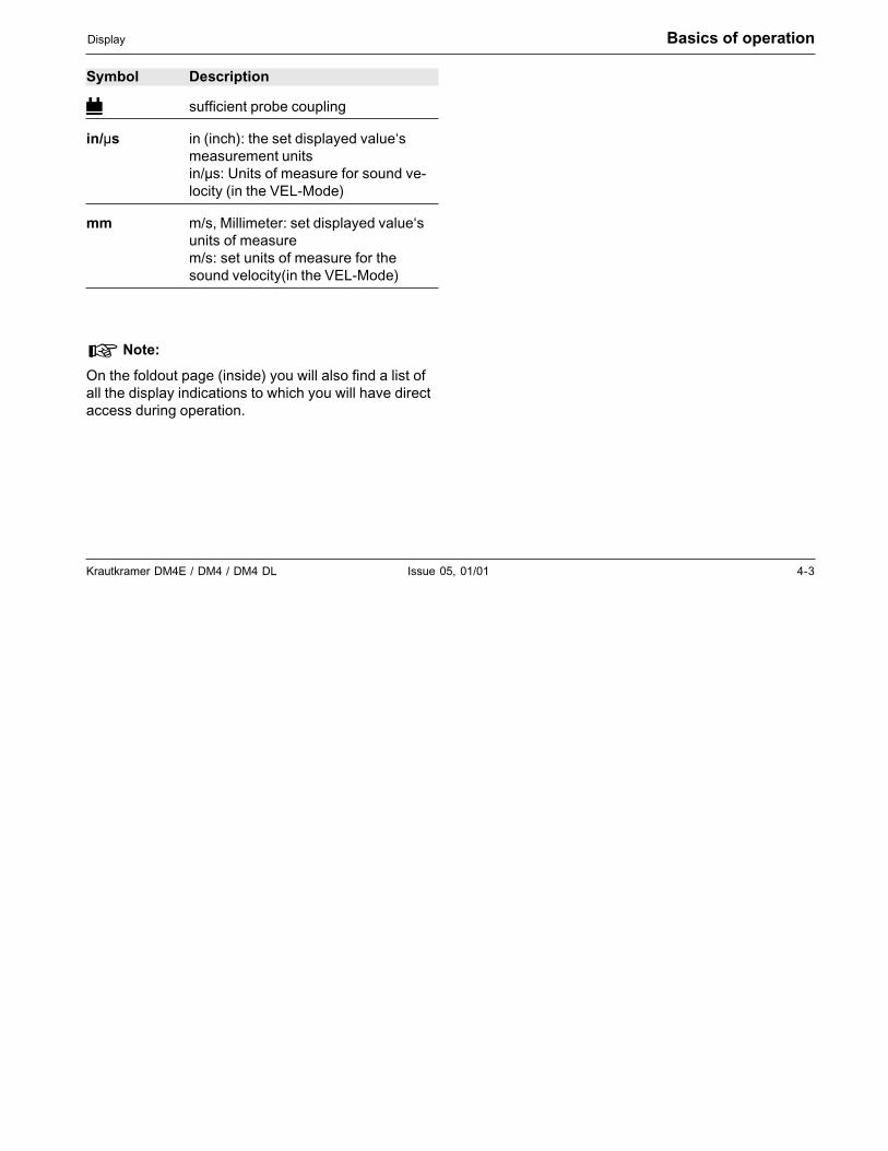
Display Basics of operation
Symbol Description
� sufficient probe coupling
in/µs in (inch): the set displayed value‘smeasurement unitsin/µs: Units of measure for sound ve-locity (in the VEL-Mode)
mm m/s, Millimeter: set displayed value‘sunits of measurem/s: set units of measure for thesound velocity(in the VEL-Mode)
� Note:
On the foldout page (inside) you will also find a list ofall the display indications to which you will have directaccess during operation.
4-4 Issue 05, 01/01 Krautkramer DM4E / DM4 / DM4 DL
Basics of operation Keys
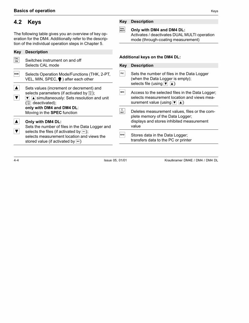
4.2 Keys
The following table gives you an overview of key op-eration for the DM4. Additionally refer to the descrip-tion of the individual operation steps in Chapter 5.
Key Description
� Switches instrument on and offSelects CAL mode
� Selects Operation Mode/Functions (THK, 2-PT,VEL, MIN, SPEC, �) after each other
� Sets values (increment or decrement) andselects parameters (if activated by �);
� ��� simultaneously: Sets resolution and unit(� deactivated);only with DM4 and DM4 DL:Moving in the SPEC function
� Only with DM4 DL:Sets the number of files in the Data Logger and
� selects the files (if activated by �);selects measurement location and views thestored value (if activated by �)
Key Description
� Only with DM4 and DM4 DL:Activates / deactivates DUAL MULTI operationmode (through-coating measurement)
Additional keys on the DM4 DL:
Key Description
� Sets the number of files in the Data Logger(when the Data Logger is empty);selects file (using ���)
� Access to the selected files in the Data Logger;selects measurement location and views mea-surement value (using ���)
� Deletes measurement values, files or the com-plete memory of the Data Logger;displays and stores inhibited measurementvalue
Stores data in the Data Logger;transfers data to the PC or printer
Krautkramer DM4E / DM4 / DM4 DL Issue 05, 01/01 4-5
Switching the instrument on and off Basics of operation
4.3 Switching the instrument onand off
Indications after switching on
– Press � to switch the instrument on.
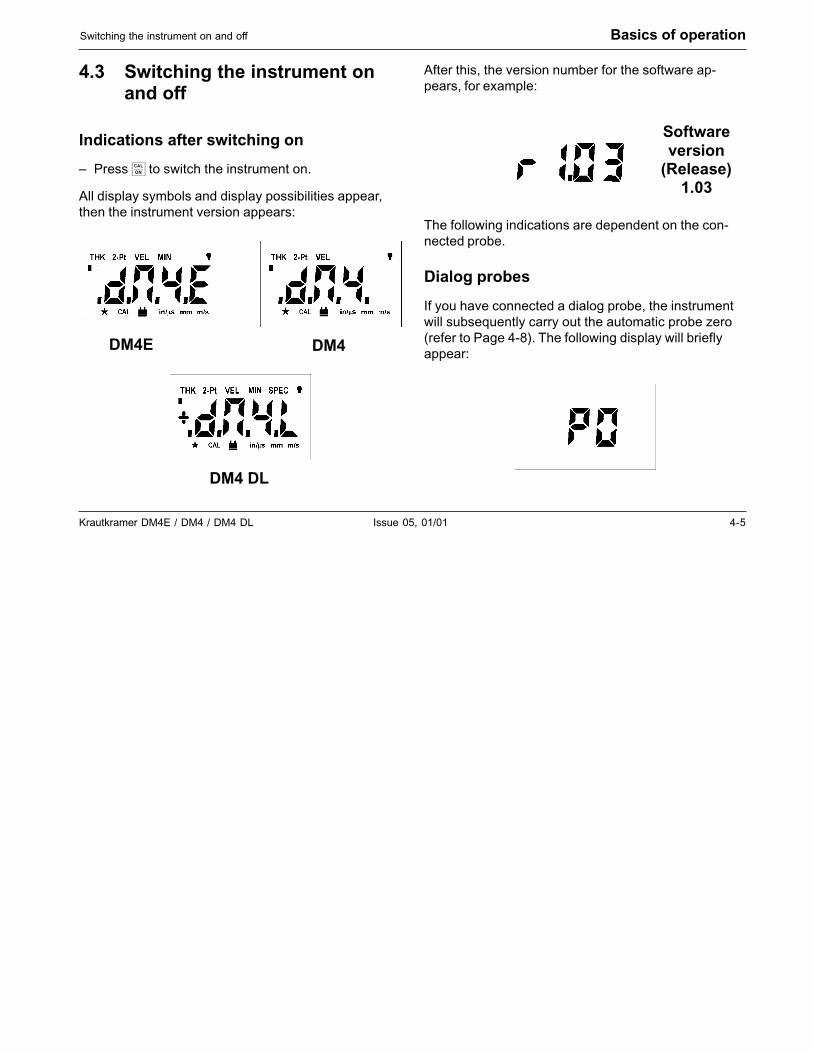
All display symbols and display possibilities appear,then the instrument version appears:
After this, the version number for the software ap-pears, for example:
The following indications are dependent on the con-nected probe.
Dialog probes
If you have connected a dialog probe, the instrumentwill subsequently carry out the automatic probe zero(refer to Page 4-8). The following display will brieflyappear:
Softwareversion
(Release)1.03
DM4E DM4
DM4 DL
4-6 Issue 05, 01/01 Krautkramer DM4E / DM4 / DM4 DL
Basics of operation Switching the instrument on and off
The display does not appear with active 2-point cali-bration (refer to Page 5-7).
After this, the probe type number is displayed (auto-matic probe recognition, refer to page 4-8). The instru-ment is then ready for measurement. With initial op-eration, the THK mode (thickness measurement)isdisplayed, otherwise the last setting which was set.
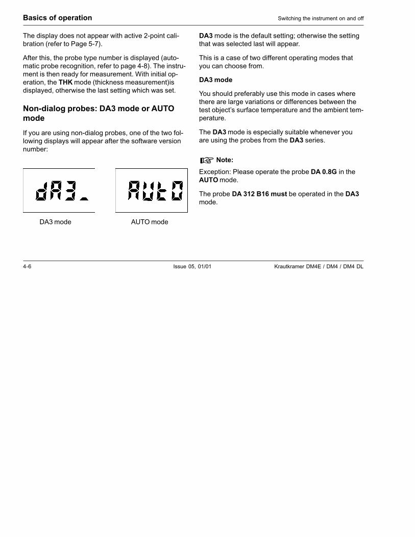
Non-dialog probes: DA3 mode or AUTOmode
If you are using non-dialog probes, one of the two fol-lowing displays will appear after the software versionnumber:
DA3 mode is the default setting; otherwise the settingthat was selected last will appear.
This is a case of two different operating modes thatyou can choose from.
DA3 mode
You should preferably use this mode in cases wherethere are large variations or differences between thetest object’s surface temperature and the ambient tem-perature.
The DA3 mode is especially suitable whenever youare using the probes from the DA3 series.
� Note:
Exception: Please operate the probe DA 0.8G in theAUTO mode.
The probe DA 312 B16 must be operated in the DA3mode.
DA3 mode AUTO mode
Krautkramer DM4E / DM4 / DM4 DL Issue 05, 01/01 4-7
Automatic instrument switch-off Basics of operation
Auto mode
The AUTO mode offers advantages with test objectshaving a rough sufrace and with probes showing con-siderable wear.
The two operating modes are always suitable for nor-mal applications.
Note:Due to improved sensitivity, HT400 probes require2-point calibration for best reading and accuracy.Use of the automatic zero feature could cause meas-meant inaccuracies of up to 0.2 mm (0.008").
Operation:
– The DA3 or AUTO display appears and flashes for 3seconds.
– Within this time, you can toggle between the twooperating modes using "mode" to select the requiredsetting.
– Just press a key to continue the operation using thedisplayed setting. Otherwise the instrument will takeover the setting after 3 seconds and switch tostand-by-mode.
– The selected setting is kept and also displayed nexttime the instrument is switched on or a probe isexchanged.
Switching the instrument off
You switch the instrument off by pressing "CAL" and keep-ing it pressed for about 3 seconds.
4.4 Automatic instrument switch-off
The DM4 has an automatic instrument switch-off.
This automatic switch-off activates if the instrumenthas not been used after 3 minutes (no key activation,no coupling or decoupling of the probe, no interfaceactivity with the DM4 DL).
By doing this, the current consumpution is decreasedand you do not waste any battery operation time.
4-8 Issue 05, 01/01 Krautkramer DM4E / DM4 / DM4 DL
Basics of operation Operation concept
4.5 Operation concept
� Note:
In the foldout you will find an overlook of operatinglevels enabling quick orientation.
Selecting operation modes/functions
Select the individual instrument operation modes/func-tions consecutively with �. The selected function willappear at the top of the display. The operation modes/functions available are dependent on the instrumentversion.
• THK
• 2-PT
• VEL
• MIN
• SPEC (DM4 and DM4 DL only)
• THK and SPEC (DM4 and DM4 DL only)
• �
After the last function �, the function THK appearswhen � is pressed.
Changing settings/values
For access to the corresponding setting possibilities ofselected functions press �.
The CAL indication below in the display flashes.
Using ��� you are able to change the settings.
Press � to store the settings.
Exception: SPEC
The SPEC menu has an additional operating levelwhich is directly accessible with ���.
Further functions appear whose settings are thenchanged as normal (press �, change with ��� andpress� again).
Krautkramer DM4E / DM4 / DM4 DL Issue 05, 01/01 4-9
Automatic probe zero adjustment Basics of operation
Accelerated setting
If, when setting, you have to span large ranges (e.g.when setting the sound velocity), you can acceleratethis:
– Press � or � and keep pressed.
The setting is accelerated.
4.6 Automatic probe zeroadjustment
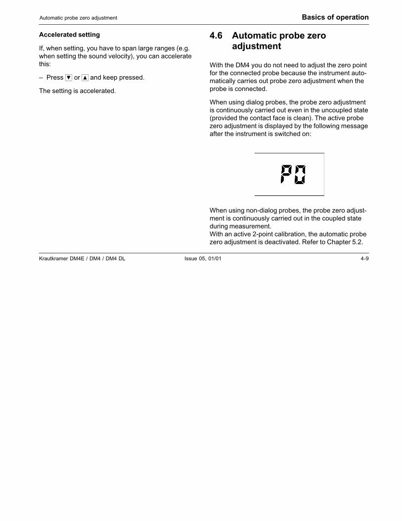
With the DM4 you do not need to adjust the zero pointfor the connected probe because the instrument auto-matically carries out probe zero adjustment when theprobe is connected.
When using dialog probes, the probe zero adjustmentis continuously carried out even in the uncoupled state(provided the contact face is clean). The active probezero adjustment is displayed by the following messageafter the instrument is switched on:
When using non-dialog probes, the probe zero adjust-ment is continuously carried out in the coupled stateduring measurement.With an active 2-point calibration, the automatic probezero adjustment is deactivated. Refer to Chapter 5.2.
4-10 Issue 05, 01/01 Krautkramer DM4E / DM4 / DM4 DL
Basics of operation Automatic probe zero adjustment
4.7 Automatic probe recognition
When you work with one of our DIALOG probes, thecorrection data stored in the corresponding probe isautomatically recognized. By doing this, a higher mea-surement accuracy is achieved as well as an optimumsetting and DM4 performance.
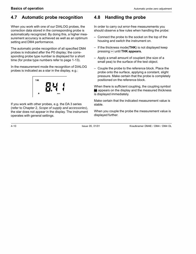
The automatic probe recognition of all specified DM4probes is indicated after the P0 display; the corre-sponding probe type number is displayed for a shorttime (for probe type numbers refer to page 1-13).
In the measurement mode the recognition of DIALOGprobes is indicated as a star in the display, e.g.:
If you work with other probes, e.g. the DA 3 series(refer to Chapter 2, Scope of supply and accessories),the star does not appear in the display. The instrumentoperates with general settings.
4.8 Handling the probe
In order to carry out error-free measurements youshould observe a few rules when handling the probe:
– Connect the probe to the socket on the top of thehousing and switch the instrument on.
– If the thickness mode(THK) is not displayed keeppressing� until THK appears.
– Apply a small amount of couplant (the size of asmall pea) to the surface of the test object.
– Couple the probe to the reference block. Place theprobe onto the surface, applying a constant, slightpressure. Make certain that the probe is completelypositioned on the reference block.
When there is sufficient coupling, the coupling symbol appears on the display and the measured thicknessis displayed immediately.
Make certain that the indicated measurement value isstable.
When you couple the probe the measurement value isdisplayed further.

Krautkramer DM4E / DM4 / DM4 DL Issue 05, 01/01 5-1
Operation 5
5-2 Issue 05, 01/01 Krautkramer DM4E / DM4 / DM4 DL
5.1 Basic settings
Setting the display backlight
You can switch the display backlight on and off. Youcan also select an automatic backlight. With this, thedisplay backlight is switched on when you couple theprobe or when a key is pressed. The display blanks 5seconds after the last instrument activation.
Operation:
– Keep pressing ��until� is displayed.
– Press �.
– Select the required setting with ����������
– Press � again to exit the function.
The selected setting is retained when you switch theinstrument off.
Operation Basic settings
Setting the units of measure and resolution
You can determine which units of measure you wish touse as well as the resolution of your instrument.
Units of measure: Millimeter or Inch
Resolution: 0.01 mm 0.001 in0.1 mm 0.01 in
Operation:
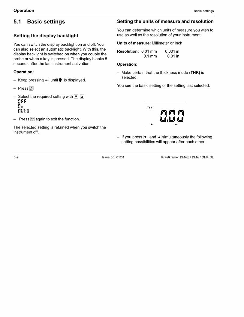
– Make certain that the thickness mode (THK) isselected.
You see the basic setting or the setting last selected:
– If you press ��and� simultaneously the followingsetting possibilities will appear after each other:
Krautkramer DM4E / DM4 / DM4 DL Issue 05, 01/01 5-3
Basic settings Operation
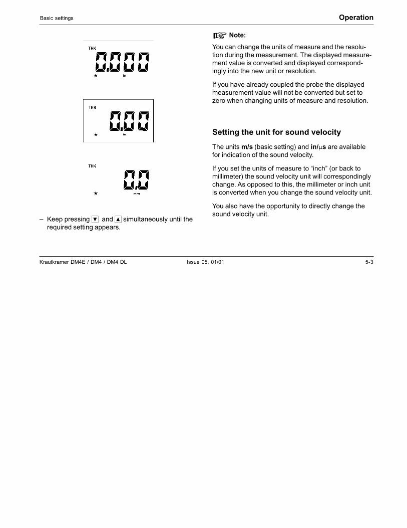
– Keep pressing ��and� simultaneously until therequired setting appears.
� Note:
You can change the units of measure and the resolu-tion during the measurement. The displayed measure-ment value is converted and displayed correspond-ingly into the new unit or resolution.
If you have already coupled the probe the displayedmeasurement value will not be converted but set tozero when changing units of measure and resolution.
Setting the unit for sound velocity
The units m/s (basic setting) and in/�s are availablefor indication of the sound velocity.
If you set the units of measure to “inch” (or back tomillimeter) the sound velocity unit will correspondinglychange. As opposed to this, the millimeter or inch unitis converted when you change the sound velocity unit.
You also have the opportunity to directly change thesound velocity unit.
5-4 Issue 05, 01/01 Krautkramer DM4E / DM4 / DM4 DL
Operation Calibrating the instrument
– Press � until the function VEL is displayed.
– Simultaneously press ���.
The unit is switched over. The displayed value is con-verted.
5.2 Calibrating the instrument
Before you are able to measure the thickness youmust calibrate the instrument on the material to betested.
You have the following possibilities:
• Sound velocity of the material is known; 1-pointcalibration is automatically carried out
• Sound velolcity is unknown; 1-point calibration witha calibration block of known thickness
• 2-point calibration with precision measurementswithin a narrow thickness range using a calibratonblock having two known thickness steps (or twocorresponding calibration blocks).
� Note:
You need not calibrate the instrument to the connectedprobe because the instrument automatically carriesout a zero point compensation. This applies to alltypes of probes in Chapter 2, Scope of supply andaccessories.
Krautkramer DM4E / DM4 / DM4 DL Issue 05, 01/01 5-5
Calibrating the instrument Operation
Calibration with a known sound velocity
When the sound velocity of a material is known thenyou only need enter it. A 1-point calibration will auto-matically be carried out.
You can then quickly carry out a measurement.
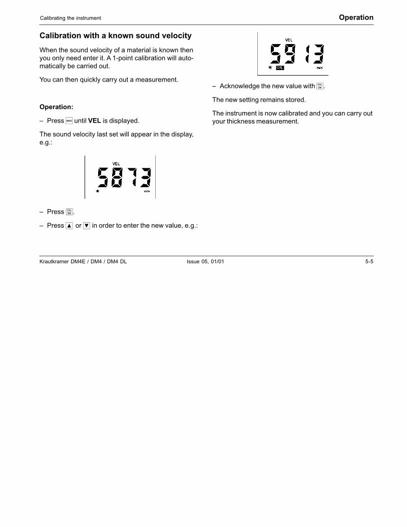
Operation:
– Press � until VEL is displayed.
The sound velocity last set will appear in the display,e.g.:
– Press �.
– Press ��or� in order to enter the new value, e.g.:
– Acknowledge the new value with �.
The new setting remains stored.
The instrument is now calibrated and you can carry outyour thickness measurement.
5-6 Issue 05, 01/01 Krautkramer DM4E / DM4 / DM4 DL
Operation Calibrating the instrument
1-point calibration
If the sound velocity is known or if you wish to checkcalibration, carry out a 1-point calibration.
For this you need a calibration block having a knownthickness and made of the same material as the testobject
� Note:
1-point calibration can only be carried out when the2-point calibration is switched off.
Operation:
– Make certain that the thickenss mode (THK) isdisplayed.
– Press �.
CAL flashes:
– Couple the probe to the calibration block and makecertain that the coupling symbol appears.
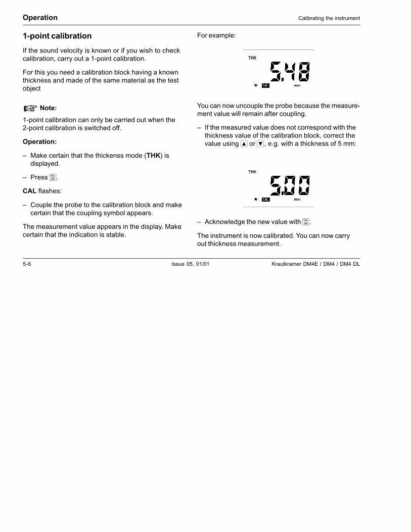
The measurement value appears in the display. Makecertain that the indication is stable.
For example:
You can now uncouple the probe because the measure-ment value will remain after coupling.
– If the measured value does not correspond with thethickness value of the calibration block, correct thevalue using � or �, e.g. with a thickness of 5 mm:
– Acknowledge the new value with �.
The instrument is now calibrated. You can now carryout thickness measurement.
Krautkramer DM4E / DM4 / DM4 DL Issue 05, 01/01 5-7
Calibrating the instrument Operation
2-point calibration
The 2-point calibration enables you to carry out anaccurate calibration. You should carry out this type ofcalibration when you are required to carry out mea-surements within a narrow thickness range.
You require a calibration block having two differentthicknesses (or two calibration blocks) which approxi-mately correspond to the upper and lower limits of thethickness range to be measured.
Operation:
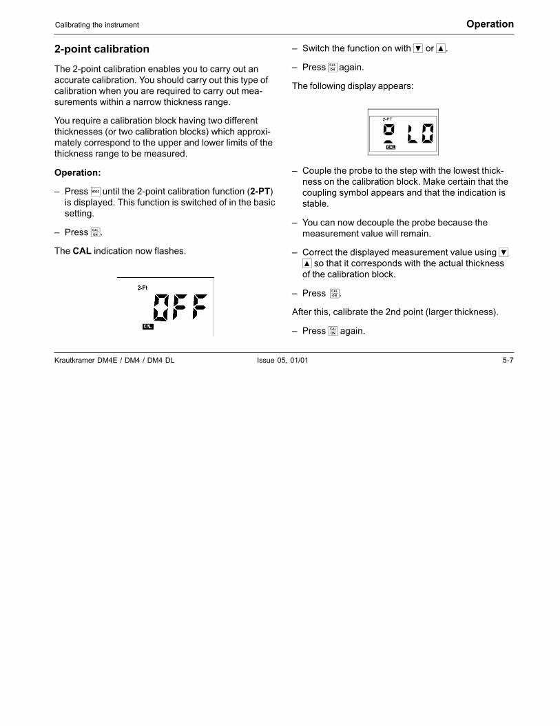
– Press � until the 2-point calibration function (2-PT)is displayed. This function is switched of in the basicsetting.
– Press �.
The CAL indication now flashes.
– Switch the function on with � or �.
– Press � again.
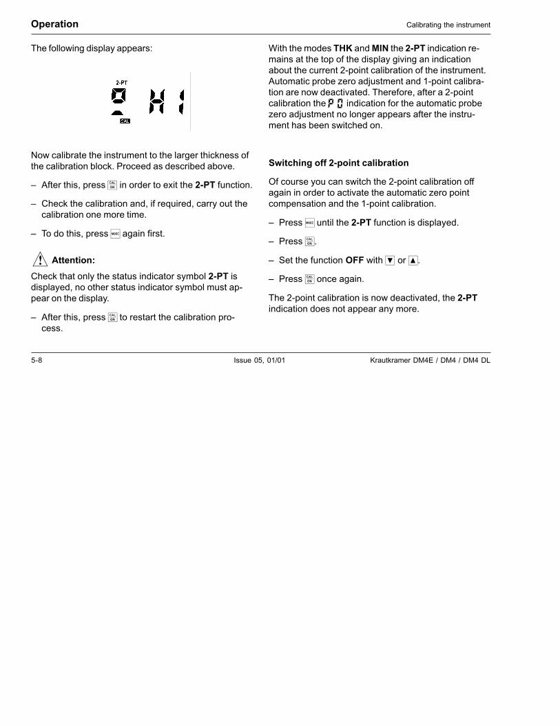
The following display appears:
– Couple the probe to the step with the lowest thick-ness on the calibration block. Make certain that thecoupling symbol appears and that the indication isstable.
– You can now decouple the probe because themeasurement value will remain.
– Correct the displayed measurement value using �� so that it corresponds with the actual thicknessof the calibration block.
– Press��.
After this, calibrate the 2nd point (larger thickness).
– Press � again.
5-8 Issue 05, 01/01 Krautkramer DM4E / DM4 / DM4 DL
Operation Calibrating the instrument
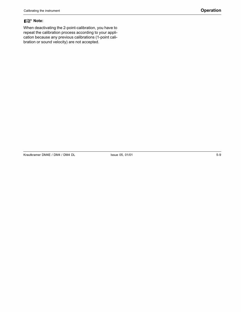
The following display appears:
Now calibrate the instrument to the larger thickness ofthe calibration block. Proceed as described above.
– After this, press � in order to exit the 2-PT function.
– Check the calibration and, if required, carry out thecalibration one more time.
– To do this, press � again first.
� Attention:
Check that only the status indicator symbol 2-PT isdisplayed, no other status indicator symbol must ap-pear on the display.
– After this, press � to restart the calibration pro-cess.
With the modes THK and MIN the 2-PT indication re-mains at the top of the display giving an indicationabout the current 2-point calibration of the instrument.Automatic probe zero adjustment and 1-point calibra-tion are now deactivated. Therefore, after a 2-pointcalibration the � indication for the automatic probezero adjustment no longer appears after the instru-ment has been switched on.
Switching off 2-point calibration
Of course you can switch the 2-point calibration offagain in order to activate the automatic zero pointcompensation and the 1-point calibration.
– Press � until the 2-PT function is displayed.
– Press �.
– Set the function OFF with � or �.
– Press � once again.
The 2-point calibration is now deactivated, the 2-PTindication does not appear any more.
Krautkramer DM4E / DM4 / DM4 DL Issue 05, 01/01 5-9
Calibrating the instrument Operation
� Note:
When deactivating the 2-point-calibration, you have torepeat the calibration process according to your appli-cation because any previous calibrations (1-point cali-bration or sound velocity) are not accepted.

5-10 Issue 05, 01/01 Krautkramer DM4E / DM4 / DM4 DL
Operation Thickness measurement
5.3 Thickness measurement
Standard measurement: THK mode
The following description of the thickness measure-ment applies to test objects whose surface tempera-ture corresponds to the ambient temperature. If yourequire to carry out measurements on hot surfacesrefer to Chapter 11.1 Application information.
If you want to carry out measurements through coat-ings, use the operating mode DUAL MULTI (pleaserefer to page 5-16).
Operation:
Make certain that the instrument is switched on and iscalibrated to the selected probe and the material to bemeasured (refer to Chapter 5.2 Calibrating the instru-ment).
If you require to work with alarm limits (only DM4 andDM4 DL) read the procedure in Chapter 5.4, Page5-13.
Make certain that the surface of the material is free ofdirt, remains of paint etc. and then apply a thin layer ofcouplant onto the surface of the material.
– Select the THK mode (if necessary press �).
– Place the probe carefully but firmly onto the surfaceof the material. Apply a constant pressure in orderto obtain a stable measurement value.
The coupling symbol � appears when there is suffi-cient coupling. At the same time the thickness readingis displayed, e.g.:
– You can now couple the probe.
The coupling symbol blanks. The displayed measure-ment value is retained.
Krautkramer DM4E / DM4 / DM4 DL Issue 05, 01/01 5-11
Thickness measurement Operation
Minimum capture measurement - MIN mode
The MIN mode is suitable for determining the smallestmeasurement value within a series of measurementsor within a rapid measurement sequence. The thick-ness measurement is made in this mode with an in-creased pulse repetition frequency in order to guaran-tee the reliable capture of the smallest measurementvalues during movement of the probe over the surfaceof the material.
When the probe is coupled, the smallest thicknessvalue of the measurement sequence is displayed. Themeasurement sequence finishes after a certain “time-out” (adjustable). The measurement sequence contin-ues when you position the probe again within the time-out. You determine the possible “breaks” in your mea-surement sequence by adjustment of the time-out.
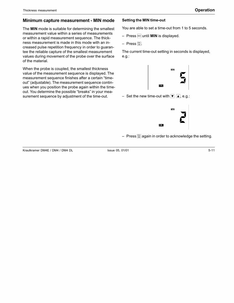
Setting the MIN time-out
You are able to set a time-out from 1 to 5 seconds.
– Press � until MIN is displayed.
– Press �.
The current time-out setting in seconds is displayed,e.g.:
– Set the new time-out with ���, e.g.:
– Press � again in order to acknowledge the setting.
5-12 Issue 05, 01/01 Krautkramer DM4E / DM4 / DM4 DL
Operation Thickness measurement
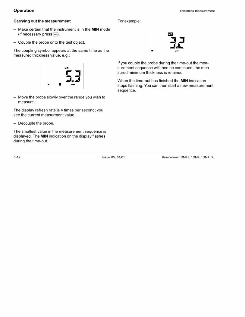
Carrying out the measurement
– Make certain that the instrument is in the MIN mode(if necessary press �).
– Couple the probe onto the test object.
The coupling symbol appears at the same time as themeasured thickness value, e.g.:
– Move the probe slowly over the range you wish tomeasure.
The display refresh rate is 4 times per second; yousee the current measurment value.
– Decouple the probe.
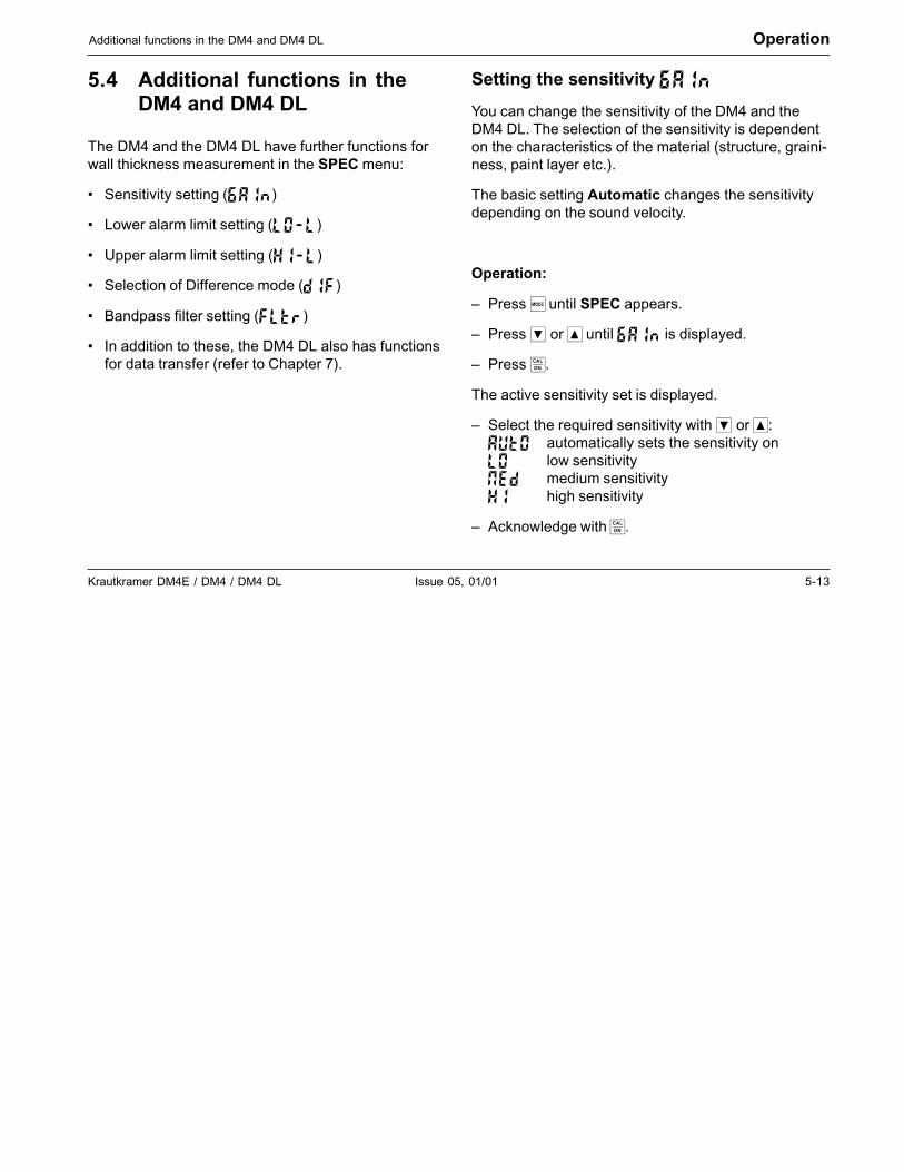
The smallest value in the measurement sequence isdisplayed. The MIN indication on the display flashesduring the time-out.
For example:
If you couple the probe during the time-out the mea-surement sequence will then be continued; the mea-sured minimum thickness is retained.
When the time-out has finished the MIN indicationstops flashing. You can then start a new measurementsequence.
Krautkramer DM4E / DM4 / DM4 DL Issue 05, 01/01 5-13
Additional functions in the DM4 and DM4 DL Operation
5.4 Additional functions in theDM4 and DM4 DL
The DM4 and the DM4 DL have further functions forwall thickness measurement in the SPEC menu:
• Sensitivity setting (��)
• Lower alarm limit setting (����)
• Upper alarm limit setting (����)
• Selection of Difference mode (���)
• Bandpass filter setting (����)
• In addition to these, the DM4 DL also has functionsfor data transfer (refer to Chapter 7).
Setting the sensitivity ����
You can change the sensitivity of the DM4 and theDM4 DL. The selection of the sensitivity is dependenton the characteristics of the material (structure, graini-ness, paint layer etc.).
The basic setting Automatic changes the sensitivitydepending on the sound velocity.
Operation:
– Press � until SPEC appears.
– Press � or � until �� is displayed.
– Press �.
The active sensitivity set is displayed.
– Select the required sensitivity with � or �:��� automatically sets the sensitivity on�� low sensitivity��� medium sensitivity�� high sensitivity
– Acknowledge with �.
5-14 Issue 05, 01/01 Krautkramer DM4E / DM4 / DM4 DL
Operation Additional functions in the DM4 and DM4 DL
Setting the alarm limits
�Attention:
When a Data Logger is active whilst changing thealarm limits, the previously stored settings are over-written.
You can set an upper and a lower alarm limit. If a mea-surement value goes above or falls below the limit, ared LED lights on the front panel of the instrument.
In addition to this, the � symbol appears before thevalue of an over-limit condition and a � before a valuewith an under-limit condition.
Operation:
– Press ��until SPEC appears in the display.
– Press ��or�� until ���� or ���� is displayed.
– Press �.
The active setting is displayed (basic setting: ���).
– Press ��or� in order to switch on the correspond-ing alarm limit.
– Press � again.
The active limit value set is displayed.
Basic setting:����� 500 mm����� 0.5 mm
– Set the required limit value with ��or �.There is an adjustment range available from 0.5 to500 mm. In doing this, the lower limit must not bethe same or larger than the upper limit value.
– Press��.
The set alarm limit is stored.
– Press � in order to return to thickness measure-ment.
Krautkramer DM4E / DM4 / DM4 DL Issue 05, 01/01 5-15
Additional functions in the DM4 and DM4 DL Operation
Switching the alarm off again
– Press ��until SPEC is displayed.
– Press ��or���until ���� or����� is displayed.
– Press �.
– Switch the corresponding function to ��� using �or��.
– Acknowledge with �.
The corresponding alarm limit is switched off.
Difference mode: ���
In the Difference mode the measured thickness iscompared with an adjustable nominal value.The difference is displayed.
Operation:
– Press���until SPEC is displayed.
– Press���or���until DIF appears.
– Press��.
The active setting appears (basic setting: ���).
– Press���or���in order to switch on the Differencemode.
– Press��.
You will see the active nominal value which is set.
– Set the required nominal value with���or��.
– Press���again.
– Press���until you are in the Standard mode again.
5-16 Issue 05, 01/01 Krautkramer DM4E / DM4 / DM4 DL
Operation Additional functions in the DM4 and DM4 DL
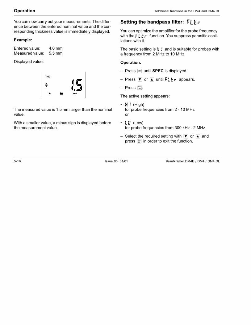
You can now carry out your measurements. The differ-ence between the entered nominal value and the cor-responding thickness value is immediately displayed.
Example:
Entered value: 4.0 mmMeasured value: 5.5 mm
Displayed value:
The measured value is 1.5 mm larger than the nominalvalue.
With a smaller value, a minus sign is displayed beforethe measurement value.
Setting the bandpass filter: ���
You can optimize the amplifier for the probe frequencywith the �����function. You suppress parasitic oscil-lations with it.
The basic setting is ���and is suitable for probes witha frequency from 2 MHz to 10 MHz.
Operation.
– Press���until SPEC is displayed.
– Press���or���until �����appears.
– Press��.
The active setting appears:
• ���(High)for probe frequencies from 2 - 10 MHzor
• ���(Low)for probe frequencies from 300 kHz - 2 MHz.
– Select the required setting with���or���andpress���in order to exit the function.
Krautkramer DM4E / DM4 / DM4 DL Issue 05, 01/01 5-17
Additional functions in the DM4 and DM4 DL Operation
Measuring through coatings:operating mode DUAL MULTI
With their operating mode DUAL MULTI, DM4 andDM4 DL offer you the possibility of acurately measur-ing the metal wall thickness under adherent coatings(paint coatings, plastic coatings, fiber-reinforced plas-tic sheathings, etc.).
If such a coating is not taken into account in the wallthickness measurement, the result may be consider-able measurement errors depending on the coatingthickness.
The operating mode DUAL MULTI avoids these mea-surement errors without removing the coating by al-lowing the measurement between two adjacentbackwall echoes.
� Note:
It is irrelevant for the operating mode DUAL MULTIwether you choose the DA3 or the AUTO mode.
The following standard probes are suitable for the op-erating mode DUAL MULTI:
• DA 301 DA 401
• DA 311 DA 411
• DA 312 DA 412
• DA 312 B16
• DA 317
• DA 319
The measuring range of the probes depends on thetype and thickness of the coating, thickness of themetal, and the quality of the bonding between metaland coating.
Operation:
– Make sure that the instrument is switched on andcalibrated to the selected probe and material to bemeasured (please refer to chapter 5.2 Calibratingthe instrument).
� Note:
You can carry out a 1-point calibration in DUAL MULTImode as well if two backwall echoes are measured onthe calibration block. To do this, switch the instrument
5-18 Issue 05, 01/01 Krautkramer DM4E / DM4 / DM4 DL
Operation Additional functions in the DM4 and DM4 DL
to DUAL MULTI mode (please see below) and thenproceed as described in 1-point calibration, page 5-6.
If you want to use alarm limits, please read the de-scription of the mode proceeding in chapter 5.4, page5-13.
– Activate the operating mode DUAL MULTI bypressing the��key.
– The display then shows the annunciators THK andSPEC.
� Note:
If you have connected a probe which is not suitable forthe operating mode DUAL MULTI ��is displayed.The display SPEC does not appear in this case.
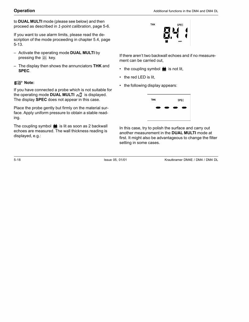
Place the probe gently but firmly on the material sur-face. Apply uniform pressure to obtain a stable read-ing.
The coupling symbol���is lit as soon as 2 backwallechoes are measured. The wall thickness reading isdisplayed, e.g.:
If there aren’t two backwall echoes and if no measure-ment can be carried out,
• the coupling symbol���is not lit,
• the red LED is lit,
• the following display appears:
In this case, try to polish the surface and carry outanother measurement in the DUAL MULTI mode atfirst. It might also be advantageous to change the filtersetting in some cases.
Krautkramer DM4E / DM4 / DM4 DL Issue 05, 01/01 5-19
Activating and deactivating functions Operation
If this does not lead to any success, carry out the wallthickness measurement in the standard mode, how-ever, you have to remove the coating from the testobject surface to do this.
– Deactivate the operating mode DUAL MULTI bypressing the �key again.
5.5 Activating and deactivatingfunctions
DM4 and DM4 DL offer you the possibility to configurefunctions: You can compile the function range of theinstrument as you require.
You can activate and deactivate the following func-tions:
• �� �: 2-point calibration
• ����: Bandpass filter setting (SPEC)
• ���: Difference mode (SPEC)
• ����: Upper alarm limit setting (SPEC)
• ����: Lower alarm limit setting (SPEC)
• ��: Sensitivity setting (SPEC)
• � ��: Complete SPEC menu
• ��: MIN mode
• ���: Display and adjustment of the soundvelocity
5-20 Issue 05, 01/01 Krautkramer DM4E / DM4 / DM4 DL
Operation Activating and deactivating functions
Operation:
Selecting the configuration level
The instrument is switched off.
– Switch on the instrument with���and keep��pressed.
– As soon as an indication appears additionally press�. Keep both keys pressed for about 3 seconds.
After switching on, the normal displays appear.
After this, the instrument switches into the functionfirst activated/deactivated (independent of which func-tion was last selected: basic setting: �� �).
Selecting functions
– Press���or���until the required function isdisplayed.
Function activation/deactivation
When the function is displayed which you wish to acti-vate or deactivate:
– Press��.
The active setting is displayed:
• ��= Function is activated.
• ����= Function is deactivated.
– Press���or �, in order to change the setting asrequired.
– Acknowledge with��.
The function which you have activated or deactivatedis displayed again.
– Carry out the same steps for all functions whosesetting you want to change.
– After this press �.
The instrument switches into the Standard mode.
All activated modes are indicated on the display.
� Note:
When functions are deactivated they are reset to theirbasic setting.
Krautkramer DM4E / DM4 / DM4 DL Issue 05, 01/01 6-1
Operation of the Data Logger (DM4 DL only) 6
6-2 Issue 05, 01/01 Krautkramer DM4E / DM4 / DM4 DL
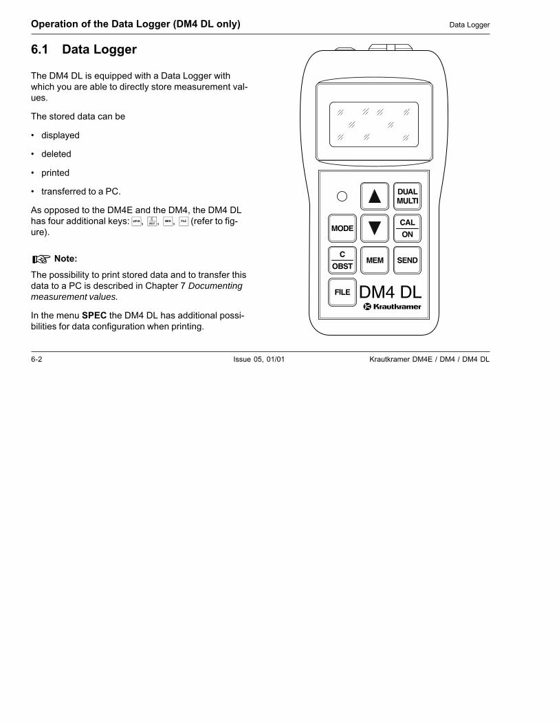
6.1 Data Logger
The DM4 DL is equipped with a Data Logger withwhich you are able to directly store measurement val-ues.
The stored data can be
• displayed
• deleted
• printed
• transferred to a PC.
As opposed to the DM4E and the DM4, the DM4 DLhas four additional keys: �,��,��,�� (refer to fig-ure).
� Note:
The possibility to print stored data and to transfer thisdata to a PC is described in Chapter 7 Documentingmeasurement values.
In the menu SPEC the DM4 DL has additional possi-bilities for data configuration when printing.
Operation of the Data Logger (DM4 DL only) Data Logger
Krautkramer DM4E / DM4 / DM4 DL Issue 05, 01/01 6-3
Setting the number of files Operation of the Data Logger (DM4 DL only)
The measurement values are combined into fileswhen stored. The number of measurement values perfile (file size) is automatically determined when youconfigure the Data Logger, i.e. determining the numberof files required (max. 999). The DM4 DL divides thetotal storage capacity of 5394 measurement values bythe determined number of files and applies the maxi-mum number of same sized files permitted by the ca-pacity.
The first measurement value is stored in each filestarting with memory location number 1. You can alsoselect another output location. The following measure-ment values are continually stored until all memorylocations are filled or if another file is selected for stor-age.
� Note:
The stored measurement values are retained evenwhen the batteries are taken out of the instrument.
We therefore recommend that you make a backup ofimportant data onto an external data carrier. Refer toChapter 7.2 Transferring data to a PC, Page 7-8.
6.2 Setting the number of files
Before you can store the measurement values with theData Logger you must determine the number of files.
The number of files depends on the number ofmemory locations required for each file. One memorylocation corresponds to one measurement value. De-pending on your application, determine the maximumnumber of measurement values which can be storedin a file. On the basis of the maximum file size, selectthe possible file number using the table in Chapter11.3.
You can only configure the Data Logger, i.e. setting thenumber of files, when the complete memory is empty.
Operation:
You are in a measurement mode (THK, THK/SPEC,MIN or DIF).
– Press��.

6-4 Issue 05, 01/01 Krautkramer DM4E / DM4 / DM4 DL
Operation of the Data Logger (DM4 DL only) Setting the number of files
The following display appears when the Data Loggeris empty:
� Note:
If the memory is not empty, the file number will bedisplayed (e.g.�����). In this case you must firstlyclear the memory. Refer to Page 6-12 of this chapter,Clearing the complete memory.
When �����appears you can then configure theData Logger.
– Press� �or���in order to enter the requirednumber of files, e.g.:
Example:
With a set number of 64 files you have 80 memorylocations available per file (refer to the table in Chapter11.3)
– Acknowledge with��.
The display ����appears for about 12 seconds.
The Data Logger configures the memory.
After this, the DM4 DL switches back to its selectedmeasurement mode. The Data Logger is now config-ured. You can store your measurement values.
Krautkramer DM4E / DM4 / DM4 DL Issue 05, 01/01 6-5
Storing the measurement values Operation of the Data Logger (DM4 DL only)
6.3 Storing the measurement values
In order to store measurement values, you must firstlyselect a file in which it is to be stored.
File selection
Operation:
You are in a measurement mode(THK, MIN or DIF).
– Press��.
The active file is displayed when the Data Logger isfirst used:
You will see the following information in addition to thefile number:
������ Empty file, contains no measurement value������� File which already contains measurement
values but is not full������ File full, cannot store further measurement
values.(��� = File number)
� Note:
– The Data Logger is not configurated when ����appears. Refer to Chater 6.2 Setting the number offiles.
Press� �or�, if you wish to select another file. Youmust select a file which has at least one free memorylocation.
� Note:
You can scroll through the existing files with��� .After selecting the highest file number with� �thedisplay ����� will appear (all files). You will need thissetting for clearing the files (refer to Page 6-12). After
6-6 Issue 05, 01/01 Krautkramer DM4E / DM4 / DM4 DL
Operation of the Data Logger (DM4 DL only) Storing the measurement values
this the display will jump back to file number 1. Thedisplay ����� will appear after selection of the small-est file number (1); after this, the display will jump tothe highest file number.
– When the required file is displayed, acknowledgewith��.
The active memory location number is briefly dis-played, i.e. the first free memory location (�����) ofthe selected file, e.g. when the file is empty:
That means the first measurement value on memorylocation number 1 is allocated.
After this, the DM4 DL switches back into the ready-for-measurement state.
Storing measurement values in the se-lected file
When you have selected a file in which there are freestorage locations, measurement values can be storedin the Data Logger.
You are able to store measurement values in all mea-surement modes. The following settings are stored:
• Diffence values in the ����mode
• Upper and lower alarm limits
• Probe data with dialog probes
Operation:
– Carry out your thickness measurement.
– When the measurement value which you wish tostore is displayed, press �.
The measurement value is stored in the selected file inthe Data Logger. The active memory location numberis briefly displayed, e.g. ����.
You can store the measurement values by pressing �until all memory locations are allocated.
Krautkramer DM4E / DM4 / DM4 DL Issue 05, 01/01 6-7
Storing the measurement values Operation of the Data Logger (DM4 DL only)
After a value has been stored in the Data Logger the� key remains inhibited until a new valid measure-ment. Zero values are not stored.
� Attention:
Make certain that all measurement values are storedwith the same resolution so that no errors occur withstatistical data in the report printout.
If you store the measurement values after each other����� will appear after the last memory location hasbeen allocated. When this happens, select a new fileor delete the stored measurement values (refer toChapter 6.5, Page 6-11).
� Note:
����� appears every time an attempt is made tostore a measurement value onto a memory locationwhich is already allocated. For selecting individualmemory locations, e.g. to see if empty locations areavailable in the file, refer to Page 6-8.
6-8 Issue 05, 01/01 Krautkramer DM4E / DM4 / DM4 DL
Operation of the Data Logger (DM4 DL only) Storing the measurement values
Inhibiting a memory location
You can inhibit a memory location and proceed to thenext location, for example when you are not able tomeasure a particular point within a measurement se-ries.
If needed, you can select the inhibited memory loca-tion later in order to store a measurement value there.The inhibited memory location is simply overwritten.
Operation:
You are in the mode THK, THK/SPEC or MIN andhave activated a file in which you wish to store yourvalues.
– Uncouple the probe.
– Press��.
As usual the memory location number will be brieflydisplayed, e.g. �����. Finally �����(obstruct) willappear.
The memory location is inhibited.
– Simply carry out your next measurement.
The DM4 DL automatically stores the next measure-ment value into the next memory location.
Selecting a memory location
You can individually select memory locations at whichthe next measurement value is to be stored if, for ex-ample, you overwrite an inhibited measurement value.
Operation:
You are in the mode THK, THK/SPEC or MIN:
– Press��.
The active memory location number is displayed, e.g.������.
Whereby:
������ = memory location allocated
������ = memory location empty
Krautkramer DM4E / DM4 / DM4 DL Issue 05, 01/01 6-9
Viewing stored measurement values Operation of the Data Logger (DM4 DL only)
– With���or� �you can select the memory locationat which the next measurement value is to bestored.
– Press���twice.
The instrument again switches to the ready-for-mea-surement state. The selected memory location is ac-tive.
� Note:
The following chapter describes how you display indi-vidual measurement values contained in the memorylocations.
6.4 Viewing stored measurementvalues
You can have your measurement values in the DataLogger displayed.
Operation:
– If necessary, select the file whose measurementvalues you wish to see (refer to Page 6-5).
You are in the THK, THK/SPEC or MIN mode.
– Press��.
The active memory location number is displayed, e.g.�����.
– Press� �or���until the required memory locationappears.
– Press���again in order to display the storedmeasurement value.
The measurement value is displayed in the selectedunit of measure.
6-10 Issue 05, 01/01 Krautkramer DM4E / DM4 / DM4 DL
Operation of the Data Logger (DM4 DL only) Viewing stored measurement values
– Press� �or���in order to view other memorylocations.
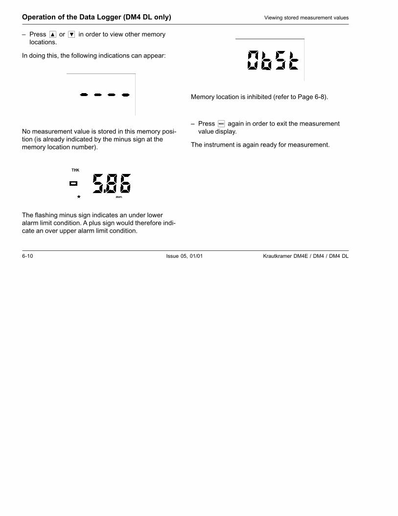
In doing this, the following indications can appear:
No measurement value is stored in this memory posi-tion (is already indicated by the minus sign at thememory location number).
The flashing minus sign indicates an under loweralarm limit condition. A plus sign would therefore indi-cate an over upper alarm limit condition.
Memory location is inhibited (refer to Page 6-8).
– Press���again in order to exit the measurementvalue display.
The instrument is again ready for measurement.
Krautkramer DM4E / DM4 / DM4 DL Issue 05, 01/01 6-11
Deleting stored measurement values Operation of the Data Logger (DM4 DL only)
6.5 Deleting stored measurementvalues
You can either delete individual measurement values,complete files or the total memory. Free memory loca-tions can be reallocated with new measurement val-ues after deleting individual measurement values.
Deleting and replacing individualmeasurement values
Operation:
– With���and��� �select the required file andpress���again.
– Press���and��� �in order to select the requiredmemory locations.
– Press���and then��� �until the measurementvalue you wish to delete is displayed.
– Press��.
A message appears briefly indicating deletion of themeasurement value (e.g. �����) and then the indica-tion for an empty memory location:
– Press���again in order to return to the measure-ment mode.
The measurement value is deleted. The new measure-ment value can now be filed into the empty memorylocation.
Deleting a file
� Attention:
When you delete a file, the data is irretrievably lost.Save your data beforehand on an external data carrier(refer to Chapter 7.2 Transferring data to a PC).
Operation:
– With���and��� �select the required file, e.g.�����.
– Press���and keep it pressed for about 3 seconds.
6-12 Issue 05, 01/01 Krautkramer DM4E / DM4 / DM4 DL
Operation of the Data Logger (DM4 DL only) Deleting stored measurement values
A message appears briefly indicating deletion of thefile (e.g. ����). Then the file number appears.A minus sign appears indicating that the file is empty,e.g.:
The selected file is deleted.
– With���return to the measurement mode or, using�� , select a new file which you wish to delete.
Clearing the complete memory
You can delete the complete memory, i.e. all files withall measurement values. For example, you must dothis when wishing to reconfigure the Data Logger.
� Attention:
When you delete a file, the data is irretrievably lost.Save your data beforehand on an external data carrier(refer to Chapter 7.2 Transferring data to a PC).
Operation:
– Press��.
– Press� �or���until ����� appears. This indica-tion appears at the beginning and at the end of thedata series, i.e. with� �to the highest available filenumber and with���to ����.
– Press���and keep pressed for about 3 seconds.
���� is displayed.
– Press���in order to return to the measurementmode.
The complete memory is cleared. No measurementvalues are stored until the Data Logger isreconfigured, i.e. the number of files determined.
Krautkramer DM4E / DM4 / DM4 DL Issue 05, 01/01 7-1
Documenting measurement values (DM4 DL only) 7
7-2 Issue 05, 01/01 Krautkramer DM4E / DM4 / DM4 DL
7.1 Printing data
In connection with a printer having a serial interface(e.g. Epson FX), the DM4 DL offers you the possibilityto print adjustment and measurement data as well asstatistical data.
In the DM4 DLs SPEC menu certain adjustments canbe carried out for printing the data:
���� Setting the data transfer rate
���� Language selection
� Selection of printer driver
��� Print “File header” with general data
� � Print statistical data
For printing your measurement report you need:
• A printer with serial interface RS 232
• A data cable TGDL/PC with adapter GCH1 forconnecting the DM4 DL to the printer Epson FX (orGCH3 for a printer Seiko DPU 414).
Documenting measurement values (DM4 DL only) Printing data
Preparing the printer
– Using the cable TGDL/PC, connect the printer tothe DM4 DL via the serial interface RS 232.
Data transfer for the DM4 DL is made in the followingdata format:
• Baud rate 9600 (basic setting)
• Data bits 8
• Stop bits 1
• Parity none
The baud rate is adjustable (refer to the followingpage); all other parameters are fixed.
Make certain that the settings of the printer corre-spond to whose of the DM4 DL.
Refer to the printer operating manual for informationabout setting the transfer parameters.
Krautkramer DM4E / DM4 / DM4 DL Issue 05, 01/01 7-3
Printing data Documenting measurement values (DM4 DL only)
Selecting the baud rate
With regard to data transfer, you will find the selectionof settings in the SPEC menu.
You can select the data transfer rate (baud rate) withwhich the data is sent to the printer or PC.
� Note:
The baud rate setting must correspond to the settingof the printer or PC.
Operation:
– Press���until SPEC is displayed.
– Press���or���until�����is displayed.
– Press �.
The active setting is displayed (basic setting 9600).
– Select a setting with���or��:
���� low speed������������ high speed
– Acknowledge with��.
You remain in the SPEC menu.
Selecting the report language
You can select the language in which your report isprinted or transferred to a PC.
Operation:
– Press���until SPEC is displayed.
– Press���or���until �����is displayed.
– Press��.
The previous setting is displayed.

7-4 Issue 05, 01/01 Krautkramer DM4E / DM4 / DM4 DL
Documenting measurement values (DM4 DL only) Printing data
– Select the required language with���or��:
�� English�� German��� Japanese���� Russian� �� Italian� Spanish��� French
– Acknowledge with��.
You remain in the SPEC menu.
� Note:
For a report printout in Japanese and Russian, theprinters used must be equipped with the correspond-ing character sets.
Selecting the printer driver
For printing or transfer of data, select the appropriateprinter driver.You have the following possibilities for printing data:EPSON FX 850 with serial interface; Seiko DPU 414.For data transfer to a PC, select the 24 column format
for importing the data into the DATAMATE program orthe spreadsheet format for importing the data intospreadsheet programs.
Operation:
– Press���until SPEC is displayed.
– Press���or���until ��is displayed.
– Press��.
The previous format is displayed.
– Select the report format with���or��:
� Epson printer�� DPU 411 printer���� 24 column format (DATAMATE)��� Spreadsheet program
– Acknowledge with��.
You remain in the SPEC menu.
Krautkramer DM4E / DM4 / DM4 DL Issue 05, 01/01 7-5
Printing data Documenting measurement values (DM4 DL only)
Selection of file header printout
You can determine whether a file header with generaldata be printed or not.
Operation:
– Press���until SPEC is displayed.
– Press���or���until ����is displayed.
– Press��.
The active setting is displayed.
– Select the required setting with���or��:
�� Printout of file header��� No printout of file header
– Acknowledge with��.
You remain in the SPEC menu.
Selection of statistics printout
You can select whether the report printout containsstatistical data or not.
Operation:
– Press���until SPEC is displayed.
– Press���or���until � � �is displayed.
– Press��.
The active setting is displayed.
– Select the required setting with���or��:
�� Printout of statistical data��� No printout of statistical data
– Acknowledge with��.
You remain in the SPEC menu.
7-6 Issue 05, 01/01 Krautkramer DM4E / DM4 / DM4 DL
Documenting measurement values (DM4 DL only) Printing data
Printing the measurement report
You can print individual files or the complete memorycontaining all files. Even an individual measurementreading can be printed.
The report printouts can be made with or without fileheader as well as statistical data, depending on thesetting in the SPEC menu.
Operation:
You are in the THK or DIF mode.
Printing all files
– Press� .
– Press���or���until �!��� is displayed.
– Press�".
�!��� appears on the display.
All files in the Data Logger are printed. Any empty filesor empty memory locations are not printed.
Printing individual files
– Print� .
– Press���or���until the required file is displayed,e.g. �!��#.
– Press�".
�!��# appears on the display.
The selected file is printed. Empty memory locationsare not printed.
After printing the stored data press f in order to returnto the measurement mode. All printed measurementdata remain in the DM4 DL memory.
Printing individual measurement readings
If a printer is connected you are able to directly print adisplayed measurement reading by simply pressing".
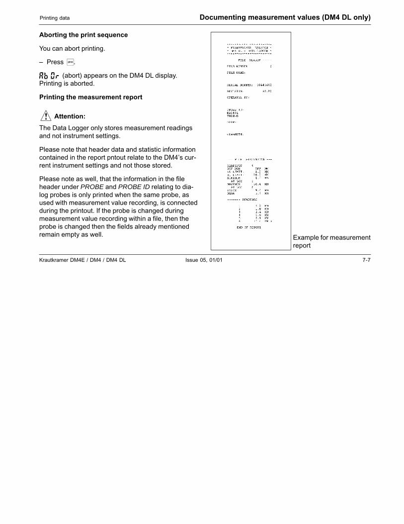
Krautkramer DM4E / DM4 / DM4 DL Issue 05, 01/01 7-7
Printing data Documenting measurement values (DM4 DL only)
Aborting the print sequence
You can abort printing.
– Press�".
���� (abort) appears on the DM4 DL display.Printing is aborted.
Printing the measurement report
� Attention:
The Data Logger only stores measurement readingsand not instrument settings.
Please note that header data and statistic informationcontained in the report pntout relate to the DM4’s cur-rent instrument settings and not those stored.
Please note as well, that the information in the fileheader under PROBE and PROBE ID relating to dia-log probes is only printed when the same probe, asused with measurement value recording, is connectedduring the printout. If the probe is changed duringmeasurement value recording within a file, then theprobe is changed then the fields already mentionedremain empty as well. Example for measurement
report
7-8 Issue 05, 01/01 Krautkramer DM4E / DM4 / DM4 DL
Documenting measurement values (DM4 DL only) Transferring data to a PC
7.2 Transferring data to a PC
You can transfer the stored measurement readings toa PC.
The data is transferred in ASCII format. For data trans-fer you will need a normal terminal program, such ascontained in Microsoft Windows. The data can then beprocessed in word processing, database and spread-sheet programs.
� Note:
User-friendly data transfer possibilities as well as sta-tistic and analysis functions are offered by specialuser-programs from Krautkrämer (e.g. GUS and MINI-MAX). Further information can be obtained fromKrautkrämer or from your local Krautkrämer represen-tative.
Connnecting a PC
The DM4 DL is switched off.
– Connect the DM4 DL to the PC using theKrautkrämer transfer cable TGDL/PC.
– If necessary check the interface settings (refer toPage 7-2).
Transferring data
Data transfer is made parallel to printer transfer. Onyour screen you receive the same report format asgiven for the printer. The adjustment possibilities arealso the same (language, file header, statistic).
Operation:
The DM4 DL is either in THK or DIF mode.
– Press� .
– Select the required measurement set with���or�.
Krautkramer DM4E / DM4 / DM4 DL Issue 05, 01/01 7-9
Transferring data to a PC Documenting measurement values (DM4 DL only)
� Note:
If you wish to transfer all measurement sets at once,select�!���.
– Press�".
The selected data are transferred to the PC.
– Press� .
You arrive back into the DM4 DLs active operationmode.
� Note:
Empty memory locations and empty measurementsets are not transferred.
The data is now available as ASCII files on your PCand can be further processed.
Transferring individual measurement values
When a PC is connected you are able to directly trans-fer a displayed measurement value by pressing�".
Transferring data for the spreadsheet program
You can transfer the data in a format which is able tobe directly imported into a spreadsheet program, e.g.LOTUS or Microsoft EXCEL.
� Note:
Refer to the manual for the spreadsheet program re-garding information about importing data.
– Select the format �����in the function �(refer to Page 7-4).
– Then proceed as normal with data transfer.
� Note:
The file header is always transferred with this format;the transfer of the statistics can be selected as nor-mal.
7-10 Issue 05, 01/01 Krautkramer DM4E / DM4 / DM4 DL
Documenting measurement values (DM4 DL only) Transferring data to a PC
Aborting transfer
You can abort the transfer sequence.
– Wait until the information in the file and the statisticis transferred.
– Press�".
���� (abort) appears on the DM4 DL display.Transfer is aborted.

Krautkramer DM4E / DM4 / DM4 DL Issue 05, 01/01 8-1
Care and maintenance 8
8-2 Issue 05, 01/01 Krautkramer DM4E / DM4 / DM4 DL
Care and maintenance Care
8.1 Care
Care of the instrument
Clean the instrument and accessories with a dampcloth. Use water or a mild household cleaner.
� Attention:
Never use solvents!The plastic parts could be damaged or become brittle.
Handling AlMn batteries
Due to the fact that wrong treatment of batteries couldcause damage to the instrument, please observe thefollowing tips:
– Only use leakproof batteries!
– Remove the batteries from the instrument when notbeing used over a long period!
� Note:
Used or defective batteries are special refuse andmust be disposed of in accordance with statutory pro-visions!
Krautkramer DM4E / DM4 / DM4 DL Issue 05, 01/01 8-3
Maintenance Care and maintenance
8.2 Maintenance
Basically, DM4 instruments do not require any mainte-nance.
� Attention:
Repair work my only be carried out by authorizedKrautkrämer service personnel.

8-4 Issue 05, 01/01 Krautkramer DM4E / DM4 / DM4 DL
Krautkramer DM4E / DM4 / DM4 DL Issue 05, 01/01 9-1
Specifications 9
9-2 Issue 05, 01/01 Krautkramer DM4E / DM4 / DM4 DL
Principle of operation Ultrasonic pulse echo method with T/R probes
Gain Automatic or manual; HI, MED or LOW (adjustable)
Zero adjustment Automatic; manual with 2-point calibration
Calibration 1-point calibration with set sound velocity, 2-point calibration, manually using thecalibration block (with 2 thicknesses) from the same material and with the samesound velocity as the material to be tested
V-path correction Automatic
Measurement range standard operation: 0.6 mm - 500 mm / 0.025 inch - 20.0 inch (in steel), dependingon the probe, material and surfaceDUAL MULTI operation: 2 mm - 25 mm (in steel), depending on the probe, materialand surface
Display resolution selectable for thicknesses up to 99.99 mm (9.999 inch):0.01 mm or 0.1 mm (0.001 inch or 0.01 inch)> 100.0 mm (10 inch): 0.1 mm (0.01 inch)
Units of measure Selectable: mm or inch
Sound velocity range 1000 - 9999 m/s (resolution 1 m/sec) / 39,000 - 393,700 inch/sec
Display 4 digit LCD with switchable backlight; digit height: 12.7 mm / 5 inch
Display frequency > 4 Hz
Measurement frequency 25 Hz in the MIN mode; 4 Hz in the THK mode
Specifications
Krautkramer DM4E / DM4 / DM4 DL Issue 05, 01/01 9-3
Specifications
Power supply 2 batteries (1.5 V AA)
Operating duration Up to 200 hours with dry cell batteries (without backlight)may be reduced depending on the operating mode
Automatic cutout After 3 minutes of non-use
Operating temperature -10° C to +50 °C / +10 °F to +120 °C
Keypad Dust and waterproof membrane keypad
Battery compartment Protected against dust and water spray
Housing Protected against shock, dust and water spray
Size 150 mm � 77 mm � 33 mm / 5.8 inch � 3.0 inch � 1.4 inch (L � W � D)
Weight 255 g / 9 oz. including batteries
Capacity of data logger 5390 measurement values, optionally divided in up to 999 files
Data interfaces TTL: serial, asynchronous, 0/+5 V, 8 bit, 1 stop-bit, 1200, 2400, 4800 and 9600Baud, no parityRS 232 C: bipolar logic with connection of a TGDL/PC cable

9-4 Issue 05, 01/01 Krautkramer DM4E / DM4 / DM4 DL

Krautkramer DM4E / DM4 / DM4 DL Issue 05, 01/01 10-1
Interfaces and peripherals 10
10-2 Issue 05, 01/01 Krautkramer DM4E / DM4 / DM4 DL
Interfaces and peripherals Interface RS 232
10.1 Interface RS 232
� Attention:
Only use the supplied special cable from Krautkrämerfor connecting peripheral equipment (printer, PC etc.).
This cable contains a special electronic circuit in theDB25 plug for level conversion.
If you wish to connect the transfer cable to instrumentswith 9 pin RS 232 interfaces, use the supplied adapter.
Data format
Physical data transfer via the DM4 DL’s RS 232 inter-face is made in the following data format:
• Baud rate,preset at the factory 9600
• Number of start bits 1
• Number of stop bits 1
• Number of data bits 8
• Parity none
Make certain that the transfer parameters of the con-nected equipment correspond to these settings.
� Note:
The automatic instrument cutout is deactivated duringthe data transfer sequence.
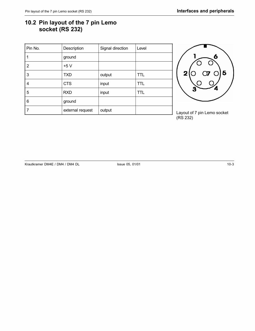
Krautkramer DM4E / DM4 / DM4 DL Issue 05, 01/01 10-3
Pin layout of the 7 pin Lemo socket (RS 232) Interfaces and peripherals
10.2 Pin layout of the 7 pin Lemosocket (RS 232)
Layout of 7 pin Lemo socket(RS 232)
.oNniP noitpircseD noitceridlangiS leveL
1 dnuorg
2 V5+
3 DXT tuptuo LTT
4 STC tupni LTT
5 DXR tupni LTT
6 dnuorg
7 tseuqerlanretxe tuptuo

10-4 Issue 05, 01/01 Krautkramer DM4E / DM4 / DM4 DL

Krautkramer DM4E / DM4 / DM4 DL Issue 05, 01/01 11-1
Appendix 11
11-2 Issue 05, 01/01 Krautkramer DM4E / DM4 / DM4 DL
11.1 Application information
General information
The DM4 DL is easy to use and produces reliable andreproducible measurement data when correctly ap-plied and when certain conditions are taken into con-sideration which influence the measurement accuracy.This chapter describes some of the most commonfactors of influence.
Foreign inclusions inside the material
If, during a series of measurements, the DM4 DL sud-denly indicates a value which is considerably smallerthan the adjacent measuring point close by, then thecause could be a flaw within the material (e.g. foreigninclusion) from which the sound pulse is reflected in-stead of being reflected from the backwall. If this is thecase, this zone should be checked by means of a uni-versal ultrasonic instrument or another suitable NDTmethod in order to determine the cause of the con-spicuous measured value.
Appendix Application information
Surface quality
Parallel tool marks on the coupling surface can lead tomeasuring errors with strong surface roughness. If theacoustic separation layer of the probe is oriented verti-cally toward the marks, this effect does not occur.
In some cases, wrong measured values are obtainedfrom too rough surfaces due to excessive couplantwhich collects between the probe and the test surface.Very rough surfaces can completely obstruct coupling(no coupling check indication). In such cases, surfacemachining is required.
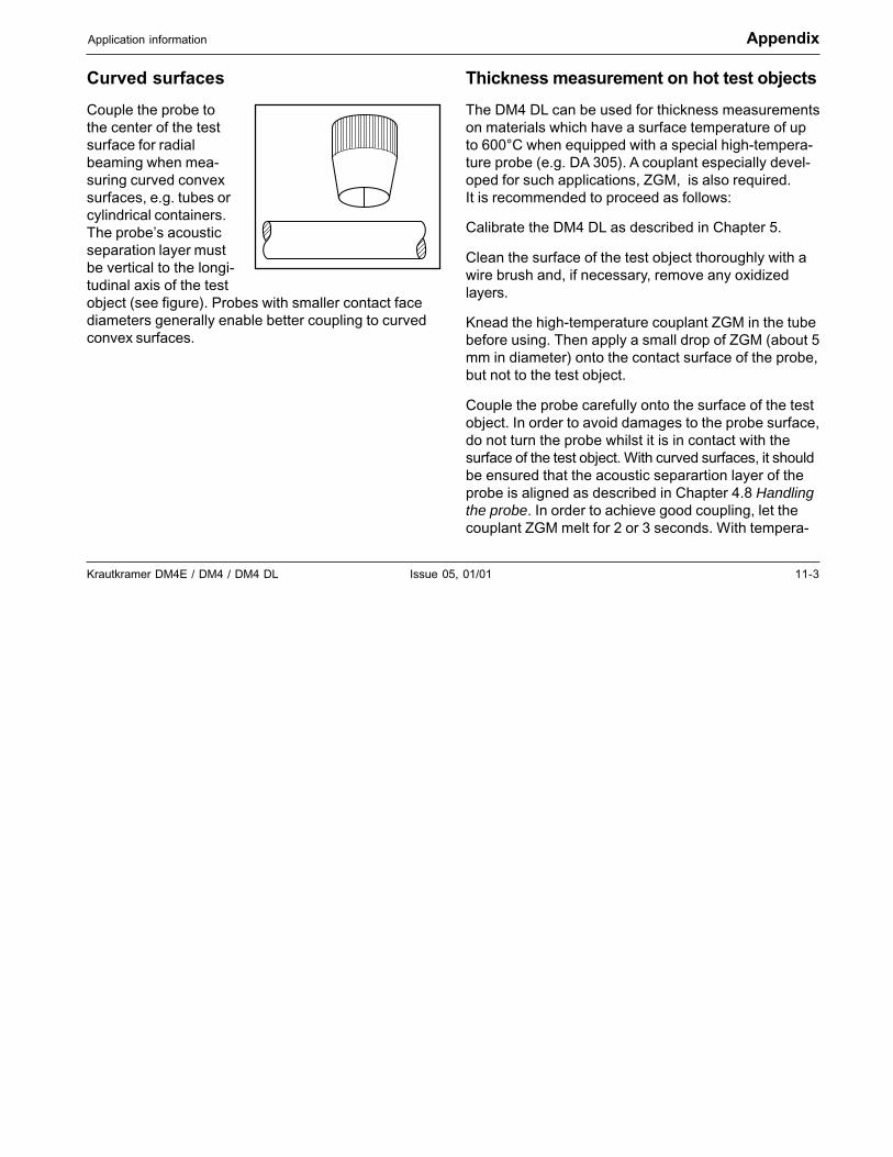
Krautkramer DM4E / DM4 / DM4 DL Issue 05, 01/01 11-3
Application information Appendix
Curved surfaces
Couple the probe tothe center of the testsurface for radialbeaming when mea-suring curved convexsurfaces, e.g. tubes orcylindrical containers.The probe’s acousticseparation layer mustbe vertical to the longi-tudinal axis of the testobject (see figure). Probes with smaller contact facediameters generally enable better coupling to curvedconvex surfaces.
Thickness measurement on hot test objects
The DM4 DL can be used for thickness measurementson materials which have a surface temperature of upto 600°C when equipped with a special high-tempera-ture probe (e.g. DA 305). A couplant especially devel-oped for such applications, ZGM, is also required.It is recommended to proceed as follows:
Calibrate the DM4 DL as described in Chapter 5.
Clean the surface of the test object thoroughly with awire brush and, if necessary, remove any oxidizedlayers.
Knead the high-temperature couplant ZGM in the tubebefore using. Then apply a small drop of ZGM (about 5mm in diameter) onto the contact surface of the probe,but not to the test object.
Couple the probe carefully onto the surface of the testobject. In order to avoid damages to the probe surface,do not turn the probe whilst it is in contact with thesurface of the test object. With curved surfaces, it shouldbe ensured that the acoustic separartion layer of theprobe is aligned as described in Chapter 4.8 Handlingthe probe. In order to achieve good coupling, let thecouplant ZGM melt for 2 or 3 seconds. With tempera-
11-4 Issue 05, 01/01 Krautkramer DM4E / DM4 / DM4 DL
Appendix Application information
tures above 550 °C, the couplant can suddenly ignite.However, this does not influence the coupling qualityin any way.
Do not couple the probe for more than 5 seconds. If athickness reading is not displayed within 5 seconds,remove the probe and cool it with water. Good cou-pling can be achieved on curved surfaces by slightlyrocking the probe.
Cool the probe after thickness measurement by im-mersing the contact face in water for a few seconds.Do not immerse it any longer than this!
Carefully remove any remaining couplant from theprobe before carrying out any further measurement.
In case of hot test objects and temperature variations,always use the DM4 in the DA3 mode (please seepage 4-6) as temperature variations are compensatedin this mode thanks to the continuous probe zero ad-justment even in the coupled state.
There are applications which go beyond the possibili-ties of the DM4 DL. If high-temperature measure-ments turn out to be unsatisfactory after several at-tempts using this method, it is recommended that ahigh-temperature probe be used in connection with auniversal ultrasonic instrument.

Krautkramer DM4E / DM4 / DM4 DL Issue 05, 01/01 11-5
Sound velocity table Appendix
11.2 Sound velocity table
Typical sound velocities in different materials(longitudinal waves)
Material m/s
Aluminium (alloyed) 6380
Aluminium (unalloyed) 6320
Aluminium oxide 9000 - 9850
Brass (CuZn30) 4700
Brass (CuZn40) 4400
Cast iron (globular) 5100 - 5700
Cast iron (laminated) 3800 - 4700
Cast iron (vermicular) 4700 - 5500
Copper 4700 - 5000
Epoxy resin 2600 - 2840
Glass (crown glass) 5800
Material m/s
Glass (safety glass) 6080
Glass (window glass) 5790
Gold 3240
Inconel 5700
Iron (unalloyed) 5960
Lead 2150
Magnesium 5800
Monel 5300 - 6000
Nickel (hard) 5810
Nickel (soft) 5610
Platinum 3960
Plexiglass (PMMA) 2730
Polyamide (6.6 Nylon) 2600
Polyethylene (PE hard) 2530
Polyethylene (PE soft) 2000
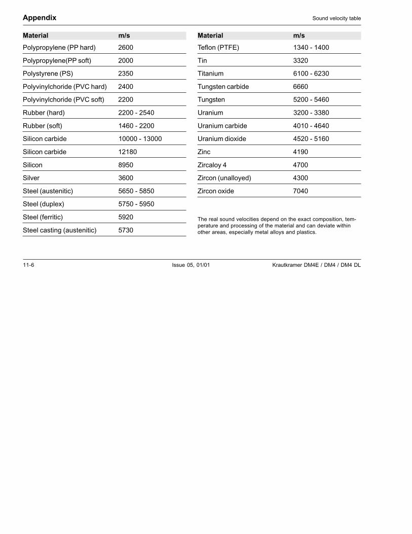
11-6 Issue 05, 01/01 Krautkramer DM4E / DM4 / DM4 DL
Appendix Sound velocity table
Material m/s
Polypropylene (PP hard) 2600
Polypropylene(PP soft) 2000
Polystyrene (PS) 2350
Polyvinylchoride (PVC hard) 2400
Polyvinylchoride (PVC soft) 2200
Rubber (hard) 2200 - 2540
Rubber (soft) 1460 - 2200
Silicon carbide 10000 - 13000
Silicon carbide 12180
Silicon 8950
Silver 3600
Steel (austenitic) 5650 - 5850
Steel (duplex) 5750 - 5950
Steel (ferritic) 5920
Steel casting (austenitic) 5730
Material m/s
Teflon (PTFE) 1340 - 1400
Tin 3320
Titanium 6100 - 6230
Tungsten carbide 6660
Tungsten 5200 - 5460
Uranium 3200 - 3380
Uranium carbide 4010 - 4640
Uranium dioxide 4520 - 5160
Zinc 4190
Zircaloy 4 4700
Zircon (unalloyed) 4300
Zircon oxide 7040
The real sound velocities depend on the exact composition, tem-perature and processing of the material and can deviate withinother areas, especially metal alloys and plastics.
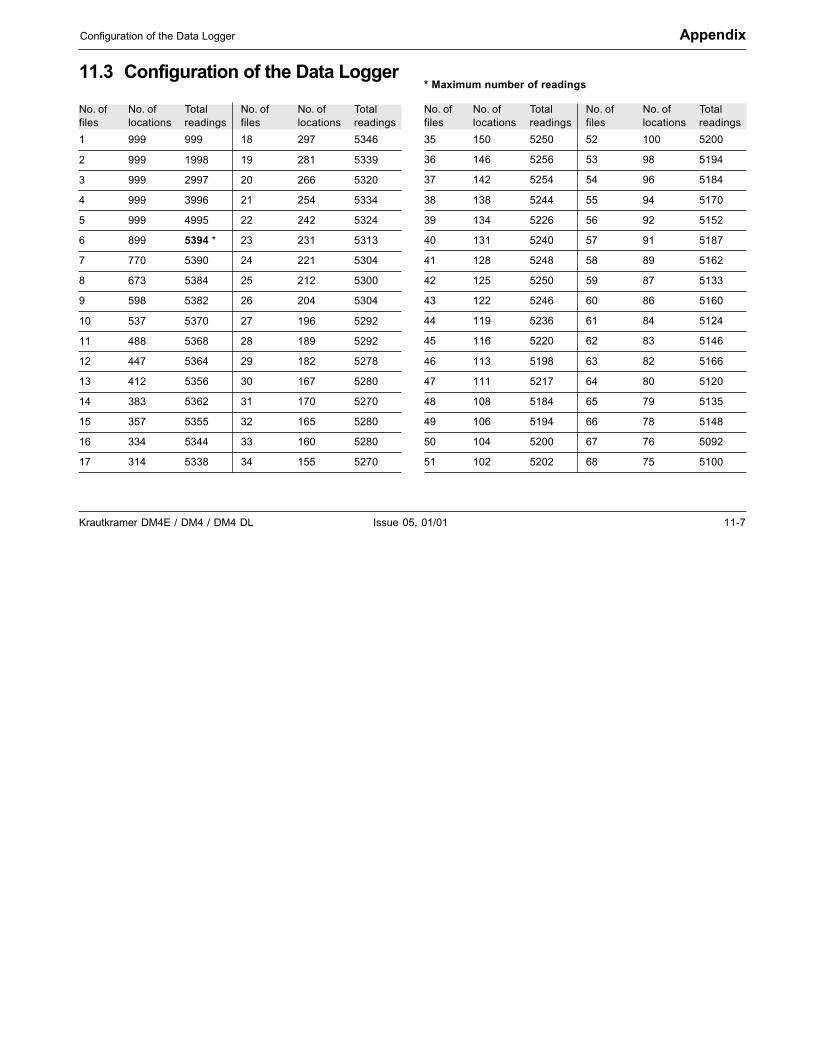
Krautkramer DM4E / DM4 / DM4 DL Issue 05, 01/01 11-7
Configuration of the Data Logger Appendix
11.3 Configuration of the Data Logger
No. of No. of Total No. of No. of Totalfiles locations readings files locations readings
1 999 999 18 297 5346
2 999 1998 19 281 5339
3 999 2997 20 266 5320
4 999 3996 21 254 5334
5 999 4995 22 242 5324
6 899 5394 * 23 231 5313
7 770 5390 24 221 5304
8 673 5384 25 212 5300
9 598 5382 26 204 5304
10 537 5370 27 196 5292
11 488 5368 28 189 5292
12 447 5364 29 182 5278
13 412 5356 30 167 5280
14 383 5362 31 170 5270
15 357 5355 32 165 5280
16 334 5344 33 160 5280
17 314 5338 34 155 5270
* Maximum number of readings
No. of No. of Total No. of No. of Totalfiles locations readings files locations readings
35 150 5250 52 100 5200
36 146 5256 53 98 5194
37 142 5254 54 96 5184
38 138 5244 55 94 5170
39 134 5226 56 92 5152
40 131 5240 57 91 5187
41 128 5248 58 89 5162
42 125 5250 59 87 5133
43 122 5246 60 86 5160
44 119 5236 61 84 5124
45 116 5220 62 83 5146
46 113 5198 63 82 5166
47 111 5217 64 80 5120
48 108 5184 65 79 5135
49 106 5194 66 78 5148
50 104 5200 67 76 5092
51 102 5202 68 75 5100
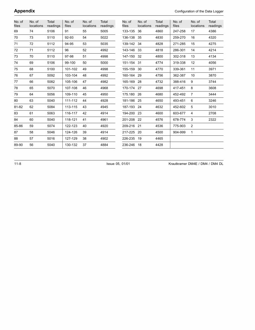
11-8 Issue 05, 01/01 Krautkramer DM4E / DM4 / DM4 DL
Appendix Configuration of the Data Logger
No. of No. of Total No. of No. of Totalfiles locations readings files locations readings
69 74 5106 91 55 5005
70 73 5110 92-93 54 5022
71 72 5112 94-95 53 5035
72 71 5112 96 52 4992
73 70 5110 97-98 51 4998
74 69 5106 99-100 50 5000
75 68 5100 101-102 49 4998
76 67 5092 103-104 48 4992
77 66 5082 105-106 47 4982
78 65 5070 107-108 46 4968
79 64 5056 109-110 45 4950
80 63 5040 111-112 44 4928
81-82 62 5084 113-115 43 4945
83 61 5063 116-117 42 4914
84 60 5040 118-121 41 4961
85-86 59 5074 122-123 40 4920
87 58 5046 124-126 39 4914
88 57 5016 127-129 38 4902
89-90 56 5040 130-132 37 4884
No. of No. of Total No. of No. of Totalfiles locations readings files locations readings
133-135 36 4860 247-258 17 4386
136-138 35 4830 259-270 16 4320
139-142 34 4828 271-285 15 4275
143-146 33 4818 286-301 14 4214
147-150 32 4800 302-318 13 4134
151-154 31 4774 319-338 12 4056
155-159 30 4770 339-361 11 3971
160-164 29 4756 362-387 10 3870
165-169 28 4732 388-416 9 3744
170-174 27 4698 417-451 8 3608
175.180 26 4680 452-492 7 3444
181-186 25 4650 493-451 6 3246
187-193 24 4632 452-602 5 3010
194-200 23 4600 603-677 4 2708
201-208 22 4576 678-774 3 2322
209-216 21 4536 775-903 2
217-225 20 4500 904-999 1
226-235 19 4465
236-246 18 4428

Krautkramer DM4E / DM4 / DM4 DL Issue 05, 01/01 11-9
EU declaration of conformity Appendix
11.4 EU declaration of conformity
The DM4 instruments meet the requirements of thefollowing EU directives:
❚ 89/336EEC -Electromagnetic compatibility-
The conformity of the above-mentioned product withthe regulations of the directive 89/336EEC is provenby the observance of the standard specifications
❚ EN 55011 12/1998 Class A, Group 2 and
❚ EN 50082-2 02/1996.

11-10 Issue 05, 01/01 Krautkramer DM4E / DM4 / DM4 DL
Appendix Service addresses
11.5 Service addresses
The DM4 instruments are manufactured according tostate-of-the-art methods using high-quality compo-nents. Thorough in-process inspections and a qualitymanagement system certified to DIN ISO 9001 ensurean optimum workmanship of the instrument.
Should you nevertheless detect an error or malfunc-tion on your product, please inform the KrautkrämerService responsible for your products by giving thedetails (if possible, error number) and a description ofthe error or malfunction.
If there’s anything specific you would like to knowabout the use, handling, operation and specificationsof your instrument, or about our Service Agreement,please contact your local Krautkrämer representative,or one of the following direct addresses:
Krautkrämer GmbH & Co. oHG
Service-CenterRobert-Bosch-Str. 3D – 50354 Hürth
or:
Postfach 1363D – 50330 Hürth
Tel.: +49 (0) 22 33 - 601 111Fax: +49 (0) 22 33 - 601 402E-Mail: [email protected]
France
Krautkramer FranceSAC Sans Souci68, chemin des OrmeauxF – 69760 Limonest
Tel.: +33 72 - 17 92 20Fax: +33 78 - 47 56 98
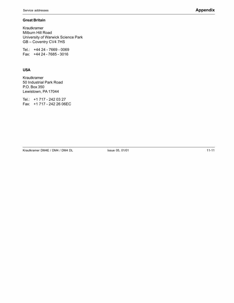
Krautkramer DM4E / DM4 / DM4 DL Issue 05, 01/01 11-11
Service addresses Appendix
Great Britain
KrautkramerMilburn Hill RoadUniversity of Warwick Science ParkGB – Coventry CV4 7HS
Tel.: +44 24 - 7669 - 0069Fax: +44 24 - 7685 - 3016
USA
Krautkramer50 Industrial Park RoadP.O. Box 350Lewistown, PA 17044
Tel.: +1 717 - 242 03 27Fax: +1 717 - 242 26 06EC

11-12 Issue 05, 01/01 Krautkramer DM4E / DM4 / DM4 DL

Krautkramer DM4E / DM4 / DM4 DL Issue 05, 01/01 12-1
Changes 12
12-2 Issue 05, 01/01 Krautkramer DM4E / DM4 / DM4 DL
Exisiting changes or additions are described in thischapter.
Otherwise this chapter remains empty.
Changes

Krautkramer DM4E / DM4 / DM4 DL Issue 05, 01/01 13-1
Index 13
13-2 Issue 05, 01/01 Krautkramer DM4E / DM4 / DM4 DL
Index
1-point calibration . . . . . . . . . . . . . . . . . . . . . . 5 -6
2-point calibration . . . . . . . . . . . . . . . . . . . . . . 5 -7
2-PT - 2-point calibration . . . . . . . . . . . . . . . . . 5 -7
A
Accelerated setting . . . . . . . . . . . . . . . . . . . . . 4 -9
Addresses . . . . . . . . . . . . . . . . . . . . . . . . . . 11 -10
Alarm limits . . . . . . . . . . . . . . . . . . . . . . . . . . 5 -14
Application notes . . . . . . . . . . . . . . . . . . . . . . 11 -2
Application software . . . . . . . . . . . . . . . . . . . . . 7 -8
AUTO mode . . . . . . . . . . . . . . . . . . . . . . . . . . . 4 -6
Automatic probe recognition . . . . . . . . . . . . . 4 -10
indication after switching on . . . . . . . . . . . . . 4 -6
Automatic probe zero adjustment . . . . . 4 -5, 4 -9
Automatic switch-off . . . . . . . . . . . . . . . . . . . . . 4 -7
B
Backlight . . . . . . . . . . . . . . . . . . . . . . . . . . . . . 5 -2
Bandpass filter . . . . . . . . . . . . . . . . . . . . . . . . 5 -16
Batteries
handling . . . . . . . . . . . . . . . . . . . . . . . . . . . . 8 -2
inserting . . . . . . . . . . . . . . . . . . . . . . . . . . . . 3 -2
supply . . . . . . . . . . . . . . . . . . . . . . . . . . . . . 3 -2
Battery symbol . . . . . . . . . . . . . . . . . . . . . . . . . 3 -2
Baud rate . . . . . . . . . . . . . . . . . . . . . . . . . . . . . 7 -3
C
Calibration . . . . . . . . . . . . . . . . . . . . . . . . . . . . 5 -4
Cleaning . . . . . . . . . . . . . . . . . . . . . . . . . . . . . 8 -2
Configuration
Data Logger . . . . . . . . . . . . . . . . . . . . . . . . 11 -7
Configuration Data Logger . . . . . . . . . . . . . . . . 6 -3
Couplant . . . . . . . . . . . . . . . . . . . . . . . . . . . . 1 -10
Krautkramer DM4E / DM4 / DM4 DL Issue 05, 01/01 13-3
Index
Couplant rests . . . . . . . . . . . . . . . . . . . . . . . . 1 -12
Coupling symbol . . . . . . . . . . . . . . . . 4 -10, 5 -10
D
DA3 mode . . . . . . . . . . . . . . . . . . . . . . . . . . . . 4 -6
Data Logger . . . . . . . . . . . . . . . . . . . . . . . . . . . 6 -2
clearing complete memory . . . . . . . . . . . . . 6 -12
configuration . . . . . . . . . . . . . . . . . . 6 -3, 11 -7
organization . . . . . . . . . . . . . . . . . . . . . . . . . 6 -3
Data transfer . . . . . . . . . . . . . . . . . . . . . . . . . . 7 -8
Data transfer format . . . . . . . . . . . . . . . . . . . . . 7 -2
Declaration of conformity . . . . . . . . . . . . . . . . 11 -9
Deleting values (Data Logger) . . . . . . . . . . . . 6 -11
DIALOG probes . . . . . . . . . . . . . . . . . . . . . . . 4 -10
Dialog probes . . . . . . . . . . . . . . . . . . . . 4 -5, 4 -9
DIF . . . . . . . . . . . . . . . . . . . . . . . . . . . . . . . . 5 -19
DIF - Difference mode . . . . . . . . . . . . . . . . . . 5 -15
Display
description . . . . . . . . . . . . . . . . . . . . . . . . . . 4 -2
Display indicationsafter switching on . . . . . . . . . . . . . . . . . . . . . 4 -5
DUAL MULTI mode . . . . . . . . . . . . . . . . . . . . 5 -17
E
EU declaration of conformity . . . . . . . . . . . . . 11 -9
F
File header . . . . . . . . . . . . . . . . . . . . . . . . . . . 7 -5
File selection . . . . . . . . . . . . . . . . . . . . . . . . . . 6 -5
Files (Data Logger)
deleting . . . . . . . . . . . . . . . . . . . . . . . . . . . 6 -11
Setting the number . . . . . . . . . . . . . . . . . . . . 6 -3
FLTR . . . . . . . . . . . . . . . . . . . . . . . . . . . . . . . 5 -19
FLTR - bandpass filter . . . . . . . . . . . . . . . . . . 5 -16
13-4 Issue 05, 01/01 Krautkramer DM4E / DM4 / DM4 DL
Index
G
GAIN . . . . . . . . . . . . . . . . . . . . . . . . . . . . . . . 5 -19
H
HEADprinting file header . . . . . . . . . . . . . . . . . . . . 7 -2
HI-L . . . . . . . . . . . . . . . . . . . . . . . . . . . . . . . . 5 -19
HI-L - High limit . . . . . . . . . . . . . . . . . . . . . . . 5 -14
Hot parts . . . . . . . . . . . . . . . . . . . . . . . . . . . . 11 -3
I
Instrument version . . . . . . . . . . . . . . . . . . . . . . 4 -5
Interface RS 232 . . . . . . . . . . . . . . . . . . . . . . 10 -2
ISPEC menu . . . . . . . . . . . . . . . . . . . . . . . . . . 7 -2
K
Keys . . . . . . . . . . . . . . . . . . . . . . . . . . . . . . . . 4 -4
L
LANG
selecting the language . . . . . . . . . . . . . . . . . 7 -2
Language of print report . . . . . . . . . . . . . . . . . 7 -3
LO-L . . . . . . . . . . . . . . . . . . . . . . . . . . . . . . . 5 -19
Low limit . . . . . . . . . . . . . . . . . . . . . . . . . . . 5 -14
Locations (Data Logger) . . . . . . . . . . . . . . . . . 6 -8
selection . . . . . . . . . . . . . . . . . . . . . . . . . . . . 6 -8
M
Maintenance . . . . . . . . . . . . . . . . . . . . . . . . . . 8 -3
Material surface . . . . . . . . . . . . . . . . . . . . . . . 5 -10
Measurement precision . . . . . . . . . . . . . . . . . 1 -12
Measurement through coating . . . . . . . . . . . . 5 -17
Measurement values (Data Logger)
deleting . . . . . . . . . . . . . . . . . . . . . . . . . . . 6 -11
storing . . . . . . . . . . . . . . . . . . . . . . . . . . . . . 6 -5
Krautkramer DM4E / DM4 / DM4 DL Issue 05, 01/01 13-5
Index
Measurment values (Data Logger)
viewing . . . . . . . . . . . . . . . . . . . . . . . . . . . . . 6 -9
MIN . . . . . . . . . . . . . . . . . . . . . . . . . . . . . . . . 5 -19
MIN mode
setting the time-out . . . . . . . . . . . . . . . . . . 5 -11
N
Non-dialog probes . . . . . . . . . . . . . . . . . 4 -6, 4 -9
O
OBST - obstruct location number . . . . . . . . . . 6 -8
Operation concept . . . . . . . . . . . . . . . . . . . . . . 4 -8
P
P0 - automatic probe zero . . . . . . . . . . . . . . . . 4 -9
P0 - automatic probe zero adjustement . . . . . . 5 -8
PC - data transfer . . . . . . . . . . . . . . . . . . . . . . 7 -8
Printer
preparing . . . . . . . . . . . . . . . . . . . . . . . . . . . 7 -2
Printer driver . . . . . . . . . . . . . . . . . . . . . . . . . . 7 -4
Printing data . . . . . . . . . . . . . . . . . . . . . . . . . . 7 -2
Printout . . . . . . . . . . . . . . . . . . . . . . . . . . . . . . 7 -6
Probe type numbers . . . . . . . . . . . . . . . . . . . 1 -12
Probe Zero Adjustment . . . . . . . . . . . . . . . . . . 4 -9
important notes . . . . . . . . . . . . . . . . . . . . . 1 -11
Probe zero adjustment . . . . . . . . . . . . . . . . . . . 4 -5
Probes
automatic recognition . . . . . . . . . . . . 1 -12, 4 -6
automatic recogniton . . . . . . . . . . . . . . . . . 4 -10
automatic zero adjustment . . . . . . . . . . . . . . 4 -9connection . . . . . . . . . . . . . . . . . . . . . . . . . . 3 -4
dialog probes . . . . . . . . . . . . . . . . . . . . . . . . 4 -5
handling . . . . . . . . . . . . . . . . . . . . . . . . . . . 4 -10
non-dialog probes . . . . . . . . . . . . . . . . . . . . 4 -6
specified for DM4 instruments . . . . . . . . . . . 2 -4
13-6 Issue 05, 01/01 Krautkramer DM4E / DM4 / DM4 DL
Index
R
REP
selecting the printer driver . . . . . . . . . . . . . . 7 -2
Report printout . . . . . . . . . . . . . . . . . . . . . . . . . 7 -6
Resolution units . . . . . . . . . . . . . . . . . . . . . . . . 5 -2
RS 232 interface . . . . . . . . . . . . . . . . . . . . . . 10 -2
pin layout . . . . . . . . . . . . . . . . . . . . . . . . . . 10 -3
S
Sensitivitysetting the GAIN function . . . . . . . . . . . . . . 5 -13
Service addresses . . . . . . . . . . . . . . . . . . . . 11 -10
Software version . . . . . . . . . . . . . . . . . . . . . . . 4 -5
Sound velocity
setting the unit . . . . . . . . . . . . . . . . . . . . . . . 5 -3
Sound velocity table . . . . . . . . . . . . . . . . . . . . 11 -5
SPEC . . . . . . . . . . . . . . . . . . . . . . . . . . . . . . 5 -19
SPEC menu . . . . . . . . . . . . . . . . . . . . . 4 -8, 5 -13
Star display . . . . . . . . . . . . . . . . . . . . . . . . . . 4 -10
STAT
printing statistical data . . . . . . . . . . . . . . . . . 7 -2
Statistics . . . . . . . . . . . . . . . . . . . . . . . . . . . . . 7 -5
Storage capacity
Data Logger . . . . . . . . . . . . . . . . . . . . . . . . . 6 -3
Storing data (Data Logger) . . . . . . . . . . . . . . . 6 -5
Surface conditions . . . . . . . . . . . . . . . . . . . . . 11 -2
Switch-off
automatic . . . . . . . . . . . . . . . . . . . . . . . . . . . 4 -7
Switching on and off . . . . . . . . . . . . . . . . . . . . 4 -5
T
Temperature conditions . . . . . . . . . . . 1 -11, 5 -10
probes . . . . . . . . . . . . . . . . . . . . . . . . . . . . . 4 -6
Krautkramer DM4E / DM4 / DM4 DL Issue 05, 01/01 13-7
Index
Thickness testing
conditions . . . . . . . . . . . . . . . . . . . . . . . . . . . 1 -7
limits. . . . . . . . . . . . . . . . . . . . . . . . . . . . . . . 1 -8
THK - thickness measurement mode. . . . . . . 5 -10
Through-coating measurement . . . . . . . . . . . 5 -17
Time-out . . . . . . . . . . . . . . . . . . . . . . . . . . . . 5 -11
V
VEL . . . . . . . . . . . . . . . . . . . . . . . . . . . 5 -5, 5 -19
setting the sound velocity unit . . . . . . . . . . . 5 -3
Voltage supply . . . . . . . . . . . . . . . . . . . . . . . . . 3 -2
Z
Zero
Automatic probe zero adjustment . . . . 4 -5, 4 -9

13-8 Issue 05, 01/01 Krautkramer DM4E / DM4 / DM4 DL
GE Inspection Technologies is an active participant in Europe’s Waste Electrical and ElectronicEquipment (WEEE) take-back initiative, directive 2002/96/EC.
The equipment you purchased required the extraction and use of natural resources for its production. It may contain hazardous substances that could impact health and theenvironment. In order to avoid the dissemination of those substances in our environment and to diminish the pressure on the natural resources, we encourage you to use the appropriatetake-back systems. If you need more information on the collection, reuse and recycling systems, please contact your local or regional waste administration.
Visit http://www.geinspectiontechnologies.com/en/aboutus/ehs/index.html for take-backinstructions and more information about this initiative.
The equipment that you bought has required the extraction and use of natural resources for its production. It may contain hazardous substances that could impact health and the environment.
In order to avoid the dissemination of those substances in our environment and to diminish the pressure on the natural resources, we encourage you to use the appropriate take-back systems. Those systems will reuse or recycle most of the materials of your end life equipment in a sound way.
The crossed-out wheeled bin symbol invites you to use those systems.
If you need more information on the collection, reuse and recycling systems, please contact your local or regional waste administration.
Visit www.ge.com/inspectiontechnologies for take-back instructions and more information about this initiative.
Environmental Compliance
084-028-593 Rev. 6
©2007 General Electric Company.We reserve the right to technical modifications without prior notice.
www.ge.com/inspectiontechnologies
Printed in USA
Customer Support Centers
North/South America50 Industrial Park RoadLewistown, PA 17044Tel: 866 243 2638 717 242 0327
GermanyRobert Bosch Str.50354 HürthTel: +49 2233 601 0
United Kingdom/Ireland892 Charter Avenue CanleyCoventry CV4 8AFTel: +44 845 130 3925
France68, Chemin des OrmeauxLimonest 69760Tel: +33 47 217 9216
SpainSan Maximo, 31, Planta 4A, Nave 6Madrid 28041Tel: +34 195 005 990
China5F, Hongcao Building421 Hongcao RoadShanghai 200233Tel: +86 800 820 1876 +86 21 3414 4620
Japan7F Medie Corp Bldg. 82-4-14 Kichijoji Honcho,Musashino-shiTokyo 180-0004Tel: +81 442 67 7067