kichler xenon under-cabinet 4u120x · before installing: 1. all installations should comply with...
TRANSCRIPT

BEFORE INSTALLING:1. All installations should comply with National and local electrical codes. If you have any doubts concerning installation contact a qualified, licensed electrician.2. This fixture can only be used with Kichler Cabinet Lighting fixtures and accessories.3. This fixture must be installed using interconnect cables 10571 (9”), 10572 (14”), 10573 (21”), connected to wire module 10570 or existing Kichler Cabinet Lighting fixture and can also be installed by directly connecting to another Kichler Cabinet Lighting fixture.4. Mounting surface should be a minimum of ½” thick.5. When using interconnect cables or connecting fixture to fixture, fixtures can have a maximum of 3 units in a single run.
INSTALLATION INSTRUCTIONS USING LINE CONNECTION
1. Turn off power.2. Open wiring compartment by inserting flathead screwdriver into the slots and wedging cover open. (ref. FIG. 1)3. Remove knock-out that allows for easiest access to conduit. Knock-out should be removed by inserting flat-headed screwdriver into the knock-out slot and rocking up and down until knock-out releases. (ref. FIG. 2)4. Install conduit connector in knock-out hole on fixture housing.5. Run wire through installed conduit connector ensuring that at least 3” of wire extend into the wiring compartment. The provided conduit connector may only be used with the following: • 14/2 to 10/2 steel armored cable; • 3/8” trade sized reduced wall flexible steel or aluminum conduit; or • 14/2 to 10/2 non-metallic sheathed cable 6. Tighten screws on conduit connector to clamp wire into place.7. Hold the fixture in the desired mounting location and drive mounting screws into cabinet surface until fixture is secure. If screws are difficult to install, mark holes and drill 1/16” maximum pilot holes. (ref. FIG. 3)8. Make grounding connection using supplied wire nut found in parts bag.9. Make wire connections (connectors provided).
10. Open glass diffuser by pressing on tab of each diffuser end cap. Lift and slide diffuser towards rear of fixture. Remove protective sleeve(s) from bulb(s).11. Close glass diffuser by swinging edge with tabs up towards fixtures until pegs by tabs slip into slots at the front of the fixture end caps. Slide tabs forward, allowing pegs to seat in slots. Lens should be level and flush with fixture.12. Swing the cover towards the fixture and close it by pressing at the ends of the cover until the cover snaps into place and is flush with the fixture. CAUTION: Ensure that the wires are not pinched or damaged by any part of the metal housing or clips. NOTE: See Step 2 to re-access wiring compartment.13. Place connector cover over any connector not being used. (ref. FIG. 414. Turn on power.
Model Number
Voltage Wattage
4U120X08_ _ _
4U120X12_ _ _
4U120X22_ _ _
4U120X30_ _ _
120V
120V
120V
120V
20W
40W
60W
80W
FIG. 4
Date Issued: 12/4/15 IS-4U120X-US_English
Connect Black or Red Supply Wire to:
Connect White Supply Wire to:
Black White
*Parallel cord (round & smooth) *Parallel cord (square & ridged)
Clear, Brown, Gold or Black without tracer
Clear, Brown, Gold or Black with tracer
Insulated wire (other than green) with copper conductor
Insulated wire (other than green) with silver conductor
*Note: When parallel wires (SPT I & SPT II) are used. The neutral wire is square shaped or ridged and the other wire will be round inshape or smooth (see illus.) Neutral Wire
See Page 2 for:
• Installation Instructions using Plug-In Cord
• Installation Instructions using Interconnect Cable
• Installation Instructions for Fixture to Fixture
• Installation Instructions for Replacing Lamps
Page 1
We’re here to help 866-558-5706Hrs: M-F 9am to 5pm EST
FIG. 1
Kichler® Xenon Under-Cabinet4U SERIES, CP301173
4U120X_ _ _ _ _
NOTE: Read all instructions thoroughly before starting installation.
CAUTION: To reduce the risk of fire, electric shock, or injury to persons: a) Use only insulated staples or plastic ties to secure cords; b) Route and secure cords so that they will not be pinched or damaged when the fixture is pushed to the wall; c) Not intended for recessed installation in ceiling, or soffits; d) Not intended for surface installation inside built-in furnishings such as kitchen cabinets, china cabinets, or trophy cases; e) The National Electric Code (NEC) does not permit cords to be concealed where damage to insulation may go unnoticed. To prevent fire danger, do not run cord behind walls, ceilings, soffits, or cabinets where it may be inaccessible for examination. Cords should be visually examined periodically and immediately replaced when any damage is noted.
FIG. 3
CONDUIT CONNECTOR
KNOCK-OUT
MOUNTING SCREWMOUNTING SCREW
22" & 30" MODELS ONLY
KNOCK-OUT
FIG. 2

FIG. 7
FIG. 5
INSTALLATION INSTRUCTIONS USING PLUG-IN CORD
1. Hold the fixture in the desired mounting location, leaving approximately 2 ½” clearance for plug-in cord, and not more than 5’ from the nearest outlet. Drive mounting screws into cabinet surface until fixture is secure. If screws are difficult to install, mark holes and drill 1/16” maximum pilot holes. (ref. FIG. 5) NOTE: For 22” and 30” fixtures, open wire compartment by inserting flathead screwdriver into the slots and wedging cover open to install center screw. Once installed, swing the cover towards the fixture and close it by pressing at the ends of the cover until the cover snaps into place and is flush with the fixture.2. Connect cord into fixture female connector. CAUTION: Never connect the plug-in cord to a fixture or system that is already energized3. Peel backing off retaining clip(s) and affix to desired location(s). Surface should be as clean as possible.4. Slip cables into clip(s) and snap closed. 5. Open glass diffuser by pressing on tab of each diffuser end cap. Lift and slide diffuser towards rear of fixture. Remove protective sleeve(s) from bulb(s).
INSTALLATION INSTRUCTIONS USING INTERCONNECT CABLE
1. Turn off power.2. Hold the fixture in the desired mounting location, not more than 21” from nearest interconnected fixture, allowing approximately 2 ½” clearance for interconnect cables. Drive mounting screws into cabinet surface until fixture is secure. If screws are difficult to install, mark holes and drill 1/16” maximum pilot holes. (ref. FIG. 6) NOTE: For 22” and 30” fixtures, open wire compartment by inserting flathead screwdriver into the slots and wedging cover open to install center screw. Once installed, swing the cover towards the fixture and close it by pressing at the ends of the cover until the cover snaps into place and is flush with the fixture.3. Connect fixture to existing Kichler Cabinet Lighting system using interconnect cable.4. Hold interconnect cable to mounting surface and determine best path for cable. If interconnect cable is being run from cabinet to cabinet a notch such as a “V” could be cut in cabinet side panels to help keep cables out of site. NOTE: Interconnect cable is not intended for use through or concealed behind walls, floors or ceilings.5. Peel backing off retaining clip(s) and affix to desired location(s). Surface should be as clean as possible.6. Slip cables into clip(s) and snap closed.
INSTALLING FIXTURE TO FIXTURE
1. Turn off power.2. Align connector on end of new fixture with connector on end of existing fixture. (ref. FIG. 7)3. Push new fixture to existing fixture until fixtures are flush and connectors snap together.4. Drive mounting screws into cabinet surface until fixture is secure. If screws are difficult to install, mark holes, remove fixture and drill 1/16” maximum pilot holes. NOTE: For 22” and 30” fixtures, open wire compartment by inserting flathead screwdriver into the slots and wedging cover open to install center screw. Once installed, swing the cover towards the fixture and close it by pressing at the ends of the cover until the cover snaps into place and is flush with the fixture.5. Open glass diffuser by pressing on tab of each diffuser end cap. Lift and slide diffuser towards rear of fixture. Remove protective sleeve(s) from bulb(s).6. Close glass diffuser by swinging edge with tabs up towards fixtures until pegs by tabs slip into slots at the front of the fixture end caps. Slide tabs forward, allowing pegs to seat in slots. Lens should be level and flush with fixture.7. If this will be an end fixture in a run, use connector cover over any connector not being used.8. Turn on power.
FIG. 6
Date Issued: 12/4/15 IS-4U120X-US_English
Page 2
See Page 1 for:
• Installation Instructions using Line Connection
INSTALLING REPLACEMENT LAMPS
1. Turn off fixture and allow to completely cool before replacing lamp.2. Open glass diffuser by pressing on tab of each diffuser end cap. Lift and slide diffuser towards rear of fixture.3. Remove lamp by pulling straight out from the lamp socket.4. Reference lamp mounting bracket for replacement lamp information. Use only maximum 120V, 20W Xenon lamp.5. Close glass diffuser by swinging edge with tabs up towards fixtures until pegs by tabs slip into slots at the front of the fixture end caps. Slide tabs forward, allowing pegs to seat in slots. Lens should be level and flush with fixture.
7. Open glass diffuser by pressing on tab of each diffuser end cap. Lift and slide diffuser towards rear of fixture. Remove protective sleeve(s) from bulb(s).8. Close glass diffuser by swinging edge with tabs up towards fixtures until pegs by tabs slip into slots at the front of the fixture end caps. Slide tabs forward, allowing pegs to seat in slots. Lens should be level and flush with fixture.9. If this will be an end fixture in a run, use connector cover over any connector not being used.10. Turn on power.
6. Close glass diffuser by swinging edge with tabs up towards fixtures until pegs by tabs slip into slots at the front of the fixture end caps. Slide tabs forward, allowing pegs to seat in slots. Lens should be level and flush with fixture.7. If this will be an end fixture in a run, use connector cover over any connector not being used.8. Plug cord into outlet.
We’re here to help 866-558-5706Hrs: M-F 9am to 5pm EST

BEFORE INSTALLING:1. All installations should comply with National and local electrical codes. If you have any doubts concerning installation contact a qualified, licensed electrician.2. This fixture can only be used with Kichler Cabinet Lighting fixtures and accessories.3. This fixture must be installed using interconnect cables 10571 (9”), 10572 (14”), 10573 (21”), connected to wire module 10570 or existing Kichler Cabinet Lighting fixture and can also be installed by directly connecting to another Kichler Cabinet Lighting fixture.4. Mounting surface should be a minimum of ½” thick.5. When using interconnect cables or connecting fixture to fixture, fixtures can have a maximum of 3 units in a single run.
INSTALLATION INSTRUCTIONS USING LINE CONNECTION
1. Turn off power.2. Open wiring compartment by inserting flathead screwdriver into the slots and wedging cover open. (ref. FIG. 1)3. Remove knock-out that allows for easiest access to conduit. Knock-out should be removed by inserting flat-headed screwdriver into the knock-out slot and rocking up and down until knock-out releases. (ref. FIG. 2)4. Install conduit connector in knock-out hole on fixture housing.5. Run wire through installed conduit connector ensuring that at least 3” of wire extend into the wiring compartment. The provided conduit connector may only be used with the following: • 14/2 to 10/2 steel armored cable; • 3/8” trade sized reduced wall flexible steel or aluminum conduit; or • 14/2 to 10/2 non-metallic sheathed cable 6. Tighten screws on conduit connector to clamp wire into place.7. Hold the fixture in the desired mounting location and drive mounting screws into cabinet surface until fixture is secure. If screws are difficult to install, mark holes and drill 1/16” maximum pilot holes. (ref. FIG. 3)8. Make grounding connection using supplied wire nut found in parts bag.9. Make wire connections (connectors provided).
10. Open glass diffuser by pressing on tab of each diffuser end cap. Lift and slide diffuser towards rear of fixture. Remove protective sleeve(s) from bulb(s).11. Close glass diffuser by swinging edge with tabs up towards fixtures until pegs by tabs slip into slots at the front of the fixture end caps. Slide tabs forward, allowing pegs to seat in slots. Lens should be level and flush with fixture.12. Swing the cover towards the fixture and close it by pressing at the ends of the cover until the cover snaps into place and is flush with the fixture. CAUTION: Ensure that the wires are not pinched or damaged by any part of the metal housing or clips. NOTE: See Step 2 to re-access wiring compartment.13. Place connector cover over any connector not being used. (ref. FIG. 4)14. Turn on power.
Model Number
Voltage Wattage
4U120X08_ _ _
4U120X12_ _ _
4U120X22_ _ _
4U120X30_ _ _
120V
120V
120V
120V
20W
40W
60W
80W
FIG. 4
Date Issued: 12/4/15 IS-4U120X-CB_English
Connect Black or Red Supply Wire to:
Connect White Supply Wire to:
Black White
*Parallel cord (round & smooth) *Parallel cord (square & ridged)
Clear, Brown, Gold or Black without tracer
Clear, Brown, Gold or Black with tracer
Insulated wire (other than green) with copper conductor
Insulated wire (other than green) with silver conductor
*Note: When parallel wires (SPT I & SPT II) are used. The neutral wire is square shaped or ridged and the other wire will be round inshape or smooth (see illus.) Neutral Wire
See Page 2 for:
• Installation Instructions using Plug-In Cord
• Installation Instructions using Interconnect Cable
• Installation Instructions for Fixture to Fixture
• Installation Instructions for Replacing Lamps
Page 1
We’re here to help 866-558-5706Hrs: M-F 9am to 5pm EST
FIG. 1
Kichler® Xenon Under-Cabinet4U SERIES, CP301173
4U120X_ _ _ _ _
NOTE: Read all instructions thoroughly before starting installation.
CAUTION: To reduce the risk of fire, electric shock, or injury to persons: a) Use only insulated staples or plastic ties to secure cords; b) Route and secure cords so that they will not be pinched or damaged when the fixture is pushed to the wall; c) Not intended for recessed installation in ceiling, or soffits; d) Not intended for surface installation inside built-in furnishings such as kitchen cabinets, china cabinets, or trophy cases; e) The National Electric Code (NEC) does not permit cords to be concealed where damage to insulation may go unnoticed. To prevent fire danger, do not run cord behind walls, ceilings, soffits, or cabinets where it may be inaccessible for examination. Cords should be visually examined periodically and immediately replaced when any damage is noted.
FIG. 3
CONDUIT CONNECTOR
KNOCK-OUT
MOUNTING SCREWMOUNTING SCREW
22" & 30" MODELS ONLY
INSTRUCTIONSFor Assembling and Installing Fixtures in Canada
Pour L’assemblage et L’installation Au Canada
KNOCK-OUT
FIG. 2
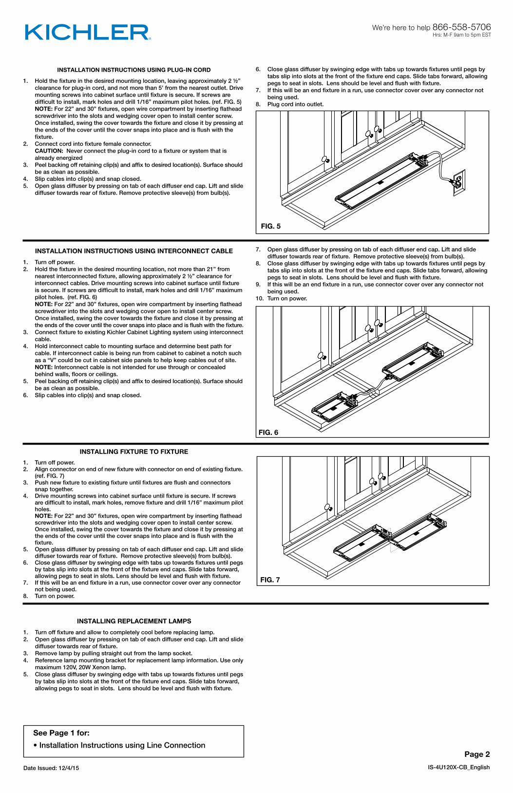
FIG. 6
FIG. 7
FIG. 5
INSTALLATION INSTRUCTIONS USING PLUG-IN CORD
1. Hold the fixture in the desired mounting location, leaving approximately 2 ½” clearance for plug-in cord, and not more than 5’ from the nearest outlet. Drive mounting screws into cabinet surface until fixture is secure. If screws are difficult to install, mark holes and drill 1/16” maximum pilot holes. (ref. FIG. 5) NOTE: For 22” and 30” fixtures, open wire compartment by inserting flathead screwdriver into the slots and wedging cover open to install center screw. Once installed, swing the cover towards the fixture and close it by pressing at the ends of the cover until the cover snaps into place and is flush with the fixture.2. Connect cord into fixture female connector. CAUTION: Never connect the plug-in cord to a fixture or system that is already energized3. Peel backing off retaining clip(s) and affix to desired location(s). Surface should be as clean as possible.4. Slip cables into clip(s) and snap closed. 5. Open glass diffuser by pressing on tab of each diffuser end cap. Lift and slide diffuser towards rear of fixture. Remove protective sleeve(s) from bulb(s).
INSTALLATION INSTRUCTIONS USING INTERCONNECT CABLE
1. Turn off power.2. Hold the fixture in the desired mounting location, not more than 21” from nearest interconnected fixture, allowing approximately 2 ½” clearance for interconnect cables. Drive mounting screws into cabinet surface until fixture is secure. If screws are difficult to install, mark holes and drill 1/16” maximum pilot holes. (ref. FIG. 6) NOTE: For 22” and 30” fixtures, open wire compartment by inserting flathead screwdriver into the slots and wedging cover open to install center screw. Once installed, swing the cover towards the fixture and close it by pressing at the ends of the cover until the cover snaps into place and is flush with the fixture.3. Connect fixture to existing Kichler Cabinet Lighting system using interconnect cable.4. Hold interconnect cable to mounting surface and determine best path for cable. If interconnect cable is being run from cabinet to cabinet a notch such as a “V” could be cut in cabinet side panels to help keep cables out of site. NOTE: Interconnect cable is not intended for use through or concealed behind walls, floors or ceilings.5. Peel backing off retaining clip(s) and affix to desired location(s). Surface should be as clean as possible.6. Slip cables into clip(s) and snap closed.
INSTALLING FIXTURE TO FIXTURE
1. Turn off power.2. Align connector on end of new fixture with connector on end of existing fixture. (ref. FIG. 7)3. Push new fixture to existing fixture until fixtures are flush and connectors snap together.4. Drive mounting screws into cabinet surface until fixture is secure. If screws are difficult to install, mark holes, remove fixture and drill 1/16” maximum pilot holes. NOTE: For 22” and 30” fixtures, open wire compartment by inserting flathead screwdriver into the slots and wedging cover open to install center screw. Once installed, swing the cover towards the fixture and close it by pressing at the ends of the cover until the cover snaps into place and is flush with the fixture.5. Open glass diffuser by pressing on tab of each diffuser end cap. Lift and slide diffuser towards rear of fixture. Remove protective sleeve(s) from bulb(s).6. Close glass diffuser by swinging edge with tabs up towards fixtures until pegs by tabs slip into slots at the front of the fixture end caps. Slide tabs forward, allowing pegs to seat in slots. Lens should be level and flush with fixture.7. If this will be an end fixture in a run, use connector cover over any connector not being used.8. Turn on power.
Date Issued: 12/4/15 IS-4U120X-CB_English
Page 2
See Page 1 for:
• Installation Instructions using Line Connection
INSTALLING REPLACEMENT LAMPS
1. Turn off fixture and allow to completely cool before replacing lamp.2. Open glass diffuser by pressing on tab of each diffuser end cap. Lift and slide diffuser towards rear of fixture.3. Remove lamp by pulling straight out from the lamp socket.4. Reference lamp mounting bracket for replacement lamp information. Use only maximum 120V, 20W Xenon lamp.5. Close glass diffuser by swinging edge with tabs up towards fixtures until pegs by tabs slip into slots at the front of the fixture end caps. Slide tabs forward, allowing pegs to seat in slots. Lens should be level and flush with fixture.
7. Open glass diffuser by pressing on tab of each diffuser end cap. Lift and slide diffuser towards rear of fixture. Remove protective sleeve(s) from bulb(s).8. Close glass diffuser by swinging edge with tabs up towards fixtures until pegs by tabs slip into slots at the front of the fixture end caps. Slide tabs forward, allowing pegs to seat in slots. Lens should be level and flush with fixture.9. If this will be an end fixture in a run, use connector cover over any connector not being used.10. Turn on power.
6. Close glass diffuser by swinging edge with tabs up towards fixtures until pegs by tabs slip into slots at the front of the fixture end caps. Slide tabs forward, allowing pegs to seat in slots. Lens should be level and flush with fixture.7. If this will be an end fixture in a run, use connector cover over any connector not being used.8. Plug cord into outlet.
We’re here to help 866-558-5706Hrs: M-F 9am to 5pm EST

Date Issued: 12/4/15 IS-4U120X-CB_Canadian French
Voir les pages 2 pour:
• Instructions d’installation à l’aide d’un cordon enfichable
• Instructions d’installation à l’aide d’un câble d’interconnexion
• Instructions d’installation pour un luminaire sur un luminaire
• Instructions d’installation pour le remplacement des ampoules
Page 1
We’re here to help 866-558-5706Hrs: M-F 9am to 5pm EST
Kichler® Xenon pour dessous d’armoireSÉRIE 4U, CP301173
4U120X_ _ _ _ _
AVANT DE PROCÉDER À L’INSTALLATION:1. Toutes les installations doivent être conformes aux codes électriques nationaux et locaux. En cas de doute concernant l’installation, contacter un électricien qualifié.2. Ce luminaire peut être utilisé uniquement avec les luminaires et les acces soires pour l’éclairage pour armoire Kichler.3. Ce luminaire doit être installé à l’aide de câbles d’interconnexion 10571 (9 po), 10572 (14 po), 10573 (21 po), connectés au module des câblages 10570 ou au luminaire d’éclairage pour armoire Kichler existant et peut également être installé en le connectant directement à un autre luminaire d’éclairage pour armoire Kichler.4. L’épaisseur de la surface de montage doit être de 1,7 cm minimum.5. Lors de l’utilisation des câbles d’interconnexion ou de raccordement entre luminaires, les luminaires peuvent avoir un maximum de 3 unités dans une interconnexion.
INSTRUCTIONS D’INSTALLATION AVEC LE RACCORDEMENT AU SECTEUR
1. Couper le courant.2. Ouvrir le compartiment de câblage en insérant un tournevis à tête plate dans les fentes et en dégageant le couvercle (voir FIG. 1).3. Retirer la partie défonçable pour faciliter l’accès au conduit. La partie défonçable doit être retirée en insérant un tournevis à tête plate dans la fente de la partie défonçable et basculant de haut en bas jusqu’à ce que la partie défonçable soit éjectée (voir FIG. 2)4. Installer le connecteur de conduit dans le trou de la partie défonçable sur le boîtier du luminaire.5. Acheminer le fil par le connecteur du conduit installé en veillant à ce qu’au moins 3 po de fil se trouvent dans le compartiment de câblage. Le connecteur de conduit fourni peut être utilisé uniquement avec les éléments suivants: • Câble blindé en acier de 14/2 à 10/2; • Conduit commercial en aluminium ou en acier flexible pour mur à calibre réduit de 3/8 po; ou • Câble sous gaine non métallique de 14/2 à 10/2. 6. Serrer les vis sur le raccord de conduit pour fixer le fil.7. Placer le luminaire à l’endroit souhaité pour l’installation et serrer les vis de montage dans la surface de l’armoire jusqu’à ce que le luminaire soit bloqué. Si les vis sont difficiles à installer, marquer des repères pour les trous et percer des trous pilotes de 1/16 po maximum (voir FIG. 3).8. Faire le raccordement de mise à la terre en utilisant écrou de fil fourni dans le sac de pièces.9. Raccorder les fils (connecteurs fournis).
10. Ouvrir le diffuseur en verre en appuyant sur la languette de chaque embout diffuseur. Soulever et glisser le diffuseur vers l’arrière du luminaire. Retirer le(s) manchon(s) protecteur(s) des ampoules.11. Fermer le diffuseur en verre en déplaçant le bord avec des languettes vers les luminaires jusqu’à ce que les chevilles près des onglets glissent dans les fentes à l’avant des embouts de luminaire. Déplacer les languettes en les glissant vers l’avant, pour permettre aux chevilles de se loger dans les fentes. La lentille doit être de niveau et aligner au luminaire.
Numéro de modèle
Voltage Wattage
4U120X08_ _ _
4U120X12_ _ _
4U120X22_ _ _
4U120X30_ _ _
120V
120V
120V
120V
20W
40W
60W
80W
FIG. 4
Connecter le fil noir ourouge de la boite
Connecter le fil blanc de la boîte
A Noir A Blanc
*Au cordon parallèle (rond et lisse) *Au cordon parallele (à angles droits el strié)
Au bransparent, doré, marron, ou noir sans fil distinctif
Au transparent, doré, marron, ounoir avec un til distinctif
Fil isolé (sauf fil vert) avec conducteur en cuivre
Fil isolé (sauf fil vert) avec conducteur en argent
*Remarque: Avec emploi d’un fil paralléle (SPT I et SPT II). Le fil neutre est á anglesdroits ou strié et l’autre fil doit étre rond oulisse (Voir le schéma). Fil Neutre
REMARQUE: Prière de lire attentivement toutes les instructions avant de procéder à l’installation.
ATTENTION: Pour réduire le risque d’incendie, de choc électrique ou de blessure: a) Utiliser uniquement des agrafes isolés ou des attaches en plastique pour sécuriser les cordons; b) Acheminer et sécuriser les cordons de manière à ce qu’ils ne soient pas pincé ni endommagé lorsque le luminaire est poussé contre le mur; c) Non destiné à une installation encastrée dans le plafond, ou dans les sous-faces; d) Non destiné à l’installation sur la surface à l’intérieur de ameublements intégrés, tels que les armoires de cuisine, des vaisseliers, ou des présentoirs à trophées; e) Le Code national de l’électricité (NEC) ne permet pas que les cordons soient dissimulés sous risque que les dommages à l’isolation passent inaperçus. Pour éviter le danger d’incendie, ne pas acheminer le cordon derrière les murs, les plafonds, les sous-faces, ou des armoires où il pourrait ne pas être accessible pour inspection. Les cordons doivent être examinés visuellement régulièrement et remplacés immédiatement si des dommages sont constatés.
FIG. 3
CONNECTEUR DU CONDUIT
PARTIEDÉFONÇABLE
VIS DE MONTAGEVIS DE MONTAGE
MODÈLES DE 22 po et 30 po UNIQUEMENT
INSTRUCTIONSFor Assembling and Installing Fixtures in Canada
Pour L’assemblage et L’installation Au Canada
12. Faire pivoter le couvercle vers le luminaire et le fermer en appuyant sur les extrémités du couvercle jusqu’à ce qu’il s’enclenche en place et soit aligné avec le luminaire. ATTENTION: S’assurer que les fils ne sont pas pincés ni endommagés par des pièces du boîtier métallique ou les attaches. REMARQUE: Voir l’étape 2 pour accéder au nouveau compartiment de câblage.13. Placer le couvercle des connecteurs sur les connecteurs qui ne sont pas utilisés (voir FIG. 4).14. Remettre le courant.
FIG. 1
PARTIE DÉFONÇABLE
FIG. 2

FIG. 7
FIG. 5
INSTRUCTIONS D’INSTALLATION À L’AIDE D’UN CORDON ENFICHABLE
1. Maintenir le luminaire à l’emplacement de montage souhaité, laissant un jeu d’environ 2 ½ po pour le cordon enfichable, et pas plus de 5 pieds de la prise la plus proche. Serrer les vis de montage dans la surface de l’armoire jusqu’à le luminaire soit sécurisé. Si les vis sont difficiles à installer, marquer des repères pour les trous et percer des trous pilotes de 1/16 po maximum (réf. Fig. 5). REMARQUE: Pour les luminaires de 22 et 30 po, ouvrir le compartiment de câblage en insérant un tournevis à tête plate dans les fentes et dégager le couvercle pour installer la vis centrale. Une fois installée, faire pivoter le couvercle vers le luminaire et le fermer en appuyant sur les extrémités du couvercle jusqu’à ce qu’il s’enclenche en place et soit aligné avec le luminaire.2. Brancher le cordon dans le connecteur femelle du luminaire. ATTENTION: Ne jamais raccorder le cordon enfichable à un luminaire ou un système qui est déjà sous tension.3. Retirer la pellicule de(s) clip(s) de retenue et l’apposer à l’emplacement souhaité. La surface doit être le plus propre possible.4. Glisser les câbles dans le(s) clip(s) et les enclencher pour les fermer. 5. Ouvrir le diffuseur en verre en appuyant sur la languette de chaque embout diffuseur. Soulever et glisser le diffuseur vers l’arrière du luminaire. Retirer le(s) manchon(s) protecteur(s) à partir de ou des ampoules.6. Fermer le diffuseur en verre en déplaçant le bord avec des languettes vers les luminaires jusqu’à ce que les chevilles près des onglets glissent dans les fentes à l’avant des embouts de luminaire. Déplacer les languettes en les
INSTRUCTIONS D’INSTALLATION À L’AIDE D’UN CÂBLE D’INTERCONNEXION
1. Couper le courant.2. Maintenir le luminaire à l’emplacement de montage souhaité, pas plus de 21 po du luminaire interconnecté le plus proche, permettant un intervalle d’environ 2 ½ po pour les câbles d’interconnexion. Serrer les vis de montage dans la surface de l’armoire jusqu’à le luminaire soit sécurisé. Si les vis sont difficiles à installer, marquer des repères pour les trous et percer des trous pilotes de 1/16 po maximum (voir FIG. 6). REMARQUE: Pour les luminaires de 22 et 30 po, ouvrir le compartiment de câblage en insérant un tournevis à tête plate dans les fentes et dégager le couvercle pour installer la vis centrale. Une fois installée, faire pivoter le couvercle vers le luminaire et le fermer en appuyant sur les extrémités du couvercle jusqu’à ce qu’il s’enclenche en place et soit aligné avec le luminaire.3. Connecter le luminaire à un système d’éclairage Kichler pour armoire avec un câble d’interconnexion.4. Tenir le câble d’interconnexion sur la surface de montage et déterminer le meilleur passage pour le câble. Si le câble d’interconnexion est acheminé entre des armoires, une encoche, telle qu’un V, peut être découpé dans les panneaux latéraux de l’armoire pour maintenir les câbles hors de la vue. REMARQUE: Le câble d’interconnexion ne doit pas être utilisé à travers ou derrière des parois, sols ou plafonds.5. Retirer la pellicule de(s) clip(s) de retenue et l’apposer à l’emplacement souhaité. La surface doit être aussi propre que possible.6. Glisser les câbles dans le(s) clip(s) et les enclencher pour les fermer. 7. Ouvrir le diffuseur en verre en appuyant sur la languette de chaque embout diffuseur. Soulever et glisser le diffuseur vers l’arrière du luminaire. Retirer le(s) manchon(s) protecteur(s) à partir de ou des ampoules.
INSTALLATION D’UN LUMINAIRE SUR UN LUMINAIRE1. Couper le courant.2. Aligner le connecteur à l’extrémité du nouveau luminaire avec un connecteur à l’extrémité du luminaire existant. (voir FIG. 7)3. Pousser le nouveau luminaire vers le luminaire existant jusqu’à ce que les luminaires soient au même niveau et que les connecteurs s’enclenchent.4. Serrer les vis de montage dans la surface de l’armoire jusqu’à le luminaire soit sécurisé. Si les vis sont difficiles à installer, marquer des repères pour les trous, retirer le luminaire et percer des trous pilotes de 1/16 po maximum. REMARQUE: Pour les luminaires de 22 et 30 po, ouvrir le compartiment de câblage en insérant un tournevis à tête plate dans les fentes et dégager le couvercle pour installer la vis centrale. Une fois installée, faire pivoter le couvercle vers le luminaire et le fermer en appuyant sur les extrémités du couvercle jusqu’à ce qu’il s’enclenche en place et soit aligné avec le luminaire.5. Ouvrir le diffuseur en verre en appuyant sur la languette de chaque embout diffuseur. Soulever et glisser le diffuseur vers l’arrière du luminaire. Retirer le(s) manchon(s) protecteur(s) à partir de ou des ampoules.6. Fermer le diffuseur en verre en déplaçant le bord avec des languettes vers les appareils jusqu’à ce que les chevilles près des onglets glissent dans les fentes à l’avant des embouts de fixation. Déplacer les languettes en les glissant vers l’avant, pour permettre aux chevilles de se loger dans les fentes. La lentille doit être de niveau et aligner au luminaire.7. S’il s’agit d’un luminaire d’extrémité dans un acheminement, utiliser le couvercle du connecteur sur les connecteurs qui ne sont pas utilisés.8. Remettre le courant.
FIG. 6
Date Issued: 12/4/15 IS-4U120X-CB_Canadian French
Page 2
Voir les pages 1 pour:• Instructions d’installation à l’aide d’un raccordement de ligne
INSTALLATION DES AMPOULES DE REMPLACEMENT1. Éteindre et laisser refroidir avant de remplacer l’ampoule.2. Ouvrir le diffuseur en verre en appuyant sur la languette de chaque embout diffuseur. Soulever et glisser le diffuseur vers l’arrière du luminaire.3. Retirer l’ampoule en tirant tout droit pour la dégager de la prise.4. Pour remplacer l’ampoule, utiliser le marquage/les informations sur le support de montage de l’ampoule. Utiliser uniquement une ampoule Xenon de 120 V, 20 W maximum.5. Fermer le diffuseur en verre en déplaçant le bord avec des languettes vers les luminaires jusqu’à ce que les chevilles près des onglets glissent dans les fentes à l’avant des embouts de luminaire. Déplacer les languettes en les glissant vers l’avant, pour permettre aux chevilles de se loger dans les fentes. La lentille doit être de niveau et aligner au luminaire.
8. Fermer le diffuseur en verre en déplaçant le bord avec des languettes vers les luminaires jusqu’à ce que les chevilles près des onglets glissent dans les fentes à l’avant des embouts de luminaire. Déplacer les languettes en les glissant vers l’avant, pour permettre aux chevilles de se loger dans les fentes. La lentille doit être de niveau et aligner au luminaire.9. S’il s’agit d’un luminaire d’extrémité dans un acheminement, utiliser le couvercle du connecteur sur les connecteurs qui ne sont pas utilisés.10. Remettre le courant.
glissant vers l’avant, pour permettre aux chevilles de se loger dans les fentes. La lentille doit être de niveau et aligner au luminaire.7. S’il s’agit d’un luminaire d’extrémité dans un acheminement, utiliser le couvercle du connecteur sur les connecteurs qui ne sont pas utilisés.8. Brancher le cordon dans la prise.
We’re here to help 866-558-5706Hrs: M-F 9am to 5pm EST

Date Issued: 12/4/15 IS-4U120X-US_Spanish
Vea la Página 2 para:
• Instrucciones de instalación utilizando cable enchufable
• Instrucciones de instalación utilizando cable de interconexión
• Instrucciones de instalación de artefacto a artefacto
• Instrucciones de instalación para reemplazar lámparasPage 1
We’re here to help 866-558-5706Hrs: M-F 9am to 5pm EST
Kichler® Xenon Under-Cabinet4U SERIES, CP301173
4U120X_ _ _ _ _
ANTES DE INSTALAR:1. Todas las instalaciones deberán cumplir con el código de electricidad local y nacional. Si usted tiene dudas relacionadas con la instalación, consulte a un electricista calificado con licencia.2. Este artefacto solo puede ser usado con los artefactos y accesorios de iluminación de gabinetes de Kichler.3. Este artefacto debe ser instalado utilizando los cables de interconexión 10571 (9”), 10572 (14”), 10573 (21”), conectados al módulo de cables 10570 o al artefacto existente de iluminación de gabinetes de Kichler, y también puede ser instalado mediante conexión directa con otro artefacto de iluminación de gabinetes de Kichler.4. La superficie de montaje deberá tener un espesor mínimo de ½”.5. Cuando se utilizan cables de interconexión o se conecta de artefacto a artefacto, los artefactos pueden tener un máximo de 3 unidades en una sola corrida.
INSTRUCCIONES DE INSTALACIÓN UTILIZANDO LA CONEXIÓN DE LÍNEA
1. Apague la energía eléctrica.2. Abra el compartimento de cableado mediante la inserción de un desarmador de cabeza plana dentro de las ranuras y haciendo palanca sobre la cubierta para abrirla. (ref. FIG. 1)3. Remueva la muesca que permite acceso fácil al tubo tipo conduit. La muesca deberá ser removida mediante la inserción de un desarmador de cabeza plana dentro de la ranura de la muesca y haciendo palanca hacia arriba y hacia abajo hasta que la muesca sea liberada. (ref. FIG. 2)4. Instale el conector de tubo tipo conduit en el agujero de la muesca en la cubierta del artefacto.5. Corra el cable a través del conector de tubo tipo conduit instalado asegurando que por lo menos 3” de cable se extiendan dentro del compartimento de cableado. El conector de tubo tipo conduit proporcionado podrá utilizarse únicamente con lo siguiente: • cable blindado de acero de 14/2 hasta 10/2; • tubo tipo conduit flexible de acero o aluminio de pared de tamaño comercial reducido de 3/8”; o • cable con forro no metálico de 14/2 hasta 10/26. Apriete los tornillos sobre el conector de tubo tipo conduit para sujetar el cable en su lugar.7. Sostenga el artefacto en la ubicación de montaje deseada y atornille los tornillos de montaje dentro de la superficie del gabinete hasta que el artefacto esté seguro. Si los tornillos son difíciles de instalar, marque los agujeros y perfore agujeros piloto de 1/16” máximo. (ref. FIG. 3)8. Haga la conexión a tierra usando la tuerca para alambres que se encuentra en la bolsa con partes.
9. Haga las conexiones de los cables (se proporcionan los conectores).10. Abra el difusor de vidrio por medio de la presión en la pestaña de la tapa del extremo de cada difusor. Eleve y deslice el difusor hacia la parte trasera del artefacto. Remueva la(s) camisa(s) de protección de los focos o bombillas.11. Cierre el difusor de vidrio mediante el movimiento de columpio del borde con las pestañas hacia arriba hacia el artefacto hasta que las espigas de las pestañas se deslicen dentro de las ranuras en el frente de las tapas de extremos del artefacto. Deslice las pestañas hacia adelante, permitiendo que las espigas se asienten en las ranuras. Los lentes deberán estar nivelados y al ras con el artefacto.
Número de modelo
Voltaje VatioModelo de
Suministro de Energía
4U12X08_ _ _
4U12X12_ _ _
4U12X22_ _ _
4U12X30_ _ _
120V
120V
120V
120V
18W
36W
54W
72W
4UT12V30
4UT12V60
4UT12V60
4UT12V72
FIG. 4
Conectar el alambre de suministro negro o rojo al
Conectar el alambre de suministro blanco al
Negro Blanco
*Cordon paralelo (redondo y liso) *Cordon paralelo (cuadrado y estriado)
Claro, marrón, amarillio o negro sin hebra identificadora
Claro, marrón, amarillio o negro con hebra identificadora
Alambre aislado (diferente del verde)con conductor de cobre
Alambre aislado (diferente delverde) con conductor de plata
*Nota: Cuando se utiliza alambre paralelo (SPT I y SPT II). El alambre neutro es de formacuadrada o estriada y el otro alambre será deforma redonda o lisa. (Vea la ilustracíón). Hilo Neutral
FIG. 1
NOTA: Lea detenidamente todas las instrucciones antes de iniciar la instalación.
PRECAUCIÓN: Para reducir el riesgo de incendio, choque eléctrico o lesiones a las personas: a) Utilice únicamente grapas aisladas o sujetadores de plástico para asegurar los cables; b) Dirija y asegure los cables de tal manera que no serán pellizcados o dañados cuando el artefacto sea empujado hacia la pared; c) No está diseñado para instalación empotrada en el techo o plafones; d) No está diseñado para instalación superficial en el interior de mobiliario integrado tal como gabinetes de cocina, gabinetes de vajillas, o aparadores de trofeos; e) El Código Nacional de Electricidad (NEC, por sus siglas en inglés) no permite que los cables sean escondidos donde los daños al aislamiento podrán pasar inadvertidos. Para evitar el peligro de incendio, no pase los cables detrás de las paredes, techos, plafones o gabinetes donde podrán ser inaccesibles para ser examinados. Los cables deberán ser examinados periódicamente en forma visual y reemplazados inmediatamente cuando sea observado cualquier daño.
FIG. 3
CONECTOR DETUBO TIPO CONDUIT
MUESCA
TORNILLO DE MONTAJE TORNILLO DE MONTAJE
ÚNICAMENTE PARA MODELOS DE 22” y 30”
12. Mueva la cubierta hacia el artefacto y ciérrela mediante la presión en los extremos de la cubierta hasta que la cubierta encaje en su lugar y esté al ras con el artefacto. PRECAUCIÓN: Asegure que los cables no estén pellizcados o dañados por cualquier parte de la cubierta metálica o los sujetadores. NOTA: Vea el Paso 2 para tener acceso nuevamente al compartimento de cableado.13. Coloque la cubierta del conector sobre cualquier conector que no esté siendo utilizado. (ref. FIG. 4)14. Encienda la energía eléctrica.
MUESCA
FIG. 2

FIG. 7
FIG. 5
INSTRUCCIONES DE INSTALACIÓN UTILIZANDO EL CABLE ENCHUFABLE
1. Sostenga el artefacto en la ubicación deseada de montaje, dejando un espacio libre de 2 ½” aproximadamente para el cable enchufable, y una distancia no mayor a 5’ del enchufe más cercano. Coloque los tornillos de montaje dentro de la superficie del gabinete hasta que el artefacto esté seguro. Si los tornillos son difíciles de instalar, marque los agujeros y perfore agujeros piloto de 1/16” máximo. (ref. FIG. 5) NOTA: Para artefactos de 22” y 30’, abra el compartimento de cableado mediante la inserción de un desarmador de cabeza plana dentro de las ranuras y haga palanca en la cubierta para abrirla para instalar el tornillo central. Una vez instalado, mueva la cubierta hacia el artefacto y ciérrela por medio de la presión en los extremos de la cubierta hasta que la cubierta se encaje en su lugar y esté al ras con el artefacto.2. Conecte el cable dentro del conector hembra del artefacto. PRECAUCIÓN: Nunca conecte el cable enchufable a un artefacto o sistema que ya esté energizado.3. Pele la parte trasera del sujetador(es) de retención y colóquelo en la ubicación deseada. La superficie deberá estar lo más limpia posible.4. Deslice los cables dentro del sujetador y encájelos para que cierren.5. Abra el difusor de vidrio presionando la pestaña de cada tapa del extremo del difusor. Eleve y deslice el difusor hacia la parte trasera del artefacto. Remueva la cubierta de protección de los focos o bombillas.6. Cierre el difusor de vidrio mediante el movimiento de columpio del borde con las pestañas hacia arriba hacia el artefacto hasta que las espigas de las pestañas se deslicen dentro de las ranuras en el frente de las tapas de
INSTRUCCIONES DE INSTALACIÓN UTILIZANDO EL CABLE DE INTERCONEXIÓN
1. Apague la energía eléctrica.2. Sostenga el artefacto en la ubicación deseada de montaje, a una distancia no mayor a 21” desde el artefacto interconectado más cercano, dejando un espacio libre de 2 ½” para los cables de interconexión. Coloque los tornillos de montaje dentro de la superficie del gabinete hasta que el artefacto esté seguro. Si los tornillos son difíciles de instalar, marque los agujeros y perfore agujeros piloto de 1/16” máximo. (ref. FIG. 6) NOTA: Para artefactos de 22” y 30’, abra el compartimento de cableado mediante la inserción de un desarmador de cabeza plana dentro de las ranuras y haga palanca en la cubierta para abrirla para instalar el tornillo central. Una vez instalado, mueva la cubierta hacia el artefacto y ciérrelo por medio de la presión en los extremos de la cubierta hasta que la cubierta se encaje en su lugar y esté al ras con el artefacto.3. Conecte el artefacto al sistema existente de iluminación de gabinetes de Kichler utilizando el cable de interconexión.4. Sostenga el cable de interconexión sobre la superficie de montaje y determine la mejor ruta para el cable. Si el cable de interconexión será corrido de gabinete a gabinete, una muesca tal como una “V” podría ser cortada en los paneles laterales del gabinete para ayudar a mantener a los cables fuera del sitio. NOTA: El cable de interconexión no está diseñado para uso a través o escondido detrás de paredes, pisos o techos.5. Pele la parte trasera del sujetador(es) de retención y colóquelo en la ubicación deseada. La superficie deberá estar lo más limpia posible.6. Deslice los cables dentro del sujetador y encájelos para que cierren.7. Abra el difusor de vidrio presionando la pestaña de cada tapa del extremo del difusor. Eleve y deslice el difusor hacia la parte trasera del artefacto. Remueva la cubierta de protección de los focos o bombillas.
INSTALACIÓN DE ARTEFACTO A ARTEFACTO
1. Apague la energía eléctrica.2. Alinee el conector en el extremo del nuevo artefacto con el conector en el extremo del artefacto existente. (ref. FIG. 7)3. Empuje el nuevo artefacto hacia el artefacto existente hasta que los artefactos estén al ras y los conectores se encajen conjuntamente.4. Coloque los tornillos de montaje dentro de la superficie del gabinete hasta que el artefacto esté seguro. Si los tornillos son difíciles de instalar, marque los agujeros, remueva el artefacto y perfore agujeros piloto de 1/16” máximo. NOTA: Para artefactos de 22” y 30’, abra el de cableado mediante la inserción de un desarmador de cabeza plana dentro de las ranuras y haga palanca en la cubierta para abrirla para instalar el tornillo central. Una vez instalado, mueva la cubierta hacia el artefacto y ciérrela por medio de la presión en los extremos de la cubierta hasta que la cubierta se encaje en su lugar y esté al ras con el artefacto.5. Abra el difusor de vidrio presionando la pestaña de cada tapa del extremo del difusor. Eleve y deslice el difusor hacia la parte trasera del artefacto. Remueva la cubierta de protección de los focos o bombillas.6. Cierre el difusor de vidrio mediante el movimiento de columpio del borde con las pestañas hacia arriba hacia el artefacto hasta que las espigas de las pestañas se deslicen dentro de las ranuras en el frente de las tapas de extremos del artefacto. Deslice las pestañas hacia adelante, permitiendo que las espigas se asienten en las ranuras. Los lentes deberán estar nivelados y al ras con el artefacto.7. Si éste va a ser un artefacto en el extremo en una corrida, utilice la cubierta del conector sobre cualquier conector que no esté siendo utilizado.8. Encienda la energía eléctrica.
FIG. 6
Date Issued: 12/4/15 IS-4U120X-US_Spanish
Page 2
Vea la Página 1 para:• Instrucciones de instalación utilizando la conexión de línea
INSTALACIÓN DE LAS LÁMPARAS DE REEMPLAZO1. Apague el artefacto y permita que se enfríe completamente antes de remplazar la lámpara.2. Abra el difusor de vidrio presionando la pestaña de cada tapa del extremo del difusor. Eleve y deslice el difusor hacia la parte trasera del artefacto. 3. Remueva la lámpara jalándola verticalmente hacia afuera desde el portalámparas.
8. Cierre el difusor de vidrio mediante el movimiento de columpio del borde con las pestañas hacia arriba hacia el artefacto, hasta que las espigas de las pestañas se deslicen dentro de las ranuras en el frente de las tapas de extremo del artefacto. Deslice las pestañas hacia adelante, permitiendo que las espigas se asienten en las ranuras. Los lentes deberán estar nivelados y al ras con el artefacto.9. Si éste va a ser un artefacto en el extremo en una corrida, utilice la cubierta del conector sobre cualquier conector que no esté siendo utilizado.10. Encienda la energía eléctrica.
extremos del artefacto. Deslice las pestañas hacia adelante, permitiendo que las espigas se asienten en las ranuras. Los lentes deberán estar nivelados y al ras con el artefacto.7. Si éste va a ser un artefacto en el extremo en una corrida, utilice la cubierta del conector sobre cualquier conector que no esté siendo utilizado.8. Enchufe el cable dentro de la toma de electricidad.
We’re here to help 866-558-5706Hrs: M-F 9am to 5pm EST
4. Consulte el soporte de montaje de la lámpara para la información de la lámpara de reemplazo. Utilice únicamente lámparas Xenón de 120V, 20W máximo.5. Cierre el difusor de vidrio mediante el movimiento de columpio del borde con las pestañas hacia arriba hacia el artefacto hasta que las espigas de las pestañas se deslicen dentro de las ranuras en el frente de las tapas de extremo del artefacto. Deslice las pestañas hacia adelante, permitiendo que las espigas se asienten en las ranuras. Los lentes deberán estar nivelados y al ras con el artefacto.