xenon detector status report xenon detector group
TRANSCRIPT

Xenon Detector Status Report
Xenon Detector Group
2/55
Contents
• Liquid Phase Purification• PMT R&D final report• Detector Preparation Status
• Cryostat Construction• 1000 liter dewar• Xenon transfer
• Gas phase purifier• Liquid/gas transfer
• PMT test at Pisa & PSI• Pi0 calibration
• NaI detector stage• Target
• Xenon• Waveform analysis update • Schedule
3/55
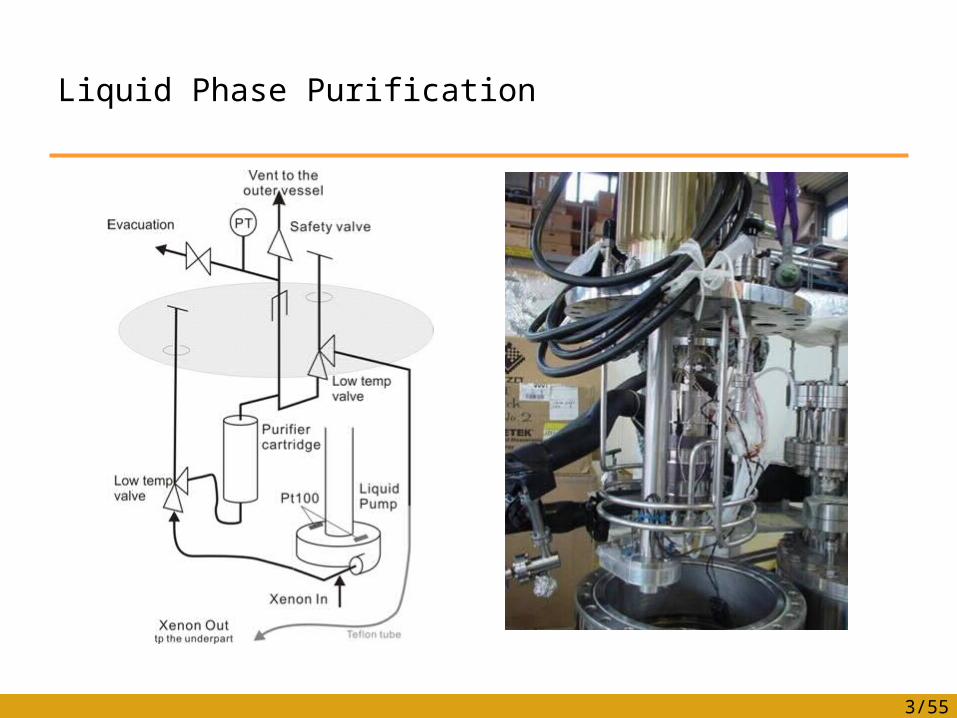
Liquid Phase Purification
4/55
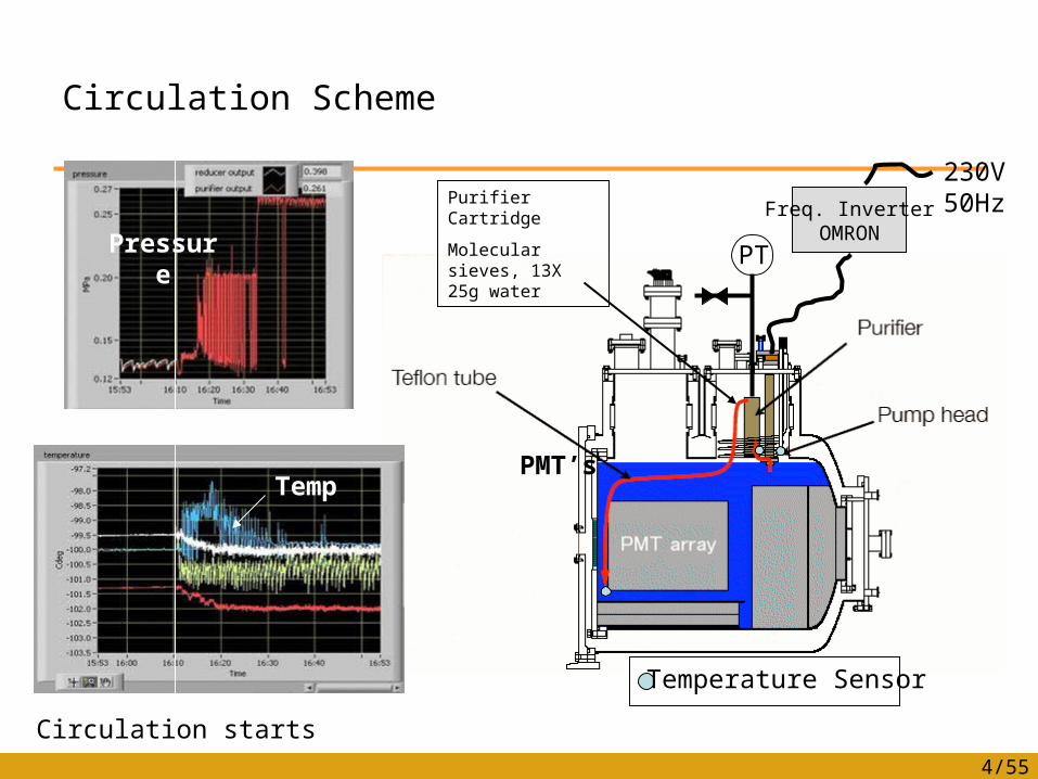
Circulation Scheme
230V50Hz
Pressure
Temperature Sensor
PMT’s
Purifier Cartridge
Molecular sieves, 13X 25g water
Freq. InverterOMRON
PT
Temp
Circulation starts
5/55
Specification
• Purifier cartridge• 500cc cartridge filled with Molecular sieves (13X)
(1/16inch pellet type, 25g water can be absorbed)• The cartridge can be regenerated by heating before
operation (Watlow heater)
• Pump• Centrifugal low temperature fluid pump (Barber Nichols)• Δp=0.2MPa• 53Hz operation, 3175rpm• 100liter/hour, 5000 hours operation more than 600
times purification cycle of 800 liter xenon
6/55
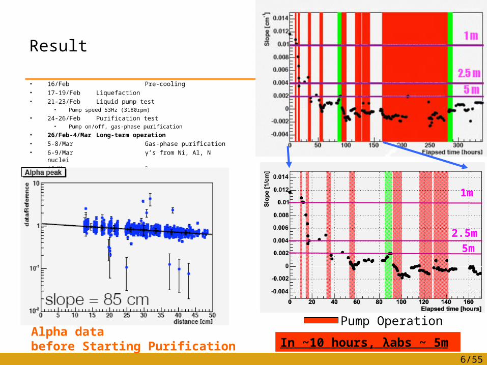
Result
• 16/Feb Pre-cooling• 17-19/Feb Liquefaction• 21-23/Feb Liquid pump test
• Pump speed 53Hz (3180rpm)
• 24-26/Feb Purification test• Pump on/off, gas-phase purification
• 26/Feb-4/Mar Long-term operation• 5-8/Mar Gas-phase purification• 6-9/Mar γ’s from Ni, Al, N nuclei• 10/Mar Recovery
Alpha databefore Starting Purification
Pump Operation
In ~10 hours, λabs ~ 5m
1m
2.5m
5m
7/55
Comments and Remarks
• During evacuation before liquefaction, liquid nitrogen pipe was cooled to keep water contamination in the cryostat.
• Contamination level is calculated to be > 150ppb.
• Liquid level was monitored by measuring temperature above the pump head.
• 52W cooling power is usually required to operate the LP. When the pump is operated, 2.4 times cooling power was needed (estimated with LN2 consumption rate) 62W additional heat load.
• ΔPV = 0.2 MPa x 100 liter/h = 55W
8/55
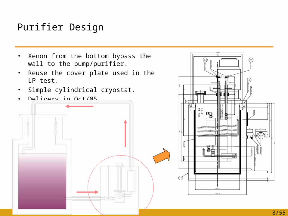
Purifier Design
• Xenon from the bottom bypass the wall to the pump/purifier.
• Reuse the cover plate used in the LP test.• Simple cylindrical cryostat.• Delivery in Oct/05.

PMT R&D Final Report
10/55
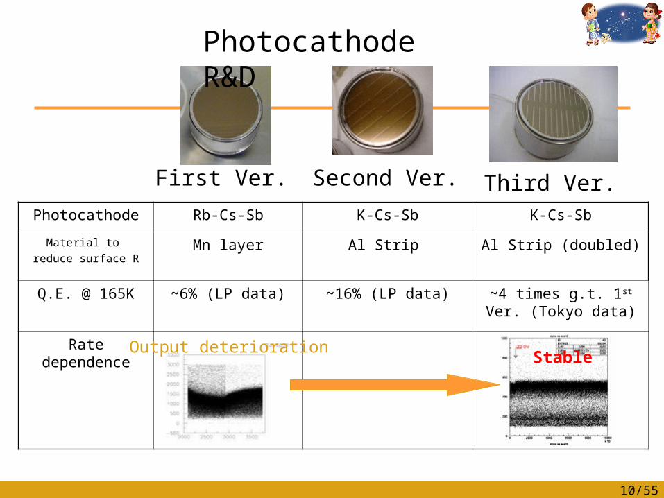
First Ver. Second Ver. Third Ver.Photocathode Rb-Cs-Sb K-Cs-Sb K-Cs-Sb
Material to reduce surface R
Mn layer Al Strip Al Strip (doubled)
Q.E. @ 165K ~6% (LP data) ~16% (LP data) ~4 times g.t. 1st Ver. (Tokyo data)
Rate dependence
Photocathode R&D
StableOutput deterioration
11/55
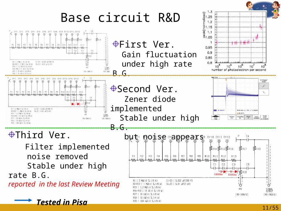
Base circuit R&D
First Ver. Gain fluctuation under high rate B.G.
Second Ver. Zener diode implemented Stable under high B.G. but noise appears
Third Ver. Filter implemented noise removed Stable under high rate B.G.reported in the last Review Meeting
Tested in Pisa

12/55
Optimum resistance is ~100KOhm, Let’s test !
Low pass filter is built in by adding resistors serial to Zener
If the resistance is too small, filtering will not work.
With too large resistance, the effect of Zener will be little under high rate BG environment
Test the power of the filter by changing the resistance Test the gain stability under high rate B.G.
(i.e. rate dependence test)
Mission : Finalize the low pass filter design
13/55
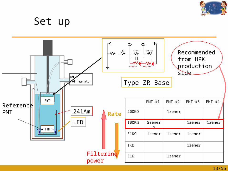
Set up
241Am
LED
Reference PMT
Type ZR Base
PMT #1 PMT #2 PMT #3 PMT #4
200KΩ 1zener
100KΩ 5zeners 1zener 1zener
51KΩ 1zener 1zener 1zener
1KΩ 1zener
51Ω 1zener
Recommended from HPK production side
Filteringpower
Rate
14/55
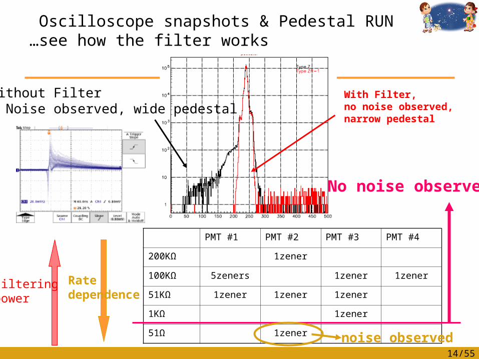
Oscilloscope snapshots & Pedestal RUN …see how the filter works
Without Filter … Noise observed, wide pedestal
With Filter, no noise observed,narrow pedestal
PMT #1 PMT #2 PMT #3 PMT #4
200KΩ 1zener
100KΩ 5zeners 1zener 1zener
51KΩ 1zener 1zener 1zener
1KΩ 1zener
51Ω 1zener
Filteringpower
Ratedependence
No noise observed
noise observed
15/55
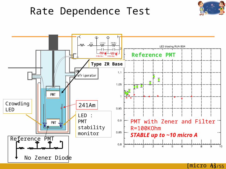
Rate Dependence Test
241Am
LED :PMT stability monitor
Reference PMT
Type ZR Base
CrowdingLED
No Zener Diode
Reference PMT
PMT with Zener and FilterR=100KOhmSTABLE up to ~10 micro A
[micro A]
16/55
Summary of PMT R&D
• Photocathode• We finalized photocathode R&D last year; K-Cs-Sb + AL strip
• Base Circuit• Zener diode was added to reduce voltage drop under high rate background w/o
increasing heat load from the registers (2nd version base).• PMT performance improved against high rate but unacceptable noise appeared.• Possible solution to the problem of noise from Zener diode was presented in the
last review meeting ;
Implementation of Low pass filter to base circuit (3rd Version base).
• We confirmed that with the 3rd version base circuit, noise from Zener diode is successfully removed and PMTs show good performance under high rate B.G. environment.
The design of PMT has thus been finalized.• The results are quickly reported to HPK, and they have started the base
circuit production in March.• Now, PMTs for the final detector are being delivered to PSI and Pisa.
Detector Preparation Status
•Cryostat construction•1000 liter dewar•Xenon transfer
•Gas phase purifier•Liquid/gas transfer
•PMT test at Pisa and PSI•Pi0 calibration
•NaI detector stage•Hydrogen target
•Xenon
18/55
•Tenders and procurements.•Cold joints.•Window status.•Internal structure.
Cryostat Status

19/55
Tenders and procurements
Tenders have been organized in three parts:1. Conventional part2. Purchasing of the cold sealing3. Cold and warm windows
SIMIC (http://www.simic.it) has won the tender (1) for the best price and for other reasons.This company is going to purchase a low magnetic permeability stainless steel (<1.008). Furthermore they are going to perform the cold test at the company.
20/55
Tenders and procurements
However…• The company had a lot of trouble to find the material with the specified magnetic permeability. They tried several
commercial material with no success.• We suggest them to heat treated the stainless steel and they obtain an improvement of magnetic permeability with the
316L.• The material did not meet the specification. Up now they found only the material for the big flanges.
• Low magnetic permeability is achieved when the material are in fully annealed condition bellow 1.02 at 0.02 T (200 G)
• A special material with low magnetic permeability can be obtained, but the time was more them six month, with min quantity of 50 ton.
• We know that nickel help to form the austenitic phase that is not ferromagnetic and we found that the AISI 310 have a nickel content higher than the 316L (19-22 % versus 10-14%).
Finally SIMIC checked the permeability and now they are trying to acquire all material before August to recovery the time lost. (Estimated delivery date is the end of 2005 at PSI.)
We are going to visit them at the end of July to check if the have the material and they promise us to start cutting the material in the first week of August. So the welding and the machining of the parts is taking place in September October.
21/55
Our worries on the schedule
Our worries are that SIMIC can not respect the preliminary planningthat was sent us, in which the cryostat will be at PSI at the end of 2005.The reasons are the following:• Machining and welding can be done in 2 months.• Testing the separated parts and assembling them take more than 3
months, even if everything goes well. • SIMIC has to do mechanical test and leak test of the inner vessel
and the vacuum vessel separately. • After that SIMIC has to mount two vessel together with installing
the instrumentation and the super insulation.• SIMIC has to check the additional welding and do cold and leak
tests. Those operations are not simple and require additional tooling and time.

22/55
Cold joints.
We inquire the specification to three companies:Those companies are specialized in metallic sealing.
• GARLOCK GmbH• High Tech Metal Seals N.V. • Advanced Products NV Parker Seal Group Europe
• We should have the metallic sealing end of October.
23/55
Window status
We inquire the specification to three companies for the metallic part:• Zanon• Cinel• SIMICWe are going to supply the material to the companies to build the teststructure.
We inquire the specification to three companies for the honycomb:• Plyform• RAV• SALVER
We should have the windows at the end of October.

24/55
Window studies
• The heat treatment of the material was studied in collaboration with the metallurgic department of Mechanical and Nuclear engineering of Pisa.
• Several mechanical tests were done and several thermal cycles were made to study the hardening of the material.
• We sent the specification to the companies for building the windows (leaving three option for the construction to be discussed).
25/55
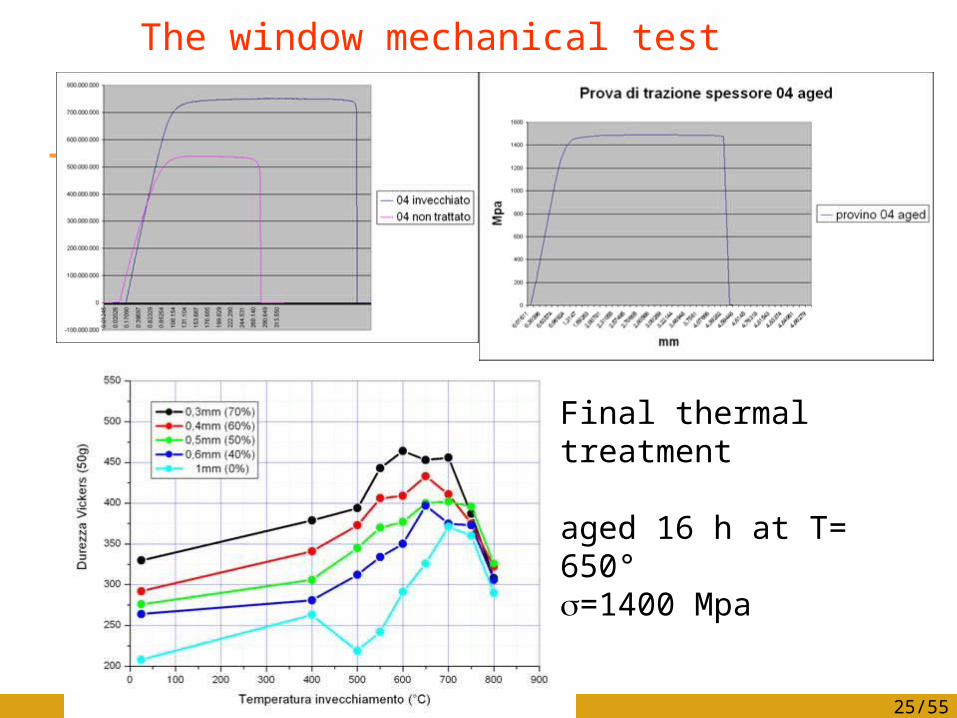
The window mechanical test
Final thermal treatment
aged 16 h at T= 650°=1400 Mpa

26/55
The Internal structure
Radial holes
Centering system for the lateral structure
We try to simplify the machining of the arcs to make them more precise. We need to make some more iteration in our group to discuss about some issues like cabling.
27/55
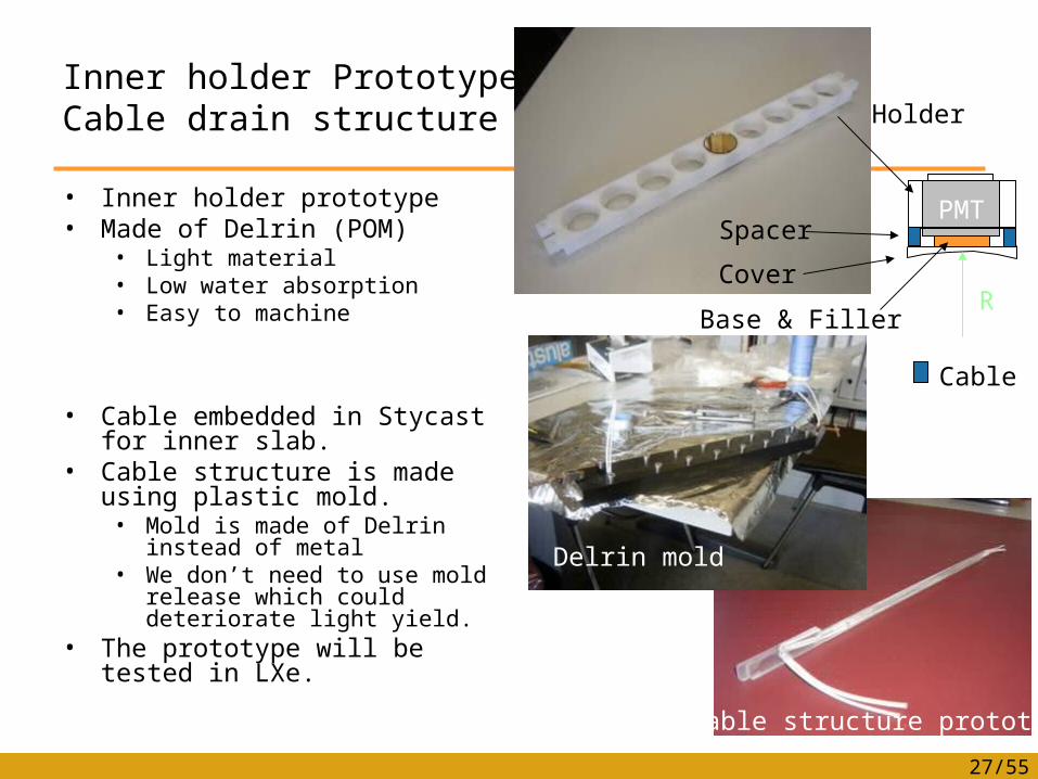
Inner holder PrototypeCable drain structure
• Inner holder prototype• Made of Delrin (POM)
• Light material• Low water absorption• Easy to machine
• Cable embedded in Stycast for inner slab.
• Cable structure is made using plastic mold. • Mold is made of Delrin instead
of metal• We don’t need to use mold
release which could deteriorate light yield.
• The prototype will be tested in LXe.
Delrin mold
Cable structure prototype
PMT
Holder
Cover
Spacer
RBase & Filler
Cable
28/55
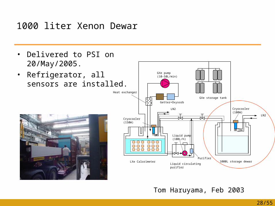
1000 liter Xenon Dewar
• Delivered to PSI on 20/May/2005.
• Refrigerator, all sensors are installed.
LXe CalorimeterLiquid circulating purifier
Liquid pump (100L/h)
Purifier1000L storage dewar
Cryocooler (100W)
LN2
LN2
Getter+Oxysorb
GXe pump (10-50L/min)
GXe storage tank
Cryocooler (150W)
Heat exchanger
Tom Haruyama, Feb 2003
29/55
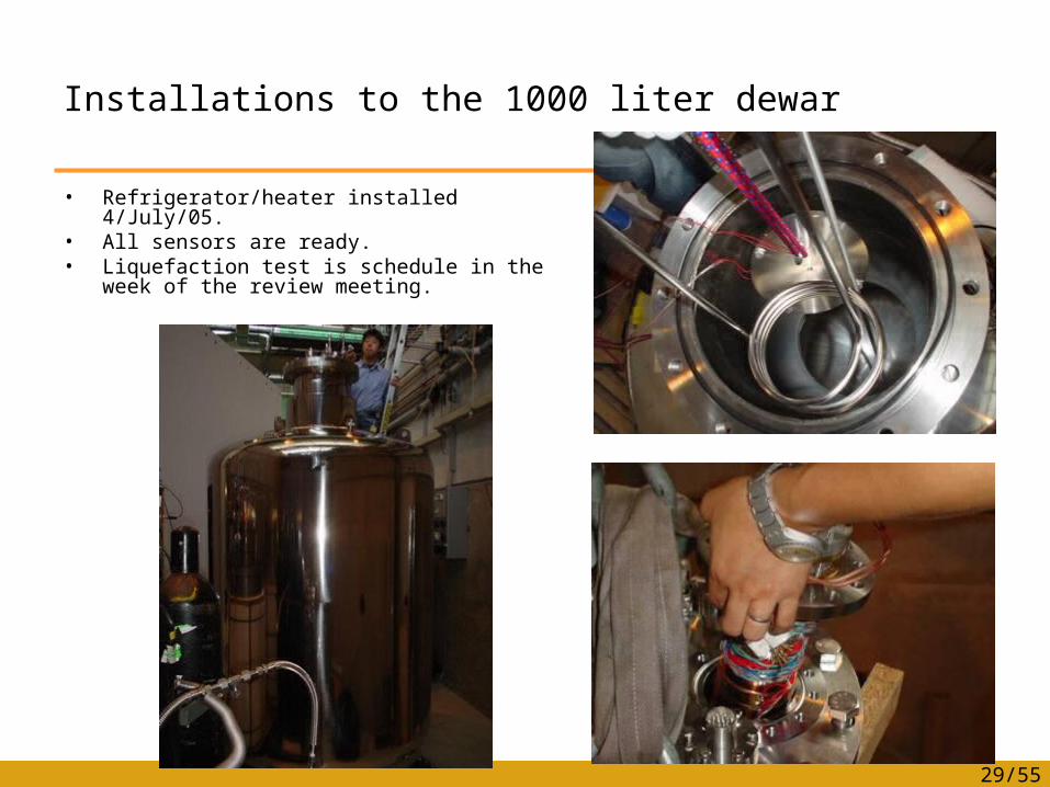
Installations to the 1000 liter dewar
• Refrigerator/heater installed 4/July/05.• All sensors are ready.• Liquefaction test is schedule in the week
of the review meeting.
30/55
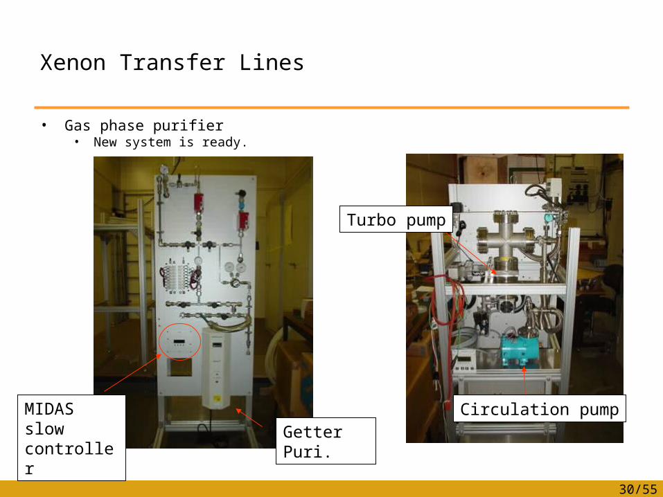
Xenon Transfer Lines
• Gas phase purifier• New system is ready.
MIDAS slow controller Getter Puri.
Turbo pump
Circulation pump
31/55
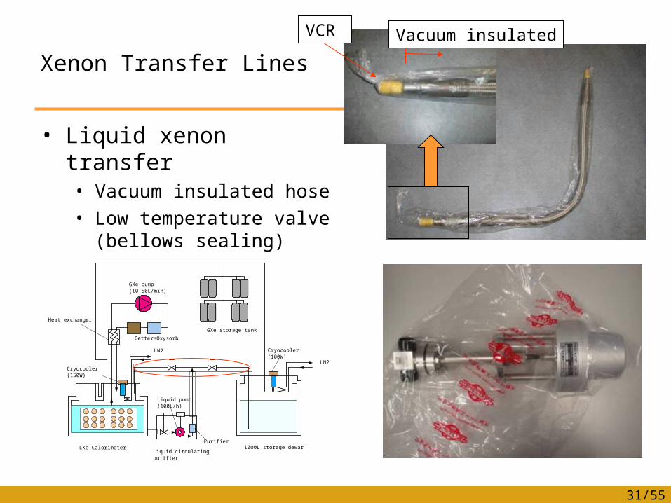
Xenon Transfer Lines
• Liquid xenon transfer• Vacuum insulated hose• Low temperature valve
(bellows sealing)
LXe CalorimeterLiquid circulating purifier
Liquid pump (100L/h)
Purifier1000L storage dewar
Cryocooler (100W)
LN2
LN2
Getter+Oxysorb
GXe pump (10-50L/min)
GXe storage tank
Cryocooler (150W)
Heat exchanger
Vacuum insulatedVCR

PMT test status
33/55
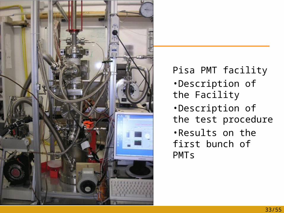
Pisa PMT facility•Description of the Facility•Description of the test procedure•Results on the first bunch of PMTs
34/55
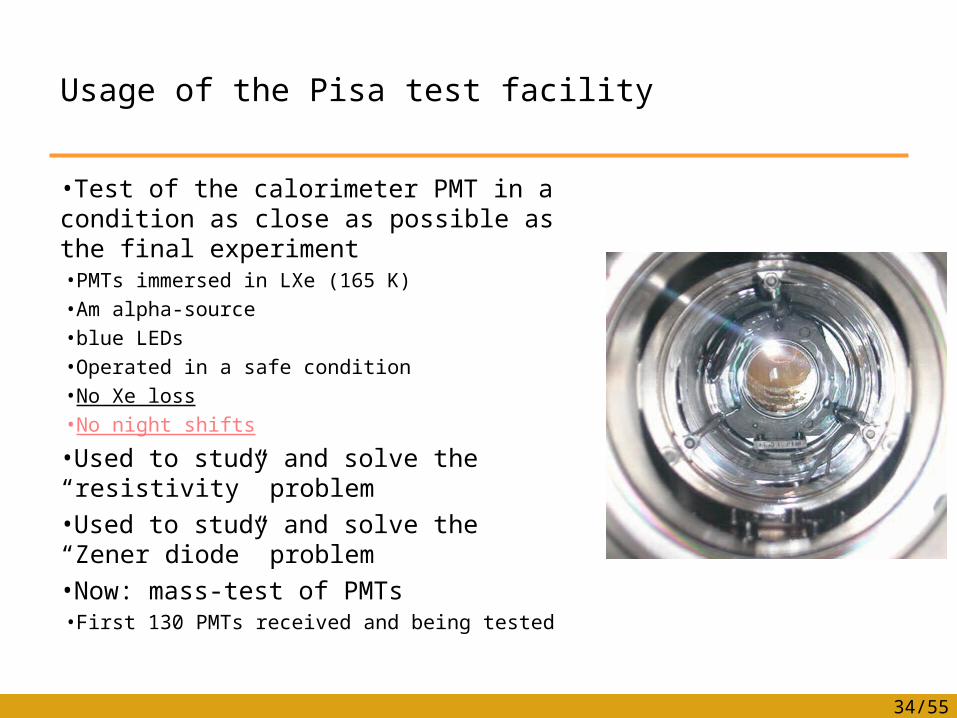
Usage of the Pisa test facility
•Test of the calorimeter PMT in a condition as close as possible as the final experiment•PMTs immersed in LXe (165 K) •Am alpha-source•blue LEDs•Operated in a safe condition•No Xe loss•No night shifts
•Used to study and solve the “resistivity” problem•Used to study and solve the “Zener diode” problem•Now: mass-test of PMTs•First 130 PMTs received and being tested
35/55
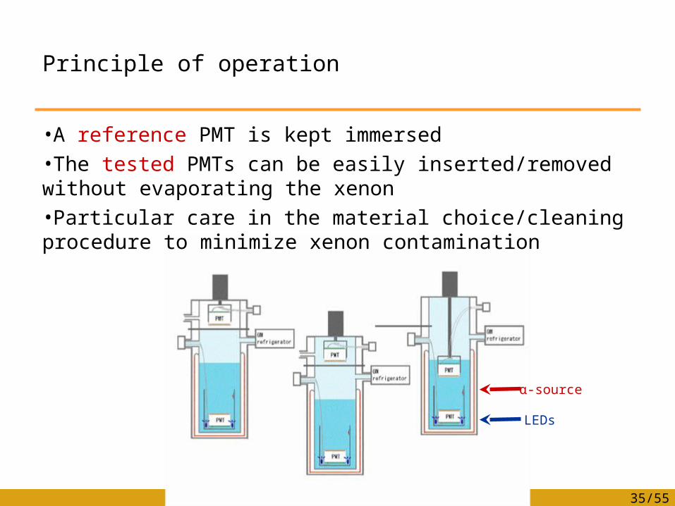
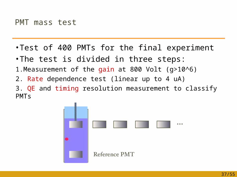
Principle of operation
•A reference PMT is kept immersed •The tested PMTs can be easily inserted/removed without evaporating the xenon•Particular care in the material choice/cleaning procedure to minimize xenon contamination
α-sourceα-source
LEDsLEDs
36/55
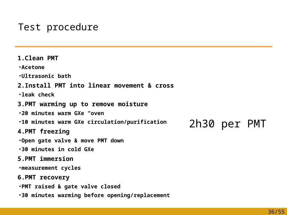
Test procedure
1.Clean PMT•Acetone
•Ultrasonic bath
2.Install PMT into linear movement & cross•leak check
3.PMT warming up to remove moisture•20 minutes warm GXe “oven”
•10 minutes warm GXe circulation/purification
4.PMT freezing•Open gate valve & move PMT down
•30 minutes in cold GXe
5.PMT immersion•measurement cycles
6.PMT recovery•PMT raised & gate valve closed
•30 minutes warming before opening/replacement
2h30 per PMT2h30 per PMT
37/55
PMT mass test
•Test of 400 PMTs for the final experiment•The test is divided in three steps:1.Measurement of the gain at 800 Volt (g>10^6)2. Rate dependence test (linear up to 4 uA)3. QE and timing resolution measurement to classify PMTs
38/55
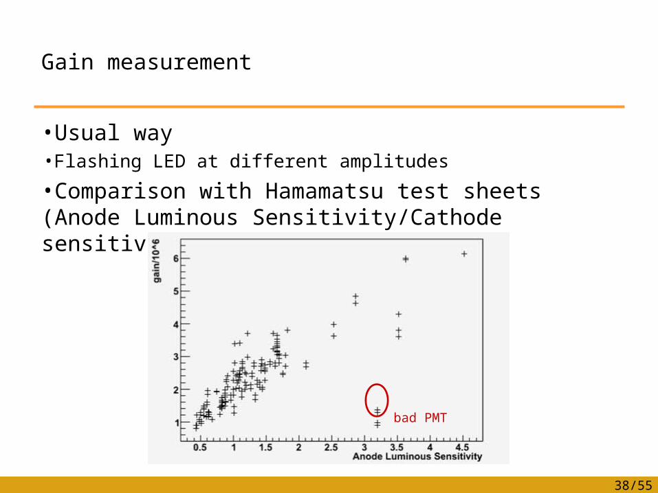
Gain measurement
•Usual way•Flashing LED at different amplitudes
•Comparison with Hamamatsu test sheets (Anode Luminous Sensitivity/Cathode sensitivity)
bad PMTbad PMT
39/55
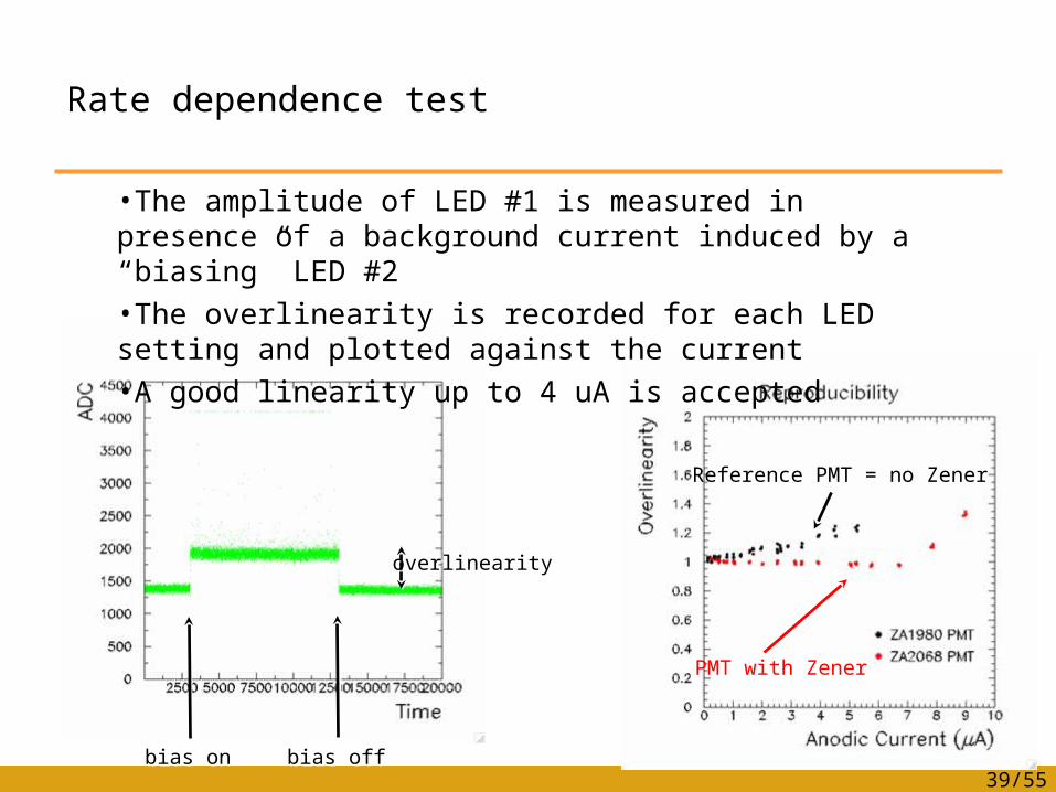
Rate dependence test
Reference PMT = no Zener
PMT with Zener
bias onbias on bias offbias off
overlinearityoverlinearity
•The amplitude of LED #1 is measured in presence of a background current induced by a “biasing” LED #2•The overlinearity is recorded for each LED setting and plotted against the current •A good linearity up to 4 uA is accepted
40/55
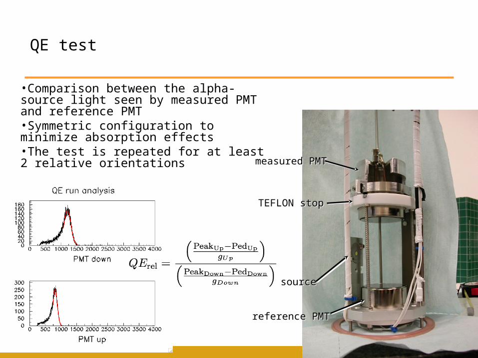
QE test
•Comparison between the alpha-source light seen by measured PMT and reference PMT•Symmetric configuration to minimize absorption effects•The test is repeated for at least 2 relative orientations
TEFLON stopTEFLON stop
sourcesource
measured PMTmeasured PMT
reference PMTreference PMT
41/55
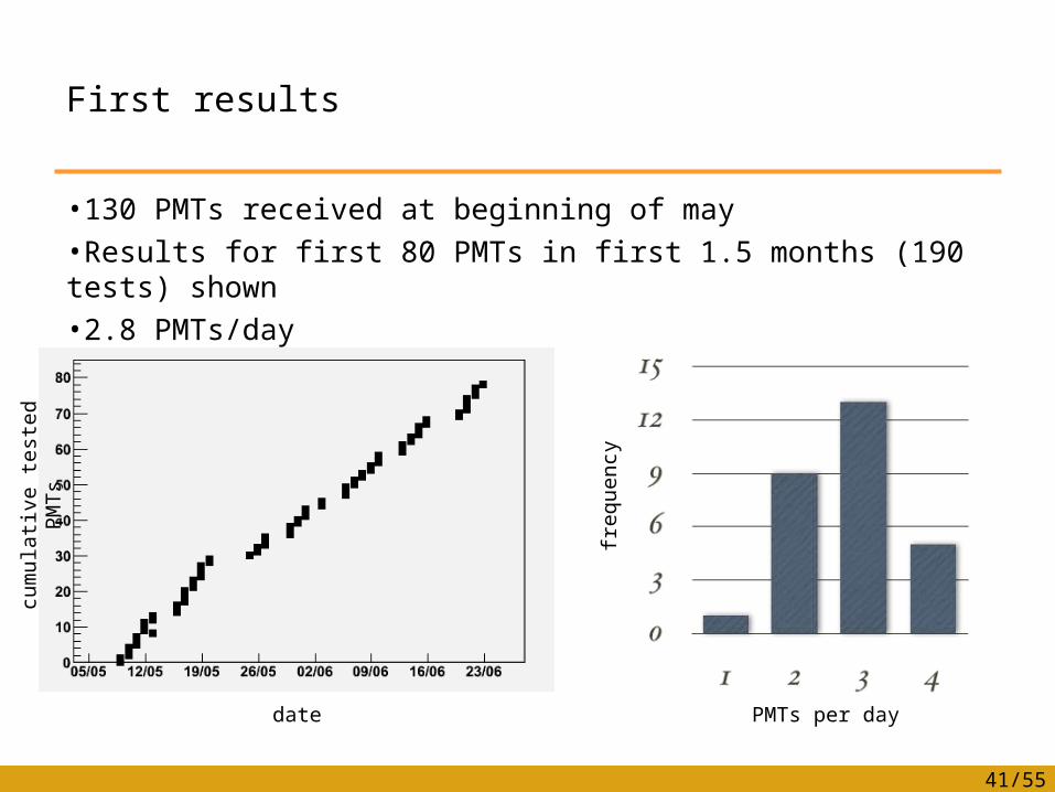
First results
•130 PMTs received at beginning of may•Results for first 80 PMTs in first 1.5 months (190 tests) shown•2.8 PMTs/day
cum
ula
tive t
est
ed
PM
Ts
cum
ula
tive t
est
ed
PM
Ts
datedate PMTs per dayPMTs per day
frequency
frequency
42/55
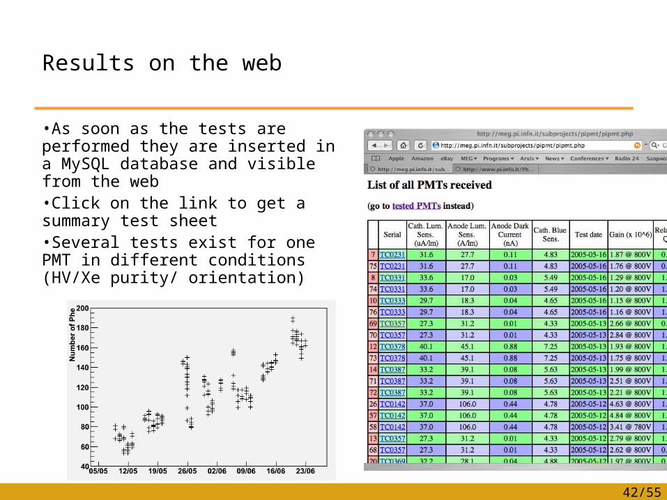
Results on the web
•As soon as the tests are performed they are inserted in a MySQL database and visible from the web•Click on the link to get a summary test sheet•Several tests exist for one PMT in different conditions (HV/Xe purity/ orientation)
43/55
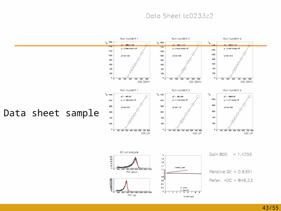
Data sheet sample
44/55
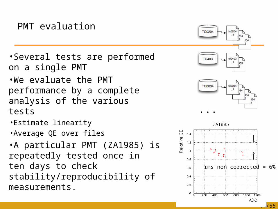
PMT evaluation
•Several tests are performed on a single PMT•We evaluate the PMT performance by a complete analysis of the various tests•Estimate linearity•Average QE over files
•A particular PMT (ZA1985) is repeatedly tested once in ten days to check stability/reproducibility of measurements.
......
rms non corrected = 6%rms non corrected = 6%
45/55
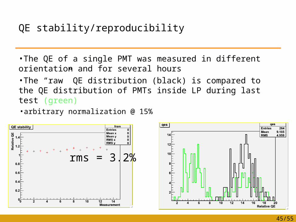
QE stability/reproducibility
•The QE of a single PMT was measured in different orientation and for several hours•The “raw” QE distribution (black) is compared to the QE distribution of PMTs inside LP during last test (green) •arbitrary normalization @ 15%
rms = 3.2%rms = 3.2%
46/55
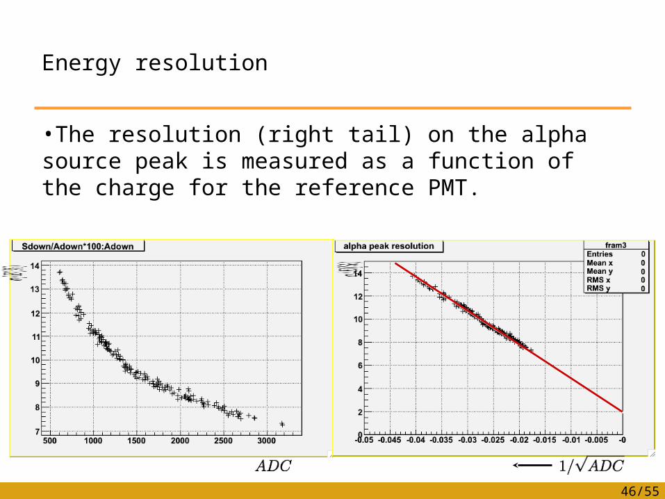
Energy resolution
•The resolution (right tail) on the alpha source peak is measured as a function of the charge for the reference PMT.
•The resolution (right tail) on the alpha source peak is measured as a function of the charge for the reference PMT.

47/55
Timing resolution
•The timing resolution of each PMT is measured with alpha source
•Quite well reproduced by data
48/55
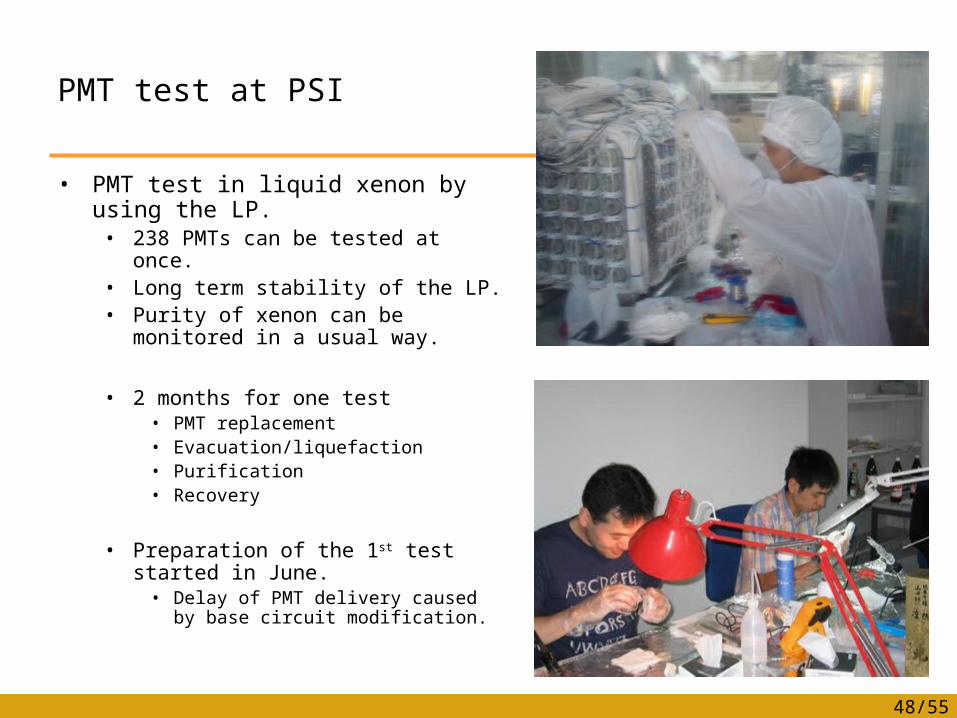
PMT test at PSI
• PMT test in liquid xenon by using the LP.• 238 PMTs can be tested at once.• Long term stability of the LP.• Purity of xenon can be monitored
in a usual way.
• 2 months for one test• PMT replacement• Evacuation/liquefaction• Purification• Recovery
• Preparation of the 1st test started in June.
• Delay of PMT delivery caused by base circuit modification.
49/55
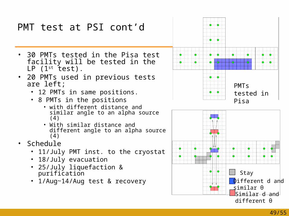
PMT test at PSI cont’d
• 30 PMTs tested in the Pisa test facility will be tested in the LP (1st test).
• 20 PMTs used in previous tests are left;• 12 PMTs in same positions.• 8 PMTs in the positions
• with different distance and similar angle to an alpha source (4)
• With similar distance and different angle to an alpha source (4)
• Schedule• 11/July PMT inst. to the cryostat• 18/July evacuation• 25/July liquefaction & purification• 1/Aug~14/Aug test & recovery
PMTs tested in Pisa
Stay
Different d andsimilar θSimilar d anddifferent θ
50/55
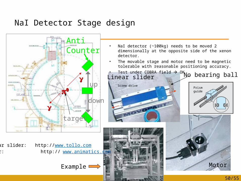
NaI Detector Stage design
• NaI detector (~100kg) needs to be moved 2 dimensionally at the opposite side of the xenon detector.
• The movable stage and motor need to be magnetic tolerable with reasonable positioning accuracy.
• Test under COBRA field OK
Anti Counter
up
down
target
00
Linear slider
Motor
No bearing ball
Prism guideScrew drive
Example
Linear slider: http://www.tollo.comMotor: http:// www.animatics.com
51/55
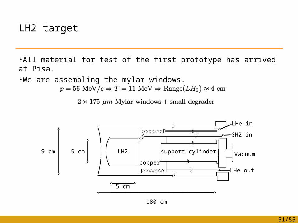
LH2 target
•All material for test of the first prototype has arrived at Pisa.•We are assembling the mylar windows.
9 cm9 cm 5 cm5 cm
5 cm5 cm
180 cm180 cm
LH2LH2
coppercopper
support cylindersupport cylinder
LHe inLHe in
LHe outLHe out
GH2 inGH2 in
VacuumVacuum

52/55
Xenon
• We have 850 liter at PSI !• 100 liter is on the way!!

Analysis Update
54/55
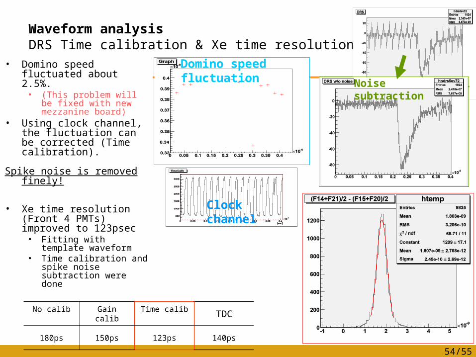
Waveform analysisDRS Time calibration & Xe time resolution
• Domino speed fluctuated about 2.5%.
• (This problem will be fixed with new mezzanine board)
• Using clock channel, the fluctuation can be corrected (Time calibration).
Spike noise is removed finely!
• Xe time resolution (Front 4 PMTs) improved to 123psec
• Fitting with template waveform
• Time calibration and spike noise subtraction were done
Domino speed fluctuation
No calib Gain calib Time calib TDC
180ps 150ps 123ps 140ps
Clock channel
Noise subtraction
55/55
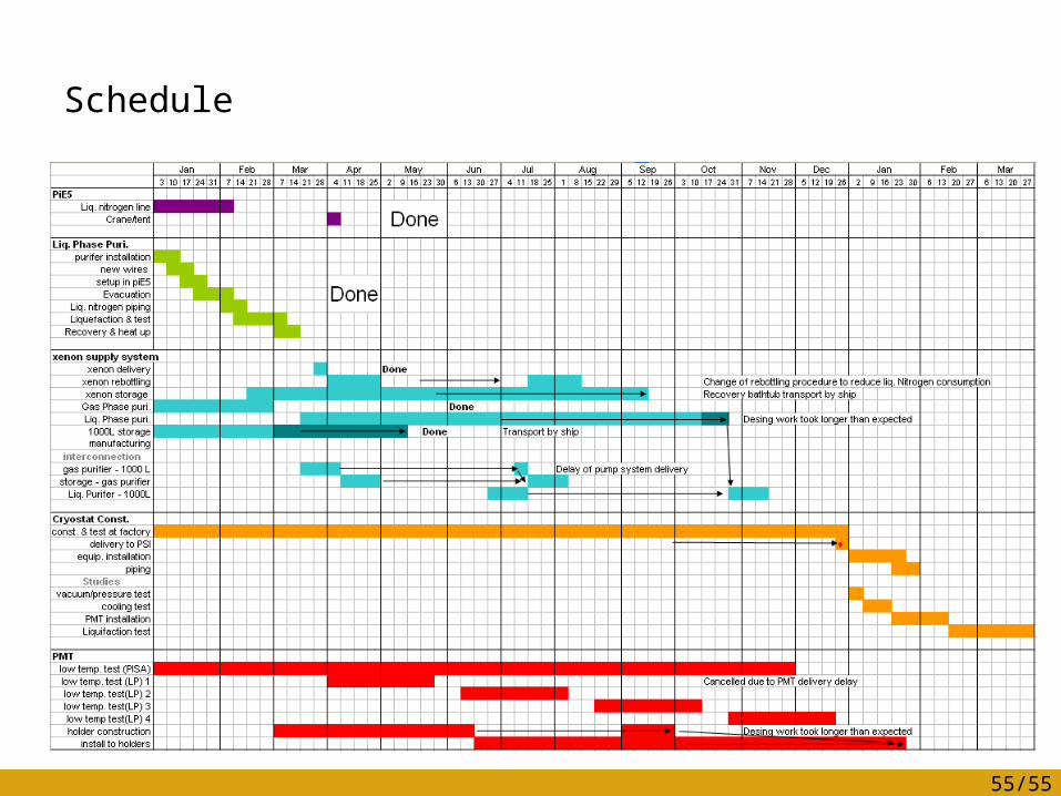
Schedule