keysight technologies usb modular productsliterature.cdn.keysight.com/litweb/pdf/5989-9923en.pdf ·...
TRANSCRIPT

Keysight Technologies USB Modular Products
Data Sheet

IntroductionThe Keysight Technologies Inc. compact USB modular products are a series of modules that are flexible to be used standalone or plugged into a compatible chassis to make synchronized measurements as a modular unit. Essential measurements can be made with a laptop PC and these modules through USB high-speed 2.0 connections. Through individual windows, the Keysight Measurement Manager (KMM) software provides a friendly soft front-panel interface for each of the modular products. This helps to perform quick configuration and measurement acquisition as well as flexible analysis of measured data.
Simple setup with USB Hi-Speed 2.0 and bundled software
Easy to program with KMM software, IVI drivers, and a wide range of Application Development Environment compatibility
Portable and compact Flexibility with standalone/modular capability

3
Overview
Table of Contents
Overview ......................................................................................3
Keysight U2781A USB Modular Product Chassis ....................7
Keysight Measurement Manager ............................................ 12
Keysight USB Modular Data Acquisition Modules ................ 13
U2300A Series USB Modular Multifunction Data Acquisition Devices .............................................................. 14
U2500A Series USB Modular Simultaneous Sampling Multifunction DAQ Devices ................................................. 25
U2600A Series USB Modular Isolated Digital I/O Devices ................................................................................. 33
U2802A 31-Channel Thermocouple Input Device ............ 37 Optional Acessories for USB Modular DAQ ........................ 44
Keysight USB Modular Test Instrument Modules ................. 46
U2701A and U2702A USB Modular Oscilloscope ............. 47 U2722A/U2723A USB Modular Source Measure Unit ..... 54 U2741A USB Modular Digital Multimeter .......................... 58 U2751A USB Modular Switch Matrix ................................. 64
U2761A Function/Arbitrary Waveform Generator ............ 68
Ordering Information ............................................................... 74
Keysight U2781A USB Modular Product Chassis
Features: – Expansion of channels for each modular products – Multiple instrument synchronization – Internal and external 10 MHz reference clock – High-speed USB 2.0 – SSI/Star trigger bus synchronization between
external trigger source and modules
Keysight Measurement Manager
The Keysight Measurement Manager is a bundled software that comes with the standard purchase of a USB modular DAQ, USB modular instrument, or the U2781A USB modular product chassis.

4
Keysight USB Modular Data Acquisition (DAQ) Family
U2300A Series USB Modular Multifunction DAQ
U2600A Series USB Modular Isolated Digital I/O
Features: – High analog input sampling rate coverage of up to
3 MSa/s for a single channel – High analog input up to 64 channels – High speed USB 2.0 – Multifunction capabilities — analog input (AI), analog output
(AO), digital input output (DIO), and counter
Features: – 64 opto-isolated lines that can meet demand up to 24 V – High speed USB 2.0 – Isolation voltage of 1250 Vrms for protection from transient
voltage spikes
U2500A Series USB Modular Simultaneous Sampling
Multifunction DAQ
Signal Conditioner U2802A 31-Channel
Thermocouple Input Device
Features: – High analog input sampling rate coverage of up to
2 MSa/s for a each channel – High speed USB 2.0 – Simultaneous acquisition of multiple data points – Multifunction capabilities — analog input (AI), analog output
(AO), digital input output (DIO), and counter
Features: – 31 input channels that can be independently configured – Error detection for open thermocouple channels – Built-in isothermal construction on terminal block – Auto-zeroing function – Works with U2355A and U2356A USB modular DAQ
Optional Accessories
Features: – U2901A and U2902A terminal block and SCSI-II 68-pin
connector with 1-meter/2-meter cable for U2300A Series and U2500A Series
– U2903A and U2904A terminal block and SCSI-II 100-pin connector with 1-meter/2-meter cable for U2600A Series

5
Keysight USB Modular Test Instruments Family
U2701A/U2702A USB Modular Oscilloscope
U2741A USB Modular Digital Multimeter (DMM)
U2722A/U2723A USB Modular Source Measure Unit
U2751A USB Modular Switch Matrix
U2761A USB Modular Function/Arbitrary Waveform
Generator
Features: – High sampling rate up to 500 MSa/s, enables accurate
measurement analysis – Up to 32 MB large memory – Fast fourier transfer (FFT) and waveform math functions
enables easy waveform calculation
Features: – Fast reading speed (up to 100 Sa/s) – Wide range of basic measurement functions, including
frequency and temperature measurements
Features: – Four-quadrant source/measure operation – 16-bit resolution for all voltage and current ranges with high
measurement sensitivity – High accuracy – Embedded test script (for U2723A) – IV Curve application support in Keysight Measurement
Manager (for U2723A) – Faster rise/fall time (for U2723A)
Features: – Minimal cross-talk of –30 dB at 45 MHz wide bandwidth – High bandwith at 45 MHz without terminal block – Capability to test up to four devices-under-test (DUTs) – Works with other Keysight instruments for multi-point
testing
Features: – Direct digital synthesis (DDS) waveform generator – Pulse generator that can generate pulse signal as stimulus – Easy customization with Arbitrary Waveform Editor – Internal modulation capability simplifies test setup

6
Compatible with a Wide Range of Application Development EnvironmentsThe Keysight USB modular products are compatible with a wide range of application development environments. This minimizes the time that R&D and manufacturing engineers need to use the devices in different software environments.
Listed below are the popular development environments and tools with which the USB modular oscilloscope is compatible:
– Keysight VEE and Keysight T&M Toolkit – Microsoft Visual Studio.NET, C/C++, and Visual Basic 6 – MATLAB – LabVIEW – Microsoft .NET Framework
Ease of UseThe Keysight USB modular products are equipped with Hi-Speed USB 2.0 interfaces for easy setup, plug-and-play, and hot swappable connectivity. With the quick and easy USB connectivity, the USB modular products are simple enough for academic applications and yet robust and versatile enough for industriallaboratory applications. Simplifying this further is the Keysight Measurement Manager software that offers a simple interface for quick setup, configuration, and measurement control.
Flexible Standalone or Modular CapabilityThe USB modular products are uniquely designed for the flexibility of functioning as a standalone or modular unit. You can reduce your startup cost by using the USB modular product as a standalone unit. On the other hand, using the USB modular product as a modular unit, you will be able to expand your application system — in terms of channel count and functionality — by slotting in various modular units into the U2781A.
Easy-to-use bundled software and the command logger functionThe Keysight Measurement Manager application software provides you with a quick and easy means to configure and control your device without requiring any programming work. Simplifying this further is the command logger function offered in the Keysight Measurement Manager that allows capturing of configuration commands that can be easily converted to snippets of VEE code. Other supported languages are VB, C++, and C#.
Modules LabView LabWindows/CVI MatLab IVI SCPI
U2300A Series USB Modular Multifunction DAQ
U2500A Series USB Modular Simultaneous Sampling Multi-function DAQ
U2600A Series USB Modular Isolated Digital I/O
U2701A/U2702A USB Modular Oscilloscope
U2722A/U2723A USB Modular Source Measure Unit
U2741A USB Modular Digital Multimeter (DMM)
U2751A USB Modular Switch Matrix
U2761A USB Modular Function/Arbitrary Waveform Generator

7
IntroductionThe Keysight U2781A USB modular product chassis is a high-performance 4U chassis that comes with a 200 W universal AC power supply and a built-inprotection circuit. This portable chassis can house up to six Keysight USBmodular products. The U2781A targets a wide range of applications in bothindustrial and scientific environments in the research and development (R&D),design-validation, and manufacturing fields. The primary advantage of thischassis is its synchronization capability between modules. This can help youto lower your cost of testing and accelerate your test system integration anddevelopment.
The U2781A is equipped with an internal 10 MHz reference clock for eachmodule slot. There are two temperature sensors to monitor the internaltemperature and a built-in fan to maintain the internal temperature. The triggerbus enables the USB modular products to trigger signals to each other.
Features
– Internal and external 10 MHz reference clock
– Simultaneous Synchronization Interface (SSI)
– Star trigger – External trigger-in and trigger-out
signals – Temperature and fan speed
monitoring – Compatible with Hi-Speed – USB 2.0 and USBTMC-USB488
standards – Bundled software — Keysight
Measurement Manager (KMM) – Rackmount kit available as an option
Keysight U2781A USB Modular Product Chassis
Supported productsThe chassis supports the following USB modular products:
– USB modular data acquisition (DAQ) including: – U2300 Series USB modular multifunction DAQ devices – U2500 Series USB modular simultaneous sampling multifunction
DAQ devices – U2600 Series USB modular isolated digital I/O devices
– USB modular instruments including: – U2701A/U2702A USB modular oscilloscope – U2722A/U2723A USB modular source measure unit – U2741A USB modular digital multimeter – U2751A USB modular switch matrix – U2761A USB modular function/arbitrary generator

8
Triggering using Star trigger busThe U2781A comes with a Star trigger bus, which offers precise synchronization between USB modular products and the external trigger signal. The star trigger bus provides dedicated trigger lines between the external trigger input and slotted USB modules. You can also achieve precise triggering between each USB modular product via the synchronized routing of the star trigger.
System optionThe U2781A USB modular product chassis has a mountable rackmount kit, which can be ordered separately (see “Optional Accessories” on page 8). This allows for a better setup when the U2781A is integrated into a test system.
Simultaneous Synchronization Interface (SSI) capabilityThe table below shows the USB modular products triggering capability.
Modular products Configure as Master1 Configure as Slave2
U2300A Series Yes Yes
U2500A Series Yes Yes
U2600A Series Yes Yes
U2701A/U2702A3 Yes Yes
U2722A/U2723A3 Yes4 Yes
U2741A No Yes
U2751A No No
U2761A Yes Yes
High-density data acquisitionThe U2781A chassis increases the number of available channels whenany U2300 Series, U2500 Series, or U2600 Series products are slotted into the chassis. For example, when you slot six U2331A Series products in the chassis, it allows for an expansion of up to 384 channels, providing a high-density data acquisition solution.
Internal and external 10 MHz reference clockThe U2781A is equipped with a 10 MHz reference clock. It is used to synchronize the timebase of the USB modular products slot into the chassis for more precise measurements.
Simultaneous Synchronization Interface (SSI)SSI provides synchronization between the modular products in the chassis by allowing the modules to be configured as Master or Slave. The Master module sends the SSI signal to the Slave module via the backplane trigger bus. Then, the Slave module receives the signal and begins synchronization with the Master module. There are two SSI configuration modes available — single Master-multiple Slaves and multiple Masters-multiple Slaves. Please refer to the Keysight U2781A USB Modular Product Chassis User’s Guide for more information.
1 The Master module sends the SSI trigger-out signal to the Slave module via the backplane trigger bus.
2 The Slave module receives the SSI trigger-in signal and begins synchronization with the Master module.
3 U2722A/U2723A cannot trigger U2701A/U2702A and vice versa.4 Triggering can only be done through SCPI command.
9
Product characteristics and general specifications
REMOTE INTERFACE – Hi-Speed USB 2.0* – USBTMC-USB4885
POWER CONSUMPTION – 400 VA maximum – Installation Category II
OPERATING ENVIRONMENT – Operating temperature from 0 °C to +55 °C – Operating humidity at 15% to 85% RH (non-condensing) – Altitude up to 2000 meters – Pollution Degree 2 – For indoor use only
STORAGE COMPLIANCE–20 °C to 70 °C
SAFETY COMPLIANCECertified with:
– IEC 61010-1:2001/EN 61010-1:2001 (2nd Edition) – USA: UL61010-1: 2004 – Canada: CSA C22.2 No.61010-1:2004
EMC COMPLIANCE – IEC/EN 61326-1 1998 – CISPR 11: 1990/EN55011:1991, Class A, Group 1 – Canada: ICES-001:1998 – Australia/New Zealand: AS/NZS 2064.1
ACOUSTIC EMISSION – Sound pressure level: 45.5 dB(A) – Sound power level: 56.6 dB(A)
SHOCK AND VIBRATIONTested to IEC/EN 60068-2
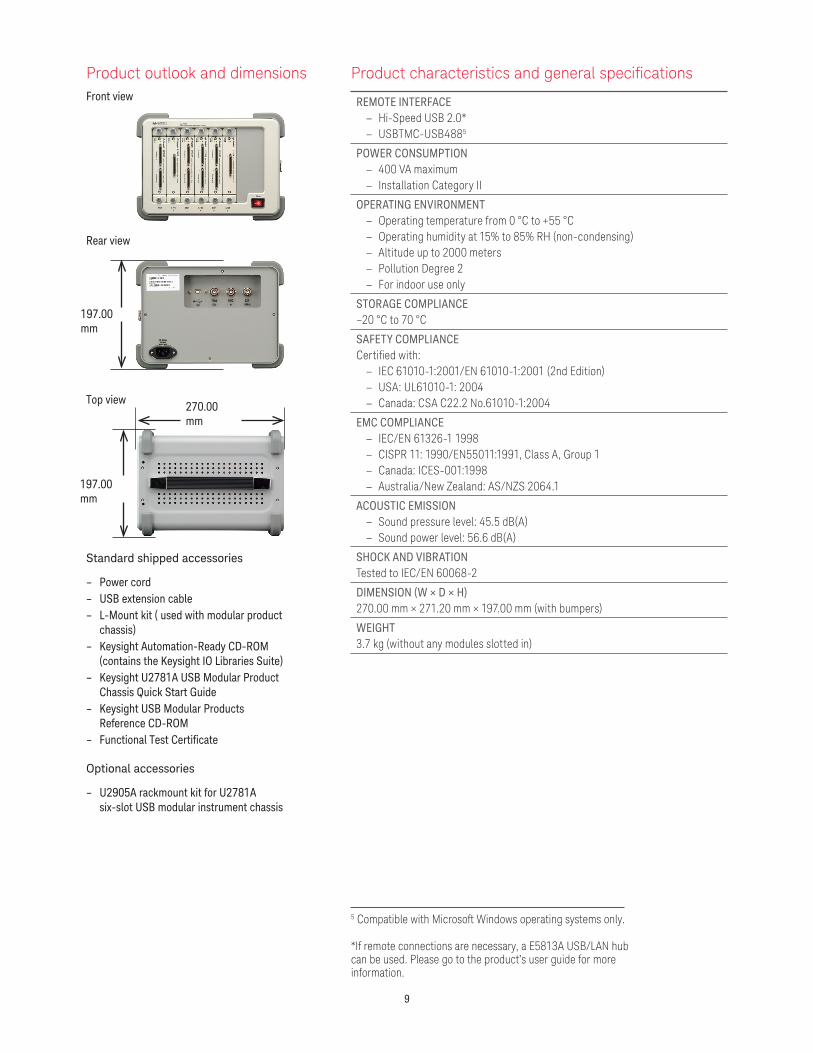
DIMENSION (W × D × H)270.00 mm × 271.20 mm × 197.00 mm (with bumpers)
WEIGHT3.7 kg (without any modules slotted in)
Product outlook and dimensionsFront view
Rear view
Top view
Standard shipped accessories
– Power cord – USB extension cable – L-Mount kit ( used with modular product
chassis) – Keysight Automation-Ready CD-ROM
(contains the Keysight IO Libraries Suite) – Keysight U2781A USB Modular Product
Chassis Quick Start Guide – Keysight USB Modular Products
Reference CD-ROM – Functional Test Certificate
Optional accessories
– U2905A rackmount kit for U2781A six-slot USB modular instrument chassis
197.00 mm
270.00 mm
197.00 mm
5 Compatible with Microsoft Windows operating systems only.
*If remote connections are necessary, a E5813A USB/LAN hub can be used. Please go to the product’s user guide for more information.

10
Electrical specifications
Power supply AC input
Input voltage range 100 to 240 VAC
Input frequency range 50 to 60 Hz
Power consumption 400 VA maximum
Efficiency 75%
Power supply DC output
Output rated voltage 12 VDC
Max output rated current 16.7 A
Max output rated power 200 W
Over voltage protection 13.2 to 16.2 V
Internal 10 MHz reference clock
Accuracy 25 ppm for operating range
Slot to slot skew 350 ps
External 10 MHz reference clock
Auto detection level Yes
Input frequency range 10 MHz
Input magnitude 100 mVpp to 5 Vpp (sine/square wave)
Input impedance 50 Ω ± 5 Ω
Damage level 10 Vrms
External trigger in
Compatibility TTL
VIH (Positive threshold voltage) 2.0 V
VIL (Negative threshold voltage) 0.8 V
Hold time 8 ns pulse width
Input voltage range 0 V to 5.0 V
Slot to slot skew 350 ps
External trigger out
VOH 2.9 V
VOL 0.1 V
Output voltage range 0 V to 3.3 V

11
Mechanical specifications
Physical layout
Number of USB module slots 6
Dimension of each module slot 25.40 mm (W) x 174.54 mm (D) x 105.00 mm (H)
Dimension of chassis 270.00 mm (W) x 271.20 mm (D) x 197.00 mm (H)
Weight 3.7 kg
Power LED ON/OFF type
USB backplane
Connector 55-pin Ethernet male type C
Input signalsExternal 10 MHz clock in (BNC connector)External trigger in (BNC connector)
Output signal Trigger out (BNC connector)
Cooling fan
Number of fans 2
Fan speed 3300 rpm ±10%
Noise 37 dB(A)
Power (each fan) 2.52 W
12
Keysight Measurement Manager PrerequisitesPrior to installing the Keysight Measurement Manager software, ensure that your PC meets the following minimum system requirements for installation and operations.
Hardware Requirements
Processor 1.6 GHz Pentium IV or higher
Operating System One of the following Microsoft Windows versions: – Windows XP Professional or Home edition (Service Pack 1 or later) – Windows Vista 32-bit (Business, Ultimate, Enterprise, Home Basic, and Home Premium edition) – Windows 7 32-bit (Professional, Ultimate, Enterprise, Home Basic, and Home Premium Edition) – Windows 7 (64-bit) support for 32-bit application running on a WOW64 (Windows-on-Windows 64-bit)
emulator.
Hard Disk Space 1 GB
RAM 512 MB or higher recommended
Video Super VGA (800 x 600), 256 colors or more
Software Requirements
– Keysight IO Libraries Suite 15.0 or higher1
– Keysight T&M Toolkit Runtime version 2.12
– Keysight T&M Toolkit Redistributable Package 2.1 patch2
– Microsoft.NET Framework version 2.02
Keysight Measurement Manager
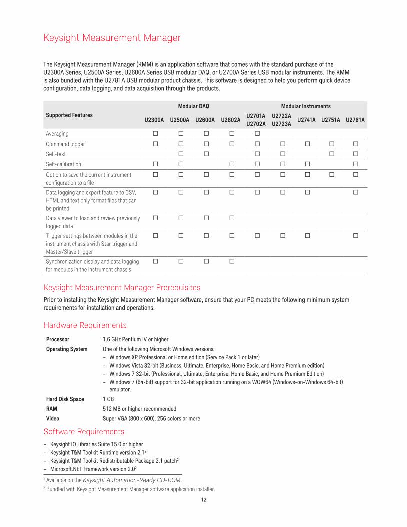
The Keysight Measurement Manager (KMM) is an application software that comes with the standard purchase of the U2300A Series, U2500A Series, U2600A Series USB modular DAQ, or U2700A Series USB modular instruments. The KMM is also bundled with the U2781A USB modular product chassis. This software is designed to help you perform quick device configuration, data logging, and data acquisition through the products.
1 Available on the Keysight Automation-Ready CD-ROM.2 Bundled with Keysight Measurement Manager software application installer.
Supported FeaturesModular DAQ Modular Instruments
U2300A U2500A U2600A U2802AU2701A U2702A
U2722A U2723A
U2741A U2751A U2761A
Averaging
Command logger1
Self-test
Self-calibration
Option to save the current instrument configuration to a file
Data logging and export feature to CSV, HTML and text only format files that can be printed
Data viewer to load and review previously logged data
Trigger settings between modules in the instrument chassis with Star trigger and Master/Slave trigger
Synchronization display and data logging for modules in the instrument chassis
13
Keysight USB Modular Data Acquisition Modules
1 Aggregate sampling rate.2 Works with U2355A and U2356A models.
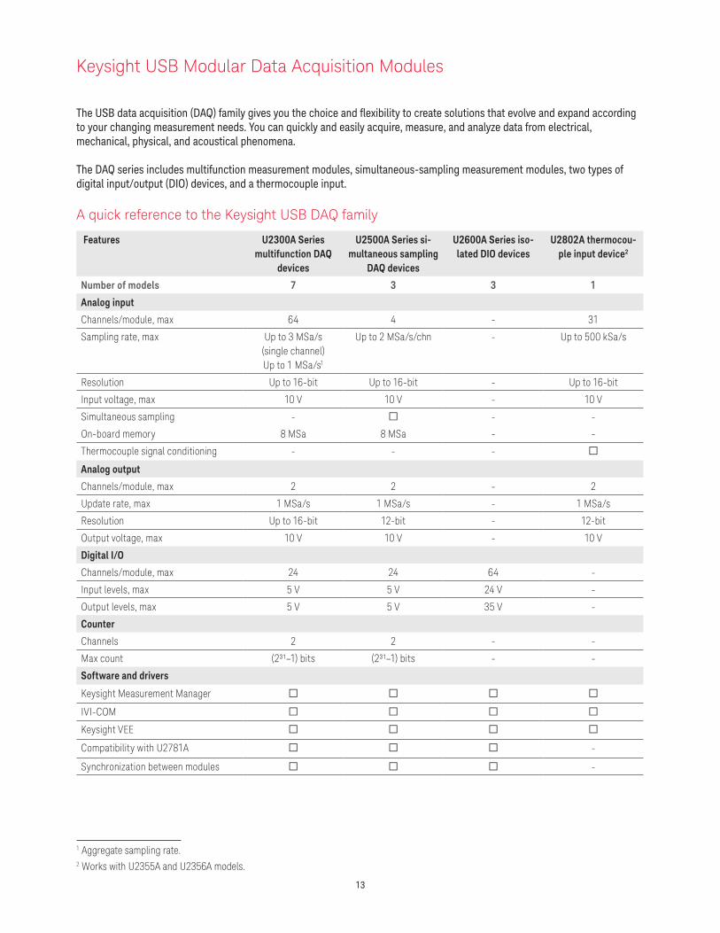
The USB data acquisition (DAQ) family gives you the choice and flexibility to create solutions that evolve and expand according to your changing measurement needs. You can quickly and easily acquire, measure, and analyze data from electrical, mechanical, physical, and acoustical phenomena.
The DAQ series includes multifunction measurement modules, simultaneous-sampling measurement modules, two types of digital input/output (DIO) devices, and a thermocouple input.
A quick reference to the Keysight USB DAQ family
Features U2300A Series multifunction DAQ
devices
U2500A Series si-multaneous sampling
DAQ devices
U2600A Series iso-lated DIO devices
U2802A thermocou-ple input device2
Number of models 7 3 3 1
Analog input
Channels/module, max 64 4 - 31
Sampling rate, max Up to 3 MSa/s(single channel)Up to 1 MSa/s1
Up to 2 MSa/s/chn - Up to 500 kSa/s
Resolution Up to 16-bit Up to 16-bit - Up to 16-bit
Input voltage, max 10 V 10 V - 10 V
Simultaneous sampling - - -
On-board memory 8 MSa 8 MSa - -
Thermocouple signal conditioning - - -
Analog output
Channels/module, max 2 2 - 2
Update rate, max 1 MSa/s 1 MSa/s - 1 MSa/s
Resolution Up to 16-bit 12-bit - 12-bit
Output voltage, max 10 V 10 V - 10 V
Digital I/O
Channels/module, max 24 24 64 -
Input levels, max 5 V 5 V 24 V -
Output levels, max 5 V 5 V 35 V -
Counter
Channels 2 2 - -
Max count (2³¹–1) bits (2³¹–1) bits - -
Software and drivers
Keysight Measurement Manager
IVI-COM
Keysight VEE
Compatibility with U2781A -
Synchronization between modules -
14
Features
– Up to 3 MSa/s sampling rate for a single channel
– Functions as a standalone or modular unit
– Easy to use: Plug-and-play and hot-swappable with Hi-Speed USB 2.0
– Up to 384 channels when incorporated into U2781A Keysight modular product chassis
– Easy-to-use bundled software for quick setup and data logging to PC
– 12-bit or 16-bit analog-to-digital (A/D) resolution
– 24-bit programmable digital input/output
– Self-calibration capability – Compatible with a wide range
of Application Development Environments
– USB 2.0 and USBTMC-USB488 standards
U2300A Series USB Modular Multifunction Data Acquisition Devices
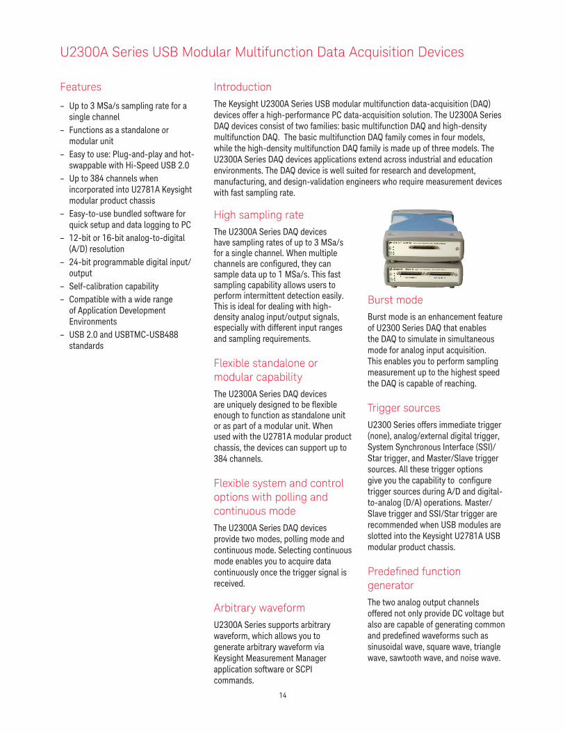
IntroductionThe Keysight U2300A Series USB modular multifunction data-acquisition (DAQ) devices offer a high-performance PC data-acquisition solution. The U2300A Series DAQ devices consist of two families: basic multifunction DAQ and high-density multifunction DAQ. The basic multifunction DAQ family comes in four models, while the high-density multifunction DAQ family is made up of three models. The U2300A Series DAQ devices applications extend across industrial and education environments. The DAQ device is well suited for research and development, manufacturing, and design-validation engineers who require measurement devices with fast sampling rate.
Burst mode Burst mode is an enhancement feature of U2300 Series DAQ that enables the DAQ to simulate in simultaneous mode for analog input acquisition. This enables you to perform sampling measurement up to the highest speed the DAQ is capable of reaching.
Trigger sourcesU2300 Series offers immediate trigger (none), analog/external digital trigger, System Synchronous Interface (SSI)/Star trigger, and Master/Slave trigger sources. All these trigger options give you the capability to configure trigger sources during A/D and digital-to-analog (D/A) operations. Master/Slave trigger and SSI/Star trigger are recommended when USB modules are slotted into the Keysight U2781A USB modular product chassis.
Predefined function generator The two analog output channels offered not only provide DC voltage but also are capable of generating common and predefined waveforms such as sinusoidal wave, square wave, triangle wave, sawtooth wave, and noise wave.
High sampling rateThe U2300A Series DAQ devices have sampling rates of up to 3 MSa/s for a single channel. When multiple channels are configured, they can sample data up to 1 MSa/s. This fast sampling capability allows users to perform intermittent detection easily. This is ideal for dealing with high-density analog input/output signals, especially with different input ranges and sampling requirements.
Flexible standalone or modular capabilityThe U2300A Series DAQ devices are uniquely designed to be flexible enough to function as standalone unit or as part of a modular unit. When used with the U2781A modular product chassis, the devices can support up to 384 channels.
Flexible system and control options with polling and continuous modeThe U2300A Series DAQ devices provide two modes, polling mode and continuous mode. Selecting continuous mode enables you to acquire data continuously once the trigger signal is received.
Arbitrary waveformU2300A Series supports arbitrary waveform, which allows you to generate arbitrary waveform via Keysight Measurement Manager application software or SCPI commands.

15
Product characteristics and general specifications
REMOTE INTERFACE – Hi-Speed USB 2.0* – USBTMC-USB4881
POWER REQUIREMENT – +12 VDC (TYPICAL) – 2 A (MAX) input rated current
POWER CONSUMPTION+12 VDC, 550 mA maximum
OPERATING ENVIRONMENT – Operating temperature from 0 °C to +55 °C – Relative humidity at 15% to 85% RH (non-condensing) – Altitude up to 2000 meters – Pollution Degree 2 – For indoor use only
STORAGE COMPLIANCE–20 °C to 70 °C
SAFETY COMPLIANCECertified with:
– IEC 61010-1:2001/EN 61010-1:2001 (2nd Edition) – USA: UL61010-1: 2004 – Canada: CSA C22.2 No.61010-1:2004
EMC COMPLIANCE – IEC/EN 61326-1 1998 – CISPR 11: 1990/EN55011:1991, Class A, Group 1 – Canada: ICES-001: 1998 – Australia/New Zealand: AS/NZS 2064.1
SHOCK AND VIBRATIONTested to IEC/EN 60068-2
IO CONNECTOR68-pin female VHDCI Type
DIMENSION (W × D × H)Module dimension:
– 120.00 mm × 182.40 mm × 44.00 mm (with plastic casing) – 105.00 mm × 174.54 mm × 25.00 mm (without plastic casing)
Terminal block dimension: – 103.00 mm × 85.20 mm × 42.96 mm
WEIGHT – 565 g (with plastic casing) – 400 g (without plastic casing)
Product outlook and dimensionsFront view
Rear view
Top view
Standard shipped accessories
– AC/DC Power adapter – Power cord – USB extension cable – L-Mount kit (used with modular product
chassis) – Keysight USB Modular Products Quick
Start Guide – Keysight USB Modular Products
Reference CD-ROM – Keysight Automation-Ready CD-ROM
(contains the Keysight IO Libraries Suite) – Certificate of Calibration
Optional accessories
– U2901A Terminal block and SCSI-II 68-pin connector with 1-meter cable
– U2902A Terminal block and SCSI-II 68-pin connector with 2-meter cable
120.00 mm
182.40 mm
44.00 mm
1 Compatible with Microsoft Windows operating systems only.
*If remote connections are necessary, a E5813A USB/LAN hub can be used. Please go to the product’s user guide for more information.

16
Electrical specifications
Basic multifunction USB DAQ
Model number U2351A U2352A U2353A U2354A
Analog input
Resolution 16 bits, no missing codes
Number of channels 16 SE/8 DI (software selectable/channel)
Maximum sampling rate1 250 kSa/s 500 kSa/s
Scan list memory Up to 100 selectable channel entries
Programmable bipolar input range ±10 V, ±5 V, ±2.5 V, ±1.25 V
Programmable unipolar input range 0 to 10 V, 0 to 5 V, 0 to 2.5 V, 0 to 1.25 V
Input coupling DC
Input impedance 1 GΩ / 100 pF
Operational common mode voltage range ±7.5 Vmaximum
Overvoltage protection Power-on: Continuous ±30 V, Power-off: Continuous ±15 V
Trigger sources External analog/digital trigger, SSI/Star trigger2
Trigger modes Pre- trigger, delay-trigger, post-trigger, and middle-trigger
FIFO buffer size Up to 8 MSa
Analog output
Resolution 16 bits - 16 bits -
Number of channels 2 - 2 -
Maximum update rate 1 MSa/s - 1 MSa/s -
Output ranges0 to 10 V, ±10 V,
0 to AO_EXT_REF,±AO_EXT_REF3
- 0 to 10 V, ±10 V,0 to AO_EXT_REF,
±AO_EXT_REF3
-
Output coupling DC - DC -
Output impedance 0.1 Ω typical - 0.1 Ω typical -
StabilityAny passive load
up to 1500 pF- Any passive load
up to 1500 pF-
Power-on state 0 V steady state - 0 V steady state -
Trigger sources
Externalanalog/digital
trigger,SSI/Star trigger2
- Externalanalog/digital
trigger,SSI/Star trigger2
-
Trigger modesPost-trigger and
delay-trigger- Post-trigger and
delay-trigger-
FIFO buffer size
One channel: Maximum 8 MSa
Two channels: Maximum 4 MSa/ch
- One channel: Maximum 8 MSa Two channels:
Maximum 4 MSa/ch
-
Function generation modeSine, square,
triangle, sawtooth, and noise waveforms
- Sine, square, triangle, sawtooth,
and noise waveforms
-

17
Basic multifunction USB DAQ (continued)
Digital I/O
Number of channels 24-bit programmable input/output
Compatibility TTL
Input voltageVIL = 0.7 V max, IIL = 10 μA maxVIH = 2.0 V min, IIH = 10 μA max
Input voltage range –0.5 V to +5.5 V
Output voltageVOL = 0.45 V max, IOL = 8 mA maxVOH = 2.4 V min, IOH = 400 μA max
General purpose digital counter
Maximum count (2³¹–1) bits
Number of channels Two independent up/down counter
Compatibility TTL
Clock source Internal or external
Base clock available 48 MHz
Maximum clock sourcefrequency
12 MHz
Input frequency range4 0.1 Hz to 6 MHz at 50% duty cycle
Pulse width measurement range 0.167 μs to 178.956 s
Analog trigger
Trigger source All analog input channels, External analog trigger (EXTA_TRIG)
Trigger level ±Full scale for internal; ±10 V for external
Trigger conditions Above high, below low, and window (software selectable)
Trigger level resolution 8 bits
Bandwidth 400 kHz
Input impedance for EXTA_TRIG 20 kΩ
Coupling DC
Overvoltage protection Continuous for ± 35 Vmaximum
Digital trigger
Compatibility TTL/CMOS
Response Rising or falling edge
Pulse width 20 ns minimum
Calibration5
On board reference voltage 5 V
Temperature drift ±2 ppm/°C
Stability ±6 ppm/1000 hrs
General
Remote interface Hi-Speed USB 2.0
Device class USBTMC-USB488
Programmable interface Standard Commands for Programmable Instruments (SCPI) and IVI-COM
1 When multiple channels are used, the sampling rate of each channel is the maximum sampling rate divided by the number of channels used.2 System Synchronous Interface (SSI) and Star trigger commands are used when modular devices are used in the product chassis.3 Maximum external reference voltage for analog output channels (AO_EXT_REF) is ±10 V.4 Measurement frequency’s resolution:
= 12 MHz/n, n = 2, 3, 4, 5, ..., 120 M
= 6 MHz, 4 MHz, 3 MHz, 2.4 MHz, 2.0 MHz, ..., 0.1 Hz (up to six decimal points)5 20 minutes warm-up time is recommended.

18
High density multifunction USB DAQ
Model number U2355A U2356A U2331A
Analog input
Resolution 16 bits, no missing codes 12 bits, no missing codes
Number of channels 64 SE/32 DI (software selectable/channel)
Maximum sampling rate1 250 kSa/s 500 kSa/s3 MSa/s (single channel)
1 MSa/s (multiple channels)
Scan list memory Up to 100 selectable channel entries
Programmable bipolar input range ±10 V, ±5 V, ±2.5 V, ±1.25 V±10 V, ±5 V, ±2.5 V,
±1.25 V, ±1 V, ±0.5 V,±0.25 V, ±0.2 V, ±0.05 V
Programmable unipolar input range 0 to 10 V, 0 to 5 V, 0 to 2.5 V, 0 to 1.25 V
0 to 10 V, 0 to 5 V, 0 to 4 V,0 to 2.5 V, 0 to 2 V, 0 to 1 V,0 to 0.5 V, 0 to 0.4 V, 0 to
0.1V
Input coupling DC
Input impedance 1 GΩ / 100 pF
Operational common mode voltage range ±7.5 V maximum
Overvoltage protection Power-on: Continuous ±30 V, Power-off: Continuous ±15 V
Trigger sources External analog/digital trigger, SSI/Star trigger2
Trigger modes Pre- trigger, delay-trigger, post-trigger, and middle-trigger
FIFO buffer size Up to 8 MSa
Analog output
Resolution 12 bits
Number of channels 2
Maximum update rate 1 MSa/s
Output ranges 0 to 10 V, ±10 V, 0 to AO_EXT_REF, ±AO_EXT_REF3
Output coupling DC
Output impedance 0.1 Ω Typical
Stability Any passive load up to 1500 pF
Power-on state 0 V steady state
Trigger sources External analog/digital trigger, SSI/Star trigger2
Trigger modes Post-trigger and delay-trigger
FIFO buffer sizeOne channel: Maximum 8 MSa
Two channels: Maximum 4 MSa/ch
Function generation mode Sine, square, triangle, sawtooth, and noise waveforms
Digital I/O
Number of bits 24-bit programmable input/output
Compatibility TTL
Input voltageVIL = 0.7 V max, IIL = 10 μA maxVIH = 2.0 V min, IIH = 10 μA max
Input voltage range –0.5 V to +5.5 V
Output voltageVOL = 0.45 V max, IOL = 8 mA maxVOH = 2.4 V min, IOH = 400 μA max

19
High density multifunction USB DAQ (continued)
General purpose digital counter
Maximum count (2³¹ – 1) bits
Number of channels Two independent up/down counter
Compatibility TTL
Clock source Internal or external
Base clock available 48 MHz
Maximum clock source frequency 12 MHz
Input frequency range4 0.1 Hz to 6 MHz at 50% duty cycle
Pulse width measurement range 0.167 μs to 178.956 s
Analog trigger
Trigger source All analog input channels, External analog trigger (EXTA_TRIG)
Trigger level ±Full scale for internal; ±10 V for external
Trigger conditions Above high, below low, and window (software selectable)
Trigger level resolution 8 bits
Bandwidth 400 kHz
Input impedance for EXTA_TRIG 20 kΩ
Coupling DC
Overvoltage protection Continuous for ±35 Vmaximum
Digital trigger
Compatibility TTL/CMOS
Response Rising or falling edge
Pulse width 20 ns minimum
Calibration5
On board reference 5 V
Temperature drift ±2 ppm/°C
Stability ±6 ppm/1000 hrs
General
Remote interface Hi-Speed USB 2.0
Device class USBTMC-USB488
Programmable interface Standard Commands for Programmable Instruments (SCPI) and IVI-COM
1 When multiple channels are used in the U2355A or U2356A, the sampling rate of each channel is the maximum sampling rate divided by the number of channels used. For multiple channels used in the U2331A, the sampling rate of each channel = (1 MSa/s) / number of channels used.
2 System Synchronous Interface (SSI) and Star trigger commands are used when modular devices are used in the product chassis.3 Maximum external reference voltage for analog output channels (AO_EXT_REF) is ±10 V.4 Measurement frequency’s resolution:
= 12 MHz/n, n = 2, 3, 4, 5, ..., 120 M
= 6 MHz, 4 MHz, 3 MHz, 2.4 MHz, 2.0 MHz, ..., 0.1 Hz (up to six decimal points)5 20 minutes warm-up time is recommended.

20
Electrical measurement specifications
Basic multifunction USB DAQ
Model number U2351A, U2352A U2353A, U2354A
Analog input measurement1
Function 23 °C ± 5 °C 0 °C to 18 °C 28 °C to 45 °C
23 °C ± 5 °C 0 °C to 18 °C 28 °C to 45 °C
Offset error ±1 mV ±5 mV ±1 mV ±5 mV
Gain error ±2 mV ±5 mV ±2 mV ±5 mV
–3 dB Small signal bandwidth2 760 kHz 1.5 MHz
1% THD Large signal bandwidth2 300 kHz 300 kHz
System noise 1 mVrms 2 mVrms 1 mVrms 2.5 mVrms
CMRR 62 dB 62 dB
Spurious-Free Dynamic Range (SFDR)3 88 dB 82 dB
Signal-to-Noise and Distortion Ratio (SINAD)3
80 dB 78 dB
Total Harmonic Distortion (THD)3 –90 dB –82 dB
Signal-to-Noise Ratio (SNR)3 80 dB 78 dB
Effective Number of Bits (ENOB)3 13 12.6
Model number U2351A, U2353A
Analog output measurement1
Function 23 °C ± 5 °C 0 °C to 18 °C 28 °C to 45 °C
Offset error ±1 mV ±4 mV
Gain error ±4mV ±5 mV
Slew rate 19 V/μs
Rise time 0.9 μs
Fall time 0.9 μs
Settling time to 1% output error 4 μs
Driving capability 5 mA
Glitch energy 5 ns-V (Typical), 80 ns-V (Maximum)
1 Specifications are for 20 minutes of warm-up time, calibration temperature at 23 °C and input range of ±10 V.2 Specifications are based on the following test condition:
Bandwidth test Model number Test conditions (DUT setting at ±10 V bipolar)
–3 dB Small signal bandwidth1% THD large signal bandwidth
U2351AU2352A
Sampling rate:Input voltage:
– –3 dB Small signal bandwidth – 1% THD Large signal bandwidth
250 kSa/s
– 10% FSR – FSR –1 dB FS
U2353AU2354A
Sampling rate:Input voltage:
– –3 dB Small signal bandwidth – 1% THD Large signal bandwidth
500 kSa/s
– 10% FSR – FSR –1 dB FS
3 Specifications are based on the following test conditions:
Dynamic range test Model number Test conditions (DUT setting at ±10 V bipolar)
SFDR, THD, SINAD, SNR, ENOB U2351AU2352A
– Sampling rate: – Fundamental frequency: – Number of points: – Fundamental input voltage:
250 kSa/s2.4109 kHz8192FSR –1 dB FS
U2353AU2354A
– Sampling rate: – Fundamental frequency: – Number of points: – Fundamental input voltage:
500 kSa/s4.974 kHz16384FSR –1 dB FS

21
High density multifunction USB DAQ
Model number U2355A U2356A U2331A
Analog input measurement1
Function 23 °C ± 5 °C 0 °C to 18 °C 28 °C to 45
°C
23 °C ± 5 °C 0 °C to 18 °C 28 °C to 45
°C
23 °C ± 5 °C 0 °C to 18 °C 28 °C to 45
°C
Offset error ±1 mV ±2 mV ±1 mV ±2 mV ±2 mV ±3 mV
Gain error ±2 mV ±3 mV ±2 mV ±6 mV ±6 mV ±7.5 mV
–3 dB small signal bandwidth2 760 kHz 1.3 MHz 1.2 MHz
1% THD large signal bandwidth2 400 kHz 400 kHz N/A
System noise 1 mVrms 2 mVrms 1 mVrms 4 mVrms 3 mVrms 5 mVrms
CMRR 64 dB 61 dB 62 dB
Spurious-Free Dynamic Range (SFDR)3 88 dB 86 dB 71 dB
Signal-to-Noise and Distortion Ratio (SINAD)3
80 dB 78 dB 72 dB
Total Harmonic Distortion (THD)3 –90 dB –84 dB –76 dB
Signal-to-Noise Ratio (SNR)3 80 dB 78 dB 72 dB
Effective Number of Bits (ENOB)3 13 12.6 11.6
1 Specifications are for 20 minutes of warm-up time, calibration temperature at 23 °C and input range of ±10 V.2 Specifications are based on the following test conditions.
Bandwidth test Model number Test conditions (DUT setting at ±10 V bipolar)
–3 dB Small signal bandwidth1% THD Large signal bandwidth
U2355A Sampling rate:Input voltage:
– –3 dB Small signal bandwidth – 1% THD Large signal bandwidth
250 kSa/s
10% FSRFSR –1 dB FS
U2356A Sampling rate:Input voltage:
– –3 dB Small signal bandwidth – 1% THD Large signal bandwidth
500 kSa/s
10% FSRFSR –1 dB FS
U2331A Sampling rate:Input voltage:
– –3 dB Small signal bandwidth – 1% THD Large signal bandwidth
3 MSa/s
10% FSRFSR –1 dB FS
3 Specifications are based on the following test conditions.
Dynamic range test Model number Test conditions (DUT setting at ±10 V bipolar)
–3 dB Small signal bandwidth1% THD Large signal bandwidth
U2355A – Sampling rate: – Fundamental frequency: – Number of points: – Fundamental input voltage:
250 kSa/s2.4109 kHz8192FSR –1 dB FS
U2356A – Sampling rate: – Fundamental frequency: – Number of points: – Fundamental input voltage:
500 kSa/s4.974 kHz16384FSR –1 dB FS
U2331A – Sampling rate: – Fundamental frequency: – Number of points: – Fundamental input voltage:
3 MSa/s29.892 kHz65536FSR –1 dB FS

22
High density multifunction USB DAQ (continued)
Model number U2355A, U2356A U2331A
Analog output measurement1
Function 23 °C ± 5 °C0 °C to 18 °C
28 °C to 45 °C23 °C ± 5 °C
0 °C to 18 °C 28 °C to 45 °C
Offset error ±1 mV ±4 mV ±1.5 mV ±3 mV
Gain error ±4 mV ±5 mV ±4 mV ±5 mV
Slew rate 19 V/μs 19 V/μs
Rise time 0.9 μs 0.9 μs
Fall time 0.9 μs 0.9 μs
Settling time to 1% output error 4 μs 4 μs
Driving capability 5 mA 5 mA
Glitch energy 5 ns-V (Typical), 80 ns-V (Maximum) 5 ns-V (Typical), 80 ns-V (Maximum)
1 Specifications are for 20 minutes of warm-up time, calibration temperature at 23 °C and input range of ±10 V.

23
DC Characteristics
Accuracy Specifications
Model Number U2351A, U2352A, U2353A, U2354A
Analog Input
Unipolar Range (V) Offset Error (mV)1 Gain Error (mV) Accuracy (% of reading + offset error)2
10 1.5 2.0 0.04% + 1.5 mV
5 1.5 2.0 0.08% + 1.5 mV
2.5 1.0 1.0 0.08% + 1.0 mV
1.25 1.0 1.0 0.16% + 1.0 mV
Bipolar Range (V) Offset Error (mV)1 Gain Error (mV) Accuracy (% of reading + offset error)2
10 1.0 2.0 0.02% + 1.0 mV
5 1.0 2.0 0.04% + 1.0 mV
2.5 1.0 1.5 0.06% + 1.0 mV
1.25 1.0 1.5 0.12% + 1.0 mV
Model Number U2355A, U2356A
Unipolar Range (V) Offset Error (mV)1 Gain Error (mV) Accuracy (% of reading + offset error)2
10 1.0 1.5 0.03% + 1.0 mV
5 1.0 1.5 0.06% + 1.0 mV
2.5 1.0 1.0 0.08% + 1.0 mV
1.25 1.0 1.0 0.16% + 1.0 mV
Bipolar Range (V) Offset Error (mV)1 Gain Error (mV) Accuracy (% of reading + offset error)2
10 1.0 2.0 0.02% + 1.0 mV
5 1.0 2.0 0.04% + 1.0 mV
2.5 1.0 1.5 0.06% + 1.0 mV
1.25 1.0 1.5 0.12% + 1.0 mV
Model U2331A
Unipolar Range (V) Offset Error (mV)1 Gain Error (mV) Accuracy (% of reading + offset error)2
10 1.5 4.0 0.08% + 1.5 mV
5 1.5 2.0 0.08% + 1.5 mV
4 1.5 2.0 0.10% + 1.5 mV
2.5 1.0 1.5 0.12% + 1.0 mV
2 1.0 1.0 0.10% + 1.0 mV
1 1.0 1.0 0.20% + 1.0 mV
0.5 1.0 1.0 0.41% + 1.0 mV
0.4 1.0 1.0 0.51% + 1.0 mV
0.1 1.0 1.0 2.04% + 1.0 mV
– The above specifications are typical for 23 °C. – Specifications are for 20 minutes warm-up and self calibration. – The measurement are calculated with 100 points avearaging of data.
1 Offset error is measured at midscale of full range.2 Accuracy = ± [% of |(Gain error / (Measured value – Midscale of FSR))| + Offset error]

24
Accuracy Specifications (Continued)
Model U2331A
Bipolar Range (V) Offset Error (mV)1 Gain Error (mV) Accuracy (% of reading + offset error)2
10 2.0 6.0 0.06% + 2.0 mV
5 1.5 4.0 0.08% + 1.5 mV
2.5 1.5 2.0 0.08% + 1.5 mV
1.25 1.0 1.5 0.12% + 1.0 mV
1 1.0 1.0 0.10% + 1.0 mV
0.5 1.0 1.0 0.20% + 1.0 mV
0.25 1.0 1.0 0.40% + 1.0 mV
0.2 1.0 1.0 0.50% + 1.0 mV
0.05 1.0 1.0 2.02% + 1.0 mV
– The above specifications are typical for 23 °C. – Specifications are for 20 minutes warm-up and self calibration. – The measurement are calculated with 100 points averaging of data.
Model U2351A, U2352A, U2353A, U2354A
Analog output
Unipolar Range (V) Offset Error (mV)3 Gain Error (mV) Accuracy (% of reading + offset error)4
10 1.0 2.0 0.02% + 1.0 mV
Bipolar Range (V) Offset Error (mV)3 Gain Error (mV) Accuracy (% of reading + offset error)4
10 1.0 4.0 0.04% + 1.0 mV
Model U2355A, U2356A
Unipolar Range (V) Offset Error (mV)3 Gain Error (mV) Accuracy (% of reading + offset error)4
10 1.0 2.0 0.02% + 1.0 mV
Bipolar Range (V) Offset Error (mV)3 Gain Error (mV) Accuracy (% of reading + offset error)4
10 1.0 4.0 0.04% + 1.0 mV
Model U2331A
Unipolar Range (V) Offset Error (mV)3 Gain Error (mV) Accuracy (% of reading + offset error)4
10 2.5 4.0 0.04% + 2.5 mV
Bipolar Range (V) Offset Error (mV)3 Gain Error (mV) Accuracy (% of reading + offset error)4
10 1.5 4.0 0.04% + 1.5 mV
– The above specifications are typical for 23 °C. – Specifications are for 20 minutes warm-up and self calibration.
1 Offset error is measured at midscale of full range.2 Accuracy = ± [% of |(Gain error / (Measured value – Midscale of FSR))| + Offset error]3 Offset error is measured at 0 V.4 Accuracy = ± [% of |Gain error/Output value| + Offset voltage]

25
Various features of the U2500A Series
– Quick and easy USB setup – High sampling rate of up to 2
MSa/s for each channel – Dedicated analog-to-digital
(ADC) that allows simultaneous sampling of data
– Flexible standalone or modular capability that enables lower startup cost
– SCPI and IVI-COM supported with a wide range of ADE compatibility that minimizes work time and increases software choices
– Easy-to-use application software and command logger function for easy SCPI command conversion into snippets of VEE, VB, C++, and C# code
Features
– Simultaneous sampling with up to 2 MSa/s sampling rate for each channel
– Multifunction DAQ solution — AI, AO, DIO, counter
– Dedicated ADC per channel – 14-bit or 16-bit resolution – 24-bit programmable digital input/
output – Functions as a standalone or
modular unit – Supports SCPI and IVI-COM – Compatible with a wide range of
ADEs – Easy-to-use bundled software – Command logger function – USB 2.0 and USBTMC-USB488
standards
High sampling rate of up to 2 MSa/sThe U2500A Series provides a high analog input sampling rate coverage of up to 2 MSa/s for each channel. The high sampling rate coverage offered is ideal for transient signal applications such as sonar analysis.
Simultaneous sampling of dataThe U2500A Series has dedicated ADCs that enable simultaneous signals acquisition, which makes the U2500A Series suitable for your phase-sensitive applications.
U2500A Series USB Modular Simultaneous Sampling Multifunction DAQ Devices
IntroductionThe Keysight U2500A Series USB simultaneous sampling multifunction data acquisition (DAQ) devices are high-performance modules that consist of three models — the U2531A, U2541A, and U2542A. The U2500A Series provides up to four channels with resolutions of 14-bit and 16-bit. The U2531A can sample up to 2 MSa/s for each channel with a resolution of 14 bits, while the U2541A and U2542A can sample up to 250 kSa/s and 500 kSa/s for each channel respectively with a resolution of 16 bits.

26
Product characteristics and General Specifications
REMOTE INTERFACE – Hi-Speed USB 2.0* – USBTMC-USB4881
POWER REQUIREMENT – +12 VDC (TYPICAL) – 2 A (MAX) input rated current – Installation Category II
POWER CONSUMPTION+12 VDC, 480 mA maximum
OPERATING ENVIRONMENT – Operating temperature from 0 °C to +55 °C – Relative humidity at 15% to 85% RH (non-condensing) – Altitude up to 2000 meters – Pollution Degree 2 – For indoor use only
STORAGE COMPLIANCE–20 °C to 70 °C
SAFETY COMPLIANCECertified with:
– IEC 61010-1:2001/EN 61010-1:2001 (2nd Edition) – USA: ANSI/UL 61010-1:2004 – Canada: CSA C22.2 No.61010-1:2004
EMC COMPLIANCE – IEC 61326-1:2002/EN 61326-1:1997+A2:2001+A3:2003 – CISPR 11: 1990/EN 55011:1990-Group 1 Class A – Canada: ICES-001:2004 – Australia/New Zealand: AS/NZS CISPR 11:2004
SHOCK AND VIBRATIONTested to IEC/EN 60068-2
IO CONNECTOR68-pin female VHDCI Type
DIMENSION (W × D × H)Module dimension:
– 120.00 mm × 182.40 mm × 44.00 mm (with plastic casing) – 105.00 mm × 174.54 mm × 25.00 mm (without plastic casing)
Terminal block dimension: – 103.00 mm × 85.20 mm × 42.96 mm
WEIGHT – 565 g (with plastic casing) – 400 g (without plastic casing)
Product outlook and dimensionsFront view
Rear view
Top view
Standard shipped accessories
– AC/DC Power adapter – Power cord – USB extension cable – L-Mount kit (used with modular product
chassis) – Keysight USB Modular Products Quick
Start Guide – Keysight Measurement Manager for
U2500A Series Quick Start Guide – Keysight USB Modular Products
Reference CD-ROM – Keysight Automation-Ready CD-ROM
(contains the Keysight IO Libraries Suite) – Certificate of Calibration
Optional accessories
– U2901A Terminal block and SCSI-II 68-pin connector with 1-meter cable
– U2902A Terminal block and SCSI-II 68-pin connector with 2-meter cable
120.00 mm
182.40 mm
44.00 mm
1 Compatible with Microsoft Windows operating systems only.
*If remote connections are necessary, a E5813A USB/LAN hub can be used. Please go to the product’s user guide for more information.

27
Product specifications
Model number U2531A U2541A U2542A
Analog input
Resolution 14 bits 16 bits
Number of channels 4 differential input channels (software selectable/channel)
Maximum sampling rate 2 MSa/s 250 kSa/s 500 kSa/s
Programmable bipolar input range1 ±10 V, ±5 V, ±2.5 V, ±1.25 V
Programmable unipolar input range 0 to 10 V, 0 to 5 V, 0 to 2.5 V, 0 to 1.25 V
Input coupling DC
Input impedance 1 GΩ/100 pF
Operational common mode voltage range ±8.0 V maximum
Overvoltage range Power-on: Continuous ±30 V, Power-off: Continuous ±15 V
Trigger sources External analog/digital trigger, SSI/star trigger2
Trigger modes Pre-trigger, delay-trigger, post-trigger, and middle-trigger
FIFO buffer size Up to 8 MSa
Analog output
Resolution 12 Bits
Number of channels 2
Maximum update rate 1 MSa/s
Output ranges 0 to 10 V, ±10 V, 0 to AO_EXT_REF, ±AO_EXT_REF3
Output coupling DC
Output impedance 0.1 Ω Typical
Stability Any passive load up to 1500 pF
Power-on state 0 V steady state
Trigger sources External analog/digital trigger, SSI/star trigger2
Trigger modes Delay trigger, post trigger
FIFO buffer size1 Channel used: Maximum 8 MSa
4 Channels used: Maximum 2 MSa/ch
Glitch energy 5 ns-V (Typical), 80 ns-V (Maximum)
Driving capability 5 mA
Function generation mode Sine, square, triangle, sawtooth, and noise waveforms
Digital input/output
Number of bits 24-bit programmable input/output
Compatibility TTL
Input voltageVIL = 0.7 V maximum; IIL = 10 μA maximum VIH = 2.0 V minimum; IIH = 10 μA maximum
Input voltage range –0.5 V to +5.5 V
Output voltageVOL = 0.45 V maximum; IOL = 8 mA maximum
VOH = 2.4 V minimum; IOH = 400 μA maximum
General purpose digital timer/counter
Maximum count (231 – 1) bits
Number of channels 2 Independent up/down counter
Compatibility TTL
Clock source Internal or external
Base clock available 48 MHz
Maximum clock source frequency 12 MHz
Input frequency range4 0.1 Hz to 6 MHz at 50% duty cycle
Pulse width measurement range 0.167 μs to 178.956 s ±0.0833 μs

28
Product specifications (continued)
Model number U2531A U2541A U2542A
Analog trigger
Trigger source All analog input channels, External analog trigger (EXTA_TRIG)
Trigger level±Full scale for internal
±10 V for external
Trigger conditions Above high, below low, and window (software selectable)
Trigger level resolution 8 bits
Bandwidth 400 kHz
Input impedance for EXTA_TRIG 20 kΩ
Coupling DC
Overvoltage protection Continuous for ±35 V maximum
Digital trigger
Compatibility TTL/CMOS
Response Rising or falling edge
Pulse width 20 ns minimum
Calibration5
On board reference voltage 5 V
Temperature drift ±2 ppm/°C
Stability ±6 ppm/1000 hours
Power consumption
Input voltage (DC) +12 VDC
Input current 480 mA maximum 390 mA maximum
Physical attributes
Dimensions (W × D × H)120.00 mm × 182.40 mm × 44 mm (with plastic casing)
105.00 mm × 174.54 mm × 25.00 mm (without plastic casing)
IO connector 68-pin female VHDCI type
Weight 565 g with plastic casing400 g without plastic casing
Environmental condition
Operating temperature 0 to 55 °C
Storage temperature –20 °C to 70 °C
Relative humidity 15% to 85% RH (non-condensing)
General
Remote interface Hi-Speed USB 2.0
Device class USBTMC-USB488
Programmable interface SCPI and IVI-COM
1 Maximum input voltage for analog input is ±10 V.2 System Synchronous Interface (SSI) and star trigger commands are applicable when modular devices are used in modular product chassis
(U2781A).3 Maximum external reference voltage for analog output (AO_EXT_REF) is ±10 V.4 Measurement frequency’s resolution:
= 12 MHz/n, n = 2, 3, 4, 5, ..., 120 M
= 6 MHz, 4 MHz, 3 MHz, 2.4 MHz, 2.0 MHz, ..., 0.1 Hz (up to six decimal points)5 Recommended for 20 minutes warm-up time.

29
Electrical specifications and characteristics
Analog input characteristics1
Model number U2531A U2541A U2542A
23 °C ± 5 °C 0 °C to 18 °C 28 °C to 55 °C
23 °C ± 5 °C 0 °C to 18 °C 28 °C to 55 °C
23 °C ± 5 °C 0 °C to 18 °C 28 °C to 55 °C
Offset error2 ±2 mV ±2 mV ±1 mV ±1 mV ±1 mV ±1 mV
Gain error2 ±6 mV ±6 mV ±2 mV ±2.5 mV ±2 mV ±2.5 mV
–3 dB Small signal bandwidth 1.2 MHz 600 KHz 1.0 MHz
1% THD Large signal bandwidth 400 KHz 400 KHz 400 KHz
System noise3 2.0 mVrms 0.5 mVrms 0.5 mVrms
CMRR (DC to 60 Hz) 64 dB 80 dB 80 dB
Spurious-Free Dynamic Range (SFDR) 76 dB 88 dB 86 dB
Signal-to-Noise and Distortion Ratio (SINAD)
70 dB 82 dB 80 dB
Total Harmonic Distortion (THD) –72 dB –86 dB –84 dB
Signal-to-Noise Ratio (SNR) 72 dB 84 dB 82 dB
Effective Number of Bits (ENOB) 11.3-bit 13.3-bit 13.0-bit
Channels crosstalk4 66 dB 84 dB 80 dB
Analog output characteristics1
Model number U2531A U2541A U2542A
23 °C ± 5 °C 0 °C to 18 °C 28 °C to 55 °C
23 °C ± 5 °C 0 °C to 18 °C 28 °C to 55 °C
23 °C ± 5 °C 0 °C to 18 °C 28 °C to 55 °C
Offset error ±1 mV ±3 mV ±1 mV ±3 mV ±1 mV ±3 mV
Gain error ±3 mV ±4 mV ±2 mV ±4 mV ±2 mV ±4 mV
Slew rate 15 V/μs 15 V/μs 15 V/μs
Rise time 1.1 μs 1.2 μs 1.1 μs 1.2 μs 1.1 μs 1.2 μs
Fall time 1.1 μs 1.2 μs 1.1 μs 1.2 μs 1.1 μs 1.2 μs
Settling time(s) to 1% output error 2 μs 2 μs 2 μs
1 Specifications are based on 20 minutes warm-up, self-calibration temperature at 23 °C, and bipolar input range of ±10 V. 2 The measurements are calculated with 100 points averaging of data.3 The noise rms value is the standard deviation of 20000 points.4 The crosstalk measurements are tested up to input frequency of Fin = MaxSamplingRate/2.

30
Test condition
Dynamic range test for U2500A Series DAQ devices
Dynamic range test Model Test conditions (DUT setting at ±10 V bipolar)
SFDR, THD, SINAD, SNR, ENOB
U2531A – Sampling rate: – Fundamental frequency: – Number of points: – Fundamental input voltage:
2 MSa/s19.927 kHz65536FSR –1 dB FS
U2541A – Sampling rate: – Fundamental frequency: – Number of points: – Fundamental input voltage:
250 kSa/s2.4109 kHz8192FSR – 1 dBFS
U2542A – Sampling rate: – Fundamental frequency: – Number of points: – Fundamental input voltage:
500 kSa/s4.974 kHz16384FSR – 1 dBFS
Bandwidth test for U2500A Series DAQ devices
Bandwidth test Model Test conditions (DUT setting at ±10 V bipolar)
–3 dB Small signal bandwidth:1% THD Large signal bandwidth:
U2531A – Sampling rate: – Input voltage – –3 dB Small signal bandwidth: – 1% THD Large signal bandwidth:
2 MSa/s
10% FSRFSR – 1 dBFS
U2541A – Sampling rate: – Input voltage – –3 dB Small signal bandwidth: – 1% THD Large signal bandwidth:
250 kSa/s
10% FSRFSR – 1 dBFS
U2542A – Sampling rate: – Input voltage – –3 dB Small signal bandwidth: – 1% THD Large signal bandwidth:
500 kSa/s
10% FSRFSR – 1 dBFS

31
Typical performance graph

32
DC characteristics
Accuracy specifications1
Model U2541A, U2542A
Analog input
Unipolar range (V) Offset error (mV)2 Gain error (mV) Accuracy (% of reading + offset error)3
10 1.0 1.0 0.02% + 1.0 mV
5 1.0 1.0 0.04% + 1.0 mV
2.5 1.0 1.0 0.08% + 1.0 mV
1.25 1.0 1.0 0.16% + 1.0 mV
Bipolar range (V)
10 1.0 2.0 0.02% + 1.0 mV
5 1.0 1.0 0.02% + 1.0 mV
2.5 1.0 1.0 0.04% + 1.0 mV
1.25 1.0 1.0 0.08% + 1.0 mV
Model U2531A
Unipolar range (V) Offset error (mV)2 Gain error (mV) Accuracy (% of reading + offset error)3
10 2.0 3.0 0.06% + 2.0 mV
5 1.5 1.5 0.06% + 1.5 mV
2.5 1.0 1.0 0.08% + 1.0 mV
1.25 1.0 1.0 0.16% + 1.0 mV
Bipolar range (V)
10 2.0 6.0 0.06% + 2.0 mV
5 1.5 3.0 0.06% + 1.5 mV
2.5 1.0 2.0 0.08% + 1.0 mV
1.25 1.0 1.0 0.08% + 1.0 mV
Model U2541A, U2542A
Analog output
Unipolar range (V) Offset error (mV)2 Gain error (mV) Accuracy (% of reading + offset error)4
10 1.0 2.0 0.02% + 1.0 mV
Bipolar range (V)
10 1.0 2.0 0.02% + 1.0 mV
Model U2531A
Unipolar range (V) Offset error (mV)2 Gain error (mV) Accuracy (% of reading + offset error)4
10 1.0 3.0 0.03% + 1.0 mV
Bipolar range (V)
10 1.0 3.0 0.03% + 1.0 mV
1 Specifications are based on 20 minutes warm-up, and self-calibration temperature at 23 °C.2 Offset error is measured at 0 V.3 Accuracy = ± [% of Gain error/(Measured value – Midscale) + Offset error]4 Accuracy = ± (% of Gain error/Output value + Offset error)

33
Various features to meet industrial demands
– Quick and easy USB setup – High channel count to drive
more actuators and control more sensors by using just one DIO device
– Opto-isolation for more reliable and improved signal quality
– High isolated transient voltage protection of the digital IO lines is able to protect your system from being damaged
– Wide input voltage range of 10 V to 24 V to sense the status of external sensors
– High output voltage range of 5 V to 35 V provides the capability to drive a wide array of actuators in industrial automation applications
– On-board isolated +5 V power supply enables simple application and function tests without the need for an external source
– SCPI and IVI-COM supports and compatibility with a wide range of ADEs minimize work time and provides a higher flexibility of software choices
– Command logger function provided in the bundled software allows easy command conversion into snippets of VEE, VB, C++, and C# code
– Interrupt function for automatic triggering of your system when a digital change of state occurs
– Virtual Port grouping function allows grouping of any eight input/output bits into one virtual port for simultaneous operations
IntroductionThe Keysight U2600A Series USB isolated digital I/O devices are high-performance modules that consist of three models— the U2651A isolated 32-bit DI and 32-bit DO, U2652A isolated 64-bit DI, and U2653A isolated 64-bit DO. The U2600A Series provides up to eight channels with 64-bit of high-density opto-isolated digital input and digital output for USB 2.0 interface-based industrial applications, such as driving relays, actuators, or valve. The U2600A Series targets a wide range of applications both in industrial automation and education.
Features
– Hi-Speed USB 2.0 (480 Mbps) Functions as standalone or modular unit
– Up to 64 opto-isolated digital I/O lines with maximum transient voltage of 1250 Vpeak protection
– Supports input voltage ranging from 10 V to 24 V
– External supply voltage ranging from 5 V to 35 V for external load
– Compatible with a wide range of ADEs
– Supports SCPI and IVI-COM – Easy-to-use bundled software – Command logger function – USB 2.0 and USBTMC-USB488
standards – Interrupt function – Virtual Port grouping function
U2600A Series USB Modular Isolated Digital I/O Devices

34
High channel count with opto-isolated digital input and digital outputThe U2600A Series has high channel count with up to 64-bit high-density opto-isolated digital input and digital output that increases its usability. With just one DIO device, you are able to drive more actuators and control more sensors. Furthermore, opto-isolation separates the electrical connection between circuits for better PC system protection. Thus, making the U2600A Series more reliable with its opto-isolated digital input and digital output.
High isolated transient voltage protectionIsolation prevents any potential harmful current that may be induced by transient voltage spikes from flowing through the digital IO lines to the system. The robust 1250 Vpeak transient isolation protection allows the U2600A Series to have direct connection to a wide range of industrial sensors and actuators, making the U2600A suitable for most industrial applications.
High I/O voltage rangeThe U2600A Series has a high input/output voltage range that is suitable for demanding industrial applications such as driving relays and actuators, which require up to 24 V. The U2600A Series has a wide input range of 10 V to 24 V to sense the status of external sensors. It also has an external supply voltage that is ranging from 5 V to 35 V, which enables the U2600A Series to drive a wide range of actuators.
Interrupt functionThe U2600A Series has an interrupt function that automatically triggers your system when a digital change of state occurs. Unlike polling, this function minimizes the overheads of your PC system especially when the U2600A Series is used in multitasking applications.
Virtual Port grouping functionThe Virtual Port grouping function allows users to randomly select any eight input or output bits and group them into one channel as a virtual DIO port.
The following describes the key advantages of using the Virtual Port grouping function:
– You can control multiple bits simultaneously for the instantaneous control of multiple machines, such as emergency stop control.
– You can make changes to your port assignments whenever required as the Virtual Port is easily programmable.
– It eliminates the need for you to rewire your hardware devices to different bits for different applications. This makes the U2600A Series suitable for research and development applications, which require on-going testing that involves many hardware setup changes.

35
Product characteristics and general specifications
REMOTE INTERFACE – Hi-Speed USB 2.0* – USBTMC-USB4881
POWER REQUIREMENT – +12 VDC (TYPICAL) – 2 A (MAX) input rated current – Installation Category II
POWER CONSUMPTION+12 VDC, 260 mA maximum
OPERATING ENVIRONMENT – Operating temperature from 0 °C to +55 °C – Relative humidity at 15% to 85% at 40 °C (non-condensing) – Altitude up to 2000 meters – Pollution Degree 2 – For indoor use only
STORAGE COMPLIANCE–20 °C to 70 °C
SAFETY COMPLIANCECertified with:
– IEC 61010-1:2001/EN 61010-1:2001 (2nd Edition) – USA: ANSI/UL 61010-1:2004 – Canada: CSA C22.2 No.61010-1:2004
EMC COMPLIANCE – IEC 61326-1:2002/EN 61326-1:1997+A2:2001+A3:2003 – CISPR 11: 1990/EN 55011:1990-Group 1 Class A – Canada: ICES-001:2004 – Australia/New Zealand: AS/NZS CISPR 11:2004
SHOCK AND VIBRATIONTested to IEC/EN 60068-2
IO CONNECTOR100-pin SCSI-II connector
DIMENSION (W × D × H)Module dimension:
– 120.00 mm × 182.40 mm × 44.00 mm (with plastic casing) – 105.00 mm × 174.54 mm × 25.00 mm (without plastic casing)
Terminal block dimension: – 158.00 mm × 118.60 mm × 51.50 mm
WEIGHT – 565 g (with plastic casing) – 370 g (without plastic casing)
Product outlook and dimensionsFront view
Rear view
Top view
Standard shipped accessories
– AC/DC Power adapter – Power cord – USB extension cable – L-Mount kit (used with modular product
chassis) – Keysight USB Modular Products Quick
Start Guide – Keysight Measurement Manager for
U2600A Series Quick Start Guide – Keysight USB Modular Products
Reference CD-ROM – Keysight Automation-Ready CD-ROM
(contains the Keysight IO Libraries Suite) – Certificate of Calibration
Optional accessories
– U2903A Terminal block and SCSI-II 100-pin connector with 1-meter cable
– U2904A Terminal block and SCSI-II 100-pin connector with 2-meter cable
120.00 mm
182.40 mm
44.00 mm
1 Compatible with Microsoft Windows operating systems only.
*If remote connections are necessary, a E5813A USB/LAN hub can be used. Please go to the product’s user guide for more information.

36
Product specifications
Model number U2651A U2652A U2653A
Digital input
Number of isolated bits 32-bit 64-bit -
Input type Opto-isolated Opto-isolated -
Maximum input voltage range1 24 V, non-polarity 24 V, non-polarity -
Digital logic levels2 High: 10 V to 24 VLow: 0 V to 2 V
High: 10 V to 24 VLow: 0 V to 2 V
-
Input resistance 24 kΩ at 0.75 W 24 kΩ at 0.75 W -
Input current (maximum) 1.5 mA per bit 1.5 mA per bit -
Maximum transient voltage3 1250 Vpeak 1250 Vpeak -
Interrupt sources DI_101.0/301 and DI_101.1/302
DI_101.0/301 and DI_101.1/302
-
Digital output
Number of isolated bits 32-bit - 64-bit
Output typeOpen drain power MOSFET
driver- Open drain power MOSFET
driver
External supply voltage range 5 V to 35 V - 5 V to 35 V
Voltage drop at MOSFET when on VDrop < 1.0 V (Maximum) - VDrop < 1.0 V (Maximum)
Output sink current per bit
500 mA (100% duty cycle) per bit
400 mA (100% duty cycle) when full 32-bit loaded
- 500 mA (100% duty cycle) per bit
400 mA (100% duty cycle) when full 32-bit loaded
Maximum transient voltage 1250 Vpeak - 1250 Vpeak
On board isolated +5 V power supply
Output voltage (Typical) +5 V - +5 V
Output current (Typical) 150 mA - 150 mA
Maximum power 0.85 W - 0.85 W
General
Power consumption +12 V at 235 mA (Typical) +12 V at 115 mA (Typical) +12 V at 260 mA (Typical)
Relative humidityOperating: 15% to 85% at 40 °C (non-condensing)
Non-operating: 90% RH at 65 °C for 24 hours
Storage temperature –20 °C to +70 °C
Operating temperature 0 °C to +55 °C
Connector type 100-pin SCSI-II connector
Dimensions (W × D × H)120.00 mm × 182.40 mm × 44.00 mm (with plastic casing)
105.00 mm × 174.54 mm × 25.00 mm (without plastic casing)
Remote interface Hi-Speed USB 2.0
1 Maximum input voltage is 24 V with reference to DICOM.2 Voltage level with reference to DICOM.3 Maximum transient voltage between DIin and DICOM.

37
Features
– Up to 31 thermocouple inputs – Supports thermocouple type J, K, R,
S, T, N, E, and B – Up to 10 V voltage input range – Open thermocouple detection – Built-in isothermal terminal
construction – Built-in thermistor – Built-in zeroing function – Sampling rate of 500 kSa/s for
overall module – Sampling rate of 10 kSa/s total for
all channels in thermocouple mode – Configurable for voltage input
or thermocouple input mode independently on each channel
IntroductionThe Keysight U2802A is a 31-channel thermocouple signal conditioning module with a built-in thermistor for cold junction compensation. The U2802A is designed to convert low input voltage signals (less than ±100 mV) from a thermocouple into an output voltage range suitable for data acquisition devices (±10 V). The U2802A device is to be used in conjunction with the Keysight U2355A or U2356A model DAQ device to enable temperature measurements using thermocouples. It works as a standalone device attached to a single DAQ device via two SCSI-II 68 conductor cables. The U2802A is compatible with eight standard thermocouple types and is suitable for a wide range of applications in various industrial environment.
U2802A 31-Channel Thermocouple Input Device
ApplicationsThe U2802A thermocouple input device is designed for robust and demanding industrial applications. This product is suitable and ideal for thermocouple measurement applications such as,
– product thermal analysis and characterization, – environmental chamber profiling, – process monitoring in consumer electronics markets, – material properties testing in education environments, – study of electronic temperature properties, and – appliances testing.
Features to meet your demands
– 31 input channels that can be independently configured to either differential thermocouple input mode, single-ended voltage input mode, or differential voltage input mode using two input channels set to voltage input mode
– Supports the standard thermocouple types defined in the NIST ITS-90 Thermocouple Database
– Error detection for open thermocouple channels – Built-in isothermal construction on terminal block for improved measurement
accuracy – Built-in zeroing function to compensate for overall system offset errors due to
temperature drift and long term drift – Up to ±10 V input voltage range for higher voltage inputs – Quick and easy USB setup – Robust, cost-effective, and user
friendly

38
Thermocouple input modeIn thermocouple input mode, the U2802A can acquire up to ±100 mV input signals. Each channel includes an instrumentation amplifier and a 4 Hz low-pass filter. The low-pass filter removes unwanted noise from the thermocouple wires to obtain accurate measurement data.
Voltage input modeAlternatively, you can select separate voltage input modes for each channel. The channel will be set to bypass the amplifier and filter, allowing up to ±10 V input signals to be directly routed to the DAQ device analog input. The bandwidth in this mode is more than 500 kHz.
Zero modeIn zero mode, the positive and negative inputs of the instrumentation amplifier are shorted together. The voltage measured in this mode corresponds to the offset voltage of the channel. You can subtract this offset voltage from subsequent thermocouple mode measurements to increase measurement accuracy. This mode is only applicable in thermocouple mode.
Thermocouple compatibilityThe U2802A is compatible with a wide range of standard thermocouple types defined in the NIST ITS-90 Thermocouple Database. This includes types J, K, R, S, T, N, E, and B.
Open thermocouple detectionThe U2802A includes open thermocouple detection circuitry to indicate the presence of an open thermocouple.
Calibration EEPROMThe U2802A gain and offset calibration factors for each channel are stored in the EEPROM during factory calibration and can be retrieved prior to taking measurements. This on-board EEPROM also stores the module ID, serial number, and date of calibration for your reference. A section of the EEPROM is also allocated for you to save your calibration data.
Restoring factory calibrationUsing the KMM software, you can easily restore the U2802A calibration data from your settings to the original factory settings.

39
Product characteristics and general specifications
POWER CONSUMPTION+12 VDC, 480 mA maximum
OPERATING ENVIRONMENT – Operating temperature from 0 °C to +55 °C – Relative humidity at 50% to 85% RH (non-condensing) – Altitude up to 2000 meters
STORAGE COMPLIANCE–40 °C to 70 °C
SAFETY COMPLIANCECertified with:
– IEC 61010-1:2001/EN 61010-1:2001 (2nd Edition)
EMC COMPLIANCE – IEC 61326-1:2002/EN 61326-1:1997+A2:2001+A3:2003 – CISPR 11: 1990/EN 55011:1990-Group 1 Class A – Canada: ICES-001:2004 – Australia/New Zealand: AS/NZS CISPR 11:2004
SHOCK AND VIBRATIONTested to IEC/EN 60068-2
IO CONNECTOR – 2 × 68-pin female SCSI connector – 2 × 34 pin screw terminal block – 1 × 24 pin screw terminal block
DIMENSION (W × D × H)158.70 mm × 254.20 mm × 40.50 mm
WEIGHT1.036 kg
Product outlook and dimensionsFront view
Rear view
Top and side view
Standard shipped accessories
– Power supply splitter – Two 68-pin SCSI cables (1 m) – One J-type thermocouple – Keysight U2802A 31-Channel
Thermocouple Input Device Quick Start Guide
– Keysight USB Modular Products Reference CD-ROM
– Keysight Automation-Ready CD-ROM (contains the Keysight IO Libraries Suite)
– Certificate of Calibration
40.05 mm
158.70 mm
254.20 mm

40
Product specifications
General characteristics
Number of channels 31 differential and 1 CJC
Input voltage range for voltage mode ±10 V (signal + common mode)
Input voltage (thermocouple mode) ±100 mV
Sampling rate for thermocouple mode 10 kSa/s total for all channels
Sampling rate for overall module 500 kSa/s
Thermocouple types J, K, R, S, T, N, E, and B
Input specifications
Accuracy (thermocouple mode) – Overall gain error – Overall offset error
– Nonlinearity
0.06% (23 °C ± 5 °C )15 μV (without zeroing) (23 °C ± 5 °C )6 μV (with zeroing) < 0.005% of full scale range
System noise (rms) – Gain (× 1) – Gain (× 100)
100 μVrms5 μVrms
Common Mode Rejection Ratio (CMRR) – Voltage mode – Thermocouple mode
> 60 dB> 80 dB
Cold junction accuracy ±1.0 °C typical (23 °C ± 5 °C )±1.5 °C typical (0 °C to 18 °C, 28 °C to 55 °C)
Input characteristics
Bandwidth (voltage mode) > 500 kHz
Bandwidth (thermocouple mode) 4.0 Hz
Overvoltage protection1
TC Mode2
Common mode: ±17 V (TC+ and TC– with respect to GND)Differential mode: ±7 V (Differential voltage between TC+ and TC–)Bypass mode±20 V (TC+ input with respect to GND)Power-off Mode±11 V (TC+, TC– input with respect to GND)
Input impedance > 1 GΩ
Input bias current ±2.5 nA max
Input offset current ±1.5 nA max
Gain drift 60 ppm/°C max
Offset drift 1 μV/°C max
Filter cutoff frequency (–3 dB) (thermocouple mode) 4.0 Hz
Filter type (thermocouple mode) Low Pass RC Filter
Other features
Recommended warm up time 30 minutes
1 The overvoltage protection levels specified above indicate the maximum voltage each input pin can tolerate without resulting in any damages. However, prolonged exposure to these levels may affect device safety and reliability. Hence, it should be avoided where possible.
2 On the channels configured for thermocouple mode, the TC+ and TC– pins can tolerate up to ±17 V of differential voltage for a few minutes. However, exceeding a voltage range of ±100 mV on these channels can cause additional current to be drawn from the device’s power supply regulators, which may damage the device if multiple channels are overdriven for prolonged periods. This is the case when a voltage source is tied across the TCn+ and TCn– pin. Voltage sources greater than ±100 mV should be tied to TCn+ and GND (floating source), or TCn+ and TCn+1+ (grounded source), and have the channels set for bypass mode.

41
Thermocouples typical measurement accuracyThe U2802A measurement error with U2355A or U2356A at 23 °C ± 5 °C is shown below.

42
System accuracy specificationsThe U2802A system accuracy specifications are shown in Table 1, Table 2, and Table 3. These measurements are derived from the U2802A and DAQ input accuracy specifications without including the thermocouple error. Refer to “Calculating System Accuracy” section in the Keysight U2802A 31-Channel Thermocouple Input Device User’s Guide for calculation methodology.
Table 1. Measurement accuracy of the U2355A and U2356A at 23 °C ± 5 °C
Thermocouple measurement accuracy (U2355A, U2356A @ 23 °C ± 5 °C)
T/C typeITS-90 Temperature range (°C) Optimum measurement range (°C) Without
averaging (± °C)
50 points averaging
(± °C)
500 points averaging
(± °C)Low High Low High
B 0 1820 1100 1820 1.9 1.2 1.0
400 1100 4.4 2.5 2.0
E –270 1000 –150 1000 1.7 1.6 1.6
–200 –150 2.4 2.3 2.3
J –210 1200 –150 1200 1.6 1.5 1.5
–210 –150 2.7 2.6 2.5
K –270 1372 –100 1200 1.5 1.4 1.4
–200 –100 2.7 2.6 2.6
N –270 1300 –100 1300 1.5 1.3 1.3
–200 –100 3.0 2.7 2.6
R –50 1768 300 1760 2.0 1.4 1.3
–50 300 5.0 3.1 2.6
S –50 1768 400 1760 2.1 1.6 1.4
–50 400 4.5 2.8 2.4
T –270 400 –100 400 1.5 1.4 1.4
–200 –100 2.7 2.5 2.5
Table 2. Measurement accuracy of the U2355A at 0 to 18 °C and 28 to 45 °C
Thermocouple measurement accuracy (U2355A @ 0 to 18 °C and 28 to 45 °C)
T/C type ITS-90 Temperature range (°C) Optimum measurement range (°C)Without
averaging (± °C)
50 points averaging
(± °C)
500 points averaging
(± °C)Low High Low High
B 0 1820 1100 1820 3.4 2.4 2.2
400 1100 7.5 3.6 2.2
E –270 1000 –150 1000 2.7 2.6 2.5
–200 –150 3.8 3.6 3.6
J –210 1200 –150 1200 2.5 2.4 2.4
–210 –150 4.2 4.0 3.9
K –270 1372 –100 1200 2.9 2.8 2.8
–200 –100 4.3 4.0 3.9
N –270 1300 –100 1300 2.6 2.5 2.5
–200 –100 4.9 4.2 4.0
R –50 1768 300 1760 3.8 3.1 3.0
–50 300 8.5 4.6 3.3
S –50 1768 400 1760 4.2 3.4 3.2
–50 400 7.7 4.2 3.1
T –270 400 –100 400 2.4 2.2 2.2
–200 –100 4.3 4.3 3.9

43
Table 3. Measurement accuracy of the U2356A at 0 to 18 °C and 28 to 45 °C
Thermocouple measurement accuracy (U2356A @ 0 to 18 °C and 28 to 45 °C)
T/C typeITS-90 Temperature range (°C) Optimum measurement range (°C) Without
averaging (± °C)
50 points averaging
(± °C)
500 points averaging
(± °C)Low High Low High
B 0 1820 1100 1820 6.1 3.1 2.4
400 1100 14.4 6.3 2.7
E –270 1000 –150 1000 3.0 2.6 2.6
–200 –150 4.2 3.7 3.6
J –210 1200 –150 1200 2.9 2.5 2.5
–210 –150 4.9 4.1 4.0
K –270 1372 –100 1200 3.3 2.9 2.9
–200 –100 5.3 4.2 4.0
N –270 1300 –100 1300 3.4 2.7 2.6
–200 –100 6.8 4.6 4.1
R –50 1768 300 1760 6.2 3.7 3.2
–50 300 15.7 7.2 3.8
S –50 1768 400 1760 6.4 4.0 3.4
–50 400 14.2 6.6 3.4
T –270 400 –100 400 3.0 2.4 2.2
–200 –100 5.3 4.2 3.9

44
Optional Acessories for USB Modular DAQ
U2901/U2902A — Terminal block and SCSI-II 68-pin connector with 1-meter/2-meter cable
Terminal block overviewFront view
Side view
IntroductionThe U2901A/U2902A is a terminal block and SCSI-II 68-pin connector with 1 meter cable or 2 meter cable that can be used conjunction with the U2300A Series and U2500A Series.
The U2903A/U2904A is a terminal block and SCSI-II 100-pin connector with 1 meter cable or 2 meter cable are that can be used conjunction with the U2600A Series.
These two terminal blocks have different pin configurations that can only be matched to the corresponding series.
103.00 mm
85.20 mm
28.40 mm
42.96 mm

45
U2903/U2904A - Terminal block and SCSI-II 100-pin connector with 1-meter/2-meter cable
Terminal block overviewFront view
Side view
103.00 mm
85.20 mm
28.40 mm
42.96 mm

46
Keysight USB Modular Test Instrument Modules
Keysight´s growing family of USB-based modular test instruments now includes oscilloscopes, a function generator, source measure unit, switch matrix, and a digital multimeter while the series of data acquisition family consists of numerous modules. This makes electronic functional test, troubleshooting, data logging, and measurement effortless. These devices offer the flexibility of standalone or modular operation for easy, affordable measurements and analysis. Kick start your measurements with a USB interface to your PC and the easy-to-use, feature-packed software bundled with each instrument.
A quick reference to the Keysight USB modular test instruments family
Modules Description
U2701A USB Modular Oscilloscope, 100 MHz The U2701A is a 2 channel 8-bit 100 MHz oscilloscope.
U2702A USB Modular Oscilloscope, 200 MHz The U2702A is a 2 channel 8-bit 200 MHz oscilloscope.
U2722A USB Modular Source Measure Unit The U2722A is a 3 channel 20 V/120 mA source measure unit that can operate in a 4-quadrant operation.
U2723A USB Modular Source Measure Unit The U2723A is a 3 channel 20 V/120 mA source measure unit that can operate in a 4-quadrant operation, and includes embedded test scripts.
U2741A USB Modular Digital Multimeter, 5½ digit The U2741A is a 5½-digit resolution digital multimeter that is able to capture up to 100 readings/sec.
U2751A 4×8 2 Wire USB Modular Switch Matrix The U2751A offers a flexible connection path between the device under test and test equipment, thus allowing different instruments to be connected to multiple points on the device under test at the same time. This instrument offers measurement at a higher bandwidth up to 45 MHz.
U2761A USB Modular Function/Arbitrary Generator The U2761A is a 20 MHz function generator that offers 10 standard waveforms plus pulse and arbitrary waveforms generation capabilities.

47
U2701A and U2702A USB Modular Oscilloscope
Features
– 100 MHz and 200 MHz bandwidths – Up to 1GSa/s maximum sample rate – 32 Mpts of waveform memory – Compact and portable size — 117.00
mm × 180.00 mm × 41.00 mm (with rubber bumpers)
– Advanced triggering, including edge, pulse width, and TV
– Compatibility with Hi-Speed USB 2.0 and USBTMC-USB488 standards
– Four math functions, including FFTs standard
– DUAL-PLAY — standalone and modular capability
– Compatibility with wide range of application development environments
Highest performance, lowest cost for today and tomorrow Keysight’s U2701A and U2702A USB modular oscilloscopes combine a setof essential features that are ideal for analyzing designs in an affordable way.
The U2701A and U2702A come in two bandwidths: 100 MHz and 200 MHz respectively. These devices are uniquely designed to accommodate your needs for flexibility with the dual-play function. Dual-play functionality allows you to use the oscilloscope as a standalone or to scale up the test system in a cardcage with additional scopes or with Keysight’s other USB modular product offerings, thus providing a complete solution for system development.
The U2701A and U2702A give you the debugging power you need. Eachmodular oscilloscopes comes standard with features such as advanced triggering, automatic measurements, math functions including FFTs, and much more.

48
Why do you need Deep Memory and a High Sampling Rate?
To see more timeWhen you are able to store more samples that you have obtained in the memory, you can view the signal at a longer time. This will be the best way to understand the use of deep memory.
A longer capture time gives you a better visibility into cause-effect relationships in your designs, which significantly simplify your root-cause debugging. It also allows you to capture start-up events in a single acquisition.
The need to stitch together multiple acquisitions or set precise triggering conditions are no longer necessary. You can spend less time finding events, and more time analyzing them.
To see even more detailsThe relationship between memory depth and acquisition rate is not as obvious. All scopes have a “banner” maximum sample rate specification, but many can only sustain these rates at a few time base settings.
Higher sampling rateBy offering sampling rate more than twice the acquired signal bandwidth, aliasing can be prevented. With more sampling data captured, higher accuracy of your test and analysis results can be achieved.
Figure 1. The dual-play capability allows U2701A and U2702A USB modular oscilloscopes to be used as standalone units or fitted into a cardcage.
Ease of useThe U2701A and U2702A USB modular oscilloscopes are equipped with Hi-Speed USB 2.0 interface for easy setup and plug-and-play. Hence, this ease-of use makes the oscilloscopes ideal for the education, design validation, and manufacturing environment.

49
Features you needThe U2701A and U2702A includes the following standard features that you need to perform your tasks efficiently:
Hi-Speed USB InterfaceThe U2701A and U2702A connect to the computer through Hi-Speed USB 2.0 connectivity.
AutoscaleAutoscale lets you display any active signals, automatically setting the vertical, horizontal, and trigger controls for the best signal display within the shortest time.
Advanced triggeringEdge, pulse width, and TV are the triggering modes included to help you isolate the signals you want to see.
Large memoryWith memory depth up to 32 Mpts, you can capture even more data. Larger memory allows you to capture data over a longer time frame.
Fast Fourier Transfer (FFT) and Waveform Math The U2701A and U2702A offer analysis functions such as addition, subtraction, multiplication, division, and Fast Fourier Transform (FFT). FFT allows you to manipulate the waveform using five types of windows such as Hanning, Hamming, Blackman-Harris, Flattop, and rectangular.
Figure 2. The U2701A and U2702A connect to the computer or laptop with a USB cable, enabling fast data transfer.
High sampling rateSampling rate up to 500 MSa/s/ch enables more details of the signal to be seen and analyzed. When two channels are interleaved, the sampling rate can be up to 1 GSa/s. This fast-sampling capability allows you to perform intermittent detection easily.
Pulse triggeringPulse triggering allows you to trigger on pulse events.
PortabilityThe U2701A and U2702A’s compact size makes them portable and easy to be carried to your working field.

50
Product characteristics and general specifications
REMOTE INTERFACE – Hi-Speed USB 2.0* – USBTMC 488.2 Class device
POWER CONSUMPTION – +12 VDC, 2 A – Installation Category III
OPERATING ENVIRONMENT – Operating temperature from 0 °C to +50 °C – Operating humidity at 20% to 85% RH (non-condensing) – Altitude up to 2000 meters – Pollution Degree 2 – For indoor use only
STORAGE COMPLIANCE – Storage temperature from –20 °C to 70 °C – Storage humidity at 5% to 90% RH (non-condensing)
SAFETY COMPLIANCECertified with:
– IEC 61010-1:2001/EN 61010-1:2001 (2nd Edition) – USA: UL61010-1: 2004 – Canada: CSA C22.2 No.61010-1:2004
EMC COMPLIANCE – IEC 61326-1:2002/EN 61326-1:1998+A2:2001+A3:2003 – Canada: ICES-001:2004 – Australia/New Zealand: AS/NZS CISPR 11:2004
SHOCK AND VIBRATIONTested to IEC/EN 60068-2
IO CONNECTORBNC connector
DIMENSION (W × D × H)Module dimension:
– 117.00 mm × 180.00 mm × 41.00 mm (with bumpers) – 105.00 mm × 175.00 mm × 25.00 mm (without bumpers)
WEIGHT – 534 g (with bumpers) – 482 g (without bumpers)
Product outlook and dimensionsFront view
Rear view
Top view
Standard shipped accessories
– 12 V, 2 A AC/DC Power adapter – Power cord – USB Standard A to Mini-B interface
cable – 2 x 10:1 Passive probe 150 MHz 1.2m,
N2862A (only applicable for U2701A) – 2 x 10:1 Passive probe 300 MHz 1.2m,
N2863A (only applicable for U2702A) – L-Mount kit ( used with modular product
chassis) – Keysight Automation-Ready CD-ROM
(contains the Keysight IO Libraries Suite) – Keysight USB Modular Products Quick
Start Guide – Keysight USB Modular Products
Reference CD-ROM – Keysight USB Modular Products Quick
Reference Card – Certificate of Calibration
41.00 mm
117.00 mm
180.00 mm
15.00 mm
Optional accessories
– BNC cable, U2921A-100 – USB Secure cable, U2921A-101 – 1:1 Passive probe 20 MHz, 1.5 m,
10070C (Order no.: U2701A-200) – 10:1 Passive probe 150 MHz 1.2m,
N2862A (only applicable for U2701A) – 10:1 Passive probe 300 MHz 1.2m,
N2863A (only applicable for U2702A)
*If remote connections are necessary, a E5813A USB/LAN hub can be used. Please go to the product’s user guide for more information.

51
Performance specifications1
Vertical system: oscilloscope channels
Bandwidth (–3 dB) U2701A: DC to 100 MHzU2702A: DC to 200 MHz
Scope channel triggering
Trigger sensitivity < 10 mV/div: greater of 1 div or 5mV; ≥10 mV/div: 0.6 div
Performance characteristics2
Acquisition: oscilloscope channels
Real time sample rate – 2 channels interleaved – Each channel
1 GSa/s500 MSa/s
Standard memory depth – 2 channels interleaved – Each channel
Normal Single-shot32 Mpts 64 Mpts16 Mpts 32 Mpts
Vertical resolution 8 bits
Peak detection Yes
Averaging Any number from 1 to 999
Filter Sin(x)/x interpolation for time base 1 ns to 100 ns
Sweep modes Auto, normal, single
Vertical system: oscilloscope channels
Scope channels U2701A/U2702A: Ch 1 and Ch 2 simultaneous acquisition
AC coupled U2701A: 3.5 Hz to 100 MHzU2702A: 3.5 Hz to 200 MHz
Calculated rise time (= 0.35/bandwidth) U2701A: 3.5 nsU2702A: 1.75 ns
Single-shot bandwidth U2701A: 100 MHzU2702A: 200 MHz
Range 2 mV/div to 5 V/div (1 MΩ)
Maximum input3 CAT I 30 Vrms, 42 Vpk
Offset range ±4 divExample: ±8 mV on 2 mV/div; ±20 V on 5 V/div
Dynamic range ±4 div
Input impedance 1 MΩ: ≈ 16 pF
Coupling AC, DC, Ground
BW limit ≈ 25 MHz
Standard probes 10:1 Passive probe 150 MHz 1.2 m10:1 Passive probe 300 MHz 1.2 m
ESD tolerance ±2 kV
Noise peak-to-peak 3 mVpp
DC vertical offset accuracy ≤ 200 mV/div: ±0.1 div ±2.0 mV ±0.5% offset value;> 200 mV/div: ±0.1 div ±2.0 mV ±1.5% offset value
DC vertical gain accuracy ±4.0% of full scale
1 All specifications are warranted. specifications are valid after a 30-minute warm-up and within ±100 ºC of last calibration temperature.2 All characteristics are typical performance values and are not warranted. Characteristics are valid after a 30-minute warm-up period and within
±10 ºC of last calibration temperature.3 Under standalone use, you are only allowed to measure up to CAT I 30 Vrms. For high-voltage measurement up to CAT I 300 Vrms, you must
install the L-Mount kit on the U2701A/U2702A before plugging it into the product chassis. Ensure that the L-Mount kit installed on your modular oscilloscope is screwed to the product chassis to ensure proper chassis grounding. Note that you are required to use the provided 10:1 probes (N2862A/N2863A) for high-voltage measurements to avoid damaging your instrument.

52
Performance characteristics1 (continued)
Vertical system: oscilloscope channels (continued)
Single-cursor accuracy ±DC vertical gain accuracy + DC vertical offset accuracy + 0.2% full scale (~1/2 LSB)Example: For 50 mV signal, scope set to 10 mV/div (80 mV full scale), 5 mV offset,Accuracy = ±4.0% (80 mV) + 0.1(10 mV) + 2.0 mV + 0.5% (5 mV) + 0.2% (80 mV) = ±6.385 mV
Dual-cursor accuracy ±DC vertical gain accuracy + 0.4% full scale (~1 LSB)Example: For 50 mV signal, scope set to 10 mV/div (80 mV full scale), 5 mV offset,Accuracy = ±4.0% (80 mV) + 0.4% (80 mV) = ±3.52 mV
Horizontal
Range 1 ns/div to 50 s/div
Time base accuracy 20 ppm
Delay range Pre-trigger: –100 %Post-trigger: +100 %
Modes Main, roll, XY
XY Yes
Reference position Center
Trigger System
Sources Ch 1, Ch 2, Ext (not applicable for TV trigger)
Modes Normal, single, auto trigger
Holdoff time 60 ns
Selections Edge, pulse width, TV
– Edge Triggers on a rising or falling edge, alternating, or either edge of any source
– Pulse width Triggers on a pulse width greater than, equal to, or less than a specified time limit, with time limits ranging from 16 ns to 10 s.– Minimum lower limit: 8 ns– Minimum upper limit: 16 ns– Maximum pulse width setting: 10 s
– TV Triggers on one of three standard television waveforms: NTSC, PAL, SECAMTV trigger sensitivity: 0.6 division of sync signal. Modes supported include Field 1, Field 2, all fields, or any line within a field.
Autoscale Single-button automatic setup of all channels
Oscilloscope channel triggering
Range (internal) ±4 div from center screen
Coupling AC (< 15 Hz)LF reject (~ 35 kHz)HF reject (~ 35 kHz)
External (EXT) triggering
Input impedance 1 MW: ≈ 16 pF
Maximum input CAT I 30 Vrms, 42 Vpk
Range DC coupling: trigger level ±1.25 V and ±2.5 V
EXT trigger pulse width > 2.5 ns
1 All specifications are warranted. specifications are valid after a 30-minute warm-up and within ±100 ºC of last calibration temperature.

53
Performance characteristics1 (continued)
External (EXT) triggering (continued)
Trigger level sensitivity For ±1.25 V range setting:DC to 100 MHz: 100 μV> 100 MHz: 200 μVFor ±2.5 V range setting:DC to 100 MHz: 250 μV> 100 MHz: 500 μV
Display
Interpolation Sin(x)/x
Display types Dots and vectors
Persistence Off, infinite
Format XY, roll
Measurement features
Automatic measurements Measurements are continuously updated. Cursors track last selected measurement.
Voltage Peak-to-peak, maximum, minimum, average, amplitude, top, base, Vrms,overshoot, preshoot, crest, standard deviation, cycle RMS, RMS AC
Time Frequency, period, +width, –width, +duty cycle, –duty cycle, rise time, fall time, delay, phase
Frequency Maximum peak
Cursors – Modes: Manual– Type: Time, voltage and frequency (FFT)– Measurements: DT, DV, frequency, Peak Scan (FFT), DPeak
Math functions Add, substract, multiply, FFT, divide
FFT
Points 1250 points (for 500 ns and above)
Source of FFT Source channels 1 or 2
Window Hanning, Hamming, Blackman-Harris, Rectangular, Flattop
Noise floor –50 dB to –90 dB depending on averaging
Amplitude Display in dBV
Maximum frequency 250 MHz
1 All specifications are warranted. specifications are valid after a 30-minute warm-up and within ±100 ºC of last calibration temperature.

54
Increases productivity and accuracy in automated testing
– Four-quadrant operations well suited for a wide range of test applications with just a single SMU
– High measurement sensitivity of 100 pA with 16-bit resolution allowing you to source and measure down to pico levels
– 0.1% accuracy for getting more accurate analysis and measurement results
– Flexible standalone or modular capability enables you to have lower startup cost
– SCPI and IVI-COM supported and a wide range of ADEs compatibility minimize your work time and increase software options
– Easy-to-use KMM software that includes the command logger function that helps you easily convert SCPI commands into snippets of VEE, VB, C++, and C# code
Features
– Three-channel SMU – Four-quadrant operation (±20 V) – Maximum current output of 120 mA
per channel – Embedded test script (able to
support three channels with coherent source and measurement capabilities) (for U2723A)
– IV Curve application support in the Keysight Measurement Manager software (for U2723A)
– Faster rise/fall time (for U2723A) – High measurement sensitivity of 100
pA with 16-bit resolution – 0.1% basic accuracy – Low current measurement capability
down to nA levels – Voltage and current programming/
readback – USB 2.0 and USBTMC-USB488
standards – Command logger function – Wide range of Application
Development Environments (ADEs) compatibility
– Standalone and modular – SCPI and IVI-COM supported
IntroductionThe Keysight U2722A/U2723A USB modular source measure unit is more than just a power supply – it has fast response time, and has voltage and current programming/readback with high accuracy measurement capabilities. The U2722A and its enhanced version, the U2723A are capable of four-quadrant operation, acting as current source and also as current sink (load) with both polarities of the output voltage. The U2723A offers additional features such as embedded test scripts to simplify automated testing and faster rise time to help improve throughput during mass testing of semiconductor component.
U2722A/U2723A USB Modular Source Measure Unit
Four-quadrant operations with high measurement sensitivity and accuracyThe U2722A/U2723A SMU is a versatile device that allows you to perform sweep and measurement from different operating regions with just a single device without extra configurations. The four quadrant-operation (±20 V) makes the U2722A/U2723A well suited for a wide range of test applications including leakage measurement, solar cell measurement, forward/reverse voltage, curve tracer transistor, and many others. Besides being versatile, the U2722A/U2723A offers high measurement sensitivity with 16-bit resolution and accuracy that allows you to obtain more accurate analysis and measurement results.
Memory ListThe U2723A USB Modular Source Measure Unit provides an embedded test script to help you pre-define test configurations or duplicate tests easily without spending too much time on programming.
Each channel in the U2723A USB Modular Source Measure Unit is allocated two memory lists, each capable of storing up to 200 commands and results individually. Stored commands in active memory will be executed accordingly while the measurement results obtained are automatically stored in the result buffer.

55
Product characteristics and general specifications
REMOTE INTERFACE – Hi-Speed USB 2.0* – USBTMC-USB4881
POWER CONSUMPTION – +12 VDC, 3 A maximum – Isolated ELV supply source
OPERATING ENVIRONMENT – Operating temperature from 0 °C to +50 °C – Relative humidity at 20% to 85% RH (non-condensing) – Altitude up to 2000 meters – Pollution Degree 2 – For indoor use only
STORAGE COMPLIANCE–20 °C to 70 °C
SAFETY COMPLIANCECertified with:
– IEC 61010-1:2001/EN 61010-1:2001 (2nd Edition) – USA: ANSI/UL 61010-1:2004 – Canada: CSA C22.2 No.61010-1:2004
EMC COMPLIANCE – IEC 61326-1:2002/EN 61326-1:1997+A2:2001+A3:2003 – Canada: ICES-001:2004 – Australia/New Zealand: AS/NZS CISPR 11:2004
SHOCK AND VIBRATIONTested to IEC/EN 60068-2
IO CONNECTOROutput connectors
DIMENSION (W × D × H)Module dimension:
– 117.00 mm × 180.00 mm × 66.00 mm (with bumpers) – 105.00 mm × 175.00 mm × 50.00 mm (without bumpers)
WEIGHTModule dimension:
– 700 g (with bumpers) – 650 g (without bumpers)
Product outlook and dimensionsFront view
Rear view
Top view
Standard shipped accessories
– 12 V, 3 A AC/DC Power adapter – Power cord – Plug-in connectors and cable casing – USB Standard-A to Mini-B interface
cable – L-Mount kit (used with modular product
chassis) – Keysight USB Modular Products Quick
Start Guide – Keysight Measurement Manager Quick
Reference Card – Keysight USB Modular Products
Reference CD-ROM – Keysight Automation-Ready CD-ROM
(contains the Keysight IO Libraries Suite) – Certificate of Calibration
Optional accessories
– USB secure 2-m cable
117.00 mm
180.00 mm
66.00 mm
1 Compatible with Microsoft Windows operating systems only.
*If remote connections are necessary, a E5813A USB/LAN hub can be used. Please go to the product’s user guide for more information.

56
Product specifications
General
Model U2722A/U2723A
Number of outputs 3
Output ratings (at 0 °C to 50 °C)
Voltage –20 V to 20 V
Current –120 mA to 120 mA
Performance specification
U2722A/U2723A Range Accuracy1 Resolution
Voltage programming 12 months (at 25 °C ± 3 °C), ±(% of output + offset)
±2 V 0.075% + 1.5 mV 0.1 mV
±20 V 0.05% + 10 mV 1 mV
Current programming12 months (at 25 °C ± 3 °C), ±(% of output + offset)
±1 μA 0.085% + 0.85 nA 100 pA
±10 μA 0.085% + 8.5 nA 1 nA
±100 μA 0.075% + 75 nA 10 nA
±1 mA 0.075% + 750 nA 100 nA
±10 mA 0.075% + 7.5 μA 1 μA
±120 mA 0.1% + 100 μA 20 μA
Voltage readback 12 months (over USB with respect to the actual output at 25 °C ± 3 °C), ±(% of output + offset)
±2 V 0.075% + 1.5 mV 0.1 mV
±20 V 0.05% + 10 mV 1 mV
Current readback12 months (over USB with respect to the actual output at 25 °C ± 3 °C), ±(% of output + offset)
±1 μA 0.085% + 0.85 nA 100 pA
±10 μA 0.085% + 8.5 nA 1 nA
±100 μA 0.075% + 75 nA 10 nA
±1 mA 0.075% + 750 nA 100 nA
±10 mA 0.075% + 7.5 μA 1 μA
±120 mA 0.1% + 100 μA 20 μA
1 Accuracy measurements are based on NPLC 10.

57
Performance characteristics
Rise/fall time (ms)1
For resistive measurement2 ±1 μA 170.0 15.0
±10 μA 18.0 5.0
±100 μA 6.0 1.0
±1 mA 1.0 1.0
±10 mA 1.0 1.0
±120 mA 1.0 1.0
Remote sense operating range Ensure that the maximum voltage between the OUTPUT+ and SENSE+, OUTPUT–, and SENSE– does not exceed 3 V.
Temperature coefficient Maximum change in output/readback per °C after a 30-minute warm-up is 0.15.
Guard output resistance 0.2 kΩ
Noise 10 Hz to 20 MHz (peak-peak) 100 mV typical into a resistive load (floating mode).
Output voltage overshoot, ±(% of output + offset)2 During turn-on or turn-off, the output plus overshoot < 0.1% + 10 mV.
Programming language SCPI (Standard Commands for Programmable Instruments)
Maximum sense lead resistance 1 MΩ for rated accuracy
Voltage line regulation 0.01% of range
Voltage load regulation 0.01% + 100 μV
Current line regulation 0.04% of range
Current load regulation 0.04% + 100 μA
Recommended calibration interval One year
1 Drive 50% of 1 V or 10 V output with a resistive load. Rise time is from 10% to 90% of program voltage change at maximum current. Fall time is from 90% to 10% of program voltage change at maximum current.
2 Measurements obtained are per default bandwidth setting.
U2722A U2723A
Voltage range Current range
1 μA 10 μA 100 μA 1 mA 10 mA 120 mA
2 V 50 mV 50 mV 50 mV 50 mV 30 mV 30 mV
20 V 50 mV 50 mV 50 mV 50 mV 30 mV 30 mV
Noise 10 Hz to 20 MHz (Peak-peak)
NOTE – All channels are isolated from the ground and from each other. Isolation is +60 VDC, Category 1. – All specifications are based on three hours warm-up time. – The measurement accuracy value is x ( 1 + a * y ), where,
– x = accuracy specification at room temperature, – a = temperature coefficient, and – y = temperature change from room temperature in °C

58
Features
– Makes fast measurements with up to 100 readings per second
– Measures up to 300 VDC with 5½-digits resolution
– Frequency and temperature measurement capability
– Wide voltage measurement range – DC: 1 μVDC to 300 VDC – AC: 1 μVrms to 250 Vrms
– Wide current measurement range – DC: 1 μADC to 2 ADC – AC: 1 μArms to 2 Arms
– Compatibility with Hi-Speed USB 2.0 and USBTMC-USB488 standards
– Dual-play — standalone and modular capability
– Bundled software — Keysight Measurement Manager (KMM)
– Wide range of compatible Keysight Development Environments (KDEs)
IntroductionThe Keysight U2741A is a 5½-digits digital multimeter (DMM), which is the latest addition to the Keysight’s USB modular family. It can operate as standalone or as a modular unit when used with the U2781A USB modular product chassis. It comes with various features and functions to meet your needs today.
Various U2741A features to meet your demands
– Affordable and measures up to ten different measurements – Quick and easy Hi-Speed USB 2.0 connectivity – Dual-play capability allowing flexible configuration in simple or
sophisticated test environment – Easy-to-use bundled software to get you started with the DMM without
programming – Compatible with a wide range of ADEs to choose – Portable, accurate, and reliable
Value for money and feature-rich DMMThe U2741A DMM gives you an accurate 5.5 digits resolution. It offers a wide range of measurement functions and features despite its value price. The U2741A is capable of performing DC voltage, AC voltage, DC current, AC current, 2-wire resistance, 4-wire resistance, continuity, diode, frequency, and temperature measurement to meet the industrial needs.
Figure 2. Example of the U2741A KMM Graphical User Interface
Figure 1. The U2741A DMM showing dual-play capability
U2741A used as standalone device U2741A used as modular device
Data logger function with KMMThe KMM software comes with data logger function that allows you to customize your data logging needs. Data can be stored for analysis when this option is enabled. The data capture interval range can be set from 0 s to 100 s. With this feature, you can start the U2741A to take measurement over duration and check your results when the test is completed. Data can be stored to a CSV (comma separated value) file format.
U2741A USB Modular Digital Multimeter

59
Product characteristics and general specifications
REMOTE INTERFACE – Hi-Speed USB 2.0* – USBTMC-USB4881
POWER CONSUMPTION – +12 VDC, 2 A maximum – Isolated ELV supply source
– OPERATING ENVIRONMENT – Operating temperature from 18 °C to +28 °C – Relative humidity at 50% RH (non-condensing) – Altitude up to 2000 meters – Pollution Degree 2 – For indoor use only
STORAGE COMPLIANCE – Storage temperature from –20 °C to 70 °C – Relative humidity at 5% to 90% RH (non-condensing)
SAFETY COMPLIANCECertified with:
– IEC 61010-1:2001/EN 61010-1:2001 (2nd Edition) – USA: ANSI/UL 61010-1:2004 – Canada: CSA C22.2 No.61010-1:2004
EMC COMPLIANCE – IEC 61326-1:2002/EN 61326-1:1997+A2:2001+A3:2003 – Canada: ICES-001:2004 – Australia/New Zealand: AS/NZS CISPR 11:2004
MEASUREMENT COMPLIANCECAT II 300 V Over-voltage protection
COMMON MODE REJECTION RATIO (CMRR) – DC CMRR > 120 dB with 1k unbalanced load – AC CMRR > 70 dB at 50/60 Hz ±0.1% with 1k unbalanced load
NORMAL MODE REJECTION RATIO (NMRR) – > 60 dB at 50/60 Hz ±0.1%2
– > 0 dB at 50/60 Hz ±0.1%3
SHOCK AND VIBRATIONTested to IEC/EN 60068-2
IO CONNECTORFour banana socket terminals
DIMENSION (W × D × H)Module dimension:
– 117.00 mm × 180.00 mm × 41.00 mm (with bumpers) – 105.00 mm × 175.00 mm × 11.50 mm (without bumpers)
WEIGHT – 509 g (with bumpers) – 451 g (without bumpers)
CALIBRATIONCalibration interval of one year is highly recommended
Product outlook and dimensionsFront view
Rear view
Top view
Standard shipped accessories
– 12 V, 2 A AC/DC Power adapter – Power cord – Standard test lead set – USB Standard-A to Mini-B interface
cable – L-Mount kit (used with modular product
chassis) – Keysight USB Modular Products Quick
Start Guide – Keysight Measurement Manager Quick
Reference Card – Keysight USB Modular Products
Reference CD-ROM – Keysight Automation-Ready CD-ROM
(contains the Keysight IO Libraries Suite) – Certificate of Calibration
Optional accessories
– E2308A Thermistor temperature probe – USB Secure 2-m cable
41.00 mm
117.00 mm
180.00 mm
8.60 mm
1 Compatible with Microsoft Windows operating systems only.2 Applicable for NPLC > 1.3 Applicable for NPLC 0.2 and 0.02*If remote connections are necessary, a E5813A USB/LAN hub can be used. Please go to the product’s user guide for more information.

60
Product specifications
DC specifications1
Function Range Input impedanceTest current/
Burden voltage, Shunt resistance
Accuracy ±(% of reading +
% of range)
Temperature coefficient
0 °C to 18 ºC 28 °C to 55 °C
Voltage2
100.000 mV 10 MΩ - 0.015 + 0.008 0.002 + 0.0008
1.00000 V 10 MΩ - 0.015 + 0.005 0.001 + 0.0005
10.0000 V 10 MΩ - 0.018 + 0.005 0.002 + 0.0005
100.000 V 10 MΩ - 0.018 + 0.005 0.002 + 0.0005
300.000 V 10 MΩ - 0.018 + 0.005 0.002 + 0.0005
Current3
10.0000 mA - < 0.2 V, 10 Ω 0.06 + 0.015 0.005 + 0.0025
100.000 mA - < 0.2 V, 1 Ω 0.06 + 0.005 0.008 + 0.002
1.0000 A - < 0.3 V, 0.1 Ω 0.15 + 0.007 0.005 + 0.002
2.0000 A - < 0.8 V, 0.1 Ω 0.15 + 0.007 0.005 + 0.002
Resistance4
100.000 Ω - 1.0 mA 0.03 + 0.008 0.006 + 0.0008
1.00000 kΩ - 1.0 mA 0.03 + 0.005 0.006 + 0.0005
10.0000 kΩ - 100 μA 0.03 + 0.005 0.006 + 0.0005
100.000 kΩ - 10.0 μA 0.03 + 0.005 0.006 + 0.0005
1.00000 MΩ - 1 μA 0.06 + 0.005 0.01 + 0.0005
10.0000 MΩ - 225 nA 0.25 + 0.005 0.025 +0.0005
100.000 MΩ - 225 nA || 10 MΩ 2.0 + 0.005 0.3 + 0.0005
Diode test5 1.0000 V - 1.00 mA 0.015 + 0.03 0.005 + 0.0005
Continuity test6 1.0000 kΩ - 1.00 mA 0.05 + 0.03 0.005 + 0.0005
1 Specifications are based on 30 minutes warm-up time, NPLC 20 resolution, and calibration temperature within 18 °C to 28 °C. For NPLC 0 and 0.025, add 0.01% of range.
2 120% over range on all ranges except 300 VDC. Input protection up to 300 VDC.3 Input protected with externally accessible 2 A, 250 V fast blown fuse.4 Specifications are for 4-wire Ω or 2-wire Ωs using null function in KMM software. If without null function in KMM software, add 0.2 Ω additional
error. Input protection up to 300 VDC. Specifications apply for NPLC ≥ 1.5 Specifications are for the voltage measured at the input terminals only.6 Continuity threshold is fixed at less than 10 Ω.
NOTE To ensure better measurement results and to guard against the change of environment or setup, always enable the Null offset.

61
1 Specifications are based on 30 minutes warm-up time and calibration temperature within 18 °C to 28 °C. In manual range, the settling time is 2.6 seconds while in autorange, the first measurement accuracy is < 1%.
2 Specifications are for sine wave inputs more than 5% of range. 120% over range on all ranges except 250 VAC. Maximum crest factor of 5 at full scale. Input impedance is 1 MΩ in parallel with capacitance less than 120 pF, AC couple with up to 300 VDC.
3 Additional error to be added as frequency more than 30 kHz and signal input less than 10% of range. 30 kHz to 100 kHz: add 0.003% of range per kHz.
4 Input signal has to be more than 50 Vrms.5 Input protected with externally accessible 2 A, 250 V fast blown fuse.
AC specifications1
AC accuracy for voltage
Function RangeAccuracy input ±(% of reading + % of range)
Frequency (Hz)
20 ~ 45 45 ~ 10k 10k ~ 30k 30k ~ 100k3
Voltage2 100.000 mVrms 1 + 0.1 0.2 + 0.1 1.5 + 0.3 5.0 + 0.3
1.00000 V 1 + 0.1 0.2 + 0.1 1.0 + 0.1 3.0 + 0.2
10.0000 V 1 + 0.1 0.3 + 0.1 1.0 + 0.1 3.0 + 0.2
100.000 V 1 + 0.1 0.3 + 0.1 1.0 + 0.1 3.0 + 0.2
250.000 V4 1 + 0.1 0.3 + 0.1 1.0 + 0.1 3.0 + 0.2
Temperature coefficient for voltage (0 ºC to 18 ºC, 28 ºC to 55 ºC)
Function RangeFrequency (Hz)
(% of reading + % of range)
20 ~ 45 45 ~ 10k 10k ~ 30k 30k ~ 100k
Temperature coefficient
100.000 mVrms
0.02 + 0.02 0.02 + 0.02 0.05 + 0.02 0.1 + 0.02
1.00000 V
10.0000 V
100.000 V
250.000 V
AC accuracy for current1
Function RangeBurden voltage, Current shunt
resistance
Accuracy input ±(% of reading + % of range) Frequency (Hz)
20 ~ 45 45 ~ 1k 1k ~ 10k
Current5
10.0000 mA < 0.2 V, 10 Ω 1.5 + 0.1 0.5 + 0.1 2 + 0.2
100.000 mA < 0.2 V, 1 Ω 1.5 + 0.1 0.5 + 0.1 2 + 0.2
1.00000 A < 0.3 V, 0.1 Ω 1.5 + 0.1 0.5 + 0.1 2 + 0.2
2.00000 A < 0.8 V, 0.1 Ω 1.5 + 0.1 0.5 + 0.1 2 + 0.2
Temperature coefficient for voltage (0 ºC to 18 ºC, 28 ºC to 55 ºC)
Function RangeAccuracy input ±(% of reading + % of range)
Frequency (Hz)
20 ~ 45 45 ~ 10k 10k ~ 30k
Temperature coefficient
10.0000 mA
0.02 + 0.02 0.02 + 0.02 0.02 + 0.02100.000 mA
1.00000 A
2.00000 A
NOTE To ensure better measurement results and to guard against the change of environment or setup, always enable the Null offset.

62
1 Frequency measurement can only be done in auto range mode. Specifications are for 30 minutes warm-up time, using one second aperture. Measuring method is using reciprocal counting technique with AC coupled input at AC voltage function. Gate time of 0.1 second or 1 second.
2 Only applicable for square wave measurement.
Frequency specifications1
Frequency accuracy
Function Range Accuracy (% of reading + % of
range)
Minimum input fre-quency
Temperature coefficient (% of range)
Frequency 20 Hz to 300 kHz 0.0200 + 0.003 1 Hz 0.005
Frequency Sensitivity for AC Voltage
Function Range Minimum sensitivity (RMS sine wave) Frequency (Hz)
20 ~ 100k 100k ~ 300k
AC voltage
100 mV2 20 mV 20 mV
1 V 100 mV 120 mV
10 V 1 V 1.2 V
100 V 10 V 20 V
250 V 100 V 120 V
Temperature specificationsTemperature accuracy
Function Thermistor type Range Accuracy Temperature coefficient
Temperature 5 kΩ thermistor –80.0 °C to 150 °C Probe accuracy + 0.2 °C 0.002 °C
–112 °F to 302 °F
NOTE To ensure better measurement results and to guard against the change of environment or setup, always enable the Null offset.
Typical Reading Speed (in seconds) Characteristics
Test/Range 100 mV(20 Hz) 1V(20 Hz) 10V(20Hz) 100V(45 Hz) 300V(45 Hz)
ACV 0.979 0.979 0.978 0.979 0.979
Test/Range 10 mA 100 mA 1 A 2 A
ACI 0.979 0.979 0.979 0.979
Freq 1.190

63
Test Range/NPLC 20 10 2 1 0.025 0
DCV 100 mV 0.413 0.213 0.053 0.033 0.016 0.016
1 V 0.414 0.213 0.053 0.033 0.016 0.016
10 V 0.413 0.213 0.053 0.033 0.016 0.016
100 V 0.414 0.214 0.053 0.033 0.016 0.016
300 V 0.413 0.213 0.053 0.033 0.016 0.016
DCI 10 mA 0.413 0.214 0.053 0.033 0.016 0.016
100 mA 0.393 0.213 0.053 0.033 0.016 0.016
1 A 0.414 0.213 0.053 0.033 0.016 0.016
2 A 0.413 0.213 0.053 0.033 0.016 0.016
2W 100 Ω 0.414 0.214 0.053 0.033 0.016 0.016
1 kΩ 0.414 0.213 0.053 0.033 0.016 0.016
10 kΩ 0.413 0.214 0.054 0.033 0.016 0.016
100 kΩ 0.413 0.213 0.053 0.033 0.016 0.016
1 MΩ 0.413 0.213 0.053 0.033 0.016 0.016
10 MΩ 0.413 0.213 0.053 0.033 0.016 0.016
100 MΩ 0.413 0.214 0.053 0.033 0.016 0.016
4W 100 Ω 0.863 0.461 0.141 0.102 0.063 0.062
1 kΩ 0.830 0.431 0.110 0.069 0.030 0.030
10 kΩ 0.829 0.430 0.110 0.069 0.030 0.030
100 kΩ 0.830 0.430 0.110 0.069 0.030 0.030
1 MΩ 0.831 0.431 0.110 0.070 0.030 0.030
10 MΩ 0.986 0.585 0.265 0.225 0.186 0.185
100 MΩ 0.986 0.585 0.265 0.225 0.186 0.186
Test Conditions of PC and USB DMM Module
– Processor: Intel Core2 Duo Processor E8400 3.00 GHz, 6 MB L2 cache, 1333 MHz FSB – Memory : 2GB DDR2 – Hard Disk Drive (HDD): 160GB – Microsoft Windows XP – Professional Version 2002, Service Pack 2. – The module is loaded with FW revision 1.12 and running with KMM version is 1.8.7.0

64
Affordable, reliable, and flexible switching solution
– Minimal crosstalk at up to 45 MHz for more accurate measurements – Bandwidth of 45 MHz without terminal block allows you to perform high
bandwidth measurements with minimum insertion loss – Work in comfort and convenience with the bundled KMM software on your
PC with quick and easy installation – Flexible standalone or modular capability enables you to have lower startup
cost – SCPI and IVI-COM supported and a wide range of ADEs compatibility
minimize your work time and increase software options – Easy-to-use KMM software that includes
the command logger function that helps you easily convert SCPI commands into snippets of VEE, VB, C++, and C# code.
Features
– 32 two-wire crosspoints in 4x8 configuration
– Minimal crosstalk at up to 45 MHz – Bandwidth of 45 MHz without the
terminal block – Relay cycle counter – Flexible connection configurations
— capable of multiple closed channelssimultaneously
– Hi-Speed USB 2.0 (480 Mbps) – Bundled software — Keysight
Measurement Manager (KMM) – Command logger function – Wide range of Application
Development Environments (ADEs) compatibility
– Standalone and modular – SCPI and IVI-COM supported – USB 2.0 and USBTMC-USB488
standards
IntroductionThe Keysight U2751A USB modular switch matrix offers a high-quality, low-cost switching solution for automated testing. It has 32 two-wire cross points organized in a four rows by eight columns (4x8) configuration enabling connection with any combination of rows and columns, including multiple channels at the same time. It also features a relay cycle counter.
Flexible connection with minimal crosstalkThe U2751A offers you the most flexible connection path between your device under test (DUT) and your test equipment, allowing different instruments to be connected to multiple points on your DUT at the same time. In addition to this flexible connection path, the U2751A has minimal crosstalk that allows you to have more accurate measurements with wider range of test applications.
U2751A USB Modular Switch Matrix

65
Keysight U2922A 32-Channel Terminal BlockThe U2922A terminal block is an optional accessory to be used with the U2751A. The U2922A, which weighs approximately 100 g with screw-type terminals, offers you a convenient and simple way of making connection to the switch matrix for prototyping applications or an actual system deployment. It allows the user to configure a wide variety of routing options and matrix topologies.
Figure 1. U2922A with U2751A used as a standalone device
Figure 2. U2751A with U2922A used as a modular device

66
Product characteristics and general specifications
REMOTE INTERFACE – Hi-Speed USB 2.0* – USBTMC-USB4881
POWER CONSUMPTION – +12 VDC, 2 A maximum – Installation Category II
OPERATING ENVIRONMENT – Operating temperature from 0 °C to +50 °C – Relative humidity at 20% to 85% RH (non-condensing) – Altitude up to 2000 meters – Pollution Degree 2 – For indoor use only
STORAGE COMPLIANCEStorage temperature from –20 °C to 70 °C
SAFETY COMPLIANCECertified with:
– IEC 61010-1:2001/EN 61010-1:2001 (2nd Edition) – USA: ANSI/UL 61010-1:2004 – Canada: CSA C22.2 No.61010-1:2004
EMC COMPLIANCE – IEC 61326-1:2002/EN 61326-1:1997+A2:2001+A3:2003 – Canada: ICES-001:2004 – Australia/New Zealand: AS/NZS CISPR 11:2004
MEASUREMENT COMPLIANCECAT II 300 V Over-voltage protection
SHOCK AND VIBRATIONTested to IEC/EN 60068-2
IO CONNECTORDSub 25 male
DIMENSION (W × D × H)Module dimension:
– 120.00 mm × 183.00 mm × 44.00 mm (with bumpers) – 105.00 mm × 175.00 mm × 25 mm (without bumpers)
WEIGHT – 480 g (with bumpers) – 428 g (without bumpers)
Product outlook and dimensionsFront view
Rear view
Top view
Standard shipped accessories
– 12 V, 2 A AC/DC Power adapter – Power cord – Plug-in connectors and cable casing – USB Standard-A to Mini-B interface
cable – L-Mount kit (used with modular product
chassis) – Keysight USB Modular Products Quick
Start Guide – Keysight Measurement Manager Quick
Reference Card – Keysight USB Modular Products
Reference CD-ROM – Keysight Automation-Ready CD-ROM
(contains the Keysight IO Libraries Suite) – Certificate of Calibration
Optional accessories
– U2922A 32-channel terminal block – USB secure 2-m cable
44.00 mm
120.00 mm
183.00 mm
1 Compatible with Microsoft Windows operating systems only.
*If remote connections are necessary, a E5813A USB/LAN hub can be used. Please go to the product’s user guide for more information.

67
Product specifications
ModelU2751A
Without U2922A terminal block With U2922A terminal block
Channels/configuration 4 × 8, 2-wire
Switch type Armature latching
Input characteristics (per channel)
Max working voltage1
– Standalone– Modular (Used with U2781A)
42 VDC/35 Vrms180 VDC/180 Vrms
Max transient voltage 300 Vrms
Max current– Switch current– Carry current
2 A2 A
Power (W, VA)2 60 W, 62.5 VA
Volt-Hertz limit 108
General specification
Thermal emf (differential) < 3 μV
Initial closed channel resistance < 1.5 Ω
DC isolation (ch-ch, ch-earth) > 10 GΩ
AC characteristics
Bandwidth3 45 MHz 30 MHz
Insertion loss– 100 kHz– 1 MHz– 10 MHz– 45 MHz
0.2 dB0.3 dB< 2 dB< 3 dB
0.2 dB0.3 dB< 2 dB
< 4.5 dB
Capacitance– HI-LO– LO-Earth
55 pF35 pF
85 pF45 pF
Crosstalk at terminal block (ch-ch)3
– 300 kHz– 1 MHz– 20 MHz– 45 MHz
–70 dB–60 dB–35 dB–30 dB
General characteristics
Relay life, typical– No load– 10 V, 100 mA– Related load
100 M10 M100 k
Open/close time 4 ms/4 ms
1 DC or AC rms, channel-to-channel or channel-to-earth.2 Limited to 6 W channel resistance power loss per module.3 50 Ω source, 50 Ω load, differential measurements verified with a 4-port network analyzer (Sdd21).

68
IntroductionThe Keysight U2761A is a 20 MHz USB modular function generator with arbitrary waveform and pulse generation capability. It can operate as a standalone or modular unit when used with the U2781A USB modular product chassis.
Features
– 20 MHz Sine and Square waveforms – Sine, Square, Ramp, Triangle, Pulse
and DC waveforms – 14-bit, 50 MSa/s, 64 k-points
Arbitrary waveforms1
– Optional arbitrary waveform generation upgrade (2 MHz)
– AM, FM, PM, ASK, FSK, and PSK modulation types
– 40 mVpp to 5 Vpp amplitude range (into 50 Ω load)
– Pulse generation – Easy-to-use bundled software – Arbitrary waveform editor – Command logger function – USB 2.0 and USBTMC-USB488
standards
Pulse generationThe U2761A can generate pulses from 500 μHz to 5 MHz. With variable period, pulse width, and amplitude parameters, the U2761A is ideally suited to a wide variety of applications requiring flexible pulse width signals.
Internal modulationInternal AM, FM, PM, ASK, FSK, and PSK modulation makes it easy to modulate waveforms without the need for a separate modulation source. Linear and logarithmic sweeps are also built in, with sweep rates selectable from 1 ms to 500 s.
Various features of the U2761A
– Latest DDS technology adoption for more stable and accurate output signal
– Easy-to-use arbitrary waveform editor for easy customization of waveform generation
– Built-in modulation capability eliminates the need for a separate modulation source
– Pulse generation up to 5 MHz with variable period, pulse width, and amplitude that are ideal for wide variety of applications
– Wide range of Application Development Environment (ADE) compatibility – Low start-up cost with standalone capability – Flexibility in expanding your application when using it as modular unit with
the U2761A – Command logger function offered in the bundled software allows easy
command conversion into VEE programs
U2761A USB Modular Function/Arbitrary Waveform Generator
Direct digital waveformThe U2761A adopts the latest direct digital synthesis (DDS) technology that digitally creates arbitrary waveforms and frequencies from a single and fixed frequency source. DDS offers the precision of digitally controlled logic—reducing the complexity of the generator while increasing the stability. Thus, allowing you to have a stable, accurate output signal for clean, low distortion sine waves and square waves with fast rise and fall time up to 20 MHz and linear ramp waves up to 200 kHz.
Arbitrary waveform editorWith every purchase of the U2761A, it is bundled with an easy-to-use application software, the Keysight Measurement Manager. This application allows customization of waveforms generation.
1 Maximum at 16 k points for Arbitrary waveforms when using bundled software, Keysight Measurement Manager (KMM) and 64 k points when programmed in compatible application development environments like Keysight VEE, NI LabVIEW, and Microsoft Visual Studio.

69
Product characteristics and general specifications
REMOTE INTERFACE – Hi-Speed USB 2.0* – USBTMC-USB4881
POWER CONSUMPTION – +12 VDC, 2 A – Isolated ELV power source
OPERATING ENVIRONMENT – Operating temperature from 0 °C to +50 °C – Operating humidity at 20% to 85% RH (non-condensing) – Altitude up to 2000 meters – Pollution Degree 2 – For indoor use only
STORAGE COMPLIANCE – Storage temperature from –20 °C to 70 °C – Storage humidity at 5% to 90% RH (non-condensing)
SAFETY COMPLIANCECertified with:
– IEC 61010-1:2001/EN 61010-1:2001 (2nd Edition) – USA: UL61010-1: 2004 – Canada: CSA C22.2 No.61010-1:2004
EMC COMPLIANCE – IEC 61326-1:2002/EN 61326-1:1998+A2:2001+A3:2003 – Canada: ICES-001:2004 – Australia/New Zealand: AS/NZS CISPR 11:2004
SHOCK AND VIBRATIONTested to IEC/EN 60068-2
IO CONNECTORBNC connector
DIMENSION (W × D × H)Module dimension:
– 117.00 mm × 180.00 mm × 41.00 mm (with bumpers) – 105.00 mm × 175.00 mm × 25.00 mm (without bumpers)
WEIGHT – 528 g (with bumpers) – 476 g (without bumpers)
Product outlook and dimensionsFront view
Rear view
Top view
Standard shipped accessories
– 12 V, 2 A AC/DC Power adapter – Power cord – USB Standard A to Mini-B interface
cable – L-Mount kit ( used with modular product
chassis) – Keysight Automation-Ready CD-ROM
(contains the Keysight IO Libraries Suite) – Keysight USB Modular Products Quick
Start Guide – Keysight USB Modular Products
Reference CD-ROM – Keysight USB Modular Products Quick
Reference Card – Certificate of Calibration
Optional accessories
– 1.5 m BNC coax cable – USB Secure 2-m cable
41.00 mm
117.00 mm
180.00 mm
15.00 mm
1 Compatible with Microsoft Windows operating systems only.
*If remote connections are necessary, a E5813A USB/LAN hub can be used. Please go to the product’s user guide for more information.

70
Product specifications and measurement characteristics
Waveforms
Standard Sine, Square, Ramp, Triangle, Pulse, DC
Built-in arbitrary Exponential Rise, Exponential Fall, Negative Ramp
Waveform characteristics
Sine
Frequency range 1 μHz to 20 MHz (1 μHz resolution)
Amplitude flatness1 (relative to 1 kHz)
< 100 kHz 0.2 dB
100 kHz to 1 MHz 0.35 dB
1 MHz to 20 MHz 0.7 dB
Harmonic distortion2
Frequency range < 1 Vpp ≥ 1 Vpp
DC to 20 kHz –70 dBc –60 dBc
20 kHz to 100 kHz –65 dBc –60 dBc
100 kHz to 1 MHz –50 dBc –45 dBc
1 MHz to 20 MHz –40 dBc –35 dBc
Total harmonic distortion2 DC to 20 kHz 0.10%
Spurious (Non-harmonic) output3 DC to 1 MHz –65 dBc
1 MHz to 20 MHz –65 dBc + 6 dB/octave
Phase noise (10 kHz offset) –115 dBc/Hz (Typical)
Square
Frequency range1 μHz to 20 MHz (1 μHz resolution)
Rise/Fall time < 18 ns, 10 to 90% terminated load (50 W)
Overshoot < 2%
Variable duty cycle20% to 80% (up to 10 MHz)40% to 60% (up to 20 MHz)
Asymmetry (@ 50% duty) 1% of period + 5 ns
Jitter (RMS)> 50 kHz = 1 ns + 100 ppm of period≤ 50 kHz = 10 ns + 100 ppm of period
Ramp, Triangle
Frequency range 1 μHz to 200 kHz (1 μHz resolution)
Linearity < 0.2% of peak output
Programmable symmetry 0% to 100%
Pulse
Frequency range 500 μHz to 5 MHz (1 μHz resolution)
Pulse width (period ≤ 10 s) 40 ns minimum, 10 ns resolution
Overshoot < 3%
Jitter (RMS) 300 ps + 0.1 ppm of period
1 Add 1/10th of output amplitude and offset specification per °C for operation outside the range of 18 °C to 28 °C. 2 DC offset set to 0 V. 3 Spurious output at low amplitude is –70 dBm, typical.

71
Waveform characteristics (continued)
Arbitrary
Frequency range 1 μHz to 200 kHz (1 μHz resolution)
Waveform memory depth 64 kSa1
Amplitude resolution 14 bits/sample (including sign)
Sampling rate 50 MSa/s
Minimum rise/fall time 36 ns (Typical)
Linearity < 0.2% of peak output
Settling Time < 250 ns to 0.5% of final value
Jitter (RMS) 10 ns + 30 ppm
Common characteristics
Amplitude
Range40 mVpp to 5 Vpp (Into 50 Ω load)80 mVpp to 10 Vpp (Into open circuit)
Accuracy2 (across 50 Ω load at 1 kHz)
±1% of setting ± 5 mV (±10 mV @ Hi-Z)
Units Vpp, Vrms, dBm
Resolution 4 digits
DC offset
Range (peak AC + DC)±2.5 V (Into 50 Ω load)
±5 V (Into open circuit)
Accuracy2 (across 50 Ω load)
±2% of offset setting ±1% of amplitude ±5 mV (±10 mV @Hi-Z)
Amplitude Limit Amplitude + Offset limit to witthin ±2.5 V range across 50 Ω load or ±5 V across open circuit
Main output
Impedance 50 Ω load (Typical)
Isolation At least 42 Vpk to earth
Protection Short-circuit protected, overload automatically disables main output
Internal frequency reference
Accuracy3 ±8 ppm in 1 year
External frequency reference
Input – Lock range – Amplitude level – Impedance – Lock time
10 MHz ±170 Hz500 mVpp to 5 Vpp50 Ω AC coupled< 2 s
Output – Frequency – Amplitude Level – Impedance
10 MHz632 mVpp (Typical) Return loss 10 dB (Typical) at 10 MHz
Phase Offset – Range – Resolution – Accuracy
+360° to –360°0.01°20 ns
1 Maximum at 16 k points for Arbitrary waveforms when using bundled software, Keysight Measurement Manager (KMM) and 64 k points when programmed in compatible application development environments like Keysight VEE, NI LabVIEW, and Microsoft Visual Studio. 2 Add 1/10th of output amplitude and offset specification per °C for operation outside the range of 18 °C to 28 °C. 3 Add 1 ppm/°C (average) for operation outside the range of 18 °C to 28 °C.

72
Trigger characteristics
Trigger input
Input Level TTL compatible
Slope Rising and Falling, Selectable
Pulse width > 100 ns
Input impedance > 10 kΩ, DC coupled
Latency < 500 ns
Jitter (RMS) 6 ns (3.5 ns for pulse)
Trigger output
Output Level TTL compatible into ≥1 kΩ
Pulse width > 400 ns
Output impedance 50 Ω (Typical)
Fanout 4 TTL
Rise time ≤ 20 ns
Modulation
Modulation scheme Internal, AM, FM, PM, FSK, PSK, ASK
AM
Carrier waveforms Sine, Square, Ramp, Arbitrary
Source Internal
Internal modulation Sine, Square, Ramp, Arbitrary (2 mHz to 20 kHz)
Depth 0.0% to 100.0%
FM
Carrier waveforms Sine, Square, Ramp, Arbitrary
Source Internal
Internal modulation Sine, Square, Ramp, Arbitrary (2 mHz to 20 kHz)
Deviation 1 Hz to 500 kHz
PM
Carrier waveforms Sine, Square, Ramp, Arbitrary
Source Internal
Internal modulation Sine, Square, Ramp, Arbitrary (2 mHz to 20 kHz)
Deviation 0.0° to 360.0°
FSK
Carrier waveforms Sine, Square, Ramp, Arbitrary
Source Internal
Internal modulation 50% duty cycle square (2 mHz to 100 kHz)
PSK
Carrier waveforms Sine, Square, Ramp, Arbitrary
Source Internal
Internal modulation 50% duty cycle square (2 mHz to 100 kHz)
Deviation 0.0° to 360.0°
ASK
Carrier waveforms Sine, Square, Ramp, Arbitrary
Source Internal
Internal modulation 50% duty cycle square (2 mHz to 100 kHz)

73
Sweep Characteristics
Waveforms Sine, Square, Ramp, Arbitrary
Type Linear or Logarithmic
Direction Up or Down
Sweep time 1 ms to 500 s
Trigger Single, External, or Internal

74
Part number Description
U2781A USB modular product chassis
U2905A Rackmount kit
U2300A Series USB modular multifunction DAQ
U2331A U2300A Series USB modular multifunction DAQ
U2351A U2300A Series USB modular multifunction DAQ
U2352A U2300A Series USB modular multifunction DAQ
U2353A U2300A Series USB modular multifunction DAQ
U2354A U2300A Series USB modular multifunction DAQ
U2355A U2300A Series USB modular multifunction DAQ
U2356A U2300A Series USB modular multifunction DAQ
U2802A U2802A 31-Channel Thermocouple Input Device
U2901A Terminal block and SCSI-II 68-pin connector with 1-meter cable
U2902A Terminal block and SCSI-II 68-pin connector with 2-meter cable
U2500A Series USB modular simultaneous sampling multifunction DAQ
U2541A U2500A Series USB modular simultaneous sampling multifunction DAQ
U2542A U2500A Series USB modular simultaneous sampling multifunction DAQ
U2531A U2500A Series USB modular simultaneous sampling multifunction DAQ
U2901A Terminal block and SCSI-II 68-pin connector with 1-meter cable
U2902A Terminal block and SCSI-II 68-pin connector with 2-meter cable
U2600A Series USB modular isolated digital I/O
U2651A U2600A Series USB modular isolated digital I/O
U2652A U2600A Series USB modular isolated digital I/O
U2653A U2600A Series USB modular isolated digital I/O
U2903A Terminal block and SCSI-II 100-pin connector with 1-meter cable
U2904A Terminal block and SCSI-II 100-pin connector with 2-meter cable
Ordering Information
The table below list out the models and the respective optional accesories. For more information, please visit our web site or contact your local Keysight office. The complete list is available atwww.keysight.com/find/contactus.
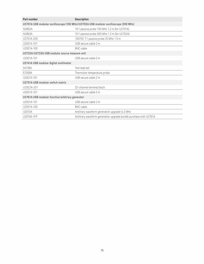
75
Part number Description
U2701A USB modular oscilloscope (100 MHz)/U2702A USB modular oscilloscope (200 MHz)
N2862A 10:1 passive probe 150 MHz 1.2 m (for U2701A)
N2863A 10:1 passive probe 300 MHz 1.2 m (for U2702A)
U2701A-200 10070C 1:1 passive probe 20 MHz 1.5 m
U2921A-101 USB secure cable 2 m
U2921A-100 BNC cable
U2722A/U2723A USB modular source measure unit
U2921A-101 USB secure cable 2 m
U2741A USB modular digital multimeter
34138A Test lead set
E2308A Thermistor temperature probe
U2921A-101 USB secure cable 2 m
U2751A USB modular switch matrix
U2922A-201 32-channel terminal block
U2921A-101 USB secure cable 2 m
U2761A USB modular function/arbitrary generator
U2921A-101 USB secure cable 2 m
U2921A-100 BNC cable
U2010A Arbitrary waveform generation upgrade to 2 MHz
U2010A-1FP Arbitrary waveform generation upgrade bundle purchase with U2761A

www.keysight.com/find/usbmodular
76 | Keysight | USB Modular Products - Data Sheet
This information is subject to change without notice.© Keysight Technologies, 2017Published in USA, December 1, 20175989-9923ENwww.keysight.com
For more information on Keysight Technologies’ products, applications or services, please contact your local Keysight office. The complete list is available at:www.keysight.com/find/contactus
Americas Canada (877) 894 4414Brazil 55 11 3351 7010Mexico 001 800 254 2440United States (800) 829 4444
Asia PacificAustralia 1 800 629 485China 800 810 0189Hong Kong 800 938 693India 1 800 11 2626Japan 0120 (421) 345Korea 080 769 0800Malaysia 1 800 888 848Singapore 1 800 375 8100Taiwan 0800 047 866Other AP Countries (65) 6375 8100
Europe & Middle EastAustria 0800 001122Belgium 0800 58580Finland 0800 523252France 0805 980333Germany 0800 6270999Ireland 1800 832700Israel 1 809 343051Italy 800 599100Luxembourg +32 800 58580Netherlands 0800 0233200Russia 8800 5009286Spain 800 000154Sweden 0200 882255Switzerland 0800 805353
Opt. 1 (DE)Opt. 2 (FR)Opt. 3 (IT)
United Kingdom 0800 0260637
For other unlisted countries:www.keysight.com/find/contactus(BP-9-7-17)
DEKRA CertifiedISO9001 Quality Management System
www.keysight.com/go/qualityKeysight Technologies, Inc.DEKRA Certified ISO 9001:2015Quality Management System
Evolving Since 1939Our unique combination of hardware, software, services, and people can help you reach your next breakthrough. We are unlocking the future of technology. From Hewlett-Packard to Agilent to Keysight.
myKeysightwww.keysight.com/find/mykeysightA personalized view into the information most relevant to you.
http://www.keysight.com/find/emt_product_registrationRegister your products to get up-to-date product information and find warranty information.
Keysight Serviceswww.keysight.com/find/serviceKeysight Services can help from acquisition to renewal across your instrument’s lifecycle. Our comprehensive service offerings—one-stop calibration, repair, asset management, technology refresh, consulting, training and more—helps you improve product quality and lower costs.
Keysight Assurance Planswww.keysight.com/find/AssurancePlansUp to ten years of protection and no budgetary surprises to ensure your instruments are operating to specification, so you can rely on accurate measurements.
Keysight Channel Partnerswww.keysight.com/find/channelpartnersGet the best of both worlds: Keysight’s measurement expertise and product breadth, combined with channel partner convenience.