journal week 6
DESCRIPTION
ÂTRANSCRIPT

Week 6
This week we were able to go to the workshop and build a bridge in pairs. We tested the amount of force that could be applied to our bridges till they snapped. Back in our tutorial room, we made a model of the new construction area of Queens College.
Activity: Structural Concepts’ (Part Two)
Stud -‐ a vertical framing member used to create walls and partitions. Studs can be either wood or metal.
Beneke, J. 2013. Stud. [online] Available at: http://garages.about.com/od/glossary/g/StudGlossary.htm [Accessed: 8 Sep 2013].
Akla and I were formed group four. Our materials were:
-‐ 1200 x 3.2 x 90 mm Plywood (x1) -‐ 1200 x 42 x 18 mm Pinewood (x3)
We cut one of the pine wood and spit it into 8 smaller blocks.
After nailing the first few blocks, the bridge was not stable. It could slide from side to side. Only after we a nailed all the blocks into the two, was it stable.
We did not need perfect measurements because the purpose was not to make the best bridge in aesthetics.
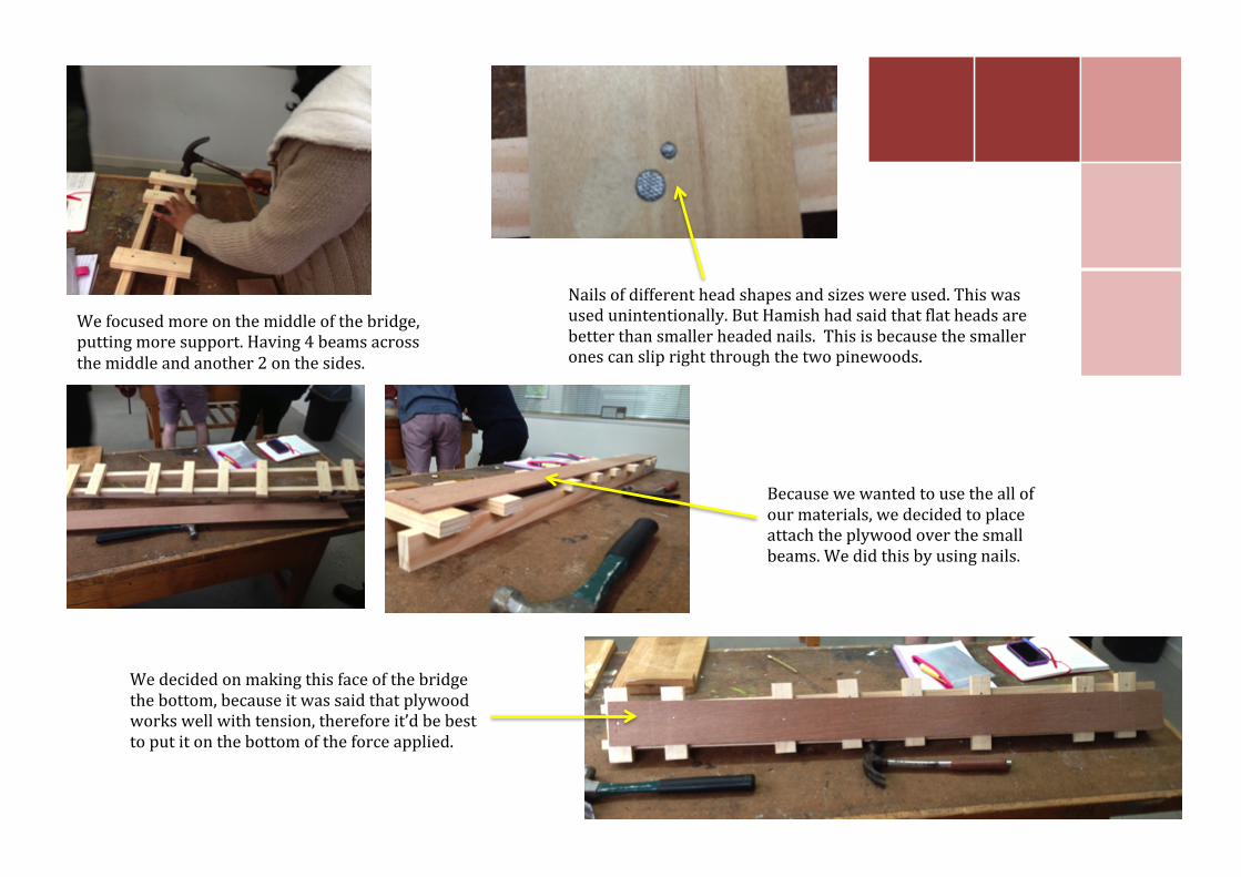
Nails of different head shapes and sizes were used. This was used unintentionally. But Hamish had said that flat heads are better than smaller headed nails. This is because the smaller ones can slip right through the two pinewoods.
We focused more on the middle of the bridge, putting more support. Having 4 beams across the middle and another 2 on the sides.
Because we wanted to use the all of our materials, we decided to place attach the plywood over the small beams. We did this by using nails.
We decided on making this face of the bridge the bottom, because it was said that plywood works well with tension, therefore it’d be best to put it on the bottom of the force applied.

Group 1: -‐ Plywood x2 -‐ Pinewood x2
Group 2: -‐ Plywood x2 -‐ Pinewood x2
The maximum applied force on the bridge before it snapped, was 350 kg.
Shear force plays a lot in the snap of the bridge.
Before the plywood at the bottom was snapped, it was still holding. This is because the force that the plywood at the bottom underwent was tension, and plywood works well with tension as it is very flexible.
The part that was snapped was where the nails were hit into, making that area weaker.
Group two had a similar designed bridge as group one. This is why we tested the bridge from another side.
We found that the flatter headed nails were better, because they do not go straight through the pinewood like the smaller nails do.
The top was badly crushed. The plywood also eventually snapped with the pinewood that was under all the force.
The bottom pinewood remained unharmed as it was on the bottom, but the plywood kept bending away from the bridge, braking away from the nail.

Group 3: -‐ Plywood x1 -‐ Pinewood x3
Group 4: -‐ Plywood x1 -‐ Pinewood x3
This group’s bridge survived the most amount of force that was applied. It reached up to 380 kg of force.
The screws they used held all ends well with the plywood.
When the screws were screwed in, it sometimes split the timber apart because it did not follow the direction of the grain, making it weaker
There was some bending coming from the plywood showcasing tis flexibility.
The screws worked better than the nails, although the crack was found at the area where the nail or screw was put in.
Our group’s bridge survived at the force of 230 kg.
The plywood was put at the bottom because it was said that it works well with tension instead of compression.
It was found that when the force was applied to the bridge, the bridge broke at the nail. This is because once the nail is hammered into the timber, it makes it weaker.

Queens College Model
Using tracing paper, we went over the floor plans of Queens College of the area that is being built.
The walls are made from concrete, which is why we used this coloured, cardboard. By reading off the plans of Queens College, we found the height of the walls, keeping the scales the same.
The courtyard is exposed aggregate concrete
Stairs