journal of membrane science - the mccutcheon lab · journal of membrane science 375 (2011) 55–62...
TRANSCRIPT

Spr
Ja
b
c
a
ARRAA
KFPTEPHM
1
oircip
tnmmtmparn
0d
Journal of Membrane Science 375 (2011) 55–62
Contents lists available at ScienceDirect
Journal of Membrane Science
journa l homepage: www.e lsev ier .com/ locate /memsci
urface modification of thin film composite membrane support layers witholydopamine: Enabling use of reverse osmosis membranes in pressureetarded osmosis
ason T. Arenaa, Bryan McCloskeyb, Benny D. Freemanc, Jeffrey R. McCutcheona,∗
University of Connecticut, Department of Chemical, Materials and Biomolecular Engineering and the Center for Environmental Sciences and Engineering, Storrs, CT 06269, USAIBM Almaden Research Center, 650 Harry Rd., San Jose, CA 95120University of Texas, Department of Chemical Engineering, Austin, TX 78712, USA
r t i c l e i n f o
rticle history:eceived 23 December 2010eceived in revised form 28 January 2011ccepted 30 January 2011vailable online 5 February 2011
a b s t r a c t
Previous investigations of forward osmosis and pressure retarded osmosis identified asymmetric mem-brane support layer hydrophilicity as critical to obtain high water flux. In this study, the support layers oftwo commercially available thin film composite reverse osmosis membranes were modified to enhancetheir hydrophilicity. The membrane support layers were coated with polydopamine, a novel bio-inspiredhydrophilic polymer. This resulted in increased hydrophilicity and a corresponding increase in ‘wettedporosity’ and reduced internal concentration polarization. The modified membranes were then character-
eywords:orward osmosisressure retarded osmosishin film composite membranengineered osmosisolydopamine
ized for contact angle, salt rejection, hydraulic permeability, salt flux, and osmotic flux. The results werepromising, indicating that the modified reverse osmosis membranes exhibited an eight to fifteen foldincrease in flux performance under test conditions when compared to baseline control data. This mod-ification method, which is scalable, has the potential to enable the use of existing thin film compositemembranes for all engineered osmosis applications.
ydrophilicityembrane modification
. Introduction
Engineered osmosis (EO) offers the possibility for utilizingsmotic pressure gradients for a wide range of applications. Thesenclude forward osmosis (FO) for water desalination, pressureetarded osmosis (PRO) for power generation and direct osmoticoncentration (DOC) for dewatering. Poor performance of exist-ng membranes has, however, limited the growth of this emerginglatform technology [1–6].
Current thin film composite (TFC) membranes are highly selec-ive and permeable during hydraulically driven flow, such asanofiltration (NF) and reverse osmosis (RO) [7–9]. The perfor-ance of TFC membranes far exceeds that of integrated asymmetricembranes for pressure driven flow [9], but these benefits do not
ranslate to EO processes. Poor performance of commercial TFC ROembranes in EO is attributed to severe internal concentration
olarization (CP) caused by the thick porous support layers thatre universal to these type of membranes [10,11]. Recent effortseported that internal CP may be enhanced by the hydrophobicature of typical TFC support layers. The intrinsic hydrophobicity
∗ Corresponding author. Tel.: +1 860 486 4601.E-mail address: [email protected] (J.R. McCutcheon).
376-7388/$ – see front matter © 2011 Elsevier B.V. All rights reserved.oi:10.1016/j.memsci.2011.01.060
© 2011 Elsevier B.V. All rights reserved.
of the polysulfone (PSu) support mid-layer and the polyester (PET)nonwoven prevents complete wetting of the pore structure. Thereduction in ‘wetted porosity’ of the support layer reduces solutediffusivity and available pathways for water transport [12]. This isone reason that the only commercially available forward osmosis(FO) membrane from Hydration Technologies Innovations (HTI) iscomprised of cellulose acetate, a hydrophilic polymer [13].
1.1. Using membranes with intrinsically hydrophilic supportlayers
Several groups are considering the fabrication of integratedmembranes for forward osmosis using hydrophilic polymers suchas polybenzimidazole (PBI) and cellulose acetate (CA) [14–17].While hydrophilic polymers may be suitable for integrated mem-brane fabrication, they are not likely to function as an adequate TFCmembrane support. If the entire porous support membrane werehydrophilic, it could absorb water, swell and soften (plasticize) [18].Additionally, if the membrane support were hydrophilic, it might
swell differently in different media (e.g., pure water vs. saltwater),contributing to mechanical instability [19]. Support layer swellingmay also cause post-fabrication perforation or delamination of theselective layer. It is therefore advantageous to use hydrophobic andtough thermoplastics for membrane supports.
5 mbra
msmtwplpt
iewaffly
1
pa[roioeamtblet6
wtsAmiatc
u[latfci
2
2
W
6 J.T. Arena et al. / Journal of Me
Additionally, other complications may arise if hydrophilic poly-ers are used as supports for TFC membranes. According to a recent
tudy, support layer hydrophobicity may influence interfacial poly-erization due to the shape of the meniscus that forms between
he organic and aqueous phase. The hydrophilicity of the supportill alter the shape of the meniscus which will affect the resultingolyamide properties [20]. The surface chemistry of the support
ayer may also interact with the amine monomer during interfacialolymerization. These phenomena cause changes in the resultinghin film properties and a reduction in selectivity.
Research using hydrophilic polymers in TFC membrane supportss at the time of this writing still in its infancy. Nevertheless, thesearly efforts have indicated that if we wish to use a TFC membraneith a hydrophilic support layer, imparting the hydrophilic char-
cter to the support layer after the composite structure has beenully formed may be a preferred approach. This allows us to takeull advantage of the superior permselectivity of the polyamideayer that has been optimized for performance for the past thirtyears.
.2. Use of polydopamine for increasing hydrophilicity of surfaces
Polydopamine is a novel bio-inspired polymer sharing similarroperties to the adhesive secretions of mussels and is capable ofdhering to substrates underwater and without surface preparation21,22]. This polymer is formed by a polymerization/precipitationeaction using low concentrations of dopamine in an aerated aque-us solution at basic pHs. Though the mechanism of PDA formations still undergoing investigation, one proposed mechanism consistsf three primary steps; the first is the requisite oxidation of the cat-chol functionality to a benzoquinone, cyclization of the primarymine yielding 5,6-dihydroxindole, and the polymerization of thisonomer [21–23]. The 5,6-dihydroxindole can then adsorb onto
he substrate’s surface as a result of hydrogen bonding permissibleecause of the catechol moiety. This process results in a layer-by-
ayer assembly of PDA onto the substrate [24]. Various studies havexamined the thickness of the PDA coating; upon termination ofhe polymerization step PDA layer thicknesses of between 20 and5 nm were reported [22,25,26].
PDA can be applied to wide variety of materials including thosehich are considered highly resistance to adhesion such as poly-
etrafluoroethylene (PTFE) [21]. Additionally, inorganic materialsuch as metals and metal oxides can be coated with PDA [22,24,25].nother unique and useful property of PDA is its ability to scavengeetals out of solution and incorporate them into a PDA surface coat-
ng via an electroless metallization [24]. Furthermore when PDA ispplied to a material its surface properties dominate over those ofhe substrate allowing for the compatibilization of organic fibers orarbon nanotubes [27,28].
Recently, PDA has been used to impart fouling resistance toltrafiltration and reverse osmosis and nanofiltration membranes26]. In these investigations, the PDA was applied to the selectiveayer and shown to increase hydrophilicity. This resulted in reduceddhesion to the surface by proteins and other foulants. In additiono this direct application of hydrophilic PDA surface layers to impartouling resistance; amine functionalized polyethylene glycol (PEG)an be covalently bonded to a membrane surface further enhancingts fouling resistance [26].
. Materials and methods
.1. Selected membranes and chemicals
The membranes selected for this investigation are the Dowater & Process Solutions BW30 and SW30-XLE membranes.
ne Science 375 (2011) 55–62
Both membranes support layers are made of PSu supported by aPET nonwoven [8]. They were chosen for their well documentedability of rejecting sodium chloride ions as well as the inher-ent benefits of being able to source consistent substrates for PDAmodification [29,30]. The sodium chloride, Tris–HCl, and sodiumhydroxide were purchased from Fisher Scientific (Pittsburgh, PA).The dopamine–hydrochloride was purchased from Sigma–Aldrich(St. Louis, MO). The water used was ultrapure Milli-Q waterproduced by a Millipore Integral 10 water system (Millipore Cor-poration Billerica, MA).
2.2. Scanning electron microscope imaging of TFC RO membranes
The TFC membrane PSu layer pore structures were imagedwith a FEI Phenom scanning electron microscope (SEM) from FEICompany (Hillsboro, OR). These samples were prepared using afreeze fracturing technique involving liquid nitrogen [31–33] afterremoval of the PET support layer. This method allows the prepara-tion of clean, straight edges and a preserved internal pore structurefor observation.
2.3. Preparation of membranes for coating
The membranes were taken as is from Dow and prepared forcoating. First, the polyester (PET) fabric layer was removed by care-fully peeling the layer from the porous PSu layer while taking careto not damage the selective layers of the membrane [12]. This wasdone to expose the more hydrophobic PSu directly to the PDA coat-ing solution. The membranes with no PET were then placed indeionized water for storage.
Prior to coating the membrane with PDA, the membrane issoaked in isopropyl alcohol (IPA) at room temperature for 1 h towet out the pore structure. Wetting of the PSu pore structure withwater is essential for coating because PDA polymerization occursonly within aqueous solution as a result of the need for hydroxidegroups to facilitate functionalization of dopamine for polymeriza-tion [22]. The IPA is then rinsed out of the membranes using aseries of three deionized (DI) water baths of 1 L volume for 45 mineach [26]. The DI water rinsing baths are refrigerated to preventthe nucleation of air bubbles on the surface and into the pores ofthe membranes and thus jeopardize the pore wetting. After the IPAhas been washed out of the membranes they are stored at 5 ◦C indeionized water.
2.4. Coating membrane support layers with PDA
The coating step takes place at room temperature and was per-formed in a custom designed coating device which limits coatingto only one side of the membrane. The container has two reser-voirs separated by the membrane. The PDA coating solution isplaced in the reservoir exposed to the PSu layer and is added astwo components: 100 mL of a pH 8.7 Tris–HCl buffer and 2 mL of a100 g/L solution of dopamine [21,22,24–28]. The reservoir in con-tact with the selective layer contains the same pH 8.7 Tris–HClbuffer solution, without dopamine–HCl, to balance out a majorityof concentration gradients across the membrane. Having a solu-tion in contact with the selective layer is essential to ensure thatthe membranes selective layer remains hydrated.
Coating times for PDA can vary but this investigation was limitedto a short coating time of 1 h and a long coating time of 42 h. 42 hshould be sufficient for the PDA coating thickness to have attained amaximum given the reagents [21,25,26]. A diagram illustrating themembrane preparation and coating process is provided in Fig. 1.

J.T. Arena et al. / Journal of Membrane Science 375 (2011) 55–62 57
or mo
2
PoLa
2
cihnmswnFbnbpfie2rca
2
fl[wmbwtif
Fig. 1. Flowchart showing the process f
.5. Determination of contact angles
The contact angles of the peeled and PDA modified membranesSu support layers were measured using the sessile drop methodn a CAM 101 series contact angle goniometer (KSV Companyinthicum Heights, MD). The values were taken as an average oft least four points with a volume of 10 ± 1 �L.
.6. Testing hydraulically driven flux of modified membranes
The peeled and PDA modified membranes were subjected toross-flow RO tests to determine if the PET removal or PDA coat-ng process altered the membrane permselectivity. Previous workas indicated that PET removal, if done carefully resulted in no sig-ificant loss of selectivity [12]. Moreover, it is unlikely that PDAodification of the support layer would damage the polyamide
elective layer and reduce selectivity. To ensure these results, pureater permeability and salt rejection tests were performed on theeat and modified membranes in a lab-scale cross-flow RO system.or these tests, the removed PET was inserted behind the mem-rane to serve as additional support. This additional support doesot contribute significantly to the hydraulic resistance of the mem-rane and will not impact the pure water permeability. Pure waterermeability tests were conducted at 25 ◦C at five pressures rangingrom 150 to 450 pounds per square inch (psi). Flux was measuredn duplicate with very close agreement as observable by the smallrror bars. The salt rejection tests were conducted with a feed of000 parts per million (ppm) sodium chloride at 25 ◦C at a volumet-ic flow rate of 0.5 L/min. Permeate for the salt rejection tests wereollected at 225 and 450 psi. The conductivity of the bulk permeatend feed were measured to determine the rejection.
.7. Testing osmotically driven flux of modified membranes
The modified TFC RO membranes were tested under osmoticux conditions using a method similar to previous investigations5,33]. In these tests, the membrane was oriented in the PRO mode,ith the selective layer facing the draw solution [10]. Flux waseasured across both the SW30–XLE and the BW30 membranes
efore and after each step of the modification described above. Fluxas measured on the neat membranes (as received from Dow),
he membranes lacking the PET layer, and the membranes lack-ng the PET layer after PDA coating of the PSu support structureor 1 and 42 h. Sodium chloride was used as the draw solute at
difying a TFC RO membrane with PDA.
concentrations of 0.05, 0.1, 0.5, 1.0, and 1.5 M. The system incor-porated a recirculating chiller and temperature was maintained at23 ◦C ± 1. The osmotic pressures produced by these draw solutionswere calculated using the modified van’t Hoff equation [34]. Testswere run in triplicate using fresh membrane samples and eachhad been modified independently using the technique describedpreviously.
2.8. Flux modeling for evaluating coating efficacy
A model was developed to compare the actual performance ofthe PDA modified membranes to that of an ideal membrane witha fully wetted support layer and perfect selectivity. The model wasdeveloped in previous investigations [10,35]. Since the membranewas oriented in the PRO mode, we can assume minimal salt passagethrough the membranes selective layer and predict the flux throughthe membrane based solely on the pure water permeability, thedraw solution osmotic pressure, and the external concentrationpolarization modulus [33].
Jw = A · �D exp(
− Jwk
)(1)
where Jw is the water flux, A is the hydraulic permeability, �D isthe osmotic pressure of the draw solution and k is the externalmass transfer coefficient on the draw side of the membrane. Givena known mass transfer coefficient, hydraulic permeance, and drawsolution osmotic pressure, flux is solved iteratively using a MatLabprogram coded by the author.
3. Results and discussion
3.1. Polysulfone pore structure
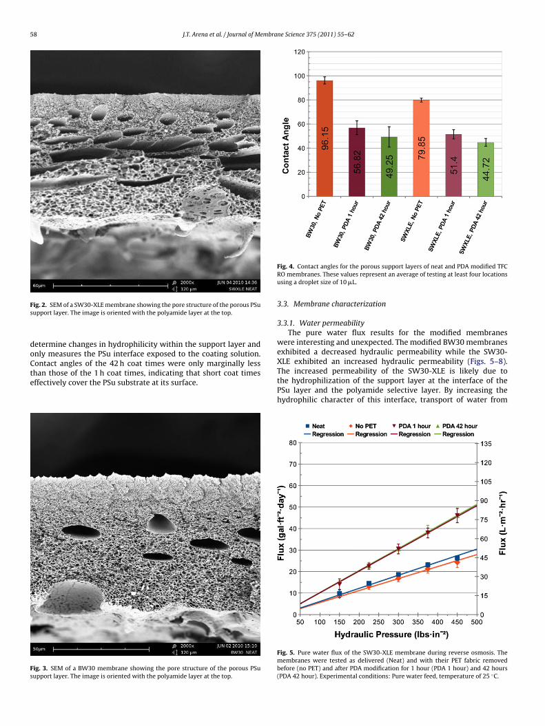
SEM images of the polysulfone layers of the SW30-XLE andBW30 membranes are shown in Figs. 2 and 3, respectively. TheSW30-XLE PSu layer is more porous and contains large numbers ofmacrovoids. The BW30’s PSu layer contains fewer macrovoids andin general smaller pores.
3.2. Contact angle
Fig. 4 shows that the PDA coating resulted in a decrease in con-tact angle for both the SW30-XLE and BW30 PSu layers indicatingan increased hydrophilicity. It is noted that this technique does not
58 J.T. Arena et al. / Journal of Membrane Science 375 (2011) 55–62
Fs
doCte
Fs
ig. 2. SEM of a SW30-XLE membrane showing the pore structure of the porous PSuupport layer. The image is oriented with the polyamide layer at the top.
etermine changes in hydrophilicity within the support layer andnly measures the PSu interface exposed to the coating solution.ontact angles of the 42 h coat times were only marginally less
han those of the 1 h coat times, indicating that short coat timesffectively cover the PSu substrate at its surface.ig. 3. SEM of a BW30 membrane showing the pore structure of the porous PSuupport layer. The image is oriented with the polyamide layer at the top.
Fig. 4. Contact angles for the porous support layers of neat and PDA modified TFCRO membranes. These values represent an average of testing at least four locationsusing a droplet size of 10 �L.
3.3. Membrane characterization
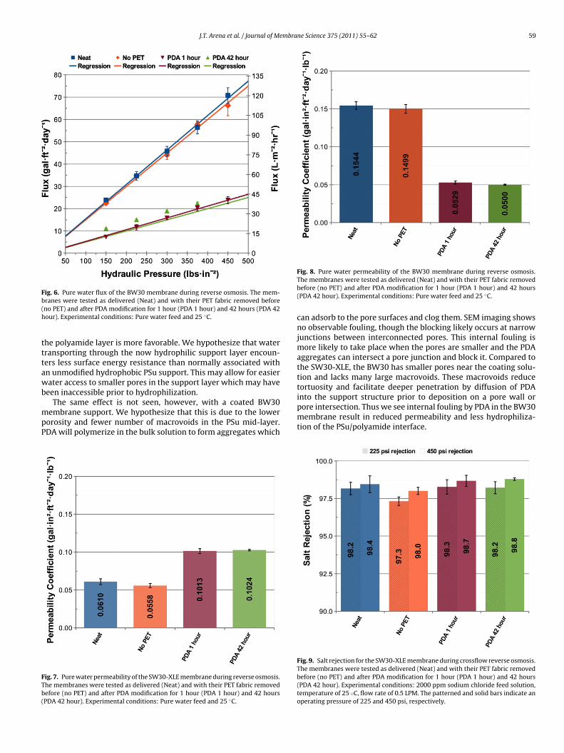
3.3.1. Water permeabilityThe pure water flux results for the modified membranes
were interesting and unexpected. The modified BW30 membranesexhibited a decreased hydraulic permeability while the SW30-XLE exhibited an increased hydraulic permeability (Figs. 5–8).
The increased permeability of the SW30-XLE is likely due tothe hydrophilization of the support layer at the interface of thePSu layer and the polyamide selective layer. By increasing thehydrophilic character of this interface, transport of water fromFig. 5. Pure water flux of the SW30-XLE membrane during reverse osmosis. Themembranes were tested as delivered (Neat) and with their PET fabric removedbefore (no PET) and after PDA modification for 1 hour (PDA 1 hour) and 42 hours(PDA 42 hour). Experimental conditions: Pure water feed, temperature of 25 ◦C.
J.T. Arena et al. / Journal of Membrane Science 375 (2011) 55–62 59
Fb(h
tttawb
mpP
FTb(
tortuosity and facilitate deeper penetration by diffusion of PDAinto the support structure prior to deposition on a pore wall or
ig. 6. Pure water flux of the BW30 membrane during reverse osmosis. The mem-ranes were tested as delivered (Neat) and with their PET fabric removed beforeno PET) and after PDA modification for 1 hour (PDA 1 hour) and 42 hours (PDA 42our). Experimental conditions: Pure water feed and 25 ◦C.
he polyamide layer is more favorable. We hypothesize that waterransporting through the now hydrophilic support layer encoun-ers less surface energy resistance than normally associated withn unmodified hydrophobic PSu support. This may allow for easierater access to smaller pores in the support layer which may have
een inaccessible prior to hydrophilization.
The same effect is not seen, however, with a coated BW30embrane support. We hypothesize that this is due to the lowerorosity and fewer number of macrovoids in the PSu mid-layer.DA will polymerize in the bulk solution to form aggregates which
ig. 7. Pure water permeability of the SW30-XLE membrane during reverse osmosis.he membranes were tested as delivered (Neat) and with their PET fabric removedefore (no PET) and after PDA modification for 1 hour (PDA 1 hour) and 42 hoursPDA 42 hour). Experimental conditions: Pure water feed and 25 ◦C.
Fig. 8. Pure water permeability of the BW30 membrane during reverse osmosis.The membranes were tested as delivered (Neat) and with their PET fabric removedbefore (no PET) and after PDA modification for 1 hour (PDA 1 hour) and 42 hours(PDA 42 hour). Experimental conditions: Pure water feed and 25 ◦C.
can adsorb to the pore surfaces and clog them. SEM imaging showsno observable fouling, though the blocking likely occurs at narrowjunctions between interconnected pores. This internal fouling ismore likely to take place when the pores are smaller and the PDAaggregates can intersect a pore junction and block it. Compared tothe SW30-XLE, the BW30 has smaller pores near the coating solu-tion and lacks many large macrovoids. These macrovoids reduce
pore intersection. Thus we see internal fouling by PDA in the BW30membrane result in reduced permeability and less hydrophiliza-tion of the PSu/polyamide interface.
Fig. 9. Salt rejection for the SW30-XLE membrane during crossflow reverse osmosis.The membranes were tested as delivered (Neat) and with their PET fabric removedbefore (no PET) and after PDA modification for 1 hour (PDA 1 hour) and 42 hours(PDA 42 hour). Experimental conditions: 2000 ppm sodium chloride feed solution,temperature of 25 ◦C, flow rate of 0.5 LPM. The patterned and solid bars indicate anoperating pressure of 225 and 450 psi, respectively.

60 J.T. Arena et al. / Journal of Membrane Science 375 (2011) 55–62
Fig. 10. Salt rejection for the BW30 membrane during crossflow reverse osmosis.The membranes were tested as delivered (Neat) and with their PET fabric removedb(to
3
iTp
3
3
moptb
miflflowf
tp
TWb
however, the less hydraulically permeable SW30-XLE membraneexhibited approximately 20% higher flux when compared to theBW30 (Figs. 11 and 12). It is thought that this has to do withthe macropores present in the SW30 membrane, which resultsin a decreased tortuosity and larger pore size compared to the
efore (no PET) and after PDA modification for 1 hour (PDA 1 hour) and 42 hoursPDA 42 hour). Experimental conditions: 2000 ppm sodium chloride feed solution,emperature of 25 ◦C, flow rate of 0.5 LPM. The patterned and solid bars indicate anperating pressure of 225 and 450 psi, respectively.
.3.2. Salt rejectionAverage salt rejections for the modified membranes are shown
n Figs. 9 and 10. The fluxes for the tests can be found in Table 1.hese results show that the PDA modified membranes have com-arable selectivity to the unaltered membranes.
.4. Osmotic flux testing
.4.1. Water fluxTo evaluate the impact of PDA coating on the commercial
embranes for PRO applications, the membranes were tested forsmotic flux in the PRO mode. The coated membranes were com-ared to the neat (unaltered) membranes both with and withouthe PET layer. The results from both the SW30-XLE and BW30 mem-ranes are shown in Figs. 11 and 12, respectively.
For both membranes, flux performance was poor for the neatembrane and the membrane lacking a PET backing. This result
s consistent with other studies using RO membranes in osmoticux tests [5,12]. The PDA modified membrane exhibited substantialux improvement, indicative of an increase in the ‘wetted porosity’f the membrane support layer. This increased wetting promotes
ater transport through the support layer and to the interior inter-ace of the polyamide layer.The increased wetted porosity also promotes salt diffusion
hrough the support layer after it diffuses across the selectiveolyamide layer. Internal concentration polarization occurs as a
able 1ater flux for a 2000 ppm sodium chloride solution for neat and modified mem-
ranes at 25 ◦C with a flow rate of 0.5 LPM.
SWXLENeat
SWXLENo PET
SWXLEPDA 1 h
SWXLEPDA 42 h
225 psi 12.82 ± 1.38 10.89 ± 0.35 17.06 ± 2.58 18.49 ± 1.52450 psi 27.11 ± 2.91 23.28 ± 0.73 39.57 ± 3.08 37.75 ± 2.35
BW30Neat
BW30No PET
BW30PDA 1 h
BW30PDA 42 h
225 psi 25.88 ± 2.35 25.53 ± 1.45 9.59 ± 0.81 9.38 ± 0.20450 psi 54.40 ± 5.44 54.28 ± 4.48 21.41 ± 1.07 19.74 ± 0.28
Fig. 11. Osmotic flux performance of neat and modified SW30-XLE membranesusing a NaCl draw solution at 0.05, 0.1, 0.5, 1.0, and 1.5 M concentration. Tests wererun at 23 ◦C with a flow rate of 1 LPM. The membranes were oriented in the PROmode.
result of salt crossover [10,12,33]. If this salt is not permitted toeasily diffuse out of the membrane support, it will increase in con-centration and drastically reduce water flux. Since no salt is presentin the dilute solution at the start of the test, this salt crossoverwould be the only source of internal concentration polarizationunder these test conditions.
Significant water flux improvements were observed for both theBW30 and SW30-XLE membranes following a PDA modification;
Fig. 12. Osmotic flux performance of neat and modified BW30 membranes using aNaCl draw solution at 0.05, 0.1, 0.5, 1.0, and 1.5 M concentration. Tests were run at23 ◦C with a flow rate of 1 LPM. The membranes were oriented in the PRO mode.

J.T. Arena et al. / Journal of Membrane Science 375 (2011) 55–62 61
FmTt
Bi
fpttiBth
FbTt
Fig. 15. Comparison between the osmotic flux data in Fig. 11 and the modeled idealflux for the SW30-XLE membrane. The modeled data assumes only external con-
concentration and used to determine the salt flux of the membrane(Figs. 13 and 14). Generally, increased flux performance has been
ig. 13. Salt flux during the osmosis tests for the neat and modified SW30-XLEembranes using a NaCl draw solution at 0.05, 0.1, 0.5, 1.0, and 1.5 M concentration.
ests were run at 23 ◦C with a flow rate of 1 LPM. The membranes were oriented inhe PRO mode.
W30. This results in decreased internal concentration polarizationnduced by salt crossover [33].
There are also flux differences between the 1 and 42 h coat timesor each membrane. The SW30-XLE membrane exhibits similar fluxerformance for both coat times, while the BW30 indicates a reduc-ion in flux for increased coat times. This supports the hypothesis
hat the macroporous structure of the BW30 membrane supports prone to pore clogging during the coating process. Some of theW30 pores are blocked during the coating process, increasing theortuosity of the structure and enhancing internal CP in addition toampering water transport to the PSu/polyamide interface.ig. 14. Salt flux during the osmosis tests for the neat and modified BW30 mem-ranes using a NaCl draw solution at 0.05, 0.1, 0.5, 1.0, and 1.5 M concentration.ests were run at 23 ◦C with a flow rate of 1 LPM. The membranes were oriented inhe PRO mode.
centration polarization is present. The shaded area indicates the expected flux fora membrane based upon the highest and lowest measured permeability from purewater tests. The solid curve is the modeled flux using the permeability of the PDAcoated membrane and the dashed curve is based off of the permeability of the neatmembrane.
3.4.2. Salt fluxThe conductivity of the feed solution was measured before and
after each flux measurement. This value was correlated to a salt
correlated with increased salt flux. This is not unexpected giventhat salt generates the driving force for water flux. Such a resulthas also been observed by others [32,36]. It is worth noting that an
Fig. 16. Comparison between the osmotic flux data in Fig. 12 and the modeled idealflux for the BW30 membrane. The modeled data assumes only external concen-tration polarization is present. The shaded area indicates the expected flux for amembrane based upon the highest and lowest measured permeability from purewater tests. The solid curve is the modeled flux using the permeability of the PDAcoated membrane and the dashed curve is based off of the permeability of the neatmembrane.

6 mbra
icltw
3
nfldfl
mordFflc
4
cimmfiippp
oicba
A
FNW
R
[
[
[
[
[
[
[
[
[
[
[
[
[
[
[
[
[
[
[
[
[
[
[
[
[
[
2 J.T. Arena et al. / Journal of Me
ncreased salt flux into the feed solution is indicative of less internaloncentration polarization. If salts are diffusing out of the supportayer with greater ease, they are not residing in the support layerhus resulting in a reduced osmotic driving force. Increasing theetted porosity thus increases both salt and water flux.
.5. Flux modeling
Flux was modeled based on the pure water permeance of theeat and modified SW30 XLE and BW30 membranes as determined
rom RO. Mass transfer coefficients on the draw side were calcu-ated with appropriate Sherwood number correlations as has beenone in previous investigations [35,37]. Eq. (1) was used to predictux given these known values.
Since we are not certain whether the neat or the modifiedembrane water permeability is the effective permeability for
smotically driven water flux, the modeled flux data contains aange of values for both permeability values. Though the modeloes not take into account salt crossover induced internal CP,igs. 15 and 16 indicate that there is significant room for furtherux enhancement for both membranes through an improved PDAoating protocol.
. Conclusions
The data shows that modifying the support layers of commer-ial thin film composite membranes with polydopamine resultedn significant improvement in osmotic flux performance of these
embranes when oriented in the PRO mode. This flux enhance-ent is due to a radically increased “wetted porosity” which
acilitates water transport through the support layer and decreasednternal CP caused by salt crossover from the draw solution. Thencreased hydrophilicity also results in a two times higher hydraulicermeability for the SW30-XLE membrane but a reduction in waterermeability for the BW30 caused by the difference in porous sup-ort structure.
The scalability of this process renders it viable for modificationf traditional thin film composite membranes after fabrication. Its the authors’ hope that refinement and enhancement to the PDAoating methodology will produce further improvements to mem-rane performance in PRO. Further tests on the coating longevitynd stability will be evaluated in follow on work.
cknowledgements
The authors acknowledge funding from the National Scienceoundation GK-12 Program and the Department of Energy/Pacificorthwest National Laboratory. The authors also wish to thank Dowater & Process Solutions for providing membranes for this study.
eferences
[1] R.L. McGinnis, M. Elimelech, Global challenges in energy and water supply: thepromise of engineered osmosis, Environmental Science and Technology 42 (23)(2008) 8625–8629.
[2] R.E. Kravath, J.A. Davis, Desalination of sea water by direct osmosis, Desalination16 (2) (1975) 151–155.
[3] J.O. Kessler, C.D. Moody, Drinking water from sea water by forward osmosis,Desalination 18 (3) (1976) 297–306.
[4] K.L. Lee, R.W. Baker, H.K. Lonsdale, Membranes for power generation bypressure-retarded osmosis, Journal of Membrane Science 8 (2) (1981) 141–171.
[5] J.R. McCutcheon, R.L. McGinnis, M. Elimelech, A novel ammonia–carbon diox-ide forward (direct) osmosis desalination process, Desalination 174 (1) (2005)
1–11.[6] T.Y. Cath, A.E. Childress, M. Elimelech, Forward osmosis: principles, applica-tions, and recent developments, Journal of Membrane Science 281 (1–2) (2006)70–87.
[7] R.J. Petersen, Composite reverse osmosis and nanofiltration membranes, Jour-nal of Membrane Science 83 (1) (1993) 81–150.
[
[
ne Science 375 (2011) 55–62
[8] FILMTEC Reverse Osmosis Membranes Technical Manual, Form No. 609-00071-1009, Dow Water & Process Solutions.
[9] J.E. Cadotte, R.J. Petersen, R.E. Larson, E.E. Erickson, A new thin-film compositeseawater reverse osmosis membrane, Desalination 32 (1980) 25–31.
10] J.R. McCutcheon, M. Elimelech, Influence of concentrative and dilutive inter-nal concentration polarization on flux behavior in forward osmosis, Journal ofMembrane Science 284 (1–2) (2006) 237–247.
11] J.R. McCutcheon, R.L. McGinnis, M. Elimelech, Desalination byammonia–carbon dioxide forward osmosis: influence of draw and feedsolution concentrations on process performance, Journal of Membrane Science278 (1–2) (2006) 114–123.
12] J.R. McCutcheon, M. Elimelech, Influence of membrane support layer hydropho-bicity on water flux in osmotically driven membrane processes, Journal ofMembrane Science 318 (1–2) (2008) 458–466.
13] J. Herron, Asymmetric Forward Osmosis Membranes, US007445712B2, UnitedStates, 2008.
14] S. Zhang, K.Y. Wang, T.-S. Chung, H. Chen, Y.C. Jean, G. Amy, Well-constructedcellulose acetate membranes for forward osmosis: minimized internal con-centration polarization with an ultra-thin selective layer, Journal of MembraneScience 360 (1–2) (2010) 522.
15] K.Y. Wang, T.-S. Chung, J.-J. Qin, Polybenzimidazole (PBI) nanofiltration hollowfiber membranes applied in forward osmosis process, Journal of MembraneScience 300 (1–2) (2007) 6.
16] K.Y. Wang, Q. Yang, T.-S. Chung, R. Rajagopalan, Enhanced forward osmosisfrom chemically modified polybenzimidazole (PBI) nanofiltration hollow fibermembranes with a thin wall, Chemical Engineering Science 64 (7) (2009) 1577.
17] K.Y. Wang, R.C. Ong, T.-S. Chung, Double-skinned forward osmosis membranesfor reducing internal concentration polarization within the porous sublayer,Industrial and Engineering Chemistry Research 49 (10) (2010) 4824.
18] R.F. Eaton, R.J. Roe, G.L. Wilkes, A.V. Tobolsky, Thermodynamics of HydrophilicPolymer Membranes: The Degree of Swelling and Salt Partition Coefficient, vol.35 (n), American Chemical Society, Division of Organic Coatings and PlasticsChemistry, Preprints, 1975, pp. 503–508.
19] J.L. Bert, I. Fatt, D. Saraf, Dynamics of water transport in cellulose acetate, TheSwelling Phenomenon (13) (1970) 105–119.
20] A.K. Ghosh, E.M.V. Hoek, Impacts of support membrane structure and chem-istry on polyamide–polysulfone interfacial composite membranes, Journal ofMembrane Science 336 (1–2) (2009) 140–148.
21] H. Lee, J. Rho, P.B. Messersmith, Facile conjugation of biomolecules onto sur-faces via mussel adhesive protein inspired coatings, Advanced Materials 21 (4)(2009) 431–434.
22] H. Lee, S.M. Dellatore, W.M. Miller, P.B. Messersmith, Mussel-inspired surfacechemistry for multifunctional coatings, Science 318 (5849) (2007) 426–430.
23] P.B. Messersmith, H. Lee, Suface-Independent, Surface-Modifying Multifunc-tional Coatings and Applications thereof, US 2008/0149566 Al United States,2008.
24] H. Lee, Y. Lee, A.R. Statz, J. Rho, T.G. Park, P.B. Messersmith, Substrate-independent layer-by-layer assembly by using mussel-adhesive-inspiredpolymers, Advanced Materials 20 (9) (2008) 1619–1623.
25] A. Postma, Y. Yan, Y. Wang, A.N. Zelikin, E. Tjipto, F. Caruso, Self-polymerizationof dopamine as a versatile and robust technique to prepare polymer capsules,Chemistry of Materials 21 (14) (2009) 3042–3044.
26] B.D. McCloskey, H.B. Park, H. Ju, B.W. Rowe, D.J. Miller, B.J. Chun, K. Kin, B.D.Freeman, Influence of polydopamine deposition conditions on pure water fluxand foulant adhesion resistance of reverse osmosis, ultrafiltration, and micro-filtration membranes, Polymer 51 (15) (2010) 3472–3485.
27] A. Bourmaud, J. Riviere, A. Le Duigou, G. Raj, C. Baley, Investigations of the useof a mussel-inspired compatibilizer to improve the matrix-fiber adhesion of abiocomposite, Polymer Testing 28 (6) (2009) 668–672.
28] B. Fei, B. Qian, Z. Yang, R. Wang, W.C. Liu, C.L. Mak, J.H. Xin, Coating carbonnanotubes by spontaneous oxidative polymerization of dopamine, Carbon 46(13) (2008) 1795–1797.
29] Dow FILMTEC Membranes BW30-440i Product Information, Form No. 609-00482-0910 Dow Water & Process Solutions.
30] Dow FILMTEC Membranes SW30XLE-440i Product Information, Form No. 609-03003-1109 Dow Water & Process Solutions.
31] R.R. Ferlita, D. Phipps, J. Safarik, D.H. Yeh, Cryo-snap: a simple modified freeze-fracture method for SEM imaging of membrane cross-sections, EnvironmentalProgress 27 (2) (2008) 204–209.
32] W.A. Phillip, J.S. Yong, M. Elimelech, Reverse draw solute permeation in forwardosmosis: modeling and experiments, Environmental Science and Technology44 (13) (2010) 5170–5176.
33] G.T. Gray, J.R. McCutcheon, M. Elimelech, Internal concentration polarization inforward osmosis: role of membrane orientation, Desalination 197 (1–3) (2006)1–8.
34] R.A. Robinson, R.H. Stokes, Electrolyte Solutions, second revised edition, DovePublications, Inc, Mineola, NY, 2002.
35] J.R. McCutcheon, M. Elimelech, Modeling water flux in forward osmosis:implications for improved membrane design, AIChE Journal 53 (7) (2007)
1736–1744.36] N.T. Hancock, T.Y. Cath, Solute coupled diffusion in osmotically driven mem-brane processes, Environmental Science and Technology 43 (17) (2009)6769–6775.
37] M. Mulder, Basic Principles of Membrane Technology, second edition, KluwerAcademic Publishers, Dordrecht, The Netherlands, 2003.