journal of membrane science - the mccutcheon lab · membrane showed matched water flux, 10 fold...
TRANSCRIPT
Journal of Membrane Science 437 (2013) 141–149
Contents lists available at SciVerse ScienceDirect
Journal of Membrane Science
0376-73
http://d
n Corr
E-m
journal homepage: www.elsevier.com/locate/memsci
Novel hydrophilic nylon 6,6 microfiltration membrane supported thin filmcomposite membranes for engineered osmosis
Liwei Huang a, Nhu-Ngoc Bui a, Mark T. Meyering b, Thomas J. Hamlin b, Jeffrey R. McCutcheon a,n
a Department of Chemical and Biomolecular Engineering, Center for Environmental Sciences and Engineering, University of Connecticut, Storrs, CT 06269-322, USAb 3M Purification Inc., Meriden, CT 06450, USA
a r t i c l e i n f o
Article history:
Received 5 October 2012
Received in revised form
15 December 2012
Accepted 13 January 2013Available online 4 February 2013
Keywords:
Nylon
Forward osmosis
Pressure-retarded osmosis
Microfiltration
Membranes
Internal concentration polarization
88/$ - see front matter & 2013 Elsevier B.V. A
x.doi.org/10.1016/j.memsci.2013.01.046
esponding author. Tel.: þ1 203 500 2820.
ail address: [email protected] (J.R. McCutc
a b s t r a c t
Previous investigations of engineered osmosis (EO) concluded that hydrophobic support layers of thin
film composite membrane causes severe internal concentration polarization due to incomplete wetting.
Incomplete wetting reduces the effective porosity of the support, inhibiting mass transport and thus
water flux. In this study, novel thin film composite membranes were developed which consist of a
poly(piperazinamide) or polyamide selective layer formed by interfacial polymerization on top of a
nylon 6,6 microfiltration membrane support. This intrinsically hydrophilic support was used to increase
the ‘‘wetted porosity’’ and to mitigate internal concentration polarization. Reverse osmosis tests
showed that the permselectivity of our best poly(piperazinamide) and polyamide thin film composite
membranes approached those of a commercial nanofiltration and a commercial reverse osmosis
membrane, respectively. The osmotic flux performance of the new polyamide thin film composite
membrane showed matched water flux, 10 fold lower salt flux and 8–28 fold lower specific salt flux
than the standard commercial cellulose triacetate forward osmosis membrane from Hydration
Technology InnovationsTM. The relatively good performance in osmotic flux tests of our thin film
composite membranes was directly related to the high permselectivity of the selective layers coupled
with the hydrophilicity of the nylon 6,6 support. These results suggest that these nylon 6,6 supported
thin film composite membranes may enable applications like forward osmosis or pressure retarded
osmosis.
& 2013 Elsevier B.V. All rights reserved.
1. Introduction
Clean water and energy are essential for public health andeconomic prosperity. Engineered Osmosis (EO) is an emergingplatform technology that has the potential to sustainably produceclean drinking water and electric power. It has therefore garneredgreat interest amongst the membrane science community withinthe past half-decade [1–3]. Unlike hydraulically driven membraneprocesses, EO exploits the natural phenomenon of osmosis, whichoccurs when two solutions of differing concentration are placedon two sides of a semi-permeable membrane. The generatedosmotic pressure difference drives the permeation of water acrossthe membrane from the dilute solution to the concentratedsolution. EO has applications in direct osmotic concentration(DOC) for concentrating high-value solutes, forward osmosis(FO) for seawater desalination and pressure retarded osmosis(PRO) for electric power generation [4–6].
ll rights reserved.
heon).
Despite the potential to address water and energy scarcity, EOprocesses have not yet become commercialized on a large scale. Onemajor obstacle to commercialization is the lack of an appropriatelydesigned membrane. Early work concluded that thin film composite(TFC) membranes specially designed for nanofiltration (NF) andreverse osmosis (RO) membranes, the best salt rejecting membranescommercially available, were unsuitable for osmotic separations dueto their poor flux performance [4–6]. A typical RO membrane iscomprised of an aromatic polyamide thin film formed in-situ on topof an asymmetric polysulfone (PSu) mid-layer casted by phaseinversion over a polyester (PET) nonwoven backing layer [7–9].TFC-NF or TFC–RO membranes fail to perform well in EO processesbecause the thick support layers that, while necessary to withstandlarge hydraulic pressures in NF or RO, create resistance to solutemass transfer in FO or PRO. This mass transfer resistance is knownas internal concentration polarization (ICP) and occurs within thethick support layers. ICP adversely affects the performance byreducing the osmotic pressure difference across the TFC membranes[2,4,6,10–13]. ICP may even be enhanced by the hydrophobic natureof typical TFC support layers. The intrinsic hydrophobicity of the PSuand PET layers prevent complete wetting of the pore structure. Theunwetted areas of the support layer are not available for solute and
L. Huang et al. / Journal of Membrane Science 437 (2013) 141–149142
water transport [14]. Existing commercial FO membranes fromHydration Technology InnovationsTM (HTI) are specificallydesigned for EO processes with minimized ICP, which is achievedby eliminating the thick backing layer and using hydrophiliccellulose triacetate (CTA) to make the membranes [15]. However,due to its integrated membrane structure and chemistry, thesecommercial FO membranes have relatively low permeability andsalt rejection. Additionally, CTA is also susceptible to hydrolysisunder basic conditions and high temperature [8].
A membrane designed for an osmotically driven processshould have a combination of characteristics. It must have apermselectivity to reject most solutes and produce high waterfluxes. This is common in today’s RO membranes which have ahighly selective polyamide layer. For applications in EO, however,this selective layer must also be supported by a thin, highlyporous, non-tortuous and hydrophilic support layer to minimizeeffective ICP [16,17]. For EO applications involving hydraulicpressure (like PRO) the membranes must be able to tolerate themechanical stresses during operation, though all membranes willneed to have a minimum strength requirement for fabrication andinstallation into elements and modules.
One option is to design a TFC membrane with an RO-typeselective layer supported by a hydrophillic porous support. Such amembrane would retain the high permselectivity of a commercialRO membrane and exhibit low resistance to mass transfer duringosmotic flow due to improved hydrophilicity of the support.
However, research using hydrophilic polymers in TFC mem-brane supports is still in its infancy at the time of this writing.Recent efforts on designing TFC flat sheet and hollow fibermembranes for EO [17–19] focus on support structures but notsupport chemistry. Hydrophobic PSu and polyethersulfone (PES)are used in these studies. Several groups are also considering thefabrication of integrated asymmetric EO membranes using hydro-philic polymers such as polybenzimidazole and cellulose acetate(CA) [20–22]. However, hydrophilic polymers are not convention-ally used to support TFC membranes, even in RO applications. Thisis due to differences in the fabrication process and the likelihoodof plasticization in aqueous environments.
An issue that needs to be considered in making hydrophilicpolymer supported TFC membrane is support swelling [23].Water molecules might plasticize the hydrophilic support moreseverely than the rigid polyamide selective layer, causing post-fabrication perforation or delamination of the selective layer.Additionally, the mechanical stability of hydrophilic supportsmay be impacted by a swelling–deswelling equilibrium in thepresence of high concentration of salt ions [24]. Choosing asuitable hydrophilic support with low swelling propensity isessential but also challenging.
In this work, a nylon 6,6 microfiltration membrane from 3MTM
was used as the support for TFC membranes for the first time.Nylon 6,6, a common polymer for textile and plastic industry hasgood mechanical, thermal and chemical properties due to itssemi-crystalline structure. Additionally, it is much more hydro-philic than conventional PSu support but has less swellingpropensity than other common hydrophilic polymers, such ascellulose acetate [25].
We selected both poly(piperazinamide) and polyamide as theselective layer in order to suit different types of draw solutes.Poly(piperazinamide) is usually used to fabricate NF membranes,which has high rejection to divalent salts, such as MgSO4, withrelatively high permeate flux [26]. It may therefore be suitable forosmotic processes using draw solutions composed of divalent salts.Polyamide, on the other hand, is usually used to fabricate ROmembranes, which has high rejection to monovalent salts like NaCl[26] and might be applied in EO with monovalent salt drawsolutions.
This investigation demonstrates the performance of bothclasses of TFC membranes supported by a commercial hydrophilicnylon 6,6 microfiltration (MF). Salt rejection and pure waterpermeability of the newly fabricated TFC poly(piperazinamide)and polyamide membranes are comparable to commerciallyavailable nanofiltration (NF) and reverse osmosis (RO) mem-branes, respectively. The osmotic flux performance of polyamideTFC membrane is also evaluated and is shown to meet or exceedthe performance of the standard commercial FO membranes. Wehypothesized that hydrophilic nylon 6,6 that supports the mem-brane selective layer should enhance osmotic flux by minimizingICP due to improved wetting.
2. Experimental
2.1. Materials
A multi-zoned nylon 6,6 MF membrane designated BLA010was provided by 3M Purification Inc. (Meriden, CT) as the supportfor TFC EO membranes. This MF membrane has three regions:(1) a large pore region at the upstream side of the membrane thatusually faces the feed in MF as a pre-filter by capturing largerparticles; (2) a nonwoven scrim used as a mechanical support andto facilitate manufacturing; and (3) a small-pore region on thedownstream side of the membrane that faces the permeate in MFto provide the retention of small contaminents. The mean poresizes of the small-pore region and large-pore region are 0.1 mmand 0.45 mm, repectively, according to the manufacturer.
Diamine monomers piperazine (PIP) and m-phenylenediamine(MPD) were purchased from Acros Organic and Sigma-Aldrich,respectively. Acid chloride monomer trimesoyl chloride (TMC)and acid acceptor triethylamine (TEA) were purchased fromSigma-Aldrich. Hexane, the solvent for TMC, was purchased fromFisher Scientific. Deionized water (DI) obtained from a Milli-Qultrapure water purification system (Millipore, Billerica, MA) wasused as the solvent for diamine monomers. Sodium chloride andmagnesium sulfate were purchased from Fisher Scientific.
Commercial asymmetric cellulose triacetate (HTI-CTA) FOmembrane (Hydration Technology Innovations Inc., Albany, OR),TFC NF membrane NF270 and TFC seawater RO membrane SW30-XLE (Dow Water & Process Solutions Company, Midland, MI) wereacquired for comparison.
2.2. Interfacial polymerization of TFC membrane
The monomers used for in situ interfacial polymerization ofpoly(piperazinamide) were PIP and TMC. PIP was dissolved inMilli-Q water at varying concentrations ranged from 0.25% to 3%(w/v). An equivalent amount of TEA was added into aqueoussolution as an acid acceptor [27]. PIP has been reported to reactslowly to form the poly(piperazinamide) layer because of itsinefficient partitioning capacity into the organic phase andtendency to react with hydrochloride. Addition of acid acceptordrives the reaction toward the formation of poly(piperazinea-mide) [28]. A 0.15% (w/v) solution of TMC in hexane wasprepared. All solutions were stirred at room temperature for atleast 3 h prior to using.
A nylon 6,6 microfiltration membrane was first taped onto aglass plate with the smaller pore side facing up. The support wasthen immersed into an aqueous PIP solution for 120 s. Excess PIPsolution was removed from the support membrane surface using arubber roller. The membrane was then dipped into a TMC/hexanesolution for 60 s to form an ultrathin poly(piperazineamide) film.The resulting composite film was air dried for 120 s and subse-quently cured in an air-circulation oven at 80 1C for 5 min for
L. Huang et al. / Journal of Membrane Science 437 (2013) 141–149 143
attaining the desired stability of the formed structure [28]. The TFCpoly(piperazinamide) membrane was thoroughly washed andstored in deionized water at 4 1C before carrying out studies.
The procedure for interfacial polymerization of polyamide wassimilar to that of poly(piperazinamide), except the aqueous phaseis pure MPD dissolved in Milli-Q DI. The MPD concentrationsranged from 0.25% to 3% (w/v).
2.3. Membrane characterization
Surface morphology of the BLA010 MF support and the TFCpolyamide membranes were qualitatively evaluated with scan-ning electron microscopy (SEM) using a cold cathode field emis-sion scanning electron microscope JSM-6335F (FEI Company,USA). Before imaging, samples were kept overnight in a desiccatorand then sputter coated with a thin layer of platinum to obtainbetter contrast and to avoid charge accumulation.
Cross-sectional structure of the BLA010 support and theselective layers of TFC membranes were also imaged with SEM.These samples were prepared for imaging using a freeze fracturetechnique involving liquid nitrogen. Due to the difficulty to freezefracture the reinforced nonwoven scrim, a razor blade was alsosubmerged into liquid nitrogen with the sample strip simulta-neously and then used to quickly cut the sample into half onceremoved from the liquid nitrogen. The prepared samples weresputter coated with a thin layer of gold before imaging.
The thickness of the support was measured using a digitalmicrometer at 5 different locations for each membrane sample.A CAM 101 series contact angle goniometer was used to measurethe contact angle of the support.
2.4. Determination of pure water permeability, salt rejection, and
solute permeability in cross-flow reverse osmosis
Pure water permeability (A) for poly(piperazinamide) TFCmembranes made at different PIP concentrations were evaluatedby reverse osmosis using DI as a feed. Pure water permeabilitytests were conducted at four pressures ranging from 50 to 250 psi,at a cross-flow velocity of 0.26 m/s at 25 1C. The salt rejectiontests for poly(piperazinamide) TFC membranes were conducted inusing a 2000 ppm MgSO4 feed. Observed salt rejection rate (%R)was characterized by measuring the conductivity of the bulkpermeate and the feed. The Dow Water & Process SolutionsTM
NF270 membrane was used as a control.Pure water permeability and salt rejection tests for polyamide
TFC membranes were carried out using DI and 2000 ppm NaClfeed at four pressures ranging from 150 to 300 psi, respectively.The Dow SW30-XLE was used as a control. Other testing condi-tions are kept the same as that for poly(piperazinamide).
The pure water permeability and salt rejection rate of ouroptimum polyamide TFC membranes was also compared withcommercial FO membranes at 20 1C, at which the osmotic fluxtests were conducted. The solute permeability coefficient, B, wasalso determined to calculate structural parameter, S.
Pure water permeability, A, was determined by dividing thepure water flux (Jw) by the applied pressure (DP), A¼ Jw/DP. Saltrejection rate, %R, was determined from the difference in bulkfeed (cf) and permeate (cp) salt concentrations measured using aconductivity meter.
The solute permeability coefficient, B, was determined from Eq. (1)[9]:
B¼ Jw
1�R
R
� �exp �
Jw
k
� �ð1Þ
where k, the cross-flow cell mass transfer coefficient, is calculatedfrom correlations for this geometry [29].
2.5. Evaluation of osmotic water flux and reverse salt flux
Osmotic water flux and reverse salt flux of polyamide TFCmembranes were evaluated using a custom lab-scale cross-flowforward osmosis system. The experimental setup was describedin details elsewhere [5,13]. A 1.5 M sodium chloride solution wasused as the draw solution while DI water was used as the feedsolution. Osmotic flux tests were carried out with the membraneoriented in both PRO mode (the membrane active layer faces thedraw solution) and FO mode (the membrane active layer faces thefeed solution). The hydraulic pressures of the feed and drawsolutions were the same (1.5 psi) and the cross-flow velocitieswere kept at 0.18 m/s for both the feed and draw solutions. Thetemperatures of the feed and draw solutions were maintained at2071 1C using a recirculation water bath and a heat exchanger.Conductivity of the feed was measured to estimate the reversesalt flux through the membrane.
The osmotic water flux, Jw, was calculated by dividing thevolumetric flux by the membrane area. By measuring the con-ductivity of the feed solutions at certain time points during thetests, the reverse salt flux, Js, was calculated by dividing the NaClmass flow rate by the membrane area.
2.6. Determination of specific salt flux and structural parameter
The specific salt flux [30,31], Js/Jw, was determined as the ratioof the reverse salt flux and the water flux. The structuralparameter was determined by using Eq. (2) [17]
S¼D
Jw
� �In
BþApD,b
Bþ JwþApF,m
� �ð2Þ
where D is the diffusion coefficient of the draw solute, Jw is themeasured water flux, B is the solute permeability, A is the purewater permeability, pD,b is the bulk osmotic pressure of the drawsolution, and pF,m is the osmotic pressure at the membranesurface on the feed side (0 atm for DI feed).
3. Results and discussion
3.1. Characterization of nylon 6,6MF support
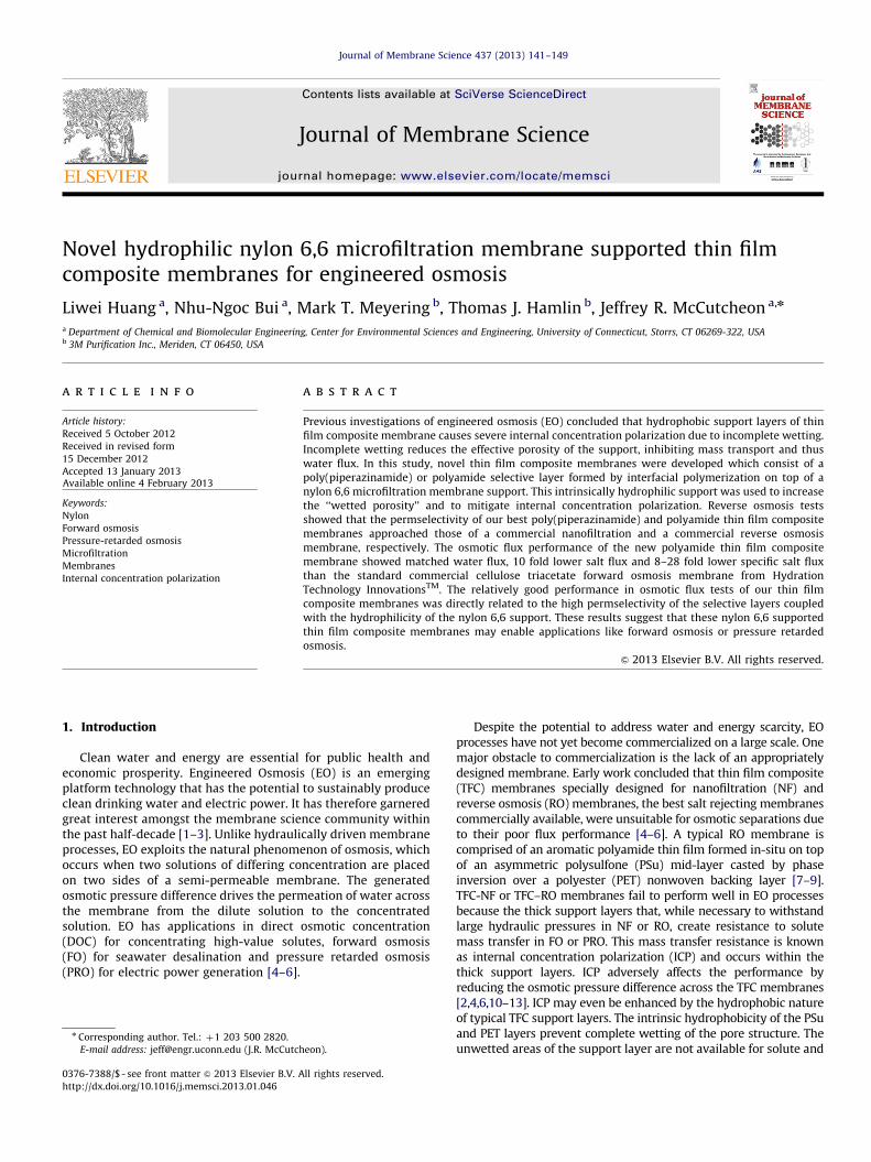
The surface and cross-sectional SEM images of nylon 6,6MFsupport are shown in Fig. 1. Both the surface of small-pore regionand large-pore region show rough and open porous morphology.The surface porosities of two zones are 51.1% and 48.4%, respec-tively. The average thickness of the support was measured to be181.471.1 mm and the contact angle of the support is approxi-mately 40.51, which is 40–501 lower than that of conventional TFCPSu support reported in other studies [32,33].
While these membranes are typically oriented with the largerpores facing the feed during MF, the selective layers of the TFCmembranes are built on the small pore size. The small poresregion allows for a selective layer to form with fewer defectswhile the large pores zone decreases the resistance to masstransfer. This finding is consistent with previous reports on TFCmembranes; membranes with a dense support layer resulted inhigh salt rejections yet low water fluxes [33,34].
3.2. Characterization and performance of poly(piperazinamide)
TFC membranes.
3.2.1. Top surface scanning electron micrographs
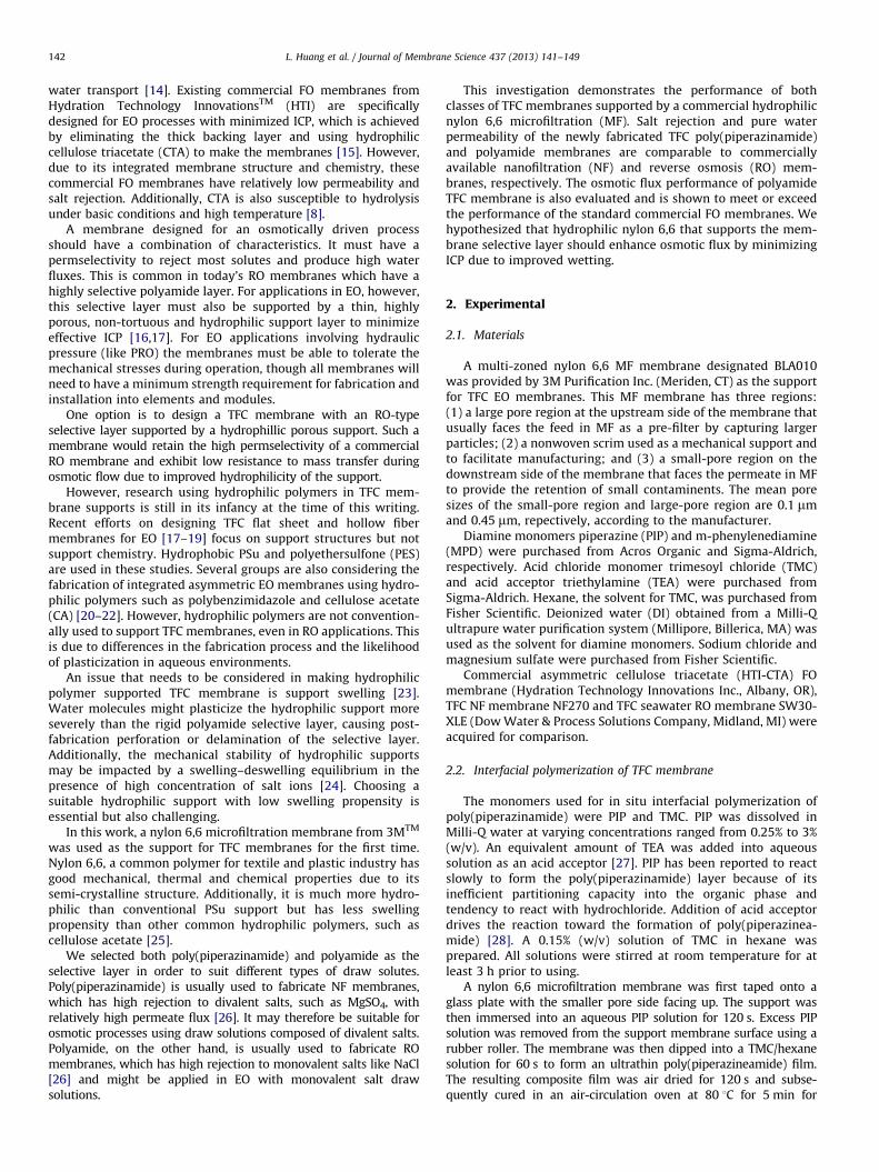
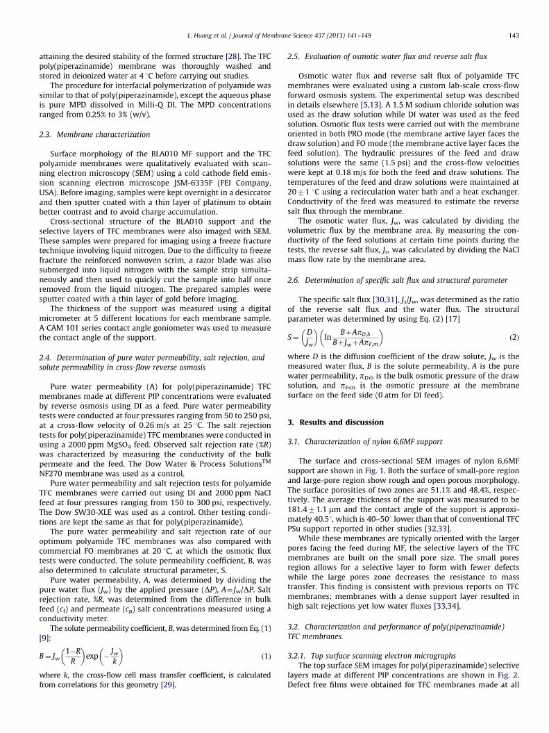
The top surface SEM images for poly(piperazinamide) selectivelayers made at different PIP concentrations are shown in Fig. 2.Defect free films were obtained for TFC membranes made at all
Fig. 2. Top surface SEM images (magnification 2200� ) of poly(piperazinamide) of TFC membranes made at PIP concentrations of (a) 0.25% (w/v); (b) 0.5%; (c) 1.0%;
(d) 2.0%; and (e) 3.0%; and of (f) commercial NF270.
Fig. 1. SEM images of (a) cross-section, (b) surface of small-pore region on which the selective layers were formed (magnification 5000� ), and (c) surface of large-pore
region of BLA010 nylon 6,6 support (magnification 5000� ).
L. Huang et al. / Journal of Membrane Science 437 (2013) 141–149144
PIP concentrations ranging from 0.25 to 3%. The surface morphol-ogy varied with PIP concentration. ‘‘Circle-like’’ morphologies canbe observed on 0.25% and 0.5% PIP based-TFC membranes, while amore uniform peak-and-valley structure appeared when using1.0% and 2.0% PIP. These peaks and valleys may be caused fromthe rough support layer as the lower PIP concentrations yieldthinner films. For 3.0% PIP based membrane, it seems that theselective layer entirely covered the features of the support andpeak-and-valley structure disappeared. Generally, our PIP basedTFC membranes gave rougher surfaces than commercial NF270.
3.2.2. Cross-sectional scanning electron micrographs
The cross-sectional SEM images for poly(piperazinamide) selectivelayers made at different PIP concentrations are shown in Fig. 3. Thecorresponding thickness as a function of PIP concentration is shownin Table 1. Ultra-thin poly(piperazinamide) layers with the thicknessless than 1 mm were obtained. The thickness of the selective layersfirst gradually increased with increasing PIP concentration up to 2%,and then dramatically increased to 0.9 mm at 3% PIP. It is alsoimportant to note that at 3% PIP, the poly(piperazinamide) selectivelayer seems to delaminate from the support. On the other hand, theresulting TFC selective layers made at lower PIP concentration (i.e.,less than 1%) were better integrated with the support, indicatingbetter adhesion with the support.
3.2.3. Reverse osmosis tests
Fig. 4 illustrates the MgSO4 rejection rates for PIP based TFCmembranes as a function of PIP concentration. The rejection rateincreased with increase in PIP concentration until 2% due toincreased density of the film, then unexpectedly drop at 3%. Thisdramatic performance drop for 3% PIP selective layer may be due
to the observed delamination of the selective layer in the SEMimages (Fig. 3). It is also seen that the rejection for 0.25% and 0.5%PIP based membranes decreased with increasing hydraulic pres-sure, indicating the resulting films became more flexible and/orweaker under higher pressures. However, the rejection rates of 1%and 2% PIP based TFC membranes maintained above 95% over arange of hydraulic pressures, which approached the rejectionperformance of NF270. The good pressure tolerance of our TFCmembranes also implies their potential application in pressureretarded osmosis.
Table 2 shows the pure water permeability of the PIP basedTFC membranes. The water permeability decreased with enhan-cing PIP concentration due to the increased thickness of theselective layer. Comparing with commercial NF270, our 1% PIPbased TFC membrane not only showed a similar rejection rate, butalso a matched water flux. Overall performance of our handmadeTFC membranes matched up that of a industry standard com-mercial NF membrane.
3.3. Characterization and performance of polyamide TFC
membranes.
3.3.1. Top surface scanning electron micrographs
The top surface SEM images for polyamide selective layersmade at different MPD concentrations are shown in Fig. 5. Defectfree films with ridge-and-valley structure were obtained for TFCmembranes made at all MPD concentrations ranging from 0.25 to3%. All of the selective layers of our TFC membranes appeared tobe rougher than commercial SW30-XLE membranes.
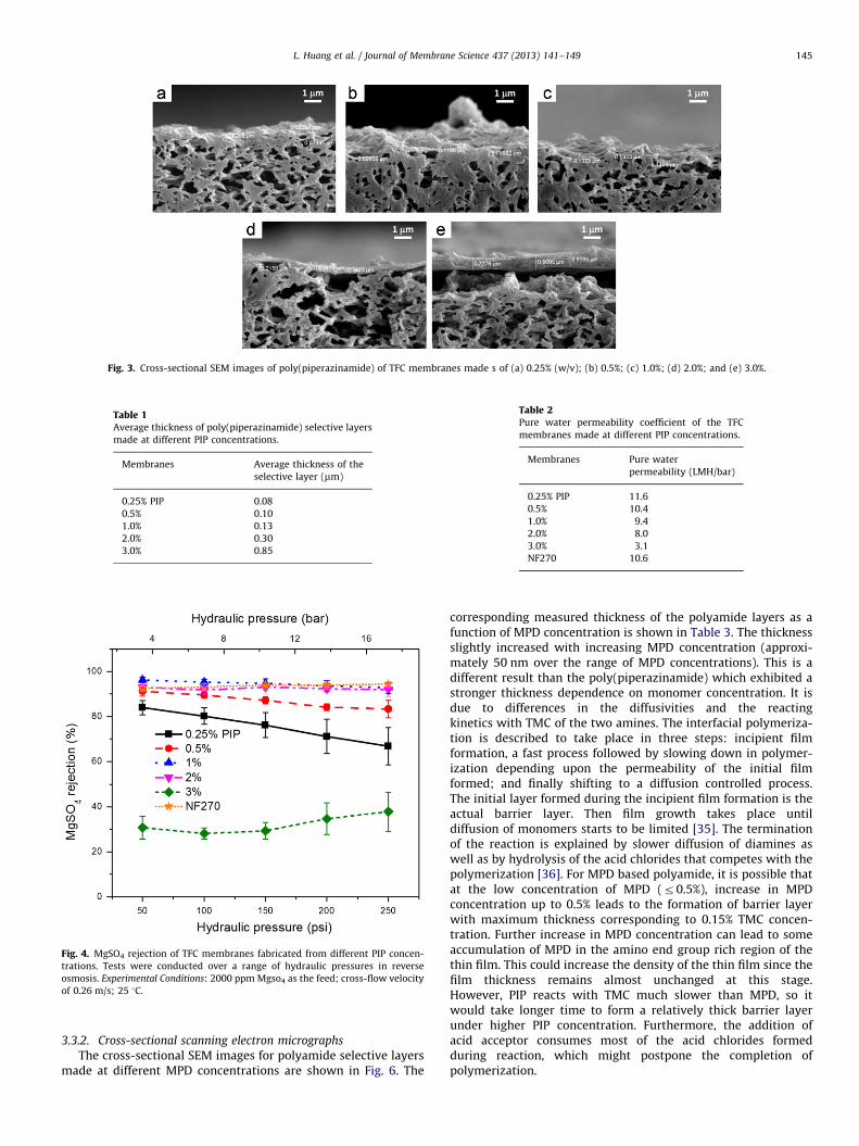
Fig. 3. Cross-sectional SEM images of poly(piperazinamide) of TFC membranes made s of (a) 0.25% (w/v); (b) 0.5%; (c) 1.0%; (d) 2.0%; and (e) 3.0%.
Table 1Average thickness of poly(piperazinamide) selective layers
made at different PIP concentrations.
Membranes Average thickness of the
selective layer (mm)
0.25% PIP 0.08
0.5% 0.10
1.0% 0.13
2.0% 0.30
3.0% 0.85
Fig. 4. MgSO4 rejection of TFC membranes fabricated from different PIP concen-
trations. Tests were conducted over a range of hydraulic pressures in reverse
osmosis. Experimental Conditions: 2000 ppm Mgso4 as the feed; cross-flow velocity
of 0.26 m/s; 25 1C.
Table 2Pure water permeability coefficient of the TFC
membranes made at different PIP concentrations.
Membranes Pure water
permeability (LMH/bar)
0.25% PIP 11.6
0.5% 10.4
1.0% 9.4
2.0% 8.0
3.0% 3.1
NF270 10.6
L. Huang et al. / Journal of Membrane Science 437 (2013) 141–149 145
3.3.2. Cross-sectional scanning electron micrographs
The cross-sectional SEM images for polyamide selective layersmade at different MPD concentrations are shown in Fig. 6. The
corresponding measured thickness of the polyamide layers as afunction of MPD concentration is shown in Table 3. The thicknessslightly increased with increasing MPD concentration (approxi-mately 50 nm over the range of MPD concentrations). This is adifferent result than the poly(piperazinamide) which exhibited astronger thickness dependence on monomer concentration. It isdue to differences in the diffusivities and the reactingkinetics with TMC of the two amines. The interfacial polymeriza-tion is described to take place in three steps: incipient filmformation, a fast process followed by slowing down in polymer-ization depending upon the permeability of the initial filmformed; and finally shifting to a diffusion controlled process.The initial layer formed during the incipient film formation is theactual barrier layer. Then film growth takes place untildiffusion of monomers starts to be limited [35]. The terminationof the reaction is explained by slower diffusion of diamines aswell as by hydrolysis of the acid chlorides that competes with thepolymerization [36]. For MPD based polyamide, it is possible thatat the low concentration of MPD (r0.5%), increase in MPDconcentration up to 0.5% leads to the formation of barrier layerwith maximum thickness corresponding to 0.15% TMC concen-tration. Further increase in MPD concentration can lead to someaccumulation of MPD in the amino end group rich region of thethin film. This could increase the density of the thin film since thefilm thickness remains almost unchanged at this stage.However, PIP reacts with TMC much slower than MPD, so itwould take longer time to form a relatively thick barrier layerunder higher PIP concentration. Furthermore, the addition ofacid acceptor consumes most of the acid chlorides formedduring reaction, which might postpone the completion ofpolymerization.
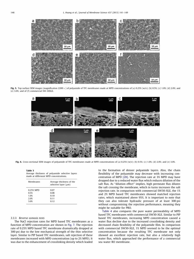
Fig. 5. Top surface SEM images (magnification 2200� ) of polyamide of TFC membranes made at MPD concentrations of (a) 0.25% (w/v); (b) 0.5%; (c) 1.0%; (d) 2.0%; and
(e) 3.0%; and of (f) commercial SW-30XLE.
Fig. 6. Cross-sectional SEM images of polyamide of TFC membranes made at MPD concentrations of (a) 0.25% (w/v); (b) 0.5%; (c) 1.0%; (d) 2.0%; and (e) 3.0%.
Table 3Average thickness of polyamide selective layers
made at differnent MPD concentrations.
Membranes Average thickness of the
selective layer (mm)
0.25% MPD 0.07
0.5% 0.08
1.0% 0.10
2.0% 0.11
3.0% 0.12
L. Huang et al. / Journal of Membrane Science 437 (2013) 141–149146
3.3.3. Reverse osmosis tests
The NaCl rejection rates for MPD based TFC membranes as afunction of MPD concentration are shown in Fig. 7. The rejectionrate of 0.25% MPD based TFC membrane dramatically dropped at300 psi due to the low mechanical strength of the thin selectivelayer. Similar to PIP based TFC membranes, salt rejection of thesemembranes increased with MPD concentration (up to 2% MPD). Itwas due to the enhancement of crosslinking density which leaded
to the formation of denser polyamide layers. Also, the chainflexibility of the polyamide may decrease with increasing con-centration of MPD [28]. The rejection rate at 3% MPD may havedropped due to a reduced water flux which reduces dilution of thesalt flux. As ‘‘dilution effect’’ implies, high permeate flux dilutesthe salt crossing the membrane, which in turns increases the saltrejection rate. In comparison with commercial SW30-XLE, the 1%and 2% MPD based TFC membranes showed matched rejectionrates, which maintained above 95%. It is important to note thatthey can also tolerate hydraulic pressure of at least 300 psiwithout compromising the rejection performance, meaning theymight be suitable for PRO.
Table 4 also compares the pure water permeability of MPDbased TFC membranes with commercial SW30-XLE. Similar to PIPbased TFC membranes, increasing MPD concentration caused awater flux decline due to the increased crosslinking density anddecreased chain flexibility of the polyamide film. In comparisonwith commercial SW30-XLE, 1% MPD seemed to be the optimalconcentration because the resulting TFC membrane not onlyshowed an excellent rejection rate, but also a relatively highwater flux, which approached the performance of a commercialsea water RO membrane.
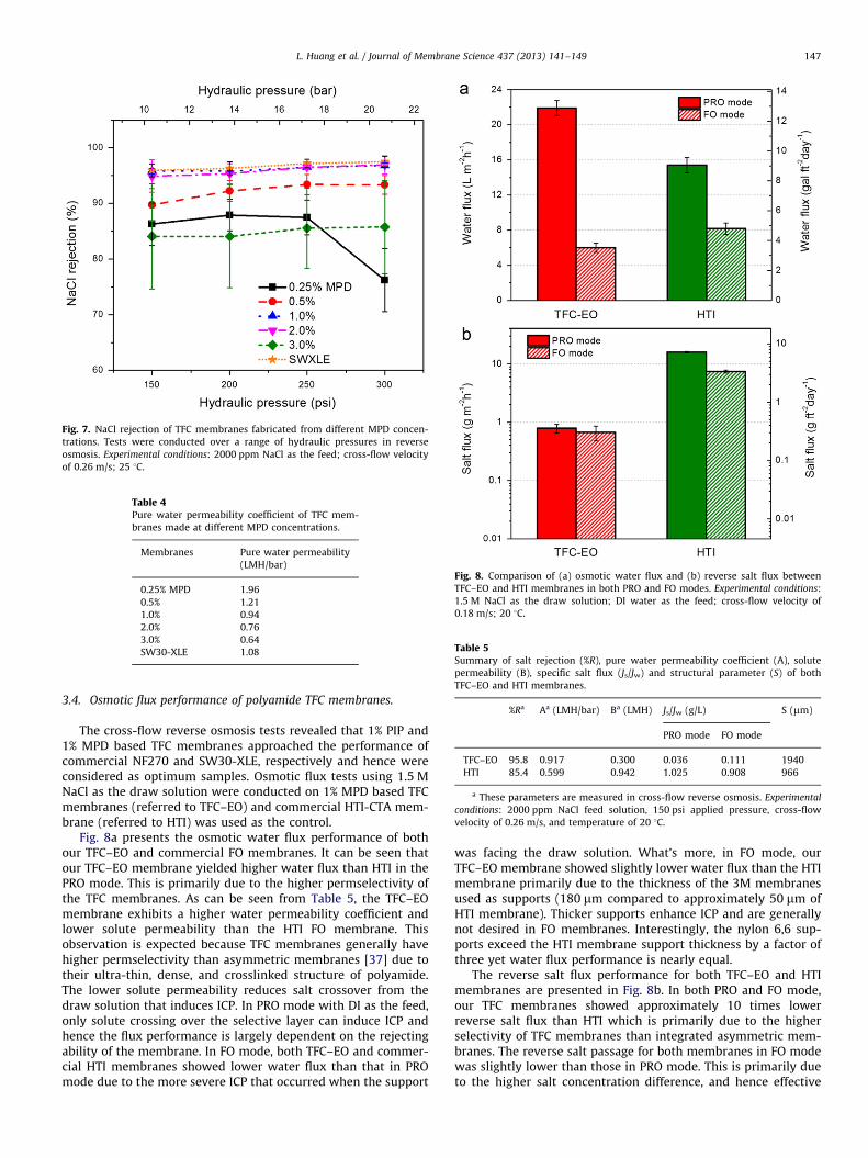
Fig. 7. NaCl rejection of TFC membranes fabricated from different MPD concen-
trations. Tests were conducted over a range of hydraulic pressures in reverse
osmosis. Experimental conditions: 2000 ppm NaCl as the feed; cross-flow velocity
of 0.26 m/s; 25 1C.
Table 4Pure water permeability coefficient of TFC mem-
branes made at different MPD concentrations.
Membranes Pure water permeability
(LMH/bar)
0.25% MPD 1.96
0.5% 1.21
1.0% 0.94
2.0% 0.76
3.0% 0.64
SW30-XLE 1.08
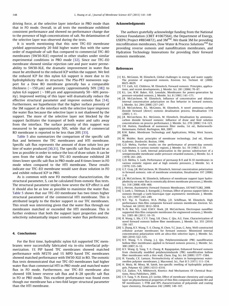
Fig. 8. Comparison of (a) osmotic water flux and (b) reverse salt flux between
TFC–EO and HTI membranes in both PRO and FO modes. Experimental conditions:
1.5 M NaCl as the draw solution; DI water as the feed; cross-flow velocity of
0.18 m/s; 20 1C.
Table 5Summary of salt rejection (%R), pure water permeability coefficient (A), solute
permeability (B), specific salt flux (Js/Jw) and structural parameter (S) of both
TFC–EO and HTI membranes.
%Ra Aa (LMH/bar) Ba (LMH) Js/Jw (g/L) S (mm)
PRO mode FO mode
TFC–EO 95.8 0.917 0.300 0.036 0.111 1940
HTI 85.4 0.599 0.942 1.025 0.908 966
a These parameters are measured in cross-flow reverse osmosis. Experimental
conditions: 2000 ppm NaCl feed solution, 150 psi applied pressure, cross-flow
velocity of 0.26 m/s, and temperature of 20 1C.
L. Huang et al. / Journal of Membrane Science 437 (2013) 141–149 147
3.4. Osmotic flux performance of polyamide TFC membranes.
The cross-flow reverse osmosis tests revealed that 1% PIP and1% MPD based TFC membranes approached the performance ofcommercial NF270 and SW30-XLE, respectively and hence wereconsidered as optimum samples. Osmotic flux tests using 1.5 MNaCl as the draw solution were conducted on 1% MPD based TFCmembranes (referred to TFC–EO) and commercial HTI-CTA mem-brane (referred to HTI) was used as the control.
Fig. 8a presents the osmotic water flux performance of bothour TFC–EO and commercial FO membranes. It can be seen thatour TFC–EO membrane yielded higher water flux than HTI in thePRO mode. This is primarily due to the higher permselectivity ofthe TFC membranes. As can be seen from Table 5, the TFC–EOmembrane exhibits a higher water permeability coefficient andlower solute permeability than the HTI FO membrane. Thisobservation is expected because TFC membranes generally havehigher permselectivity than asymmetric membranes [37] due totheir ultra-thin, dense, and crosslinked structure of polyamide.The lower solute permeability reduces salt crossover from thedraw solution that induces ICP. In PRO mode with DI as the feed,only solute crossing over the selective layer can induce ICP andhence the flux performance is largely dependent on the rejectingability of the membrane. In FO mode, both TFC–EO and commer-cial HTI membranes showed lower water flux than that in PROmode due to the more severe ICP that occurred when the support
was facing the draw solution. What’s more, in FO mode, ourTFC–EO membrane showed slightly lower water flux than the HTImembrane primarily due to the thickness of the 3M membranesused as supports (180 mm compared to approximately 50 mm ofHTI membrane). Thicker supports enhance ICP and are generallynot desired in FO membranes. Interestingly, the nylon 6,6 sup-ports exceed the HTI membrane support thickness by a factor ofthree yet water flux performance is nearly equal.
The reverse salt flux performance for both TFC–EO and HTImembranes are presented in Fig. 8b. In both PRO and FO mode,our TFC membranes showed approximately 10 times lowerreverse salt flux than HTI which is primarily due to the higherselectivity of TFC membranes than integrated asymmetric mem-branes. The reverse salt passage for both membranes in FO modewas slightly lower than those in PRO mode. This is primarily dueto the higher salt concentration difference, and hence effective
L. Huang et al. / Journal of Membrane Science 437 (2013) 141–149148
driving force, at the selective layer interface in PRO mode thanthat in FO mode. Overall, in all tests the membrane exhibitedconsistent performance and showed no performance change dueto the presence of high concentrations of salt. No delamination ofthe selective layer was observed during the tests.
It is worth mentioning that this new TFC–EO membraneyielded approximately 20 fold higher water flux with the sameorder of magnitude of salt flux compared to commercial TFC–ROmembranes (SW30-XLE) reported in other studies under similarexperimental conditions in PRO mode [32]. Since our TFC–EOmembrane showed similar rejection rate and pure water perme-ability to SW30-XLE, the dramatic improvement in water fluxmust be attributed to the reduced ICP within the support. We feelthe reduced ICP for this nylon 6,6 support is more due to itshydrohphilicity than its structure. The PSu-PET nonwoven sup-port for a Dow RO membrane generally has a comparablethickness (�150 mm) and porosity (approximately 50% [38]) tonylon 6,6 support (�180 mm and approximately 50�60% poros-ity). Improved wetting of this layer will dramatically reduce theeffective structural parameter and improve osmotic flux [14].Furthermore, we hypothesize that the higher surface porosity ofthe 3M support at the interface with the selective layer improvesthe water flux because the selective layer is not shadowed by thesupport. The more of the selective layer not blocked by thesupport facilitates the transport of both water and salts awayfrom the interface. The surface porosity of this support wasmeasured to be approximately 50%, while that of commercialRO membrane is reported to be less than 20% [33].
Table 5 also summarizes the comparison of the specific saltflux and between the TFC membranes and HTI membrane.Specific salt flux represents the amount of draw solute loss perliter of water produced [30,31]. The specific salt flux should be aslow as possible in order to reduce the loss of draw solute. It can beseen from the table that our TFC–EO membrane exhibited 28times lower specific salt flux in PRO mode and 8 times lower in FOmode when compared to the HTI membrane. These resultsindicate our TFC–EO membrane would save draw solution in FOand exhibit reduced ICP in PRO.
As is common with new FO membrane characterization, thestructural parameter, S, can be calculated from osmotic flux tests.The structural parameter implies how severe the ICP effect is andit should also be as low as possible to maximize the water flux.Table 5 shows that our TFC–EO membrane has two times higherstructural parameter of the commercial HTI membrane. This isattributed largely to the thicker support in our TFC membranes.This result was interesting given that the water flux through ourmembranes matched or exceeded the HTI membrane. This isfurther evidence that both the support layer properties and theselectivity substantially impact osmotic water flux performance.
4. Conclusions
For the first time, hydrophilic nylon 6,6 supported TFC mem-branes were successfully fabricated via in-situ interfacial poly-merization. 1% PIP based TFC membranes showed matchedperformance with NF270 and 1% MPD based TFC membranesshowed matched performance with SW30-XLE in RO. The osmoticflux tests demonstrated that our TFC–EO membranes had higherwater flux than commercial HTI in PRO mode and matched waterflux in FO mode. Furthermore, our TFC–EO membrane alsoshowed 10X lower reverse salt flux and 8–28 specific salt fluxin FO or PRO mode. This excellent performance was found eventhough our membrane has a two-fold larger structural parameterthan the HTI membrane.
Acknowledgments
The authors gratefully acknowledge funding from the NationalScience Foundation (CBET #1067564), the Department of Energy,USEPA (Project #R834872), and 3MTM. We thank 3M for providingmicrofiltration membranes, Dow Water & Process SolutionsTM forproviding reverse osmosis and nanofiltration membranes, andHydration Technology Innovations for providing their forwardosmosis membrane.
References
[1] R.L. McGinnis, M. Elimelech, Global challenges in energy and water supply:The promise of engineered osmosis, Environ. Sci. Technol. 42 (2008)8625–8629.
[2] T.Y. Cath, A.E. Childress, M. Elimelech, Forward osmosis: Principles, applica-tions, and recent developments, J. Membr. Sci. 281 (2006) 70–87.
[3] K.L. Lee, R.W. Baker, H.K. Lonsdale, Membranes for power-generation bypressure-retarded osmosis, J. Membr. Sci. 8 (1981) 141–171.
[4] J.R. McCutcheon, M. Elimelech, Influence of concentrative and dilutiveinternal concentration polarization on flux behavior in forward osmosis,J. Membr. Sci. 284 (2006) 237–247.
[5] J.R. McCutcheon, R.L. McGinnis, M. Elimelech, A novel ammonia–carbondioxide forward (direct) osmosis desalination process, Desalination 174(2005) 1–11.
[6] J.R. McCutcheon, R.L. McGinnis, M. Elimelech, Desalination by ammonia–carbon dioxide forward osmosis: Influence of draw and feed solutionconcentrations on process performance, J. Membr. Sci. 278 (2006) 114–123.
[7] I.M. Hutten, Handbook of nonwoven filter media, 1st ed., Butterworth-Heinemann, Oxford; Burlington, MA, 2007.
[8] R.W. Baker, Membrane Technology and Applications, Wiley, West Sussex,2004.
[9] M. Mulder, Basic principles of membrane technology, 2nd ed., KluwerAcademic, Dordrecht; Boston, 1996.
[10] G.D. Mehta, Further results on the performance of present-day osmoticmembranes in various osmotic regions, J. Membr. Sci. 10 (1982) 3–19.
[11] G.D. Mehta, S. Loeb, Internal polarization in the porous substructure of asemipermeable membrane under pressure-retarded osmosis, J. Membr. Sci. 4(1978) 261–265.
[12] G.D. Mehta, S. Loeb, Performance of permasep B-9 and B-10 membranes invarious osmotic regions and at high osmotic pressures, J. Membr. Sci. 4(1979) 335–349.
[13] G.T. Gray, J.R. McCutcheon, M. Elimelech, Internal concentration polarizationin forward osmosis: role of membrane orientation, Desalination 197 (2006)1–8.
[14] J.R. McCutcheon, M. Elimelech, Influence of membrane support layer hydro-phobicity on water flux in osmotically driven membrane processes, J. Membr.Sci. 318 (2008) 458–466.
[15] J. Herron, Asymmetric Forward Osmosis Membranes, US7445712B2, 2008.[16] S. Loeb, L. Titelman, E. Korngold, J. Freiman, Effect of porous support fabric on
osmosis through a Loeb-Sourirajan type asymmetric membrane, J. Membr.Sci. 129 (1997) 243–249.
[17] N.Y. Yip, A. Tiraferri, W.A. Phillip, J.D. Schiffman, M. Elimelech, Highperformance thin-film composite forward osmosis membrane, Environ. Sci.Technol. 44 (2010) 3812–3818.
[18] N.-N. Bui, M.L. Lind, E.M.V. Hoek, J.R. McCutcheon, Electrospun nanofibersupported thin film composite membranes for engineered osmosis, J. Membr.Sci. 3385–86 (2011) 10–19.
[19] R. Wang, L. Shi, C.Y.Y. Tang, S.R. Chou, C. Qiu, A.G. Fane, Characterization ofnovel forward osmosis hollow fiber membranes, J. Membr. Sci. 355 (2010)158–167.
[20] S. Zhang, K.Y. Wang, T.-S. Chung, H. Chen, Y.C. Jean, G. Amy, Well-constructedcellulose acetate membranes for forward osmosis: Minimized internalconcentration polarization with an ultra-thin selective layer, J. Membr. Sci.360 (2010) 522–535.
[21] K.Y. Wang, T.-S. Chung, J.-J. Qin, Polybenzimidazole (PBI) nanofiltrationhollow fiber membranes applied in forward osmosis process, J. Membr. Sci.300 (2007) 6–12.
[22] K.Y. Wang, Q. Yang, T.-S. Chung, R. Rajagopalan, Enhanced forward osmosisfrom chemically modified polybenzimidazole (PBI) nanofiltration hollowfiber membranes with a thin wall, Chem. Eng. Sci. 64 (2009) 1577–1584.
[23] H. Yasuda, C.E. Lamaze, Permselectivity of solutes in homogeneous water-swollen polymer membranes, J. Macromol. Sci., Part B 5 (1971) 111–134.
[24] H. Muta, M. Miwa, M. Satoh, Ion-specific swelling of hydrophilic polymergels, Polymer 42 (2001) 6313–6316.
[25] G.E. Zaikov, Y.A. Mikheevch, Kinetics And Mechanisms Of Chemical Reac-tions, Nova Publishers, 2005.
[26] C.Y. Tang, Y.-N. Kwon, J.O. Leckie, Effect of membrane chemistry and coatinglayer on physiochemical properties of thin film composite polyamide RO andNF membranes: I. FTIR and XPS characterization of polyamide and coatinglayer chemistry, Desalination 242 (2009) 149–167.
L. Huang et al. / Journal of Membrane Science 437 (2013) 141–149 149
[27] L. Yung, H. Ma, X. Wang, K. Yoon, R. Wang, B.S. Hsiao, B. Chu, Fabrication ofthin-film nanofibrous composite membranes by interfacial polymerizationusing ionic liquids as additives, J. Membr. Sci. 365 (2010) 52–58.
[28] N.K. Saha, S.V. Joshi, Performance evaluation of thin film composite poly-amide nanofiltration membrane with variation in monomer type, J. Membr.Sci. 342 (2009) 60–69.
[29] E.M.V. Hoek, A.S. Kim, M. Elimelech, Influence of crossflow membrane filtergeometry and shear rate on colloidal fouling in reverse osmosis andnanofiltration separations, Environ. Eng. Sci. 19 (2002) 357–372.
[30] W.A. Phillip, J.S. Yong, M. Elimelech, Reverse Draw Solute Permeation inForward Osmosis: Modeling and Experiments, Environ. Sci. Technol. 44(2010) 5170–5176.
[31] N.T. Hancock, T.Y. Cath, Solute coupled diffusion in osmotically drivenmembrane processes, Environ. Sci. Technol. 43 (2009) 6769–6775.
[32] J.T. Arena, B. McCloskey, B.D. Freeman, J.R. McCutcheon, Surface modificationof thin film composite membrane support layers with polydopamine:Enabling use of reverse osmosis membranes in pressure retarded osmosis,J. Membr. Sci. 375 (2011) 55–62.
[33] A.K. Ghosh, E.M.V. Hoek, Impacts of support membrane structure andchemistry on polyamide–polysulfone interfacial composite membranes, J.Membr. Sci. 336 (2009) 140–148.
[34] P.S. Singh, S.V. Joshi, J.J. Trivedi, C.V. Devmurari, A.P. Rao, P.K. Ghosh, Probingthe structural variations of thin film composite RO membranes obtained by
coating polyamide over polysulfone membranes of different pore dimen-sions, J. Membr. Sci. 278 (2006) 19–25.
[35] R. Nadler, S. Srebnik, Molecular simulation of polyamide synthesis byinterfacial polymerization, J. Membr. Sci. 315 (2008) 100–105.
[36] V. Enkelmann, G. Wegner, Mechanism of interfacial polycondensation and
the direct synthesis of stable polyamide membranes, Die MakromolekulareChemie 177 (1976) 3177–3189.
[37] R.J. Petersen, Composite reverse-osmosis and nanofiltration membranes, J.Membr. Sci. 83 (1993) 81–150.
[38] J. Wei, C. Qiu, C.Y. Tang, R. Wang, A.G. Fane, Synthesis and characterization offlat-sheet thin film composite forward osmosis membranes, J. Membr. Sci.
372 (2011) 292–302.