ixblue positioning solutions - stf.ucsd.edustf.ucsd.edu/presentations/2015/2015-04 - ixblue...
TRANSCRIPT
iXBlue Positioning Solutionsyour data deserves the best positioning
August 2014
Aug 22nd , 2014
www.ixsea.com G_ST_TSH_043a Page 2 of 62Global Subsea Positioning Solutions
Table of content
Table of content ....................................................................................................................................................... 21. IXBLUE Brief Corporate Description ................................................................................................................. 4
1.1. Business Model..........................................................................................................................................41.2. iXBlue products development strategy .....................................................................................................5
1.2.1. iXBlue owns / masters the technologies................................................................................................ 51.2.2. iXBlue develops innovative solutions.....................................................................................................51.2.3. iXBlue equipment interfaces to other third-party systems ...................................................................61.2.4. Simple, unified interface........................................................................................................................61.2.5. Performance ..........................................................................................................................................7
1.3. Global Locations ........................................................................................................................................72. Scope of the document .................................................................................................................................... 83. Underwater positioning general considerations .............................................................................................. 9
3.1. Forewords: existing positioning technologies, their benefits and limits ...................................................93.2. Data Fusion and technologies combination ............................................................................................10
3.2.1. General principles ................................................................................................................................ 103.2.2. Examples 1: INS + GPS..........................................................................................................................103.2.3. Examples 2: INS + DVL, 4 hours survey ................................................................................................ 113.2.4. Examples 3: INS + USBL........................................................................................................................12
3.3. The “building blocks” concept .................................................................................................................123.4. Typical system configuration ...................................................................................................................143.5. USBL: Low frequency vs. medium frequency ..........................................................................................16
4. A review of iXBlue main positioning “building blocks”................................................................................... 174.1. PHINS 6000 INS Inertial Navigation System............................................................................................. 17
4.1.1. Positioning method.............................................................................................................................. 174.1.2. PHINS DVL Ready option......................................................................................................................184.1.3. PHINS general specifications................................................................................................................18
4.2. RAMSES – Synthetic Acoustic BaseLine Positoning System.....................................................................194.2.1. Sparse array navigation .......................................................................................................................194.2.2. On-the-fly calibration...........................................................................................................................204.2.3. Using already calibrated reference beacons........................................................................................204.2.4. RAMSES construction:..........................................................................................................................204.2.5. RAMSES general specifications: ...........................................................................................................21
4.3. POSIDONIA II extreme long range USBL system ......................................................................................224.3.1. POSIDONIA Acoustic Array (Antenna)..................................................................................................224.3.2. Main processing & command / control unit: .......................................................................................264.3.3. POSIDONIA II general specifications ....................................................................................................26
4.4. GAPS, combined INS+USBL pre-calibrated USBL system.........................................................................284.4.1. GAPS compared to standard USBL.......................................................................................................284.4.2. GAPS-NG new product generation ......................................................................................................294.4.3. GAPS-NG example of installation.........................................................................................................294.4.4. GAPS-NG general specifications...........................................................................................................30
4.5. OCEANO Transponders............................................................................................................................324.5.1. Recommended LF transponder for POSIDONIA II and RAMSES 6000..................................................334.5.2. Recommended transponder for GAPS-NG and RAMSES .....................................................................34
4.6. Software and firmware............................................................................................................................364.6.1. iXBlue unified WEB-based MMI (Man Machine Interface) ..................................................................364.6.2. DELPH RoadMap display software .......................................................................................................374.6.3. Data post-processing tool: DELPH INS, DELPH RAMSES, USBL Replay.................................................38
5. A scalable configuration for all kind of positioning requirements .................................................................. 40
Aug 22nd , 2014
www.ixsea.com G_ST_TSH_043a Page 3 of 62Global Subsea Positioning Solutions
5.1. Recommended configuration for a full solution......................................................................................405.2. Example of a complete POSIDONIA II USBL based solution ....................................................................44
5.2.1. POSIDONIA II alone features and benefits...........................................................................................445.2.2. POSIDONIA II used for Dynamic Positioning ........................................................................................465.2.3. POSIDONIA II (USBL) and PHINS/DVL...................................................................................................475.2.4. Sparse Array navigation: PHINS, USBL, RAMSES..................................................................................48
6. Specification and performance ...................................................................................................................... 516.1. Relative vs. absolute positioning .............................................................................................................516.2. Performance estimate (simulation).........................................................................................................51
6.2.1. Initial conditions ..................................................................................................................................516.2.2. Simulated trajectory and sensors available .........................................................................................516.2.3. ROVINS + pressure sensor simulation results ......................................................................................526.2.4. ROVINS + pressure sensor + DVL simulation results ............................................................................526.2.5. ROVINS + pressure sensor + DVL + USBL simulation results ................................................................ 536.2.6. ROVINS + pressure sensor + DVL + USBL + ROVINS simulation results................................................536.2.7. conclusion ............................................................................................................................................54
7. Benefits, References ...................................................................................................................................... 557.1. Advantages of the proposed solution .....................................................................................................557.2. User track records ...................................................................................................................................567.3. Installation Examples of IXBLUE Equipment Applications .......................................................................58
7.3.1. Dredging and Fall pipe ROV vessels .....................................................................................................587.3.2. Testimonial 1 - Multibeam survey .......................................................................................................587.3.3. Testimonial 2 – Metrology SAIPEM......................................................................................................607.3.4. Testimonial 3 – IFREMER Complete positioning system......................................................................60
Aug 22nd , 2014
www.ixsea.com G_ST_TSH_043a Page 4 of 62Global Subsea Positioning Solutions
1. IXBLUE Brief Corporate Description
iXBlue is a privately owned French technology company incorporating a wide range of capabilities to deliver worldleading solutions to the marine, land, air and space markets.
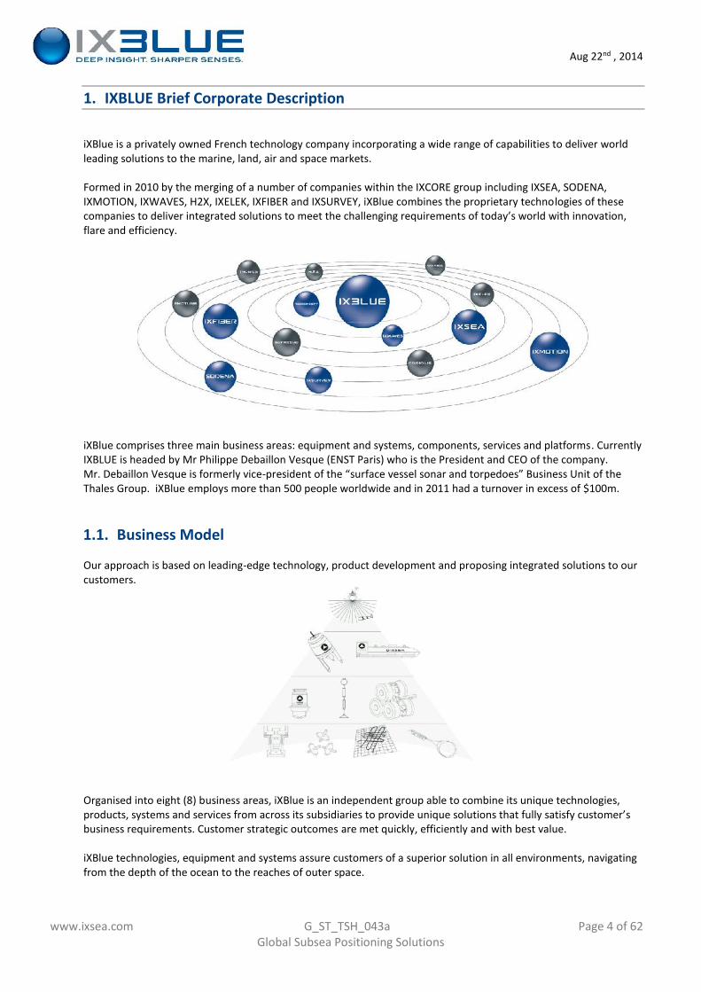
Formed in 2010 by the merging of a number of companies within the IXCORE group including IXSEA, SODENA,IXMOTION, IXWAVES, H2X, IXELEK, IXFIBER and IXSURVEY, iXBlue combines the proprietary technologies of thesecompanies to deliver integrated solutions to meet the challenging requirements of today’s world with innovation,flare and efficiency.
iXBlue comprises three main business areas: equipment and systems, components, services and platforms. CurrentlyIXBLUE is headed by Mr Philippe Debaillon Vesque (ENST Paris) who is the President and CEO of the company.Mr. Debaillon Vesque is formerly vice-president of the “surface vessel sonar and torpedoes” Business Unit of theThales Group. iXBlue employs more than 500 people worldwide and in 2011 had a turnover in excess of $100m.
1.1. Business Model
Our approach is based on leading-edge technology, product development and proposing integrated solutions to ourcustomers.
Organised into eight (8) business areas, iXBlue is an independent group able to combine its unique technologies,products, systems and services from across its subsidiaries to provide unique solutions that fully satisfy customer’sbusiness requirements. Customer strategic outcomes are met quickly, efficiently and with best value.
iXBlue technologies, equipment and systems assure customers of a superior solution in all environments, navigatingfrom the depth of the ocean to the reaches of outer space.
Aug 22nd , 2014
www.ixsea.com G_ST_TSH_043a Page 5 of 62Global Subsea Positioning Solutions
iXBlue consists of eight divisions in the following fields, with mainly IPD, APD and SOD (see below) divisions directlyinvolved in the underwater acoustic and or inertial positioning :
IPD: Inertial products (gyroscopes, accelerometers, INS)APD: Acoustic products (underwater navigation & positioning, beacons, pingers etc):SOD: Sea operations (survey)MSD: Motion systems (turrets)ISD: Integrated solutions (Intergrated Bridge,cartography)SSD: Sonar systems (sonars, seismic imaging systems)ACD: Advanced components (optical fibre)MWD: Marine works (ship building and refit)
1.2. iXBlue products development strategy
From day one and company incorporation iXBlue is having development guidelines which helped to design attractiveand innovative products and solutions.
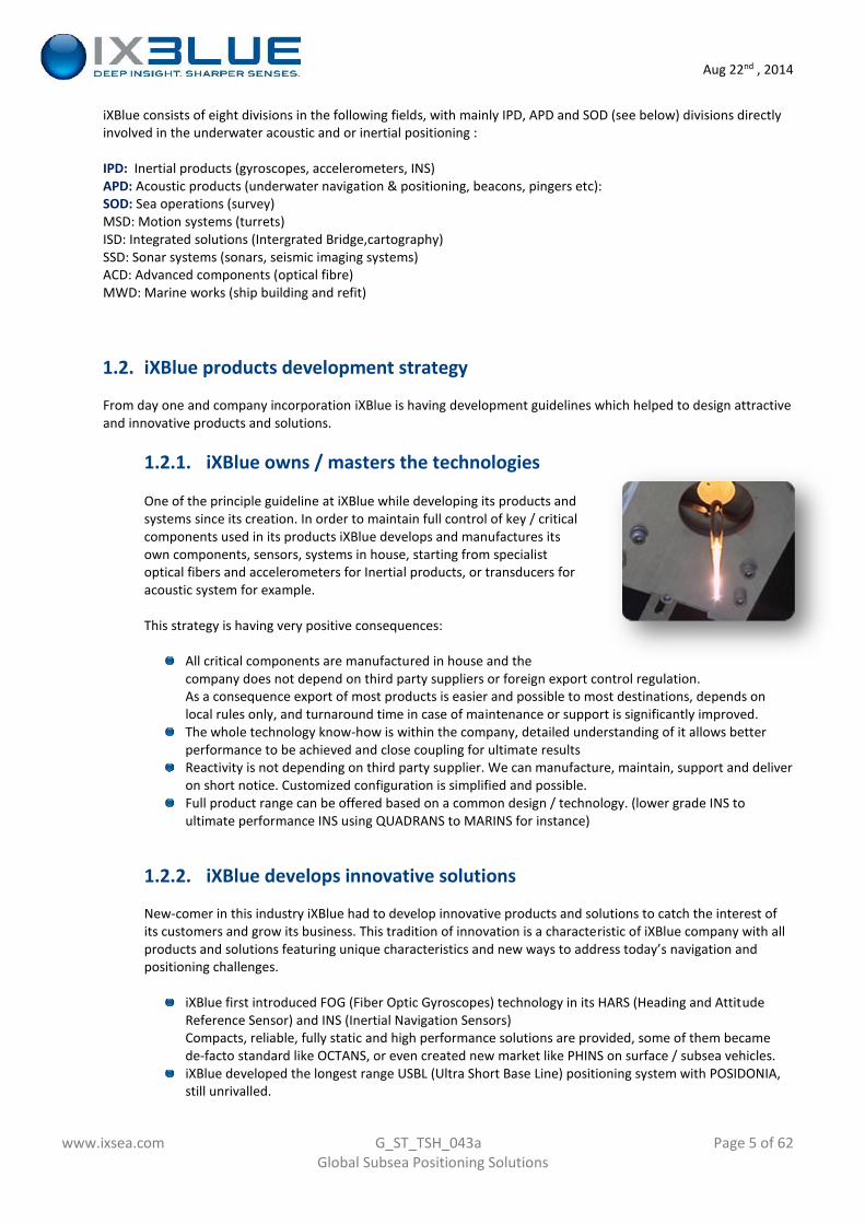
1.2.1. iXBlue owns / masters the technologies
One of the principle guideline at iXBlue while developing its products andsystems since its creation. In order to maintain full control of key / criticalcomponents used in its products iXBlue develops and manufactures itsown components, sensors, systems in house, starting from specialistoptical fibers and accelerometers for Inertial products, or transducers foracoustic system for example.
This strategy is having very positive consequences:
All critical components are manufactured in house and thecompany does not depend on third party suppliers or foreign export control regulation.As a consequence export of most products is easier and possible to most destinations, depends onlocal rules only, and turnaround time in case of maintenance or support is significantly improved.The whole technology know-how is within the company, detailed understanding of it allows betterperformance to be achieved and close coupling for ultimate resultsReactivity is not depending on third party supplier. We can manufacture, maintain, support and deliveron short notice. Customized configuration is simplified and possible.Full product range can be offered based on a common design / technology. (lower grade INS toultimate performance INS using QUADRANS to MARINS for instance)
1.2.2. iXBlue develops innovative solutions
New-comer in this industry iXBlue had to develop innovative products and solutions to catch the interest ofits customers and grow its business. This tradition of innovation is a characteristic of iXBlue company with allproducts and solutions featuring unique characteristics and new ways to address today’s navigation andpositioning challenges.
iXBlue first introduced FOG (Fiber Optic Gyroscopes) technology in its HARS (Heading and AttitudeReference Sensor) and INS (Inertial Navigation Sensors)Compacts, reliable, fully static and high performance solutions are provided, some of them becamede-facto standard like OCTANS, or even created new market like PHINS on surface / subsea vehicles.iXBlue developed the longest range USBL (Ultra Short Base Line) positioning system with POSIDONIA,still unrivalled.
Aug 22nd , 2014
www.ixsea.com G_ST_TSH_043a Page 6 of 62Global Subsea Positioning Solutions
GAPS, the first system combining acoustics, Inertial and GPS in a single pre-calibrated solution was arevolution in this activity thanks to its featuers and performance (pre-calibrated, compact and small,able to operate in all and most difficult conditions)RAMSES, latest building block in iXBlue positioning system is the first Synthetic Acoustic Baselinepositioning system, to replace ageing LBL (Long Base Line) solutions with no compromise onperformance and ease of operation.
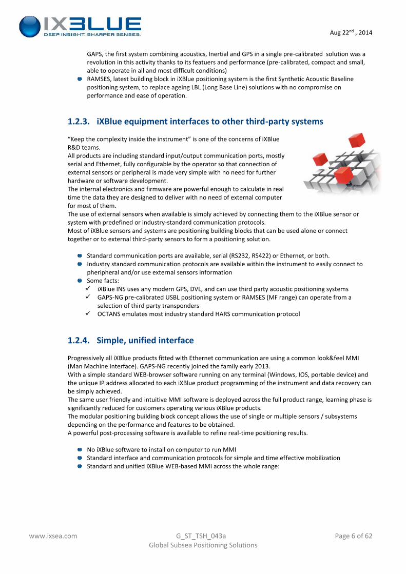
1.2.3. iXBlue equipment interfaces to other third-party systems
“Keep the complexity inside the instrument” is one of the concerns of iXBlueR&D teams.All products are including standard input/output communication ports, mostlyserial and Ethernet, fully configurable by the operator so that connection ofexternal sensors or peripheral is made very simple with no need for furtherhardware or software development.The internal electronics and firmware are powerful enough to calculate in realtime the data they are designed to deliver with no need of external computerfor most of them.The use of external sensors when available is simply achieved by connecting them to the iXBlue sensor orsystem with predefined or industry-standard communication protocols.Most of iXBlue sensors and systems are positioning building blocks that can be used alone or connecttogether or to external third-party sensors to form a positioning solution.
Standard communication ports are available, serial (RS232, RS422) or Ethernet, or both.Industry standard communication protocols are available within the instrument to easily connect topheripheral and/or use external sensors informationSome facts: iXBlue INS uses any modern GPS, DVL, and can use third party acoustic positioning systems GAPS-NG pre-calibrated USBL positioning system or RAMSES (MF range) can operate from a
selection of third party transponders OCTANS emulates most industry standard HARS communication protocol
1.2.4. Simple, unified interface
Progressively all iXBlue products fitted with Ethernet communication are using a common look&feel MMI(Man Machine Interface). GAPS-NG recently joined the family early 2013.With a simple standard WEB-browser software running on any terminal (Windows, IOS, portable device) andthe unique IP address allocated to each iXBlue product programming of the instrument and data recovery canbe simply achieved.The same user friendly and intuitive MMI software is deployed across the full product range, learning phase issignificantly reduced for customers operating various iXBlue products.The modular positioning building block concept allows the use of single or multiple sensors / subsystemsdepending on the performance and features to be obtained.A powerful post-processing software is available to refine real-time positioning results.
No iXBlue software to install on computer to run MMIStandard interface and communication protocols for simple and time effective mobilizationStandard and unified iXBlue WEB-based MMI across the whole range:
Aug 22nd , 2014
www.ixsea.com G_ST_TSH_043a Page 7 of 62Global Subsea Positioning Solutions
1.2.5. Performance
With core technology owned by the company and a large accumulated experience in navigation andpositioning system design and manufacturing iXBlue offers flexibility, modularity, and performance to hiscustomers.iXBlue pioneered the development of FOG based system with sophisticated and high performance data fusionalgorithm (OCTANS, PHINS, MARINS etc) and is a leader in combined inertial and acoustic technologiessolutions which are the only solutions able to provide robustness, redundancy and ultimate performance.The positioning building block principle allows the user to adapt his positioning solution to his projectsrequirements.
A long history of achievement and records:
POSIDONIA II USBL acoustic positioning system tracking up to 10kmGAPS pre-calibrated system working in mostadversed conditionsPHINS, a market standard, operating up to 85deg lat NorthComMet metrology solution providing 5cm accuracy and fastest operation timeMore than 3,000 OCTANS on the market become a generic name for Gyroscope
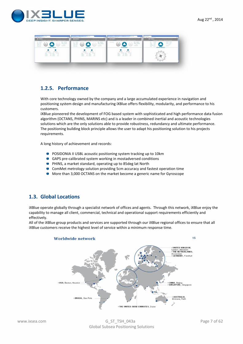
1.3. Global Locations
iXBlue operate globally through a specialist network of offices and agents. Through this network, iXBlue enjoy thecapability to manage all client, commercial, technical and operational support requirements efficiently andeffectively.All of the iXBlue group products and services are supported through our iXBlue regional offices to ensure that alliXBlue customers receive the highest level of service within a minimum response time.

Aug 22nd , 2014
www.ixsea.com G_ST_TSH_043a Page 8 of 62Global Subsea Positioning Solutions
2. Scope of the document
This page left blank intentionally
Aug 22nd , 2014
www.ixsea.com G_ST_TSH_043a Page 9 of 62Global Subsea Positioning Solutions
3. Underwater positioning general considerations
3.1. Forewords: existing positioning technologies, their benefits and limits
Positioning on the surface at sea has found its reference technology in GPS, a system that offers a straightforwardand inexpensive solution which has readily found a place in the daily routines of hydrographers, marine surveyorsand in maritime work in general.Unfortunately, solutions to the problem of subsea positioning are complicated by the fact that GPS radio signals donot penetrate water.
In the subsea environment, the available solutions are to use a positioning system based on the triangulation ofacoustic signals, (LBL, USBL, range measurement) or the use of Inertial Navigation Systems. All solutions haveinterest… and limitations:
a/ LBL positioning system (Long Base Line)
Mature (old?) technology which can lead to very high performance (operating frequency depending), LBLsystem is however long to mobilise and deploy since its principle is based on the acoustic communicationbetween a surface/embarked transceiver and an array of transponders (3 min) that must be deployed andcarefully calibrated.Moreover acoustic propagation depends on a number of external parameters (noise, maximum range, raybending) that can affect or in some extent prevent normal operations
b/ Conventional USBL positioning system (Ultra Short Base Line)
More recent on the market thanks to availability of powerful electronics and modern signal modulationand processing technics, USBL uses pure acoustic as well and the system correctly addresses some of theLBL limitations, …but brings some new drawbacks.Installation of USBL system is still a complex and time consuming task but it has to be done once only.Then one transponder on the target is required which makes the system quicker to deploy and with norestriction on the tracking area.The expected performance is lower than LBL systems, and in all circumstances USBL faces the samechallenges as LBL concerning acoustic propagation.
c/ Inertial Navigation Systems (INS)
One of the core business at iXBlue is about Inertial Systems based on proprietary FOG (Fiber OpticGyroscope). Using its internal sensors that monitor in real time motion and acceleration in three axis, anINS is able to update its initial position consequently and provide consistent position together with allattitude information (heading, pitch, roll, heave, speed, etc…)One can think we have here the ideal solution, but unfortunately and despite high performance /sophisticated software algorithm all INS drift along time and the calculated position will ultimately divergefrom the real one after a period of time. (Depending on the grade of the INS, from 1.3Nm/hour forROVINS to 1Nm/24h for MARINS, a military grade INS)
Aug 22nd , 2014
www.ixsea.com G_ST_TSH_043a Page 10 of 62Global Subsea Positioning Solutions
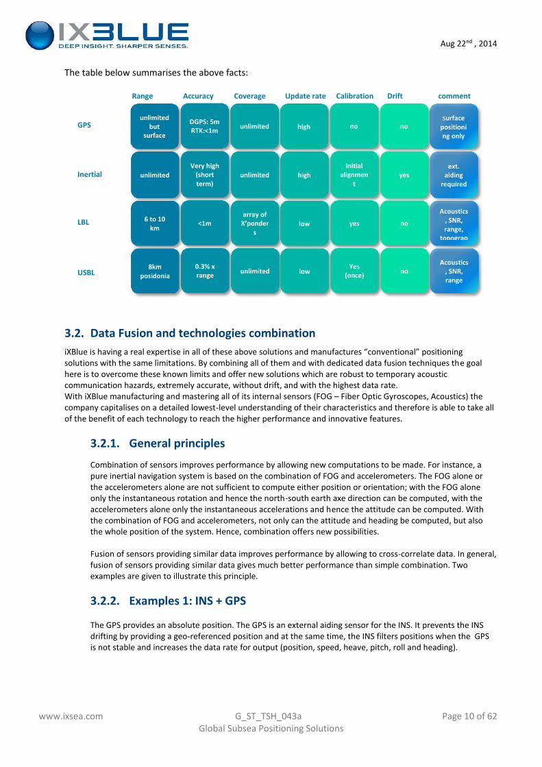
The table below summarises the above facts:
Range Accuracy Coverage Update rate Calibration Drift comment
GPS
Inertial
LBL
USBL
3.2. Data Fusion and technologies combinationiXBlue is having a real expertise in all of these above solutions and manufactures “conventional” positioningsolutions with the same limitations. By combining all of them and with dedicated data fusion techniques the goalhere is to overcome these known limits and offer new solutions which are robust to temporary acousticcommunication hazards, extremely accurate, without drift, and with the highest data rate.With iXBlue manufacturing and mastering all of its internal sensors (FOG – Fiber Optic Gyroscopes, Acoustics) thecompany capitalises on a detailed lowest-level understanding of their characteristics and therefore is able to take allof the benefit of each technology to reach the higher performance and innovative features.
3.2.1. General principles
Combination of sensors improves performance by allowing new computations to be made. For instance, apure inertial navigation system is based on the combination of FOG and accelerometers. The FOG alone orthe accelerometers alone are not sufficient to compute either position or orientation; with the FOG aloneonly the instantaneous rotation and hence the north-south earth axe direction can be computed, with theaccelerometers alone only the instantaneous accelerations and hence the attitude can be computed. Withthe combination of FOG and accelerometers, not only can the attitude and heading be computed, but alsothe whole position of the system. Hence, combination offers new possibilities.
Fusion of sensors providing similar data improves performance by allowing to cross-correlate data. In general,fusion of sensors providing similar data gives much better performance than simple combination. Twoexamples are given to illustrate this principle.
3.2.2. Examples 1: INS + GPS
The GPS provides an absolute position. The GPS is an external aiding sensor for the INS. It prevents the INSdrifting by providing a geo-referenced position and at the same time, the INS filters positions when the GPSis not stable and increases the data rate for output (position, speed, heave, pitch, roll and heading).
unlimitedbut
surface
DGPS: 5mRTK:<1m unlimited high no no
surfacepositioning only
unlimitedVery high
(shortterm)
unlimited highinitial
alignment
yesext.
aidingrequired
6 to 10km
<1marray of
X’ponders
low yes no
Acoustics, SNR,range,
topography
8kmposidonia
0.3% xrange unlimited low
Yes(once) no
Acoustics, SNR,range
Aug 22nd , 2014
www.ixsea.com G_ST_TSH_043a Page 11 of 62Global Subsea Positioning Solutions
Posit
ion
accu
racy
(m) ___
___
___
PHINS pure inertial drift(0.0002 x t²)Averaging of DGPS data(3/sqrt(t)PHINS+DGPS
Time (sec)
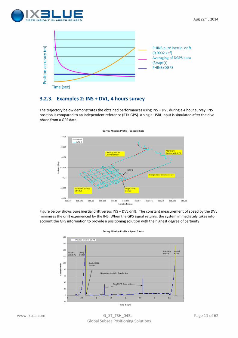
3.2.3. Examples 2: INS + DVL, 4 hours survey
The trajectory below demonstrates the obtained performances using INS + DVL during a 4 hour survey. INSposition is compared to an independent reference (RTK GPS). A single USBL input is simulated after the divephase from a GPS data.
Figure below shows pure inertial drift versus INS + DVL drift. The constant measurement of speed by the DVLminimises the drift experienced by the INS. When the GPS signal returns, the system immediately takes intoaccount the GPS information to provide a positioning solution with the highest degree of certainty
Survey Mission Profile - Speed 3 knts
48,36
48,365
48,37
48,375
48,38
48,385
48,39
355,54 355,545 355,55 355,555 355,56 355,565 355,57 355,575 355,58 355,585 355,59
Longitude (deg)
Latit
ude
(deg
)
PHINSDGPS
AlignmentSurface with GPS
Diving with no external sensor
Survey for 3 hourswith DVL
Single USBLUpdate
Climbing with noExternal sensor
DGPSlost
Survey Mission Profile - Speed 3 knts
-20
0
20
40
60
80
100
120
140
160
180
0 0,5 1 1,5 2 2,5 3 3,5 4
Time (hours)
Erro
r (m
eter
s)
Position error vs DGPS
Small GPS Drop out
ALGNwith GPS
DivingInertial
ClimbingInertial
Navigation Inertial + Doppler log
Inertial+GPS
Single USBLUpdate
Aug 22nd , 2014
www.ixsea.com G_ST_TSH_043a Page 12 of 62Global Subsea Positioning Solutions
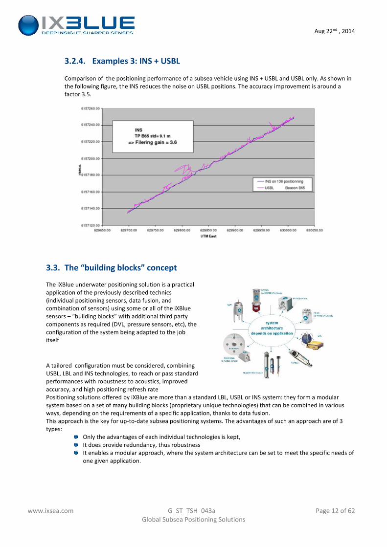
3.2.4. Examples 3: INS + USBL
Comparison of the positioning performance of a subsea vehicle using INS + USBL and USBL only. As shown inthe following figure, the INS reduces the noise on USBL positions. The accuracy improvement is around afactor 3.5.
3.3. The “building blocks” concept
The iXBlue underwater positioning solution is a practicalapplication of the previously described technics(individual positioning sensors, data fusion, andcombination of sensors) using some or all of the iXBluesensors – “building blocks” with additional third partycomponents as required (DVL, pressure sensors, etc), theconfiguration of the system being adapted to the jobitself
A tailored configuration must be considered, combiningUSBL, LBL and INS technologies, to reach or pass standardperformances with robustness to acoustics, improvedaccuracy, and high positioning refresh ratePositioning solutions offered by iXBlue are more than a standard LBL, USBL or INS system: they form a modularsystem based on a set of many building blocks (proprietary unique technologies) that can be combined in variousways, depending on the requirements of a specific application, thanks to data fusion.This approach is the key for up-to-date subsea positioning systems. The advantages of such an approach are of 3types:
Only the advantages of each individual technologies is kept,It does provide redundancy, thus robustnessIt enables a modular approach, where the system architecture can be set to meet the specific needs ofone given application.
Aug 22nd , 2014
www.ixsea.com G_ST_TSH_043a Page 13 of 62Global Subsea Positioning Solutions
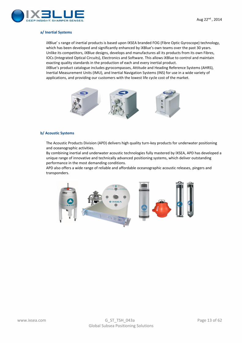
a/ Inertial Systems
iXBlue’ s range of inertial products is based upon IXSEA branded FOG (Fibre Optic Gyroscope) technology,which has been developed and significantly enhanced by iXBlue’s own teams over the past 30 years.Unlike its competitors, iXBlue designs, develops and manufactures all its products from its own Fibres,IOCs (Integrated Optical Circuits), Electronics and Software. This allows iXBlue to control and maintainexacting quality standards in the production of each and every inertial product.iXBlue‘s product catalogue includes gyrocompasses, Attitude and Heading Reference Systems (AHRS),Inertial Measurement Units (IMU), and Inertial Navigation Systems (INS) for use in a wide variety ofapplications, and providing our customers with the lowest life cycle cost of the market.
b/ Acoustic Systems
The Acoustic Products Division (APD) delivers high quality turn-key products for underwater positioningand oceanographic activities.By combining inertial and underwater acoustic technologies fully mastered by IXSEA, APD has developed aunique range of innovative and technically advanced positioning systems, which deliver outstandingperformance in the most demanding conditions.APD also offers a wide range of reliable and affordable oceanographic acoustic releases, pingers andtransponders.
Aug 22nd , 2014
www.ixsea.com G_ST_TSH_043a Page 14 of 62Global Subsea Positioning Solutions
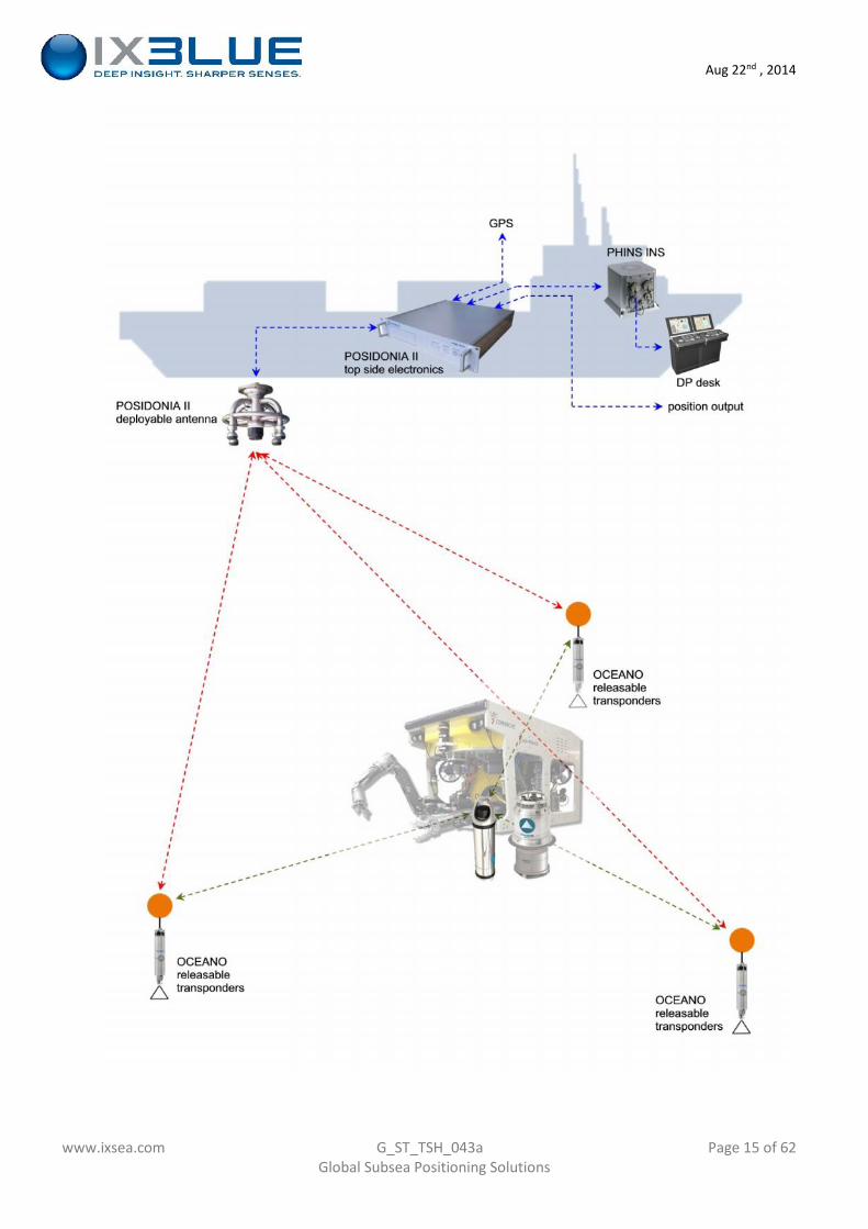
3.4. Typical system configuration
Although POSIDONIA Low Frequency/long range and PHINS are displayed below, alternative solutions using GAPS(medium frequency pre-calibrated USBL) and ROVINS can be considered as an option.Additional and optional sensors are also offered in order to further improve the performance of the global system.
The proposed solutions aims at providing:Up to LBL-grade positioning performance with only a few transponder deployed on sea bedSelf calibration of the seabed transponders (SLAM algorithm) while deploying the array and USBL(POSIDONIAII, or GAPS) / INS (PHINS or ROVINS)Sparse array capability, i.e. capacity to navigate with only a few reference beaconsRobust “station keeping” mode with L/USBL capability to interface to DP deskLong range and robust positioning with Low Frequency POSIDONIA II system
The core of such navigation system is the INS (PHINS or ROVINS) installed on the tracked vehicle. In order to containthe natural drift of the INS, external sensors are connected to it, each one having a specific advantage:
Pressure sensorINS is not as good in estimating its depth compared to horizontal position (X, Y). USBL is providing anestimate of the position with a 0.2% x range accuracy, which might not be sufficient. High qualitypressure sensor (Digiquartz or equivalent) will provide sub metric rough accuracy (0.01% x waterdepth) further improved after being processed by the INS Kalman filterDVLA Doppler Velocity log in bottom tracking mode (from 300 to 1200kHz) provides an accurate estimateof speed to the INS Kalman filter which is used to drastically reduce the INS drift.Compared to 0.6nM drift in free inertial mode (PHINS), the drift will be limited to 0.1% x travelleddistance with a well calibrated PHINS/DVL assembly.With a PHINS/DVL in bottom tracking mode a vehicule can navigate with less than 3m deviation / hourwhen travelling at 2knots in straight line.RAMSESWith slant distance to seabed transponder measured with a submetric – non-drifting – accuracyRAMSES is providing to PHINS a valuable reference to contain the system drift to almost zero. Ideally 2beacons are to be preferred so that PHINS/RAMSES will have a high quality reference along the twohorizontal axis.The correction will be applied every time beacons are in acoustic range to the vehicle, any residualdrift accumulated can be compensated for.USBL (POSIDONIA II or GAPS)The USBL provides an additional layer of redundancy by directly positioning the vehicle itself, andcontains the INS drift during the dive while DVL is not locked on sea bed yet, and seabed transpondersnot fully calibrated (SLAM algorithm in progress)
Aug 22nd , 2014
www.ixsea.com G_ST_TSH_043a Page 15 of 62Global Subsea Positioning Solutions
Aug 22nd , 2014
www.ixsea.com G_ST_TSH_043a Page 16 of 62Global Subsea Positioning Solutions
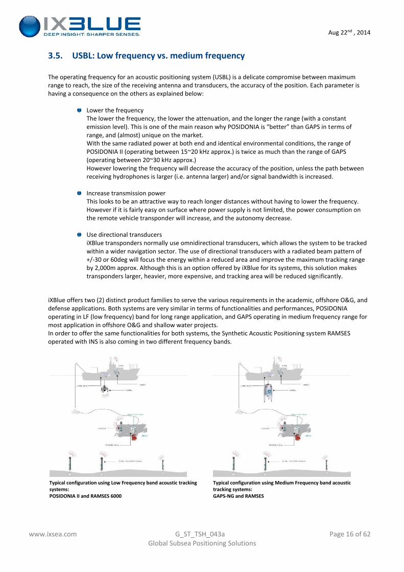
3.5. USBL: Low frequency vs. medium frequency
The operating frequency for an acoustic positioning system (USBL) is a delicate compromise between maximumrange to reach, the size of the receiving antenna and transducers, the accuracy of the position. Each parameter ishaving a consequence on the others as explained below:
Lower the frequencyThe lower the frequency, the lower the attenuation, and the longer the range (with a constantemission level). This is one of the main reason why POSIDONIA is “better” than GAPS in terms ofrange, and (almost) unique on the market.With the same radiated power at both end and identical environmental conditions, the range ofPOSIDONIA II (operating between 15~20 kHz approx.) is twice as much than the range of GAPS(operating between 20~30 kHz approx.)However lowering the frequency will decrease the accuracy of the position, unless the path betweenreceiving hydrophones is larger (i.e. antenna larger) and/or signal bandwidth is increased.
Increase transmission powerThis looks to be an attractive way to reach longer distances without having to lower the frequency.However if it is fairly easy on surface where power supply is not limited, the power consumption onthe remote vehicle transponder will increase, and the autonomy decrease.
Use directional transducersiXBlue transponders normally use omnidirectional transducers, which allows the system to be trackedwithin a wider navigation sector. The use of directional transducers with a radiated beam pattern of+/-30 or 60deg will focus the energy within a reduced area and improve the maximum tracking rangeby 2,000m approx. Although this is an option offered by iXBlue for its systems, this solution makestransponders larger, heavier, more expensive, and tracking area will be reduced significantly.
iXBlue offers two (2) distinct product families to serve the various requirements in the academic, offshore O&G, anddefense applications. Both systems are very similar in terms of functionalities and performances, POSIDONIAoperating in LF (low frequency) band for long range application, and GAPS operating in medium frequency range formost application in offshore O&G and shallow water projects.In order to offer the same functionalities for both systems, the Synthetic Acoustic Positioning system RAMSESoperated with INS is also coming in two different frequency bands.
Typical configuration using Low Frequency band acoustic trackingsystems:POSIDONIA II and RAMSES 6000
Typical configuration using Medium Frequency band acoustictracking systems:GAPS-NG and RAMSES
Aug 22nd , 2014
www.ixsea.com G_ST_TSH_043a Page 17 of 62Global Subsea Positioning Solutions
4. A review of iXBlue main positioning “building blocks”
The following pages comprise a brief introduction of the main iXBlue positioning building blocks and theircharacteristics when used as such. A separate technical description is available for each one on request, and thecombination of several or all of them into a global positioning solution is described in following chapters.
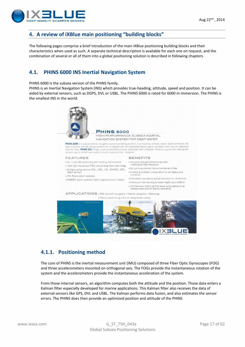
4.1. PHINS 6000 INS Inertial Navigation System
PHINS 6000 is the subsea version of the PHINS family.PHINS is an Inertial Navigation System (INS) which provides true-heading, attitude, speed and position. It can beaided by external sensors, such as DGPS, DVL or USBL. The PHINS 6000 is rated for 6000 m immersion. The PHINS isthe smallest INS in the world.
4.1.1. Positioning method
The core of PHINS is the inertial measurement unit (IMU) composed of three Fiber Optic Gyroscopes (FOG)and three accelerometers mounted on orthogonal axis. The FOGs provide the instantaneous rotation of thesystem and the accelerometers provide the instantaneous acceleration of the system.
From those internal sensors, an algorithm computes both the attitude and the position. Those data enters aKalman filter especially developed for marine applications. This Kalman filter also receives the data ofexternal sensors like GPS, DVL and USBL. The Kalman performs data fusion, and also estimates the sensorerrors. The PHINS does then provide an optimized position and attitude of the PHINS
Aug 22nd , 2014
www.ixsea.com G_ST_TSH_043a Page 18 of 62Global Subsea Positioning Solutions
4.1.2. PHINS DVL Ready option
PHINS 6000 can be provided with (or upgraded to) a DVL: this set is PHINS DVL ready. Theadvantage of using a DVL is that it provides system robustness and redundancy into thesystem, and that it reduces the drastically the drift of the PHINS when there is no regularposition input. Notably, this PHINS+DVL coupling is the state-of-the-art solution for AUVnavigation.Another specific advantage of the PHINS DVL ready is that the set is calibration free, so itavoids the difficult and costly alignment procedure that users have to perform each timethey install an INS and a DVL on a platform.
4.1.3. PHINS general specifications
a/ Gyrocompass and motion sensor
Mode Pure inertial GPS aiding USBL/LBL/DVLHeading x secant latitude (1)(2) 0.05 deg 0.01 deg 0.02 deg
Roll/Pitch (2) dynamic accuracy 0.01 deg 0.01 deg 0.01 deg
RangeHeading: 0 to 360°Roll: -180° to +180°Pitch: -90° to +90°
Heave, Surge, Sway 5 cm or 5%,whichever is higher
5 cm or 5%,whichever is higher
5 cm or 5%,whichever is higher
(1) Secant latitude = 1 / cosine latitude(2) RMS values. 68% of the data is within this value of confidence
b/ Inertial Navigation
Mode Pure inertial With GPS With USBL/LBL/DVL
Position (3)0.8 m after 1 mn3.2 m after 2 mn
0.6nm in 1h
3 times betterthan aidingsystem (4)
3 times betterthan aiding system (4)
0.1%of travelled distance
(3) CEP: Circular Error Probability. 50% of the data is within this value of confidence(4) Absolute position accuracy is dependent on aiding position sensor accuracy (i.e : GPS, USBL, LBL): PHINS 6000 will typically
improve accuracy by a factor 3 and reject position spikes to provide a smooth and high data rate navigation.
c/ Mechanical
PHINS 6000 PHINS 6000 DVL Ready
Dimensions (l x w x h) 255 mm x 288 mm 298 mm x 543 mm (WHN300/600)298 mm x 542 mm (WHN1200)
Weight air / water 23 kg / 13 kg
48.5 kg / 28.5 kg (WHN300/600K6)41.5 kg / 23.7 kg (WHN300/600K3)
43.7 kg / 27 kg (WHN1200K6)38.1 kg / 21 kg (WHN1200K3)
Construction Titanium TitaniumMounting Erreur ! Source du
renvoi introuvable.6 Φ 6.5 holes 6 Φ 11 holes
(5) Two alignment pin holes are provided under the base plate for accurate assembly/removal of PHINS 6000
Aug 22nd , 2014
www.ixsea.com G_ST_TSH_043a Page 19 of 62Global Subsea Positioning Solutions
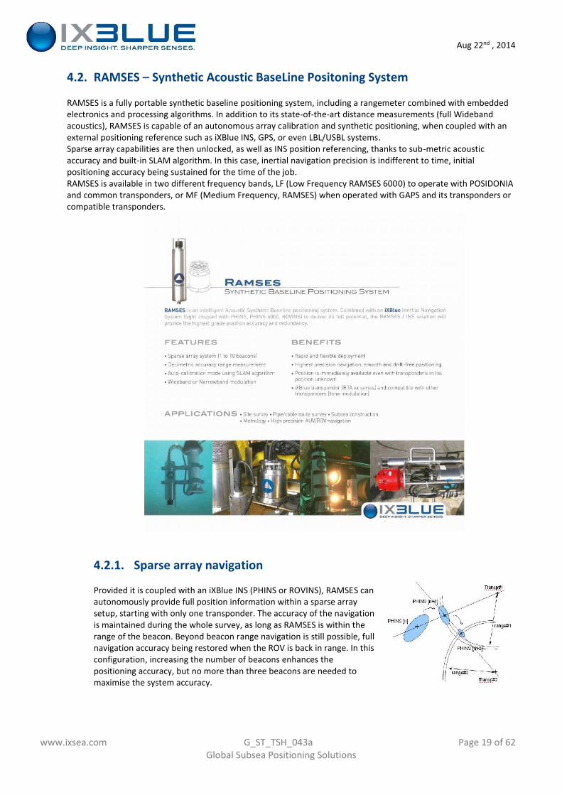
4.2. RAMSES – Synthetic Acoustic BaseLine Positoning System
RAMSES is a fully portable synthetic baseline positioning system, including a rangemeter combined with embeddedelectronics and processing algorithms. In addition to its state-of-the-art distance measurements (full Widebandacoustics), RAMSES is capable of an autonomous array calibration and synthetic positioning, when coupled with anexternal positioning reference such as iXBlue INS, GPS, or even LBL/USBL systems.Sparse array capabilities are then unlocked, as well as INS position referencing, thanks to sub-metric acousticaccuracy and built-in SLAM algorithm. In this case, inertial navigation precision is indifferent to time, initialpositioning accuracy being sustained for the time of the job.RAMSES is available in two different frequency bands, LF (Low Frequency RAMSES 6000) to operate with POSIDONIAand common transponders, or MF (Medium Frequency, RAMSES) when operated with GAPS and its transponders orcompatible transponders.
4.2.1. Sparse array navigation
Provided it is coupled with an iXBlue INS (PHINS or ROVINS), RAMSES canautonomously provide full position information within a sparse arraysetup, starting with only one transponder. The accuracy of the navigationis maintained during the whole survey, as long as RAMSES is within therange of the beacon. Beyond beacon range navigation is still possible, fullnavigation accuracy being restored when the ROV is back in range. In thisconfiguration, increasing the number of beacons enhances thepositioning accuracy, but no more than three beacons are needed tomaximise the system accuracy.
Aug 22nd , 2014
www.ixsea.com G_ST_TSH_043a Page 20 of 62Global Subsea Positioning Solutions
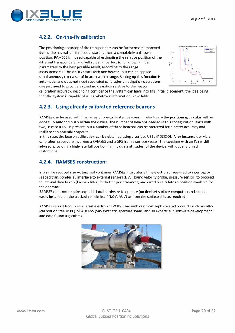
4.2.2. On-the-fly calibration
The positioning accuracy of the transponders can be furthermore improvedduring the navigation, if needed, starting from a completely unknownposition. RAMSES is indeed capable of estimating the relative position of thedifferent transponders, and will adjust imperfect (or unknown) initialparameters to the best possible result, according to the rangemeasurements. This ability starts with one beacon, but can be appliedsimultaneously over a set of beacon within range. Setting up this function isautomatic, and does not need separated calibration / navigation operations:one just need to provide a standard deviation relative to the beaconcalibration accuracy, describing confidence the system can have into this initial placement, the idea beingthat the system is capable of using whatever information is available.
4.2.3. Using already calibrated reference beacons
RAMSES can be used within an array of pre-calibrated beacons, in which case the positioning calculus will bedone fully autonomously within the device. The number of beacons needed in this configuration starts withtwo, in case a DVL is present, but a number of three beacons can be preferred for a better accuracy andresilience to acoustic dropouts.In this case, the beacon calibration can be obtained using a surface USBL (POSIDONIA for instance), or via acalibration procedure involving a RAMSES and a GPS from a surface vessel. The coupling with an INS is stilladvised, providing a high-rate full positioning (including attitudes) of the device, without any timedrestrictions.
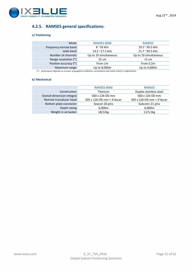
4.2.4. RAMSES construction:
In a single reduced size waterproof container RAMSES integrates all the electronics required to interrogateseabed transponder(s), interface to external sensors (DVL, sound velocity probe, pressure sensor) to proceedto internal data fusion (Kalman filter) for better performances, and directly calculates a position available forthe operator.RAMSES does not require any additional hardware to operate (no deckset surface computer) and can beeasily installed on the tracked vehicle itself (ROV, AUV) or from the surface ship as required.
RAMSES is built from iXBlue latest electronics PCB’s used with our most sophisticated products such as GAPS(calibration free USBL), SHADOWS (SAS synthetic aperture sonar) and all expertise in software developmentand data fusion algorithms.
Aug 22nd , 2014
www.ixsea.com G_ST_TSH_043a Page 21 of 62Global Subsea Positioning Solutions
4.2.5. RAMSES general specifications:
a/ Positioning
Mode RAMSES 6000 RAMSESfrequency narrow band
wide band8 ~16 kHz
14.5 ~17.5 kHz19.5 ~30.5 kHz21.7 ~30.5 kHz
Number of channels Up to 10 simultaneous Up to 10 simultaneousRange resolution (*) 15 cm <5 cmPosition accuracy (*) From 1m From 0.2m
Maximum range Up to 8,000m Up to 4,000m(*) performance depends on acoustic propagation conditions, environment and sound velocity compensation.
b/ Mechanical
RAMSES 6000 RAMSESConstruction Titanium Duplex stainless steel
Overall dimension integralRemote transducer head
560 x 126 OD mm505 x 126 OD mm + X’ducer
560 x 126 OD mm505 x 126 OD mm + X’ducer
Bottom plate connector Seacon 26 pins Subconn 21 pinsDepth rating 6,000m 6,000m
Weight in air/water 18/12kg 11/5.5kg
Aug 22nd , 2014
www.ixsea.com G_ST_TSH_043a Page 22 of 62Global Subsea Positioning Solutions
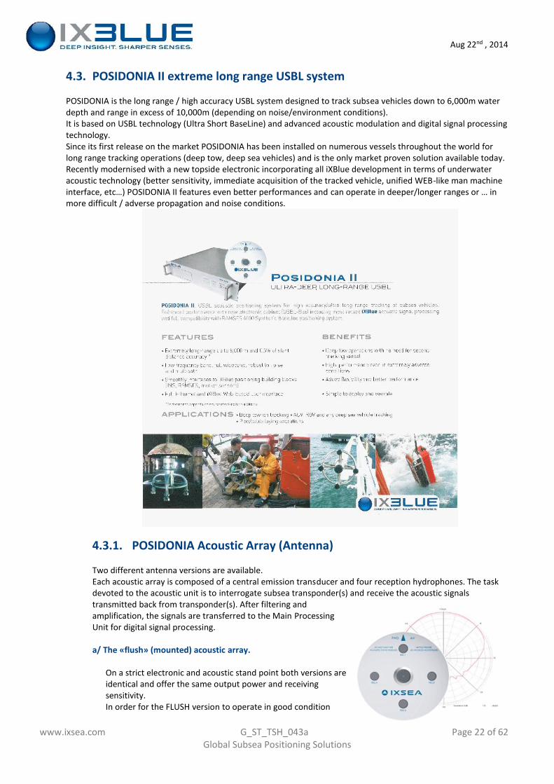
4.3. POSIDONIA II extreme long range USBL system
POSIDONIA is the long range / high accuracy USBL system designed to track subsea vehicles down to 6,000m waterdepth and range in excess of 10,000m (depending on noise/environment conditions).It is based on USBL technology (Ultra Short BaseLine) and advanced acoustic modulation and digital signal processingtechnology.Since its first release on the market POSIDONIA has been installed on numerous vessels throughout the world forlong range tracking operations (deep tow, deep sea vehicles) and is the only market proven solution available today.Recently modernised with a new topside electronic incorporating all iXBlue development in terms of underwateracoustic technology (better sensitivity, immediate acquisition of the tracked vehicle, unified WEB-like man machineinterface, etc…) POSIDONIA II features even better performances and can operate in deeper/longer ranges or … inmore difficult / adverse propagation and noise conditions.
4.3.1. POSIDONIA Acoustic Array (Antenna)
Two different antenna versions are available.Each acoustic array is composed of a central emission transducer and four reception hydrophones. The taskdevoted to the acoustic unit is to interrogate subsea transponder(s) and receive the acoustic signalstransmitted back from transponder(s). After filtering andamplification, the signals are transferred to the Main ProcessingUnit for digital signal processing.
a/ The «flush» (mounted) acoustic array.
On a strict electronic and acoustic stand point both versions areidentical and offer the same output power and receivingsensitivity.In order for the FLUSH version to operate in good condition
Aug 22nd , 2014
www.ixsea.com G_ST_TSH_043a Page 23 of 62Global Subsea Positioning Solutions
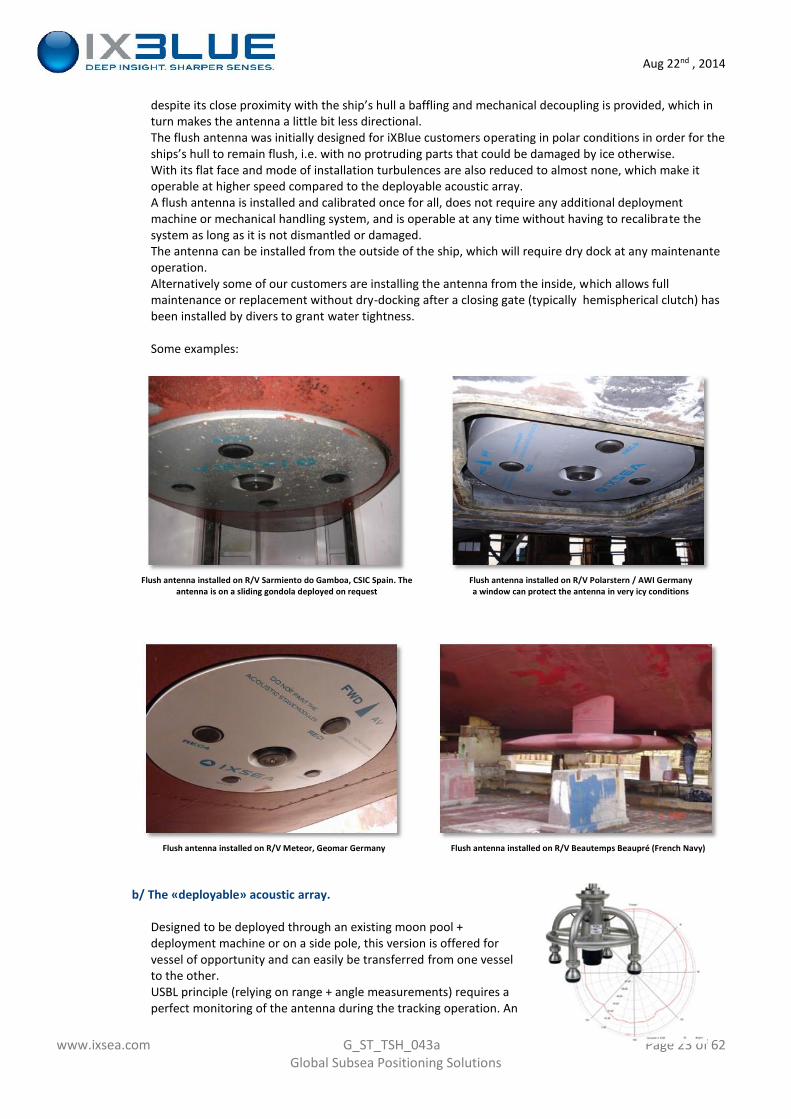
despite its close proximity with the ship’s hull a baffling and mechanical decoupling is provided, which inturn makes the antenna a little bit less directional.The flush antenna was initially designed for iXBlue customers operating in polar conditions in order for theships’s hull to remain flush, i.e. with no protruding parts that could be damaged by ice otherwise.With its flat face and mode of installation turbulences are also reduced to almost none, which make itoperable at higher speed compared to the deployable acoustic array.A flush antenna is installed and calibrated once for all, does not require any additional deploymentmachine or mechanical handling system, and is operable at any time without having to recalibrate thesystem as long as it is not dismantled or damaged.The antenna can be installed from the outside of the ship, which will require dry dock at any maintenanteoperation.Alternatively some of our customers are installing the antenna from the inside, which allows fullmaintenance or replacement without dry-docking after a closing gate (typically hemispherical clutch) hasbeen installed by divers to grant water tightness.
Some examples:
Flush antenna installed on R/V Sarmiento do Gamboa, CSIC Spain. Theantenna is on a sliding gondola deployed on request
Flush antenna installed on R/V Polarstern / AWI Germanya window can protect the antenna in very icy conditions
Flush antenna installed on R/V Meteor, Geomar Germany Flush antenna installed on R/V Beautemps Beaupré (French Navy)
b/ The «deployable» acoustic array.
Designed to be deployed through an existing moon pool +deployment machine or on a side pole, this version is offered forvessel of opportunity and can easily be transferred from one vesselto the other.USBL principle (relying on range + angle measurements) requires aperfect monitoring of the antenna during the tracking operation. An
Aug 22nd , 2014
www.ixsea.com G_ST_TSH_043a Page 24 of 62Global Subsea Positioning Solutions
initial calibration is performed during system installation which will remain valid until the “deployable”antenna is moved to a different place or ship.In order to keep a calibration valid during system lifetime, the use of a deployment machine isrecommended (iXBlue deployment machine HISYS here after).In case of a pole mount installation the use of an iXBlue OCTANS heading and motion sensor right abovethis antenna is the right solution.Simple pole mount will require a full calibration before every operation, i.e. 4 to 8 hours vessel timedepending on water depth and operators skills.iXBlue does not normally supply the pole mount hardware (if this option is selected) which is particular toevery single ship, nor hull work on the ship should it be necessary.
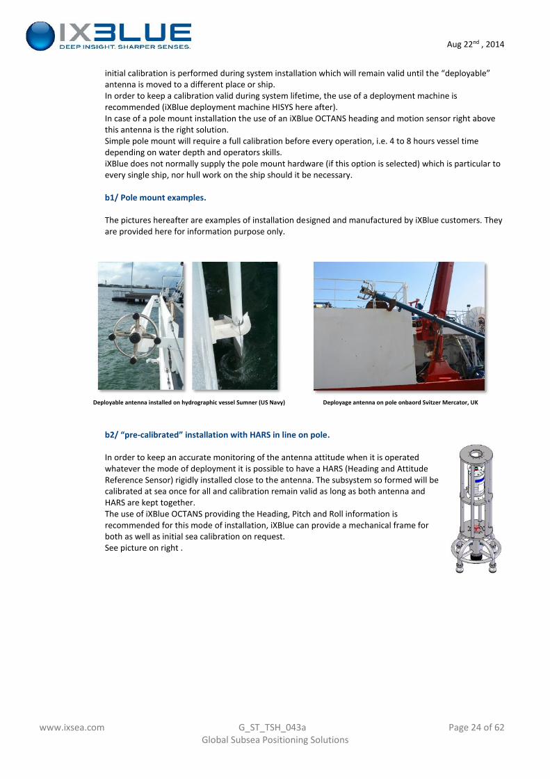
b1/ Pole mount examples.
The pictures hereafter are examples of installation designed and manufactured by iXBlue customers. Theyare provided here for information purpose only.
Deployable antenna installed on hydrographic vessel Sumner (US Navy) Deployage antenna on pole onbaord Svitzer Mercator, UK
b2/ “pre-calibrated” installation with HARS in line on pole.
In order to keep an accurate monitoring of the antenna attitude when it is operatedwhatever the mode of deployment it is possible to have a HARS (Heading and AttitudeReference Sensor) rigidly installed close to the antenna. The subsystem so formed will becalibrated at sea once for all and calibration remain valid as long as both antenna andHARS are kept together.The use of iXBlue OCTANS providing the Heading, Pitch and Roll information isrecommended for this mode of installation, iXBlue can provide a mechanical frame forboth as well as initial sea calibration on request.See picture on right .
Aug 22nd , 2014
www.ixsea.com G_ST_TSH_043a Page 25 of 62Global Subsea Positioning Solutions
Deployable antenna and OCTANS on R/V Jeoje / KOREA Deployable antenna and OCTANS
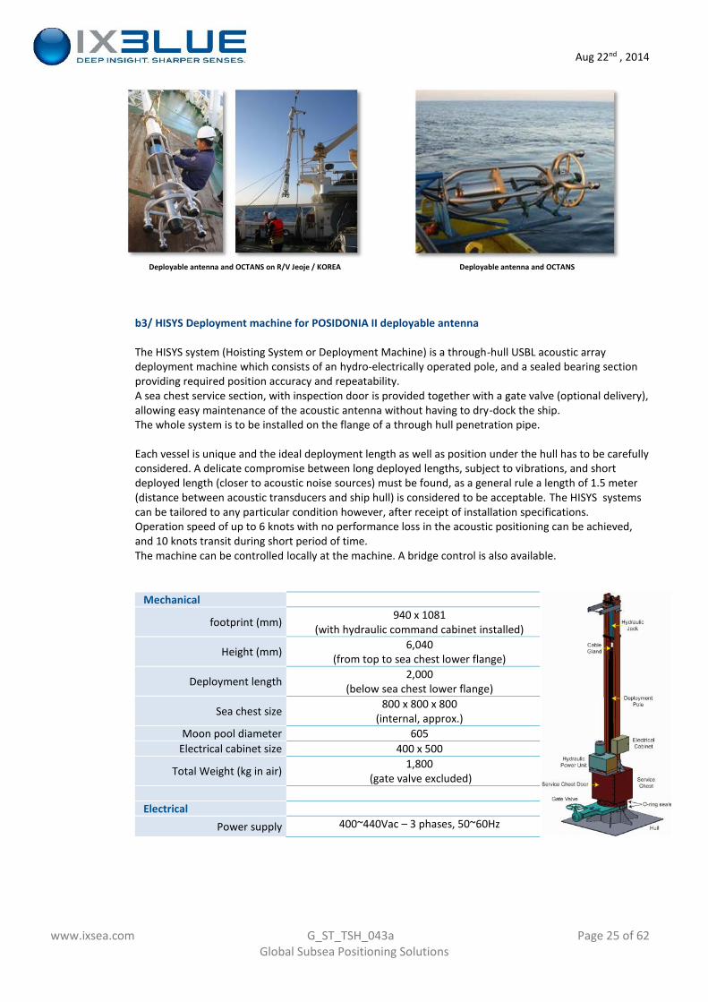
b3/ HISYS Deployment machine for POSIDONIA II deployable antenna
The HISYS system (Hoisting System or Deployment Machine) is a through-hull USBL acoustic arraydeployment machine which consists of an hydro-electrically operated pole, and a sealed bearing sectionproviding required position accuracy and repeatability.A sea chest service section, with inspection door is provided together with a gate valve (optional delivery),allowing easy maintenance of the acoustic antenna without having to dry-dock the ship.The whole system is to be installed on the flange of a through hull penetration pipe.
Each vessel is unique and the ideal deployment length as well as position under the hull has to be carefullyconsidered. A delicate compromise between long deployed lengths, subject to vibrations, and shortdeployed length (closer to acoustic noise sources) must be found, as a general rule a length of 1.5 meter(distance between acoustic transducers and ship hull) is considered to be acceptable. The HISYS systemscan be tailored to any particular condition however, after receipt of installation specifications.Operation speed of up to 6 knots with no performance loss in the acoustic positioning can be achieved,and 10 knots transit during short period of time.The machine can be controlled locally at the machine. A bridge control is also available.
Mechanical
footprint (mm) 940 x 1081(with hydraulic command cabinet installed)
Height (mm) 6,040(from top to sea chest lower flange)
Deployment length 2,000(below sea chest lower flange)
Sea chest size 800 x 800 x 800(internal, approx.)
Moon pool diameter 605Electrical cabinet size 400 x 500
Total Weight (kg in air) 1,800(gate valve excluded)
ElectricalPower supply 400~440Vac – 3 phases, 50~60Hz
Aug 22nd , 2014
www.ixsea.com G_ST_TSH_043a Page 26 of 62Global Subsea Positioning Solutions
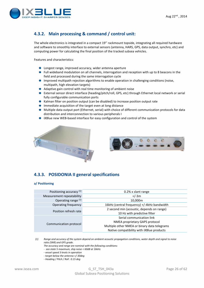
4.3.2. Main processing & command / control unit:
The whole electronics is integrated in a compact 19’’ rackmount topside, integrating all required hardwareand software to smoothly interface to external sensors (antenna, HARS, GPS, data output, synchro, etc) andcomputing power for calculating the final position of the tracked subsea vehicles.
Features and characteristics:
Longest range, improved accuracy, wider antenna apertureFull wideband modulation on all channels, interrogation and reception with up to 8 beacons in thefield and processed during the same interrogation cycleImproved multipath rejection algorithms to enable operation in challenging conditions (noise,multipath, high elevation targets)Adaptive gain control with real time monitoring of ambient noiseExternal sensor direct interface (heading/pitch/roll, GPS, etc) through Ethernet local network or serialfully configurable communication portsKalman filter on position output (can be disabled) to increase position output rateImmediate acquisition of the target even at long distanceMultiple data output port (Ethernet, serial) with choice of different communication protocols for datadistribution and interconnection to various peripherals IiXBlue new WEB-based interface for easy configuration and control of the system
4.3.3. POSIDONIA II general specifications
a/ Positioning
Positioning accuracy (1) 0.2% x slant rangeMeasurement repeatability +/-3m
Operating range (1) 10,000mOperating frequency 16kHz (central frequency) +/-4kHz bandwidth
Position refresh rate 2 second min (acoustic, depends on range)10 Hz with predictive filter
Communication protocol
Serial communication linkNMEA proprietary GAPS protocol
Multiple other NMEA or binary data telegramsNative compatibility with iXBlue products
(1) Range and accuracy of the system depend on ambient acoustic propagation conditions, water depth and signal to noiseratio (SNR) and GPS grade.The accuracy and range are nominal with the following conditions:- sea state 5 maximum, ship noise < 60dB at 16kHz- vessel speed 3 knots in operation- target below the antenna +/-30deg- Heading / Pitch / Roll : 0.15 deg
Aug 22nd , 2014
www.ixsea.com G_ST_TSH_043a Page 27 of 62Global Subsea Positioning Solutions
- Sound Velocity Profile ideally compensated- System calibrated (antenna v.s. HARS aligned)
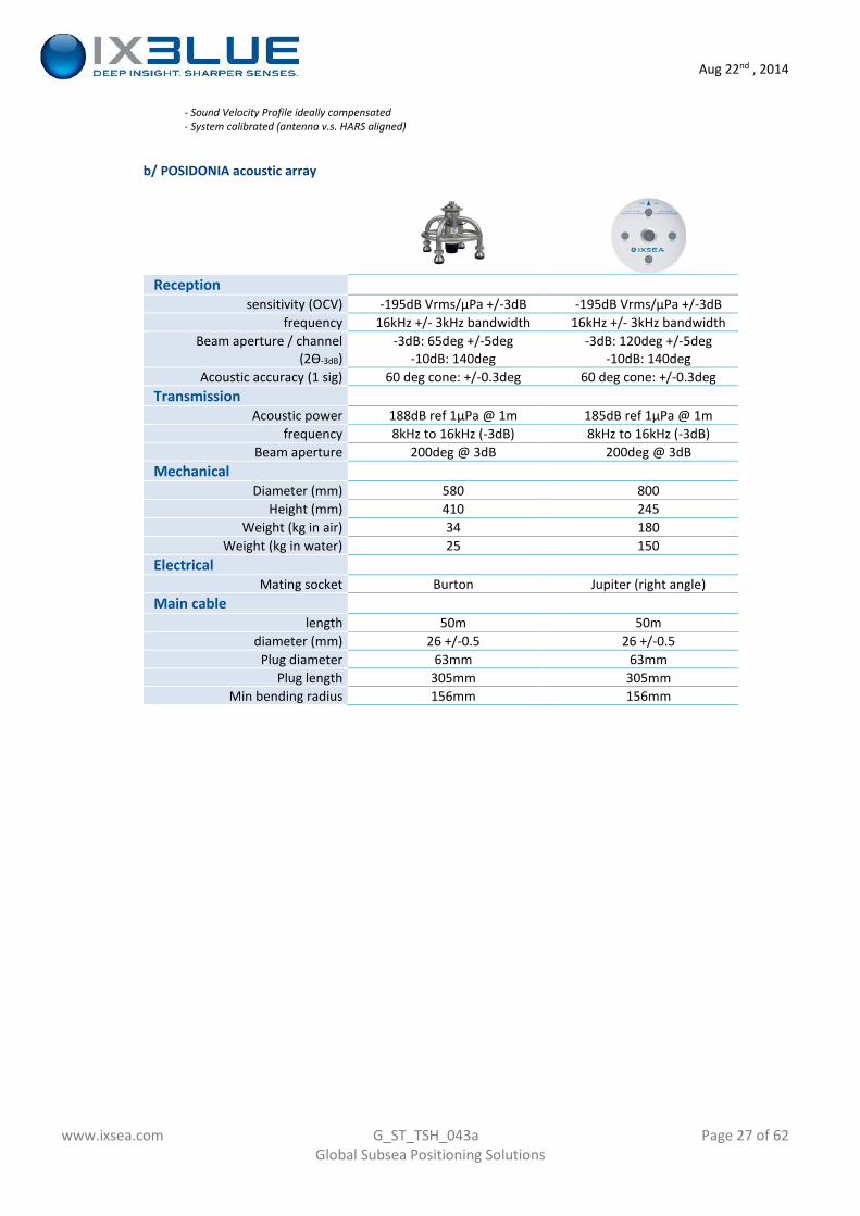
b/ POSIDONIA acoustic array
Receptionsensitivity (OCV) -195dB Vrms/µPa +/-3dB -195dB Vrms/µPa +/-3dB
frequency 16kHz +/- 3kHz bandwidth 16kHz +/- 3kHz bandwidthBeam aperture / channel
(2Ɵ-3dB)-3dB: 65deg +/-5deg
-10dB: 140deg-3dB: 120deg +/-5deg
-10dB: 140degAcoustic accuracy (1 sig) 60 deg cone: +/-0.3deg 60 deg cone: +/-0.3deg
TransmissionAcoustic power 188dB ref 1µPa @ 1m 185dB ref 1µPa @ 1m
frequency 8kHz to 16kHz (-3dB) 8kHz to 16kHz (-3dB)Beam aperture 200deg @ 3dB 200deg @ 3dB
MechanicalDiameter (mm) 580 800
Height (mm) 410 245Weight (kg in air) 34 180
Weight (kg in water) 25 150Electrical
Mating socket Burton Jupiter (right angle)Main cable
length 50m 50mdiameter (mm) 26 +/-0.5 26 +/-0.5
Plug diameter 63mm 63mmPlug length 305mm 305mm
Min bending radius 156mm 156mm
Aug 22nd , 2014
www.ixsea.com G_ST_TSH_043a Page 28 of 62Global Subsea Positioning Solutions
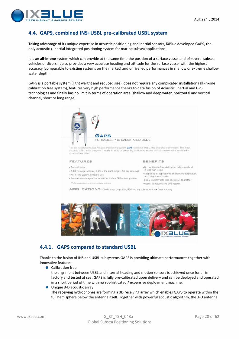
4.4. GAPS, combined INS+USBL pre-calibrated USBL system
Taking advantage of its unique expertise in acoustic positioning and inertial sensors, iXBlue developed GAPS, theonly acoustic + inertial integrated positioning system for marine subsea applications.
It is an all-in-one system which can provide at the same time the position of a surface vessel and of several subseavehicles or divers. It also provides a very accurate heading and attitude for the surface vessel with the highestaccuracy (comparable to existing systems on the market) and unrivalled performances in shallow or extreme shallowwater depth.
GAPS is a portable system (light weight and reduced size), does not require any complicated installation (all-in-onecalibration free system), features very high performance thanks to data fusion of Acoustic, inertial and GPStechnologies and finally has no limit in terms of operation area (shallow and deep water, horizontal and verticalchannel, short or long range).
4.4.1. GAPS compared to standard USBL
Thanks to the fusion of INS and USBL subsystems GAPS is providing ultimate performances together withinnovative features:
Calibration free:the alignment between USBL and internal heading and motion sensors is achieved once for all infactory and tested at sea. GAPS is fully pre-calibrated upon delivery and can be deployed and operatedin a short period of time with no sophisticated / expensive deployment machine.Unique 3-D acoustic array:The receiving hydrophones are forming a 3D receiving array which enables GAPS to operate within thefull hemisphere below the antenna itself. Together with powerful acoustic algorithm, the 3-D antenna
Aug 22nd , 2014
www.ixsea.com G_ST_TSH_043a Page 29 of 62Global Subsea Positioning Solutions
makes GAPS able to work from extreme shallow water / high elevation tracking to deep sea / verticaltracking.All-in-one system:all components required for positioning are included in the system. This turn-key configuration allowsquick mobilization and operation with no loss of time in interfacing ancillary sensors used withconventional USBL. (GPS, heading, pitch/roll sensors, computer)High accuracy:motion compensation is directly taken into account in the instrument itself with high performancesINS (PHINS grade, 0.01deg H/P/R).Sophisticated signal processing and wideband efficient modulation allows a stunning 0.2% x slantrange absolute accuracy, all errors included.User friendly. The integral system just need initial setting (offset, transponders information) and willstart working immediately after powering on.The new iXBlue WEB-based unified Man Machine Interface is now available with GAPS-NG
An alien in the USBL world when first released, GAPS proved its performance and features with customersworldwide / all market application since then. GAPS-NG latest product generation now in production is againpushing the limits of acoustic subsea positioning.
4.4.2. GAPS-NG new product generation
With the experience accumulated over the last 4 to 5 years and customers’ feedback GAPS has been recentlyupgraded and fitted with new features which open the scope of application of the product, and a potential toprogressively add further functionalities.
Standard GAPS-NG is now coming with the following base configuration:
Range, accuracy: 4,000m range and 0.2% x slant range (with nominal propagation, noise andenvironmental conditionsEthernet communication link (4 virtual ports) and serial RS232/RS422 communication port. All userconfigurableStandard iXBlue unified WEB-based Man Machine InterfaceFull access to internal INS data (PHINS-like) wth all PHINS communication protocols and data rateFull wide-band modulation capability (interrogation + reply) to operate with ETA / RTA iXBluetranspondersDelph RoadMap display softwareNew optional features and functionalities to be progressively added to the product:o Compatibility with some other manufacturers’ transponders. (please apply to the factory for
detailed available compatibility modes)o Enhanced DP modes (L/USBL, station keeping)o Telemetry
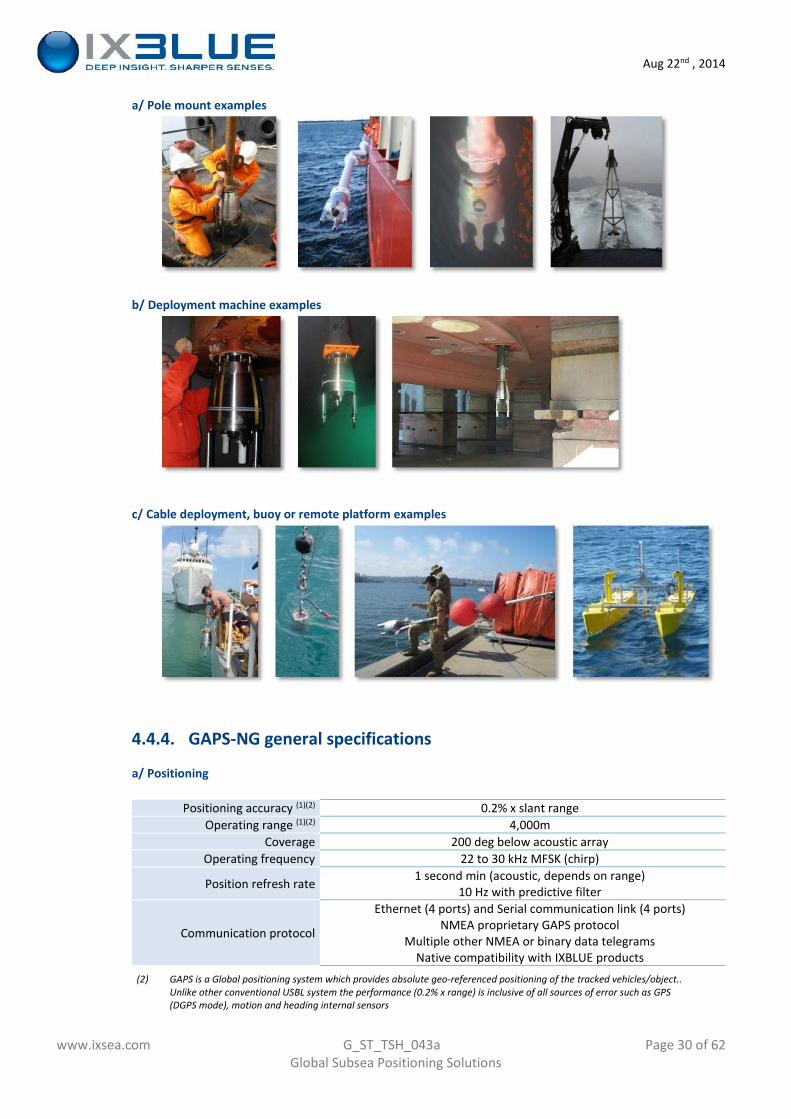
4.4.3. GAPS-NG example of installation
The few pictures here after demonstrate the flexibility of the GAPS system in terms of operation. Theseinstallation examples all provided by our customers are possible thanks to the internal INS installed in theinstrument (pre-calibrated feature) together with the compactness and extreme integration of the system.(reduces size and weight, all integrated system)
Aug 22nd , 2014
www.ixsea.com G_ST_TSH_043a Page 30 of 62Global Subsea Positioning Solutions
a/ Pole mount examples
b/ Deployment machine examples
c/ Cable deployment, buoy or remote platform examples
4.4.4. GAPS-NG general specifications
a/ Positioning
Positioning accuracy (1)(2) 0.2% x slant rangeOperating range (1)(2) 4,000m
Coverage 200 deg below acoustic arrayOperating frequency 22 to 30 kHz MFSK (chirp)
Position refresh rate 1 second min (acoustic, depends on range)10 Hz with predictive filter
Communication protocol
Ethernet (4 ports) and Serial communication link (4 ports)NMEA proprietary GAPS protocol
Multiple other NMEA or binary data telegramsNative compatibility with IXBLUE products
(2) GAPS is a Global positioning system which provides absolute geo-referenced positioning of the tracked vehicles/object..Unlike other conventional USBL system the performance (0.2% x range) is inclusive of all sources of error such as GPS(DGPS mode), motion and heading internal sensors
Aug 22nd , 2014
www.ixsea.com G_ST_TSH_043a Page 31 of 62Global Subsea Positioning Solutions
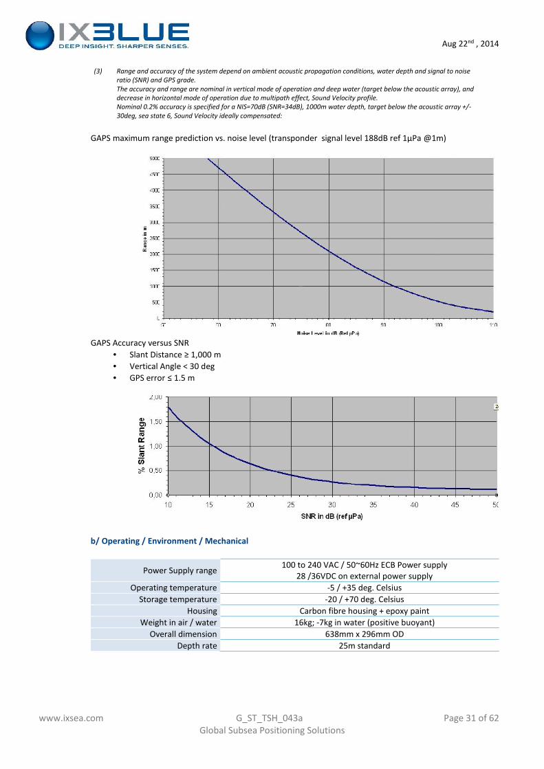
(3) Range and accuracy of the system depend on ambient acoustic propagation conditions, water depth and signal to noiseratio (SNR) and GPS grade.The accuracy and range are nominal in vertical mode of operation and deep water (target below the acoustic array), anddecrease in horizontal mode of operation due to multipath effect, Sound Velocity profile.Nominal 0.2% accuracy is specified for a NIS=70dB (SNR=34dB), 1000m water depth, target below the acoustic array +/-30deg, sea state 6, Sound Velocity ideally compensated:
GAPS maximum range prediction vs. noise level (transponder signal level 188dB ref 1µPa @1m)
GAPS Accuracy versus SNR Slant Distance ≥ 1,000 m Vertical Angle < 30 deg GPS error ≤ 1.5 m
b/ Operating / Environment / Mechanical
Power Supply range 100 to 240 VAC / 50~60Hz ECB Power supply28 /36VDC on external power supply
Operating temperature -5 / +35 deg. CelsiusStorage temperature -20 / +70 deg. Celsius
Housing Carbon fibre housing + epoxy paintWeight in air / water 16kg; -7kg in water (positive buoyant)
Overall dimension 638mm x 296mm ODDepth rate 25m standard
Aug 22nd , 2014
www.ixsea.com G_ST_TSH_043a Page 32 of 62Global Subsea Positioning Solutions
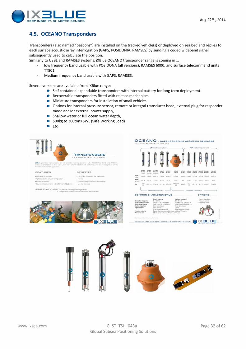
4.5. OCEANO Transponders
Transponders (also named “beacons”) are installed on the tracked vehicle(s) or deployed on sea bed and replies toeach surface acoustic array interrogation (GAPS, POSIDONIA, RAMSES) by sending a coded wideband signalsubsequently used to calculate the position.Similarly to USBL and RAMSES systems, iXBlue OCEANO transponder range is coming in …
- low frequency band usable with POSIDONA (all versions), RAMSES 6000, and surface telecommand unitsTT801
- Medium frequency band usable with GAPS, RAMSES.
Several versions are available from iXBlue range:Self contained expandable transponders with internal battery for long term deploymentRecoverable transponders fitted with release mechanismMiniature transponders for installation of small vehiclesOptions for internal pressure sensor, remote or integral transducer head, external plug for respondermode and/or external power supply,Shallow water or full ocean water depth,500kg to 300tons SWL (Safe Working Load)Etc
Aug 22nd , 2014
www.ixsea.com G_ST_TSH_043a Page 33 of 62Global Subsea Positioning Solutions
4.5.1. Recommended LF transponder for POSIDONIA II and RAMSES 6000
a/ POSIDONIA system initial calibration
USBL principle requires a perfect knowledge of the attitude of the acoustic array (both in heading andP/R) to measure angles to the tracked targets and calculate position.The calibration procedure is used to measure and compensate the mechanical misalignments betweenthe acoustic array, the Heading/motion sensor and the horizontal plan after initial installation. Thisprocedure will have to be repeated every time the antenna is removed, or during regular inspections. (typonce every year)
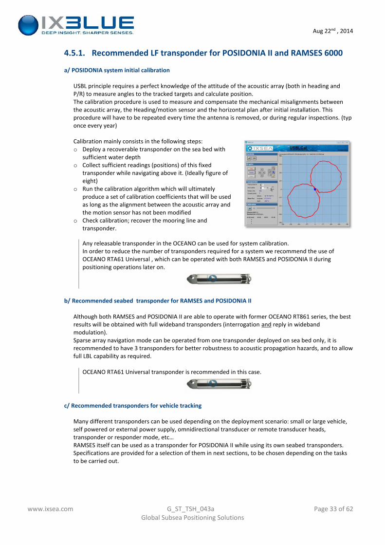
Calibration mainly consists in the following steps:o Deploy a recoverable transponder on the sea bed with
sufficient water deptho Collect sufficient readings (positions) of this fixed
transponder while navigating above it. (Ideally figure ofeight)
o Run the calibration algorithm which will ultimatelyproduce a set of calibration coefficients that will be usedas long as the alignment between the acoustic array andthe motion sensor has not been modified
o Check calibration; recover the mooring line andtransponder.
Any releasable transponder in the OCEANO can be used for system calibration.In order to reduce the number of transponders required for a system we recommend the use ofOCEANO RTA61 Universal , which can be operated with both RAMSES and POSIDONIA II duringpositioning operations later on.
b/ Recommended seabed transponder for RAMSES and POSIDONIA II
Although both RAMSES and POSIDONIA II are able to operate with former OCEANO RT861 series, the bestresults will be obtained with full wideband transponders (interrogation and reply in widebandmodulation).Sparse array navigation mode can be operated from one transponder deployed on sea bed only, it isrecommended to have 3 transponders for better robustness to acoustic propagation hazards, and to allowfull LBL capability as required.
OCEANO RTA61 Universal transponder is recommended in this case.
c/ Recommended transponders for vehicle tracking
Many different transponders can be used depending on the deployment scenario: small or large vehicle,self powered or external power supply, omnidirectional transducer or remote transducer heads,transponder or responder mode, etc…RAMSES itself can be used as a transponder for POSIDONIA II while using its own seabed transponders.Specifications are provided for a selection of them in next sections, to be chosen depending on the tasksto be carried out.
Aug 22nd , 2014
www.ixsea.com G_ST_TSH_043a Page 34 of 62Global Subsea Positioning Solutions
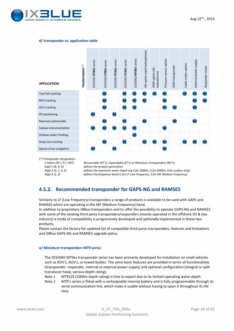
d/ transponder vs. application table
APPLICATIONTR
ANSP
ON
DER
(*)
OCE
ANO
RT86
1se
ries
OCE
ANO
ET86
1se
ries
OCE
ANO
RTA6
1se
ries
OCE
ANO
ETA6
1se
ries
OCE
ANO
MT8
61se
ries
HD o
ptio
n (s
plit
hydr
opho
ne)
HDIR
opt
ion
(dir.
hydr
opho
ne)
Pres
sure
sens
or o
ptio
n
OEM
tran
spon
der
Cabl
e cu
tter
opt
ion
Exte
rnal
pow
er su
pply
Resp
onde
r mod
e
Tow fish tracking
ROV tracking
AUV tracking
DP positioning
Manned submersible
Subsea instrumentation
Shallow water tracking
Deep tow tracking
Sparse array navigation
(*) Transponder designation:2 letters (RT / ET / MT) Recoverable (RT’s), Expandable (ET’s) or Miniature Transponders (MT’s)Digit 1 (8, 9, A) defines the product generationDigit 2 (0, 1, 3, 6) defines the maximum water depth (eg 3 for 3000m, 6 for 6000m, 0 for surface only)Digit 3 (1, 2) defines the frequency band (1 for LF Low Frequency, 2 for MF Medium Frequency)
4.5.2. Recommended transponder for GAPS-NG and RAMSES
Similarly to LF (Low Frequency) transponders a range of products is available to be used with GAPS andRAMSES which are operating in the MF (Medium Frequency) band.In addition to proprietary iXBlue transponders and to offer the possibility to operate GAPS-NG and RAMSESwith some of the existing third party transponders/responders (mostly operated in the offshore Oil & Gasindustry) a mode of compatibility is progressively developed and optionally implemented in these twoproducts.Please contact the factory for updated list of compatible third party transponders, features and limitationsand iXBlue GAPS-NG and RAMSES upgrade policy.
a/ Miniature transponders MT9 series
The OCEANO MT9xx transponder series has been primarily developed for installation on small vehiclessuch as ROV’s, AUV’s, or towed bodies. The same basic features are provided in terms of functionalities(transponder, responder, internal or external power supply) and optional configuration (integral or splittransducer head, various depth rating).Note 1 MT912S (1000m depth rating) is free to export due to its limited operating water depthNote 2 MT9’s series is fitted with a rechargeable internal battery and is fully programmable through its
serial communication link, which make it usable without having to open it throughout its lifetime
Aug 22nd , 2014
www.ixsea.com G_ST_TSH_043a Page 35 of 62Global Subsea Positioning Solutions
Note 3 previous generation MT8 series is still available and supported however we do recommend theuse of MT9 series for new projects
OCEANO MT912S miniature transponder (integral transducer head shown on picture).
b/ full size Medium Frequency transponders for GAPS-NG / RAMSES
RTA / ETA’s transponders have been developed originally to be used with RAMSES. They can be used withGAPS-NG (latest generation) which is sharing the same frequency band and modulation.Thanks to their additional functionalities (releasable version RTA, larger battery autonomy) ETA / RTA’swill be appropriate whenever long life transponders are required, of in case of DP or sparse arraynavigation applications.
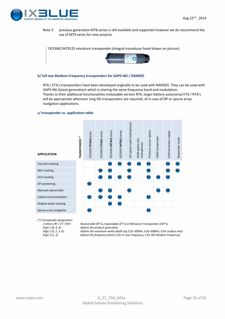
c/ transponder vs. application table
APPLICATION
TRAN
SPO
NDE
R(*
)
OCE
ANO
RTA6
2ser
ies
OCE
ANO
ETA6
2se
ries
OCE
ANO
MT9
x2se
ries
OCE
ANO
MT8
x2se
ries
HD o
ptio
n (s
plit
hydr
opho
ne)
HDIR
opt
ion
(dir.
hydr
opho
ne)
Pres
sure
sens
or o
ptio
n
OEM
tran
spon
der
Exte
rnal
pow
er su
pply
Resp
onde
r mod
e
Tow fish tracking
ROV tracking
AUV tracking
DP positioning
Manned submersible
Subsea instrumentation
Shallow water tracking
Sparse array navigation
(*) Transponder designation:2 letters (RT / ET / MT) Recoverable (RT’s), Expandable (ET’s) or Miniature Transponders (MT’s)Digit 1 (8, 9, A) defines the product generationDigit 2 (0, 1, 3, 6) defines the maximum water depth (eg 3 for 3000m, 6 for 6000m, 0 for surface only)Digit 3 (1, 2) defines the frequency band (1 for LF Low Frequency, 2 for MF Medium Frequency)
Aug 22nd , 2014
www.ixsea.com G_ST_TSH_043a Page 36 of 62Global Subsea Positioning Solutions
4.6. Software and firmware
4.6.1. iXBlue unified WEB-based MMI (Man Machine Interface)
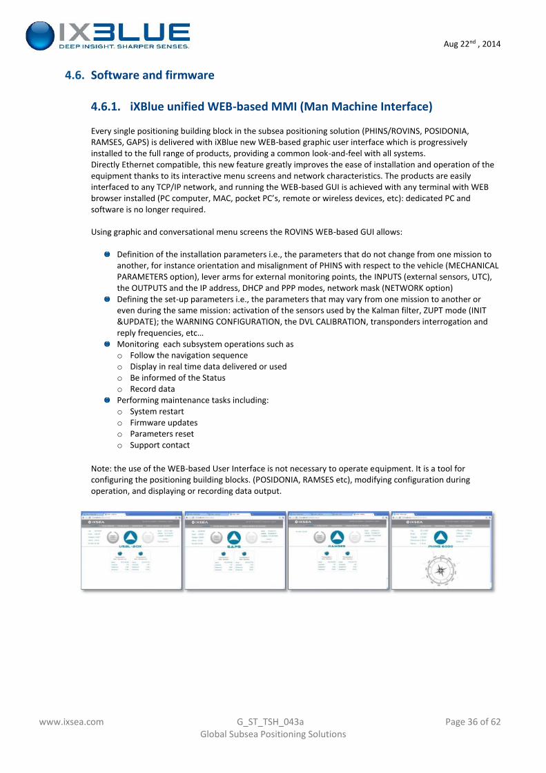
Every single positioning building block in the subsea positioning solution (PHINS/ROVINS, POSIDONIA,RAMSES, GAPS) is delivered with iXBlue new WEB-based graphic user interface which is progressivelyinstalled to the full range of products, providing a common look-and-feel with all systems.Directly Ethernet compatible, this new feature greatly improves the ease of installation and operation of theequipment thanks to its interactive menu screens and network characteristics. The products are easilyinterfaced to any TCP/IP network, and running the WEB-based GUI is achieved with any terminal with WEBbrowser installed (PC computer, MAC, pocket PC’s, remote or wireless devices, etc): dedicated PC andsoftware is no longer required.
Using graphic and conversational menu screens the ROVINS WEB-based GUI allows:
Definition of the installation parameters i.e., the parameters that do not change from one mission toanother, for instance orientation and misalignment of PHINS with respect to the vehicle (MECHANICALPARAMETERS option), lever arms for external monitoring points, the INPUTS (external sensors, UTC),the OUTPUTS and the IP address, DHCP and PPP modes, network mask (NETWORK option)Defining the set-up parameters i.e., the parameters that may vary from one mission to another oreven during the same mission: activation of the sensors used by the Kalman filter, ZUPT mode (INIT&UPDATE); the WARNING CONFIGURATION, the DVL CALIBRATION, transponders interrogation andreply frequencies, etc…Monitoring each subsystem operations such aso Follow the navigation sequenceo Display in real time data delivered or usedo Be informed of the Statuso Record dataPerforming maintenance tasks including:o System restarto Firmware updateso Parameters reseto Support contact
Note: the use of the WEB-based User Interface is not necessary to operate equipment. It is a tool forconfiguring the positioning building blocks. (POSIDONIA, RAMSES etc), modifying configuration duringoperation, and displaying or recording data output.
Aug 22nd , 2014
www.ixsea.com G_ST_TSH_043a Page 37 of 62Global Subsea Positioning Solutions
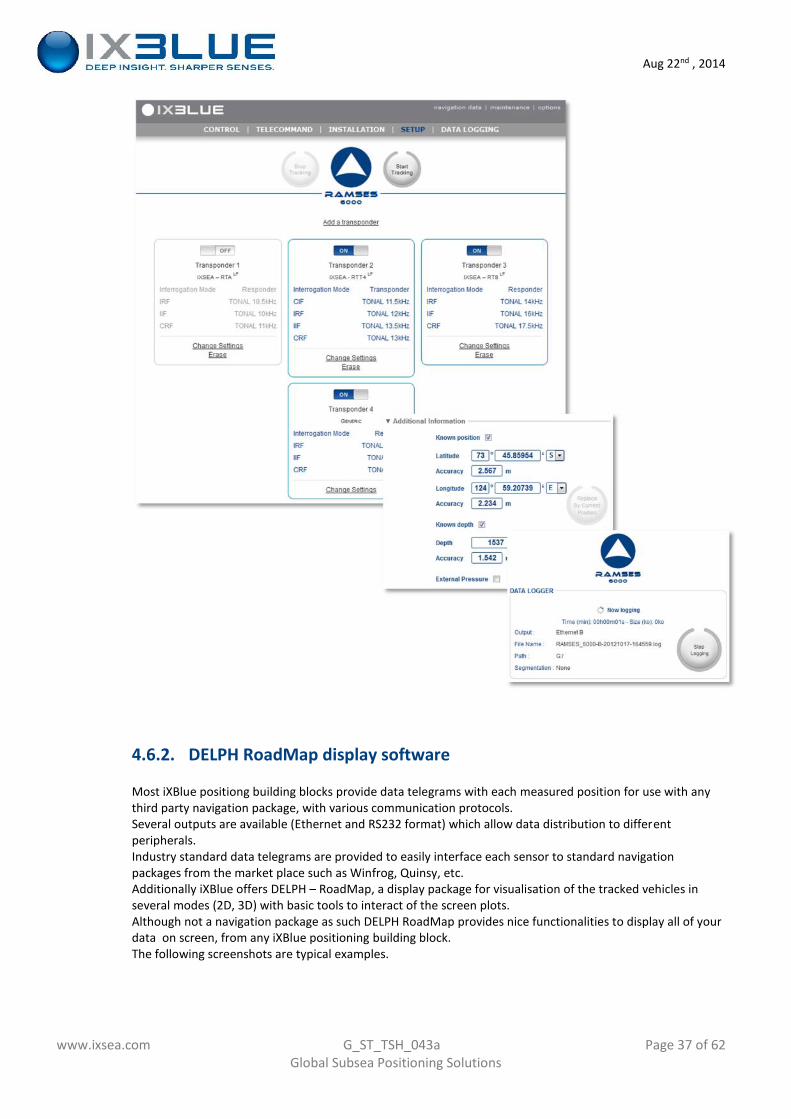
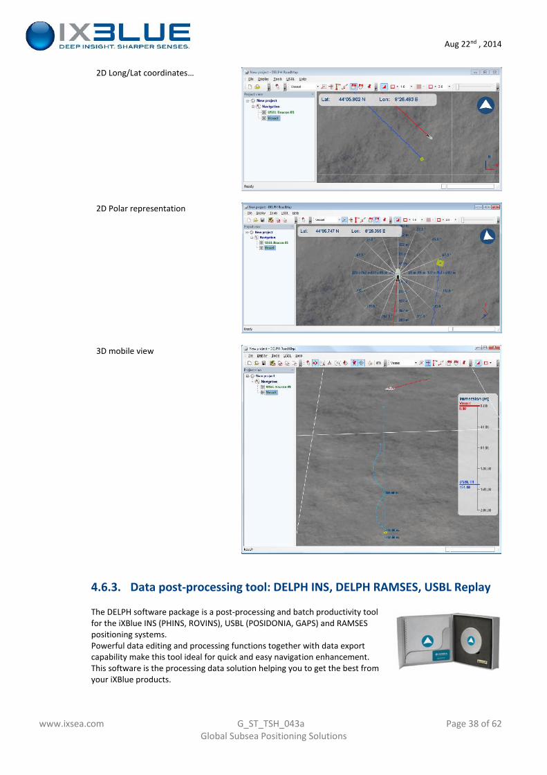
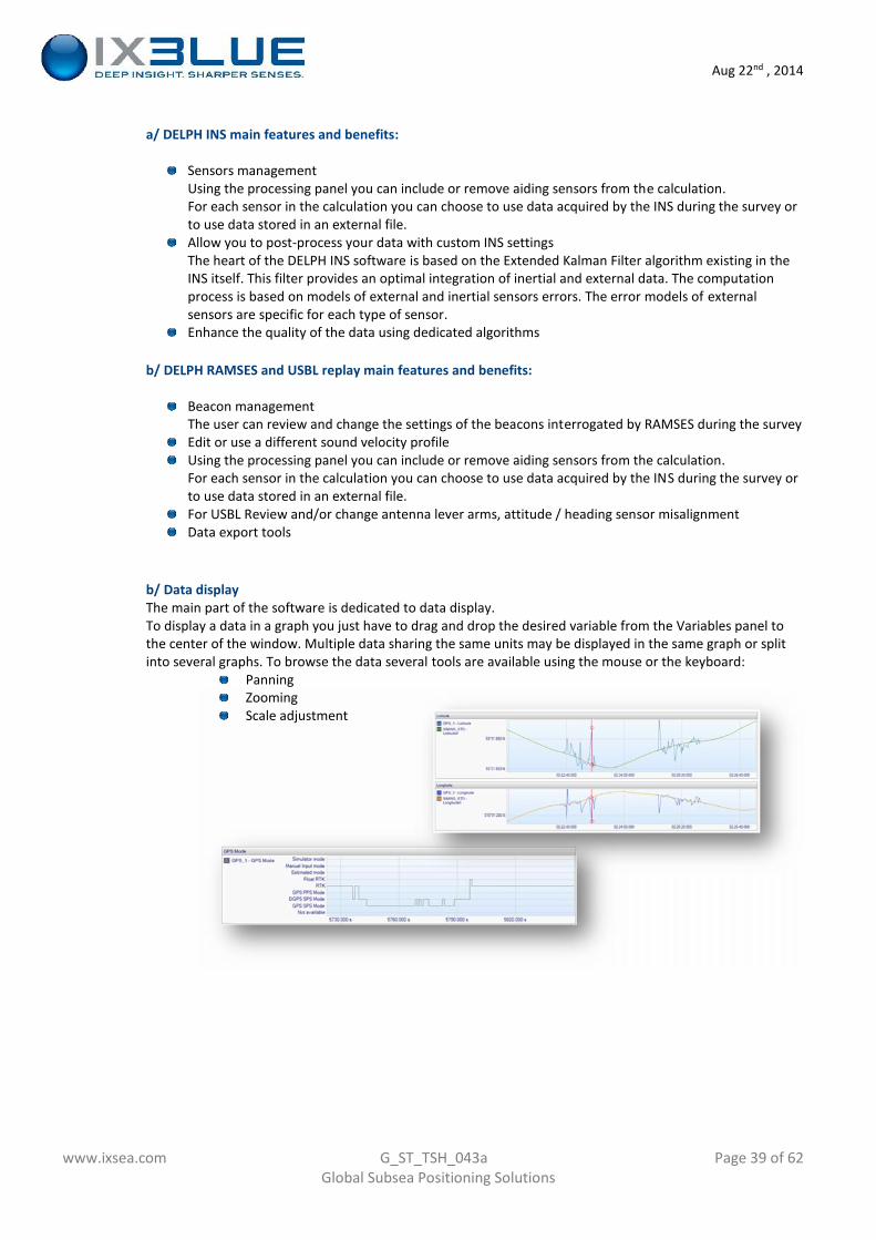
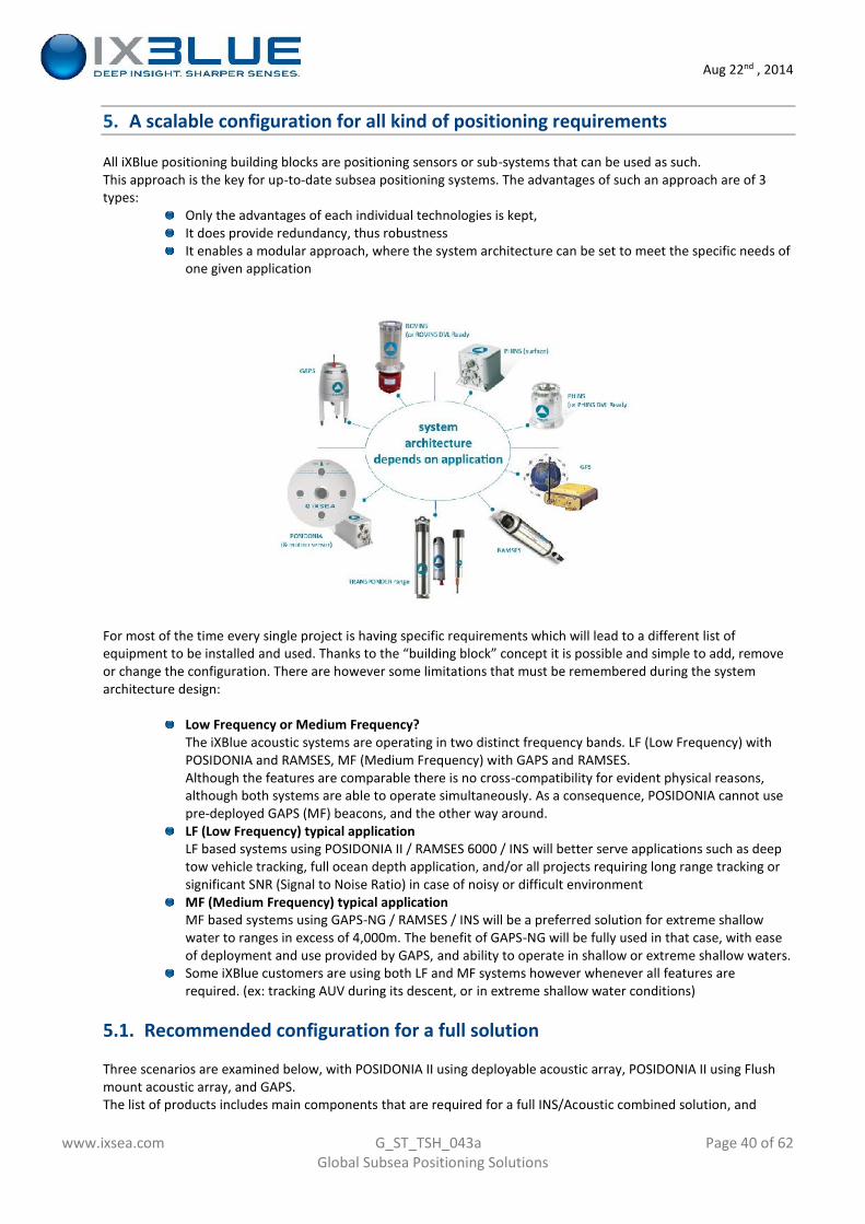
4.6.2. DELPH RoadMap display software
Most iXBlue positiong building blocks provide data telegrams with each measured position for use with anythird party navigation package, with various communication protocols.Several outputs are available (Ethernet and RS232 format) which allow data distribution to differentperipherals.Industry standard data telegrams are provided to easily interface each sensor to standard navigationpackages from the market place such as Winfrog, Quinsy, etc.Additionally iXBlue offers DELPH – RoadMap, a display package for visualisation of the tracked vehicles inseveral modes (2D, 3D) with basic tools to interact of the screen plots.Although not a navigation package as such DELPH RoadMap provides nice functionalities to display all of yourdata on screen, from any iXBlue positioning building block.The following screenshots are typical examples.
Aug 22nd , 2014
www.ixsea.com G_ST_TSH_043a Page 38 of 62Global Subsea Positioning Solutions
2D Long/Lat coordinates…
2D Polar representation
3D mobile view
4.6.3. Data post-processing tool: DELPH INS, DELPH RAMSES, USBL Replay
The DELPH software package is a post-processing and batch productivity toolfor the iXBlue INS (PHINS, ROVINS), USBL (POSIDONIA, GAPS) and RAMSESpositioning systems.Powerful data editing and processing functions together with data exportcapability make this tool ideal for quick and easy navigation enhancement.This software is the processing data solution helping you to get the best fromyour iXBlue products.
Aug 22nd , 2014
www.ixsea.com G_ST_TSH_043a Page 39 of 62Global Subsea Positioning Solutions
a/ DELPH INS main features and benefits:
Sensors managementUsing the processing panel you can include or remove aiding sensors from the calculation.For each sensor in the calculation you can choose to use data acquired by the INS during the survey orto use data stored in an external file.Allow you to post-process your data with custom INS settingsThe heart of the DELPH INS software is based on the Extended Kalman Filter algorithm existing in theINS itself. This filter provides an optimal integration of inertial and external data. The computationprocess is based on models of external and inertial sensors errors. The error models of externalsensors are specific for each type of sensor.Enhance the quality of the data using dedicated algorithms
b/ DELPH RAMSES and USBL replay main features and benefits:
Beacon managementThe user can review and change the settings of the beacons interrogated by RAMSES during the surveyEdit or use a different sound velocity profileUsing the processing panel you can include or remove aiding sensors from the calculation.For each sensor in the calculation you can choose to use data acquired by the INS during the survey orto use data stored in an external file.For USBL Review and/or change antenna lever arms, attitude / heading sensor misalignmentData export tools
b/ Data displayThe main part of the software is dedicated to data display.To display a data in a graph you just have to drag and drop the desired variable from the Variables panel tothe center of the window. Multiple data sharing the same units may be displayed in the same graph or splitinto several graphs. To browse the data several tools are available using the mouse or the keyboard:
PanningZoomingScale adjustment
Aug 22nd , 2014
www.ixsea.com G_ST_TSH_043a Page 40 of 62Global Subsea Positioning Solutions
5. A scalable configuration for all kind of positioning requirements
All iXBlue positioning building blocks are positioning sensors or sub-systems that can be used as such.This approach is the key for up-to-date subsea positioning systems. The advantages of such an approach are of 3types:
Only the advantages of each individual technologies is kept,It does provide redundancy, thus robustnessIt enables a modular approach, where the system architecture can be set to meet the specific needs ofone given application
For most of the time every single project is having specific requirements which will lead to a different list ofequipment to be installed and used. Thanks to the “building block” concept it is possible and simple to add, removeor change the configuration. There are however some limitations that must be remembered during the systemarchitecture design:
Low Frequency or Medium Frequency?The iXBlue acoustic systems are operating in two distinct frequency bands. LF (Low Frequency) withPOSIDONIA and RAMSES, MF (Medium Frequency) with GAPS and RAMSES.Although the features are comparable there is no cross-compatibility for evident physical reasons,although both systems are able to operate simultaneously. As a consequence, POSIDONIA cannot usepre-deployed GAPS (MF) beacons, and the other way around.LF (Low Frequency) typical applicationLF based systems using POSIDONIA II / RAMSES 6000 / INS will better serve applications such as deeptow vehicle tracking, full ocean depth application, and/or all projects requiring long range tracking orsignificant SNR (Signal to Noise Ratio) in case of noisy or difficult environmentMF (Medium Frequency) typical applicationMF based systems using GAPS-NG / RAMSES / INS will be a preferred solution for extreme shallowwater to ranges in excess of 4,000m. The benefit of GAPS-NG will be fully used in that case, with easeof deployment and use provided by GAPS, and ability to operate in shallow or extreme shallow waters.Some iXBlue customers are using both LF and MF systems however whenever all features arerequired. (ex: tracking AUV during its descent, or in extreme shallow water conditions)
5.1. Recommended configuration for a full solution
Three scenarios are examined below, with POSIDONIA II using deployable acoustic array, POSIDONIA II using Flushmount acoustic array, and GAPS.The list of products includes main components that are required for a full INS/Acoustic combined solution, and
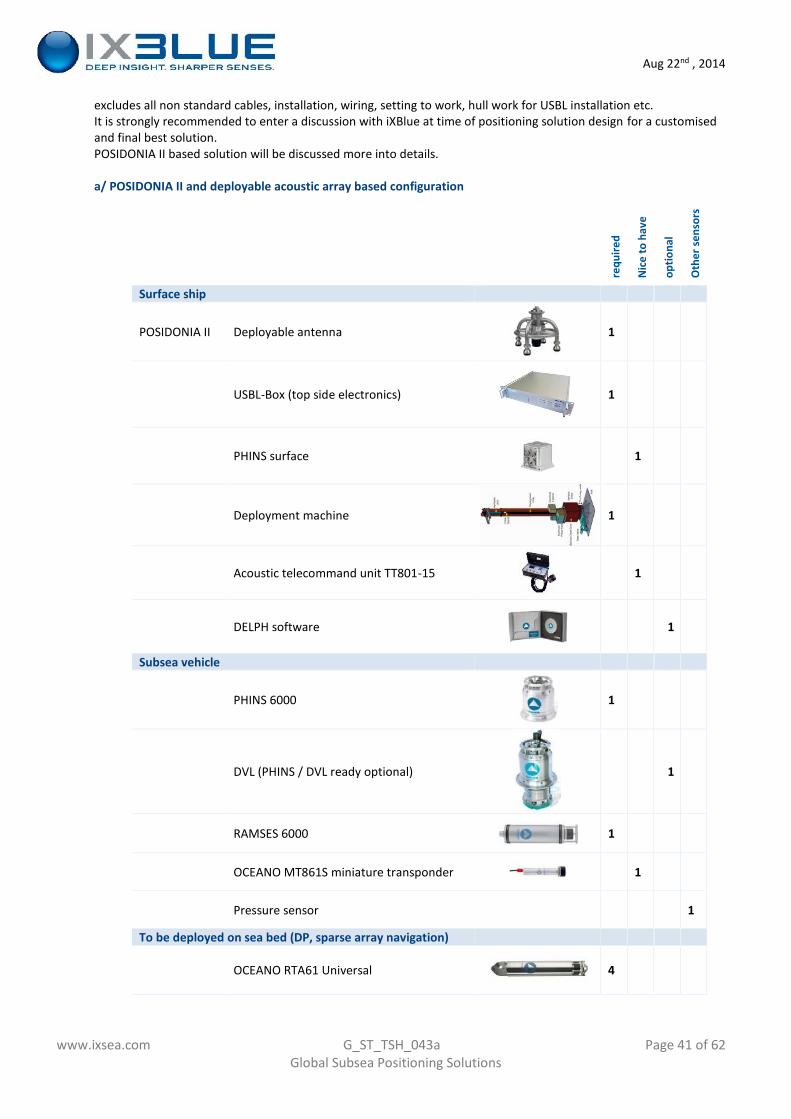
Aug 22nd , 2014
www.ixsea.com G_ST_TSH_043a Page 41 of 62Global Subsea Positioning Solutions
excludes all non standard cables, installation, wiring, setting to work, hull work for USBL installation etc.It is strongly recommended to enter a discussion with iXBlue at time of positioning solution design for a customisedand final best solution.POSIDONIA II based solution will be discussed more into details.
a/ POSIDONIA II and deployable acoustic array based configuration
requ
ired
Nic
e to
hav
e
optio
nal
Oth
er se
nsor
s
Surface ship
POSIDONIA II Deployable antenna 1
USBL-Box (top side electronics) 1
PHINS surface 1
Deployment machine 1
Acoustic telecommand unit TT801-15 1
DELPH software 1
Subsea vehicle
PHINS 6000 1
DVL (PHINS / DVL ready optional) 1
RAMSES 6000 1
OCEANO MT861S miniature transponder 1
Pressure sensor 1
To be deployed on sea bed (DP, sparse array navigation)
OCEANO RTA61 Universal 4
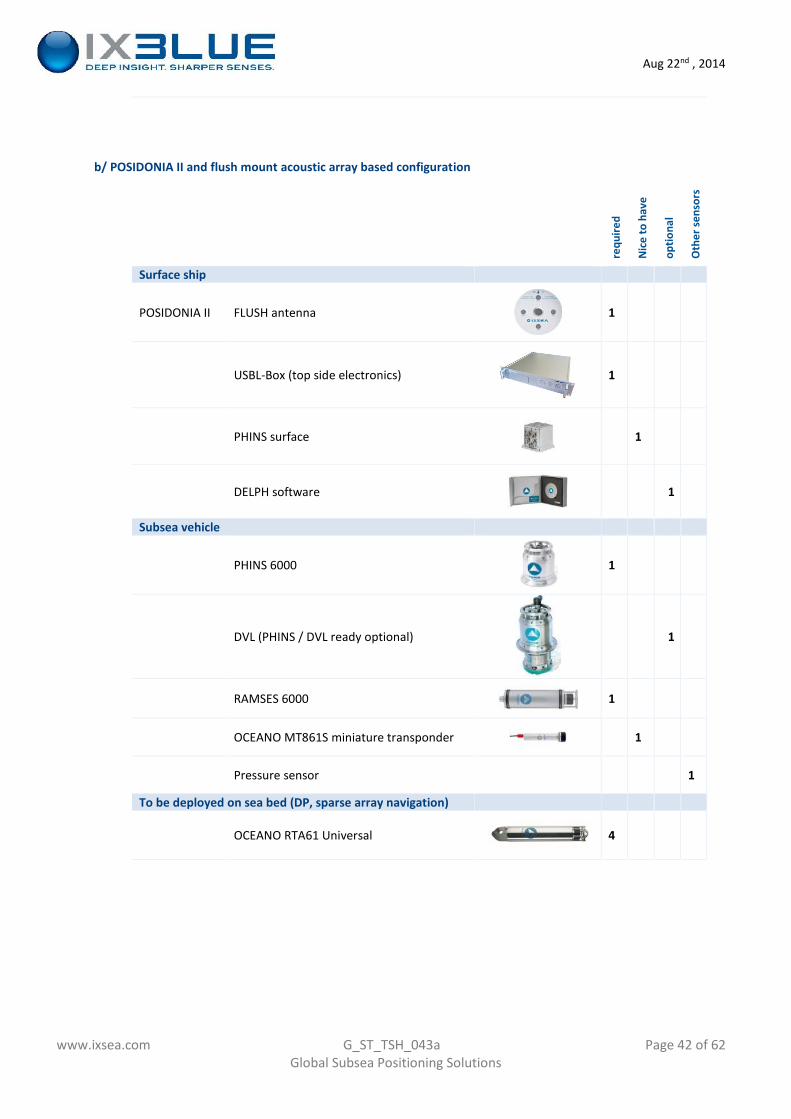
Aug 22nd , 2014
www.ixsea.com G_ST_TSH_043a Page 42 of 62Global Subsea Positioning Solutions
b/ POSIDONIA II and flush mount acoustic array based configuration
requ
ired
Nic
e to
hav
e
optio
nal
Oth
er se
nsor
s
Surface ship
POSIDONIA II FLUSH antenna 1
USBL-Box (top side electronics) 1
PHINS surface 1
DELPH software 1
Subsea vehicle
PHINS 6000 1
DVL (PHINS / DVL ready optional) 1
RAMSES 6000 1
OCEANO MT861S miniature transponder 1
Pressure sensor 1
To be deployed on sea bed (DP, sparse array navigation)
OCEANO RTA61 Universal 4
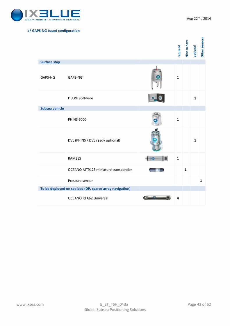
Aug 22nd , 2014
www.ixsea.com G_ST_TSH_043a Page 43 of 62Global Subsea Positioning Solutions
b/ GAPS-NG based configuration
requ
ired
Nic
e to
hav
e
optio
nal
Oth
er se
nsor
s
Surface ship
GAPS-NG GAPS-NG 1
DELPH software 1
Subsea vehicle
PHINS 6000 1
DVL (PHINS / DVL ready optional) 1
RAMSES 1
OCEANO MT912S miniature transponder 1
Pressure sensor 1
To be deployed on sea bed (DP, sparse array navigation)
OCEANO RTA62 Universal 4
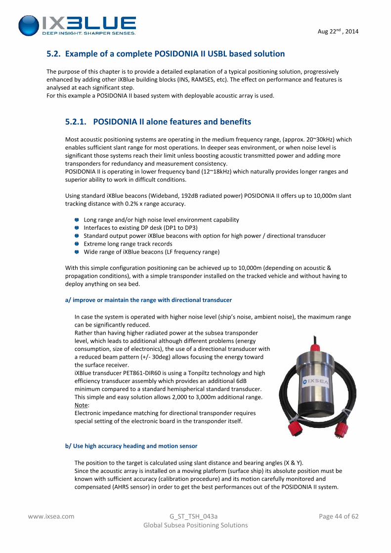
Aug 22nd , 2014
www.ixsea.com G_ST_TSH_043a Page 44 of 62Global Subsea Positioning Solutions
5.2. Example of a complete POSIDONIA II USBL based solution
The purpose of this chapter is to provide a detailed explanation of a typical positioning solution, progressivelyenhanced by adding other iXBlue building blocks (INS, RAMSES, etc). The effect on performance and features isanalysed at each significant step.For this example a POSIDONIA II based system with deployable acoustic array is used.
5.2.1. POSIDONIA II alone features and benefits
Most acoustic positioning systems are operating in the medium frequency range, (approx. 20~30kHz) whichenables sufficient slant range for most operations. In deeper seas environment, or when noise level issignificant those systems reach their limit unless boosting acoustic transmitted power and adding moretransponders for redundancy and measurement consistency.POSIDONIA II is operating in lower frequency band (12~18kHz) which naturally provides longer ranges andsuperior ability to work in difficult conditions.
Using standard iXBlue beacons (Wideband, 192dB radiated power) POSIDONIA II offers up to 10,000m slanttracking distance with 0.2% x range accuracy.
Long range and/or high noise level environment capabilityInterfaces to existing DP desk (DP1 to DP3)Standard output power iXBlue beacons with option for high power / directional transducerExtreme long range track recordsWide range of iXBlue beacons (LF frequency range)
With this simple configuration positioning can be achieved up to 10,000m (depending on acoustic &propagation conditions), with a simple transponder installed on the tracked vehicle and without having todeploy anything on sea bed.
a/ improve or maintain the range with directional transducer
In case the system is operated with higher noise level (ship’s noise, ambient noise), the maximum rangecan be significantly reduced.Rather than having higher radiated power at the subsea transponderlevel, which leads to additional although different problems (energyconsumption, size of electronics), the use of a directional transducer witha reduced beam pattern (+/- 30deg) allows focusing the energy towardthe surface receiver.iXBlue transducer PET861-DIR60 is using a Tonpiltz technology and highefficiency transducer assembly which provides an additional 6dBminimum compared to a standard hemispherical standard transducer.This simple and easy solution allows 2,000 to 3,000m additional range.Note:Electronic impedance matching for directional transponder requiresspecial setting of the electronic board in the transponder itself.
b/ Use high accuracy heading and motion sensor
The position to the target is calculated using slant distance and bearing angles (X & Y).Since the acoustic array is installed on a moving platform (surface ship) its absolute position must beknown with sufficient accuracy (calibration procedure) and its motion carefully monitored andcompensated (AHRS sensor) in order to get the best performances out of the POSIDONIA II system.
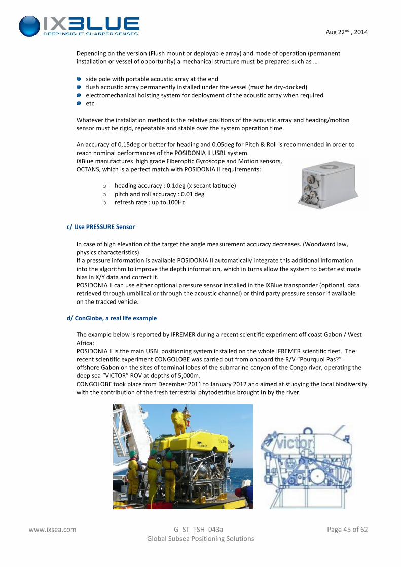
Aug 22nd , 2014
www.ixsea.com G_ST_TSH_043a Page 45 of 62Global Subsea Positioning Solutions
Depending on the version (Flush mount or deployable array) and mode of operation (permanentinstallation or vessel of opportunity) a mechanical structure must be prepared such as …
side pole with portable acoustic array at the endflush acoustic array permanently installed under the vessel (must be dry-docked)electromechanical hoisting system for deployment of the acoustic array when requiredetc
Whatever the installation method is the relative positions of the acoustic array and heading/motionsensor must be rigid, repeatable and stable over the system operation time.
An accuracy of 0,15deg or better for heading and 0.05deg for Pitch & Roll is recommended in order toreach nominal performances of the POSIDONIA II USBL system.iXBlue manufactures high grade Fiberoptic Gyroscope and Motion sensors,OCTANS, which is a perfect match with POSIDONIA II requirements:
o heading accuracy : 0.1deg (x secant latitude)o pitch and roll accuracy : 0.01 dego refresh rate : up to 100Hz
c/ Use PRESSURE Sensor
In case of high elevation of the target the angle measurement accuracy decreases. (Woodward law,physics characteristics)If a pressure information is available POSIDONIA II automatically integrate this additional informationinto the algorithm to improve the depth information, which in turns allow the system to better estimatebias in X/Y data and correct it.POSIDONIA II can use either optional pressure sensor installed in the iXBlue transponder (optional, dataretrieved through umbilical or through the acoustic channel) or third party pressure sensor if availableon the tracked vehicle.
d/ ConGlobe, a real life example
The example below is reported by IFREMER during a recent scientific experiment off coast Gabon / WestAfrica:POSIDONIA II is the main USBL positioning system installed on the whole IFREMER scientific fleet. Therecent scientific experiment CONGOLOBE was carried out from onboard the R/V “Pourquoi Pas?”offshore Gabon on the sites of terminal lobes of the submarine canyon of the Congo river, operating thedeep sea “VICTOR” ROV at depths of 5,000m.CONGOLOBE took place from December 2011 to January 2012 and aimed at studying the local biodiversitywith the contribution of the fresh terrestrial phytodetritus brought in by the river.
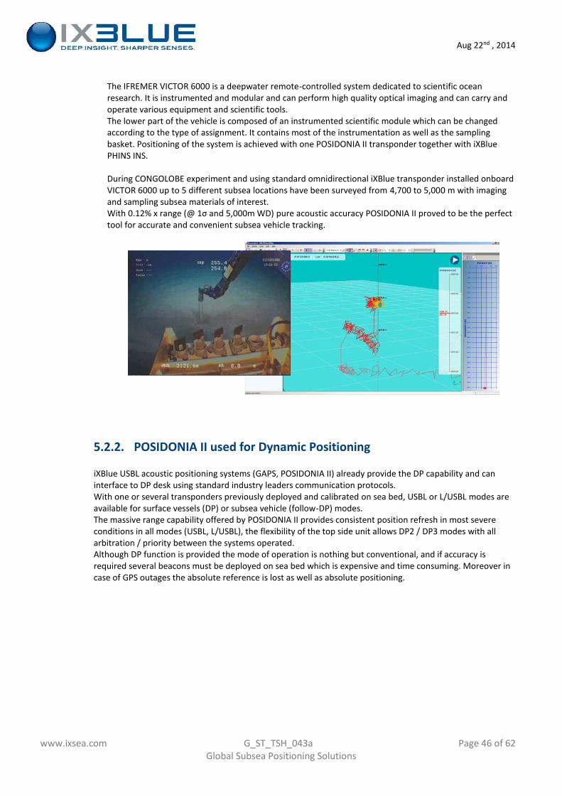
Aug 22nd , 2014
www.ixsea.com G_ST_TSH_043a Page 46 of 62Global Subsea Positioning Solutions
The IFREMER VICTOR 6000 is a deepwater remote-controlled system dedicated to scientific oceanresearch. It is instrumented and modular and can perform high quality optical imaging and can carry andoperate various equipment and scientific tools.The lower part of the vehicle is composed of an instrumented scientific module which can be changedaccording to the type of assignment. It contains most of the instrumentation as well as the samplingbasket. Positioning of the system is achieved with one POSIDONIA II transponder together with iXBluePHINS INS.
During CONGOLOBE experiment and using standard omnidirectional iXBlue transponder installed onboardVICTOR 6000 up to 5 different subsea locations have been surveyed from 4,700 to 5,000 m with imagingand sampling subsea materials of interest.With 0.12% x range (@ 1σ and 5,000m WD) pure acoustic accuracy POSIDONIA II proved to be the perfecttool for accurate and convenient subsea vehicle tracking.
5.2.2. POSIDONIA II used for Dynamic Positioning
iXBlue USBL acoustic positioning systems (GAPS, POSIDONIA II) already provide the DP capability and caninterface to DP desk using standard industry leaders communication protocols.With one or several transponders previously deployed and calibrated on sea bed, USBL or L/USBL modes areavailable for surface vessels (DP) or subsea vehicle (follow-DP) modes.The massive range capability offered by POSIDONIA II provides consistent position refresh in most severeconditions in all modes (USBL, L/USBL), the flexibility of the top side unit allows DP2 / DP3 modes with allarbitration / priority between the systems operated.Although DP function is provided the mode of operation is nothing but conventional, and if accuracy isrequired several beacons must be deployed on sea bed which is expensive and time consuming. Moreover incase of GPS outages the absolute reference is lost as well as absolute positioning.
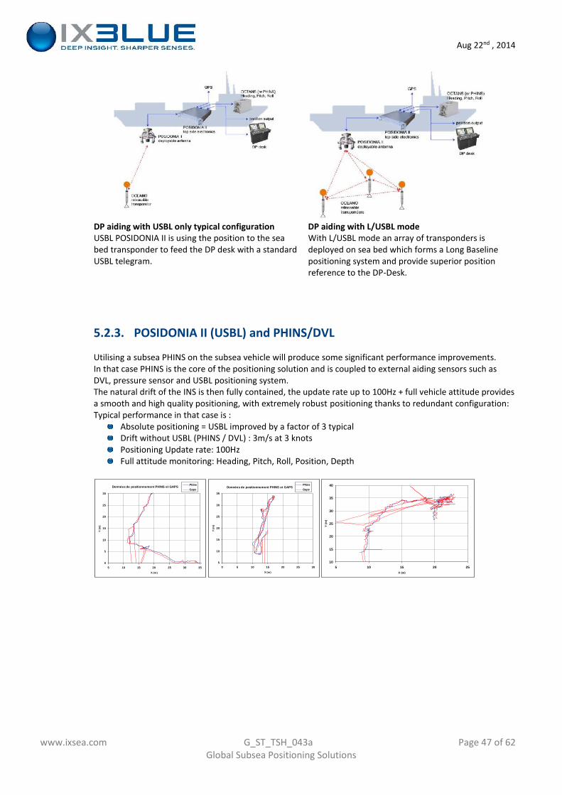
Aug 22nd , 2014
www.ixsea.com G_ST_TSH_043a Page 47 of 62Global Subsea Positioning Solutions
DP aiding with USBL only typical configurationUSBL POSIDONIA II is using the position to the seabed transponder to feed the DP desk with a standardUSBL telegram.
DP aiding with L/USBL modeWith L/USBL mode an array of transponders isdeployed on sea bed which forms a Long Baselinepositioning system and provide superior positionreference to the DP-Desk.
5.2.3. POSIDONIA II (USBL) and PHINS/DVL
Utilising a subsea PHINS on the subsea vehicle will produce some significant performance improvements.In that case PHINS is the core of the positioning solution and is coupled to external aiding sensors such asDVL, pressure sensor and USBL positioning system.The natural drift of the INS is then fully contained, the update rate up to 100Hz + full vehicle attitude providesa smooth and high quality positioning, with extremely robust positioning thanks to redundant configuration:Typical performance in that case is :
Absolute positioning = USBL improved by a factor of 3 typicalDrift without USBL (PHINS / DVL) : 3m/s at 3 knotsPositioning Update rate: 100HzFull attitude monitoring: Heading, Pitch, Roll, Position, Depth
Données de positionnement PHINS et GAPS
0
5
10
15
20
25
30
5 10 15 20 25 30 35
X (m)
Y (m
)
PhinsGaps
Données de positionnement PHINS et GAPS
5
10
15
20
25
30
35
0 5 10 15 20 25 30
X (m)
Y (m
)
PhinsGaps
10
15
20
25
30
35
40
5 10 15 20 25X (m)
Y (m
)
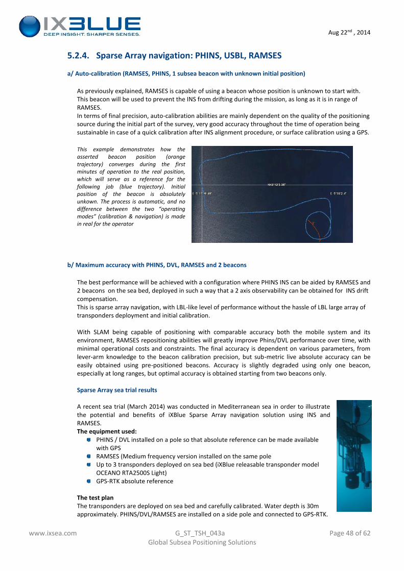
Aug 22nd , 2014
www.ixsea.com G_ST_TSH_043a Page 48 of 62Global Subsea Positioning Solutions
5.2.4. Sparse Array navigation: PHINS, USBL, RAMSES
a/ Auto-calibration (RAMSES, PHINS, 1 subsea beacon with unknown initial position)
As previously explained, RAMSES is capable of using a beacon whose position is unknown to start with.This beacon will be used to prevent the INS from drifting during the mission, as long as it is in range ofRAMSES.In terms of final precision, auto-calibration abilities are mainly dependent on the quality of the positioningsource during the initial part of the survey, very good accuracy throughout the time of operation beingsustainable in case of a quick calibration after INS alignment procedure, or surface calibration using a GPS.
This example demonstrates how theasserted beacon position (orangetrajectory) converges during the firstminutes of operation to the real position,which will serve as a reference for thefollowing job (blue trajectory). Initialposition of the beacon is absolutelyunkown. The process is automatic, and nodifference between the two “operatingmodes” (calibration & navigation) is madein real for the operator
b/ Maximum accuracy with PHINS, DVL, RAMSES and 2 beacons
The best performance will be achieved with a configuration where PHINS INS can be aided by RAMSES and2 beacons on the sea bed, deployed in such a way that a 2 axis observability can be obtained for INS driftcompensation.This is sparse array navigation, with LBL-like level of performance without the hassle of LBL large array oftransponders deployment and initial calibration.
With SLAM being capable of positioning with comparable accuracy both the mobile system and itsenvironment, RAMSES repositioning abilities will greatly improve Phins/DVL performance over time, withminimal operational costs and constraints. The final accuracy is dependent on various parameters, fromlever-arm knowledge to the beacon calibration precision, but sub-metric live absolute accuracy can beeasily obtained using pre-positioned beacons. Accuracy is slightly degraded using only one beacon,especially at long ranges, but optimal accuracy is obtained starting from two beacons only.
Sparse Array sea trial results
A recent sea trial (March 2014) was conducted in Mediterranean sea in order to illustratethe potential and benefits of iXBlue Sparse Array navigation solution using INS andRAMSES.The equipment used:
PHINS / DVL installed on a pole so that absolute reference can be made availablewith GPSRAMSES (Medium frequency version installed on the same poleUp to 3 transponders deployed on sea bed (iXBlue releasable transponder modelOCEANO RTA2500S Light)GPS-RTK absolute reference
The test planThe transponders are deployed on sea bed and carefully calibrated. Water depth is 30mapproximately. PHINS/DVL/RAMSES are installed on a side pole and connected to GPS-RTK.
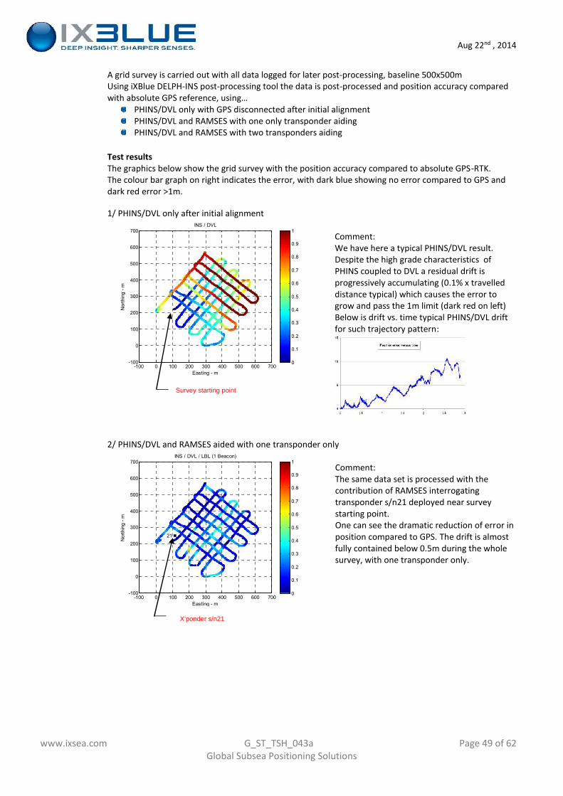
Aug 22nd , 2014
www.ixsea.com G_ST_TSH_043a Page 49 of 62Global Subsea Positioning Solutions
A grid survey is carried out with all data logged for later post-processing, baseline 500x500mUsing iXBlue DELPH-INS post-processing tool the data is post-processed and position accuracy comparedwith absolute GPS reference, using…
PHINS/DVL only with GPS disconnected after initial alignmentPHINS/DVL and RAMSES with one only transponder aidingPHINS/DVL and RAMSES with two transponders aiding
Test resultsThe graphics below show the grid survey with the position accuracy compared to absolute GPS-RTK.The colour bar graph on right indicates the error, with dark blue showing no error compared to GPS anddark red error >1m.
1/ PHINS/DVL only after initial alignment
Comment:We have here a typical PHINS/DVL result.Despite the high grade characteristics ofPHINS coupled to DVL a residual drift isprogressively accumulating (0.1% x travelleddistance typical) which causes the error togrow and pass the 1m limit (dark red on left)Below is drift vs. time typical PHINS/DVL driftfor such trajectory pattern:
2/ PHINS/DVL and RAMSES aided with one transponder only
Comment:The same data set is processed with thecontribution of RAMSES interrogatingtransponder s/n21 deployed near surveystarting point.One can see the dramatic reduction of error inposition compared to GPS. The drift is almostfully contained below 0.5m during the wholesurvey, with one transponder only.
21
Nor
thin
g - m
Easting - m
INS / DVL / LBL (1 Beacon)
-100 0 100 200 300 400 500 600 700-100
0
100
200
300
400
500
600
700
0
0.1
0.2
0.3
0.4
0.5
0.6
0.7
0.8
0.9
1
Nor
thin
g - m
Easting - m
INS / DVL
-100 0 100 200 300 400 500 600 700-100
0
100
200
300
400
500
600
700
0
0.1
0.2
0.3
0.4
0.5
0.6
0.7
0.8
0.9
1
Survey starting point
X’ponder s/n21
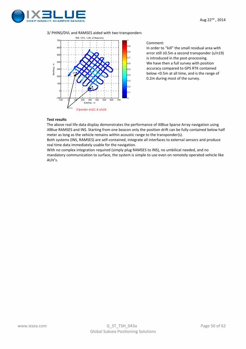
Aug 22nd , 2014
www.ixsea.com G_ST_TSH_043a Page 50 of 62Global Subsea Positioning Solutions
3/ PHINS/DVL and RAMSES aided with two transponders
Comment:In order to “kill” the small residual area witherror still ≥0.5m a second transponder (s/n19)is introduced in the post-processing.We have then a full survey with positionaccuracy compared to GPS RTK containedbelow <0.5m at all time, and is the range of0.2m during most of the survey.
Test resultsThe above real life data display demonstrates the performance of iXBlue Sparse Array navigation usingiXBlue RAMSES and INS. Starting from one beacon only the position drift can be fully contained below halfmeter as long as the vehicle remains within acoustic range to the transponder(s).Both systems (INS, RAMSES) are self-contained, integrate all interfaces to external sensors and producereal time data immediately usable for the navigation.With no complex integration required (simply plug RAMSES to INS), no umbilical needed, and nomandatory communication to surface, the system is simple to use even on remotely operated vehicle likeAUV’s.
19
21
Nor
thin
g - m
Easting - m
INS / DVL / LBL (2 Beacons)
-100 0 100 200 300 400 500 600 700-100
0
100
200
300
400
500
600
700
0
0.1
0.2
0.3
0.4
0.5
0.6
0.7
0.8
0.9
1
X’ponder s/n21 & s/n19
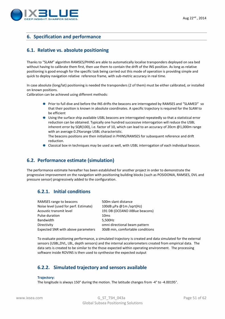
Aug 22nd , 2014
www.ixsea.com G_ST_TSH_043a Page 51 of 62Global Subsea Positioning Solutions
6. Specification and performance
6.1. Relative vs. absolute positioning
Thanks to “SLAM” algorithm RAMSES/PHINS are able to automatically localise transponders deployed on sea bedwithout having to calibrate them first, then use them to contain the drift of the INS position. As long as relativepositioning is good enough for the specific task being carried out this mode of operation is providing simple andquick to deploy navigation relative reference frame, with sub-metric accuracy in real time.
In case absolute (long/lat) positioning is needed the transponders (2 of them) must be either calibrated, or installedon known positions.Calibration can be achieved using different methods:
Prior to full dive and before the INS drifts the beacons are interrogated by RAMSES and “SLAMED” sothat their position is known in absolute coordinates. A specific trajectory is required for the SLAM tobe efficientUsing the surface ship available USBL beacons are interrogated repeatedly so that a statistical errorreduction can be obtained. Typically one hundred successive interrogation will reduce the USBLinherent error by SQR(100), i.e. factor of 10, which can lead to an accuracy of 20cm @1,000m rangewith an average 0.2%xrange USBL characteristic.The beacons positions are then initialized in PHINS/RAMSES for subsequent reference and driftreduction.Classical box-in techniques may be used as well, with USBL interrogation of each individual beacon.
6.2. Performance estimate (simulation)
The performance estimate hereafter has been established for another project in order to demonstrate theprogressive improvement on the navigation with positioning building blocks (such as POSIDONIA, RAMSES, DVL andpressure sensor) progressively added to the configuration.
6.2.1. Initial conditions
RAMSES range to beacons 500m slant distanceNoise level (used for perf. Estimate) 100dB µPa @1m /sqrt(Hz)Acoustic transmit level 191 DB (OCEANO iXBlue beacons)Pulse duration 10msBandwidth 5,500HzDirectivity omni directional beam patternExpected SNR with above parameters 30dB min, comfortable conditions
To evaluate positioning performance, a simulated trajectory is created and data simulated for the externalsensors (USBL,DVL, LBL, depth sensors) and the internal accelerometers created from empirical data. Thedata sets is created to be similar to the those expected within operating environment. The processingsoftware inside ROVINS is then used to synthesise the expected output
6.2.2. Simulated trajectory and sensors available
Trajectory:The longitude is always 150° during the motion. The latitude changes from -4° to -4.00195°.
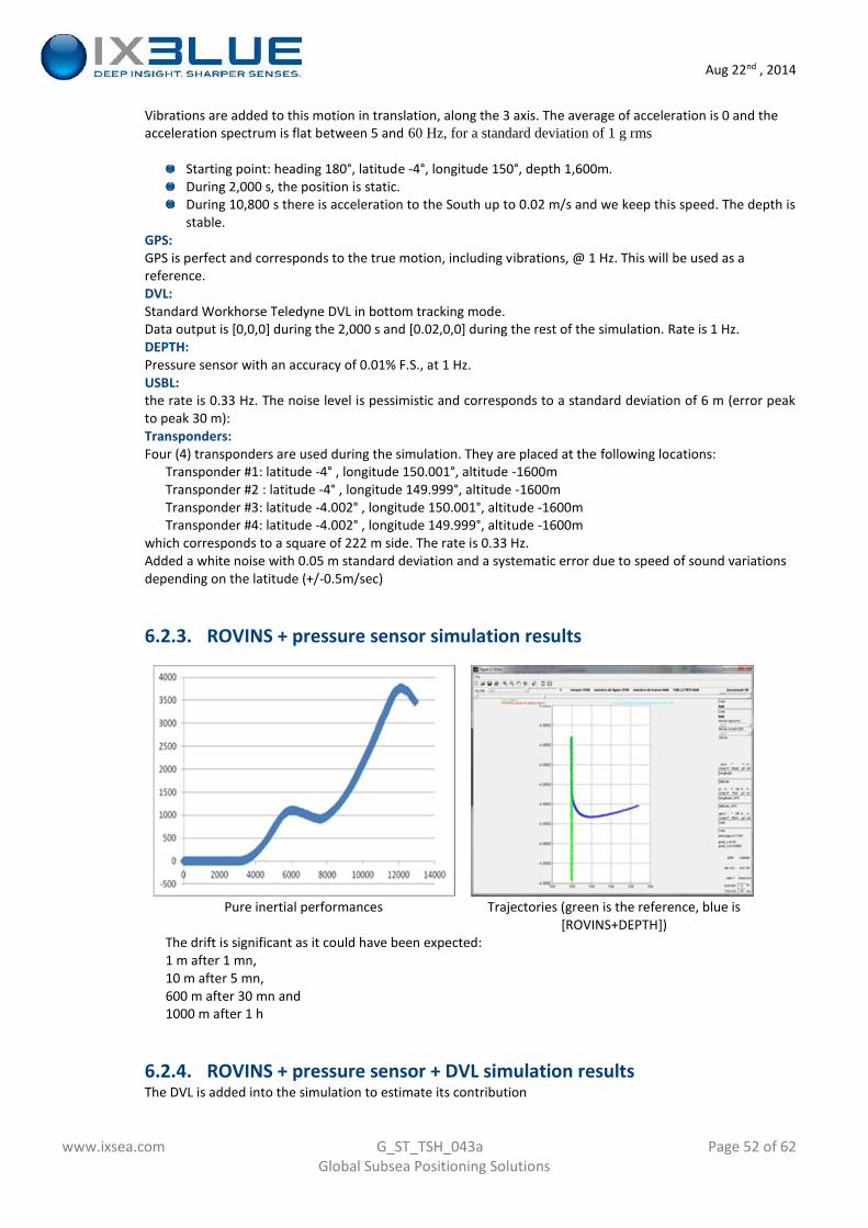
Aug 22nd , 2014
www.ixsea.com G_ST_TSH_043a Page 52 of 62Global Subsea Positioning Solutions
Vibrations are added to this motion in translation, along the 3 axis. The average of acceleration is 0 and theacceleration spectrum is flat between 5 and 60 Hz, for a standard deviation of 1 g rms
Starting point: heading 180°, latitude -4°, longitude 150°, depth 1,600m.During 2,000 s, the position is static.During 10,800 s there is acceleration to the South up to 0.02 m/s and we keep this speed. The depth isstable.
GPS:GPS is perfect and corresponds to the true motion, including vibrations, @ 1 Hz. This will be used as areference.DVL:Standard Workhorse Teledyne DVL in bottom tracking mode.Data output is [0,0,0] during the 2,000 s and [0.02,0,0] during the rest of the simulation. Rate is 1 Hz.DEPTH:Pressure sensor with an accuracy of 0.01% F.S., at 1 Hz.USBL:the rate is 0.33 Hz. The noise level is pessimistic and corresponds to a standard deviation of 6 m (error peakto peak 30 m):Transponders:Four (4) transponders are used during the simulation. They are placed at the following locations:
Transponder #1: latitude -4° , longitude 150.001°, altitude -1600mTransponder #2 : latitude -4° , longitude 149.999°, altitude -1600mTransponder #3: latitude -4.002° , longitude 150.001°, altitude -1600mTransponder #4: latitude -4.002° , longitude 149.999°, altitude -1600m
which corresponds to a square of 222 m side. The rate is 0.33 Hz.Added a white noise with 0.05 m standard deviation and a systematic error due to speed of sound variationsdepending on the latitude (+/-0.5m/sec)
6.2.3. ROVINS + pressure sensor simulation results
Pure inertial performances Trajectories (green is the reference, blue is[ROVINS+DEPTH])
The drift is significant as it could have been expected:1 m after 1 mn,10 m after 5 mn,600 m after 30 mn and1000 m after 1 h
6.2.4. ROVINS + pressure sensor + DVL simulation resultsThe DVL is added into the simulation to estimate its contribution
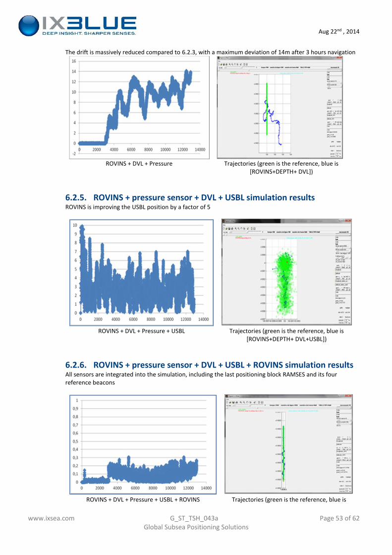
Aug 22nd , 2014
www.ixsea.com G_ST_TSH_043a Page 53 of 62Global Subsea Positioning Solutions
The drift is massively reduced compared to 6.2.3, with a maximum deviation of 14m after 3 hours navigation
ROVINS + DVL + Pressure Trajectories (green is the reference, blue is[ROVINS+DEPTH+ DVL])
6.2.5. ROVINS + pressure sensor + DVL + USBL simulation resultsROVINS is improving the USBL position by a factor of 5
ROVINS + DVL + Pressure + USBL Trajectories (green is the reference, blue is[ROVINS+DEPTH+ DVL+USBL])
6.2.6. ROVINS + pressure sensor + DVL + USBL + ROVINS simulation resultsAll sensors are integrated into the simulation, including the last positioning block RAMSES and its fourreference beacons
ROVINS + DVL + Pressure + USBL + ROVINS Trajectories (green is the reference, blue is
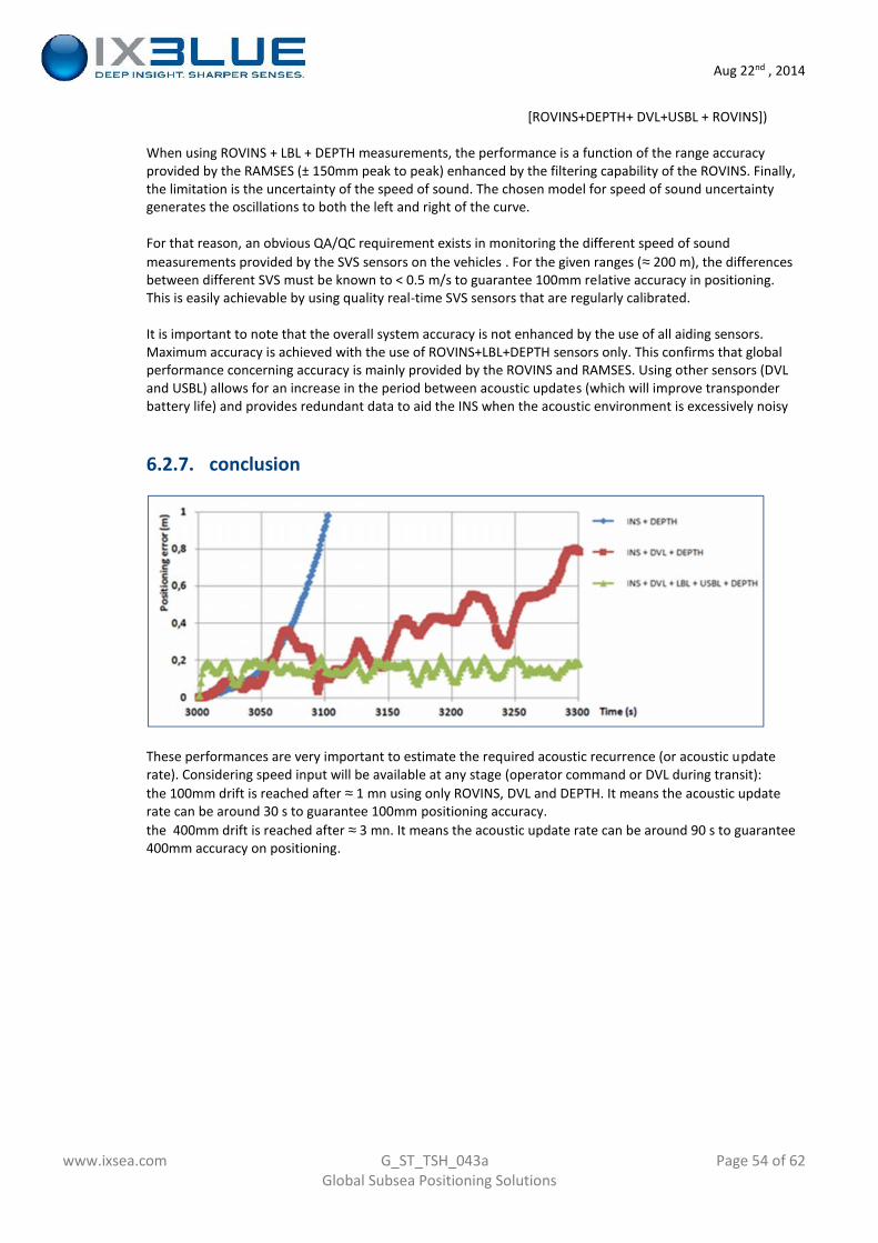
Aug 22nd , 2014
www.ixsea.com G_ST_TSH_043a Page 54 of 62Global Subsea Positioning Solutions
[ROVINS+DEPTH+ DVL+USBL + ROVINS])
When using ROVINS + LBL + DEPTH measurements, the performance is a function of the range accuracyprovided by the RAMSES (± 150mm peak to peak) enhanced by the filtering capability of the ROVINS. Finally,the limitation is the uncertainty of the speed of sound. The chosen model for speed of sound uncertaintygenerates the oscillations to both the left and right of the curve.
For that reason, an obvious QA/QC requirement exists in monitoring the different speed of soundmeasurements provided by the SVS sensors on the vehicles . For the given ranges ( 200 m), the differencesbetween different SVS must be known to < 0.5 m/s to guarantee 100mm relative accuracy in positioning.This is easily achievable by using quality real-time SVS sensors that are regularly calibrated.
It is important to note that the overall system accuracy is not enhanced by the use of all aiding sensors.Maximum accuracy is achieved with the use of ROVINS+LBL+DEPTH sensors only. This confirms that globalperformance concerning accuracy is mainly provided by the ROVINS and RAMSES. Using other sensors (DVLand USBL) allows for an increase in the period between acoustic updates (which will improve transponderbattery life) and provides redundant data to aid the INS when the acoustic environment is excessively noisy
6.2.7. conclusion
These performances are very important to estimate the required acoustic recurrence (or acoustic updaterate). Considering speed input will be available at any stage (operator command or DVL during transit):the 100mm drift is reached after 1 mn using only ROVINS, DVL and DEPTH. It means the acoustic updaterate can be around 30 s to guarantee 100mm positioning accuracy.the 400mm drift is reached after 3 mn. It means the acoustic update rate can be around 90 s to guarantee400mm accuracy on positioning.
Aug 22nd , 2014
www.ixsea.com G_ST_TSH_043a Page 55 of 62Global Subsea Positioning Solutions
7. Benefits, References
7.1. Advantages of the proposed solution
A modular approachThe iXBlue solution is based on a modular approach. The user can decide which equipment andarchitecture he wants to use, based on his needs for a dedicated application. It can be USBL only, orINS+USBL, INS+LBL sparse array also.Notably a full LBL network is not required, as it is possible to deploy only a LBL spare array, whichmeans an improved productivity and reduced operational costs.
A state-of-the-art solution with INS and data fusionThe proposed solution is not only the up-to-date approach for subsea positioning, it is also based onstate-of-the-art equipment and system architecture allowing all operational functionalities: Unrivalled position recurrence (100 Hz with INS option) mobile positioning solution with USBL+INS (saving of time and yet a very good accuracy) high accuracy positioning with INS + LBL spare array (enhanced accuracy since the INS filters LBL
noise) robustness against GPS dropouts and noise on one hand, plus robustness against acoustic
positioning dropouts and noise on the other hand, thanks to INS. a combination of all those advantages when using altogether the equipment thanks to data
fusion.
Operational cost savingsThe integrated underwater positioning system allows significant cost savings due to reducedmobilization time, not only in its USBL+INS configuration, but also when using the LBL Sparse Arrayfeature due to savings in deployment and recovery: the LBL Sparse Array does not require to have thefull LBL network deployed to be operational. Already starting from 1 single beacon deployed theaccuracy is improved, 3 is the optimum.
An upgradeable systemState-of-the-art positioning systems are based on acoustic positioning, inertial systems, data fusion...For each of those technologies, iXBlue belongs to the rare companies which are really highly qualified.But more importantly, iXBlue is the only company whose expertise embraces this whole spectrum.
An open systemUnlike other systems, the solution proposed by iXBlue is open, meaning it can be interfaced with thirdparty equipment..
Direction and attitude of the vehiclePHINS provides the full attitude of the subsea vehicle (heading, roll and pitch) with an extremeaccuracy.
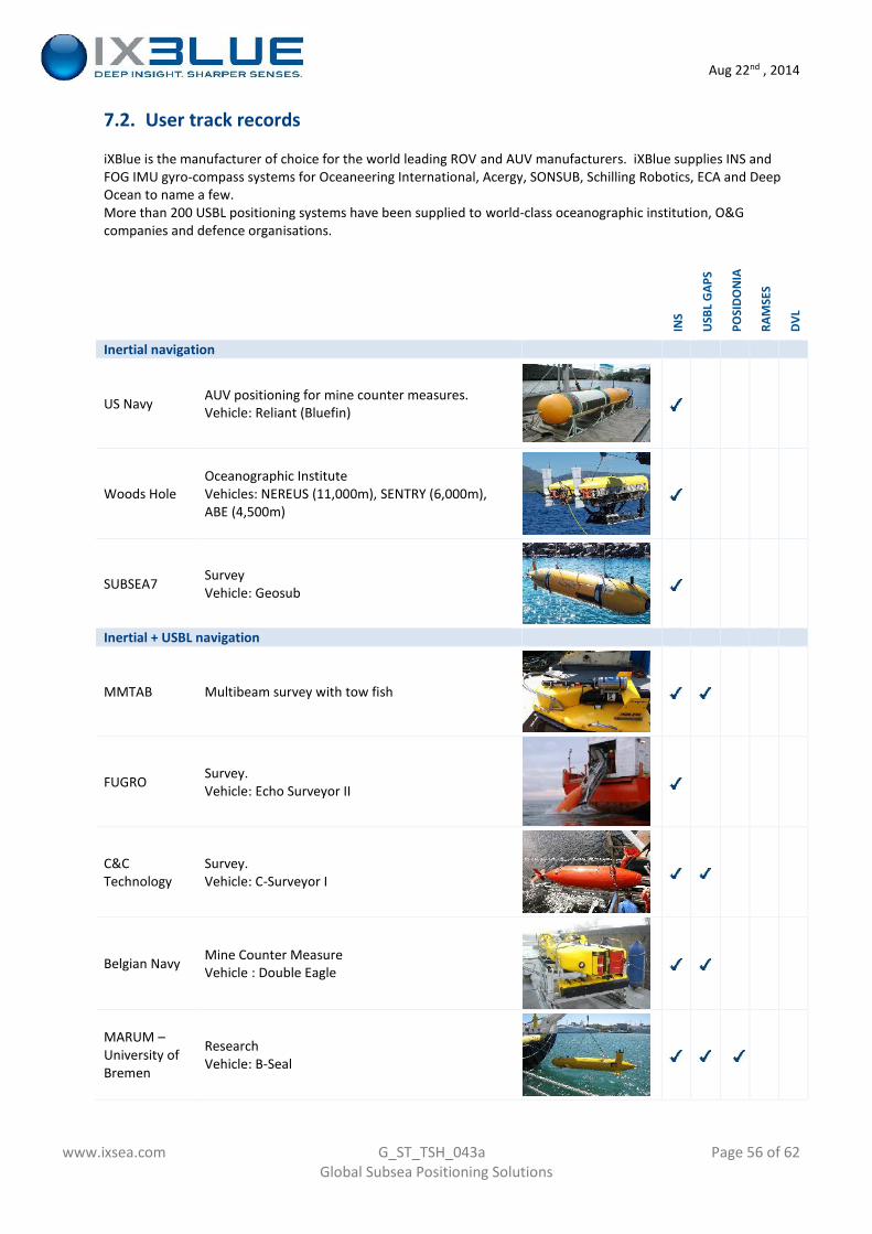
Aug 22nd , 2014
www.ixsea.com G_ST_TSH_043a Page 56 of 62Global Subsea Positioning Solutions
7.2. User track records
iXBlue is the manufacturer of choice for the world leading ROV and AUV manufacturers. iXBlue supplies INS andFOG IMU gyro-compass systems for Oceaneering International, Acergy, SONSUB, Schilling Robotics, ECA and DeepOcean to name a few.More than 200 USBL positioning systems have been supplied to world-class oceanographic institution, O&Gcompanies and defence organisations.
INS
USB
L G
APS
POSI
DON
IA
RAM
SES
DVL
Inertial navigation
US Navy AUV positioning for mine counter measures.Vehicle: Reliant (Bluefin)
Woods HoleOceanographic InstituteVehicles: NEREUS (11,000m), SENTRY (6,000m),ABE (4,500m)
SUBSEA7 SurveyVehicle: Geosub
Inertial + USBL navigation
MMTAB Multibeam survey with tow fish
FUGRO Survey.Vehicle: Echo Surveyor II
C&CTechnology
Survey.Vehicle: C-Surveyor I
Belgian Navy Mine Counter MeasureVehicle : Double Eagle
MARUM –University ofBremen
ResearchVehicle: B-Seal
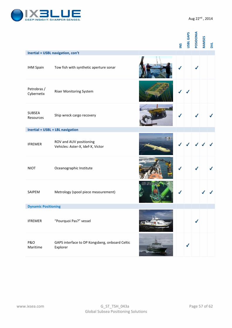
Aug 22nd , 2014
www.ixsea.com G_ST_TSH_043a Page 57 of 62Global Subsea Positioning Solutions
INS
USB
L G
APS
POSI
DON
IA
RAM
SES
DVL
Inertial + USBL navigation, con’t
IHM Spain Tow fish with synthetic aperture sonar
Petrobras /Cybernetix Riser Monitoring System
SUBSEAResources Ship wreck cargo recovery
Inertial + USBL + LBL navigation
IFREMER ROV and AUV positioningVehicles: Aster-X, Idef-X, Victor
NIOT Oceanographic Institute
SAIPEM Metrology (spool piece measurement)
Dynamic Positioning
IFREMER “Pourquoi Pas?” vessel
P&OMaritime
GAPS interface to DP Kongsberg, onboard CelticExplorer
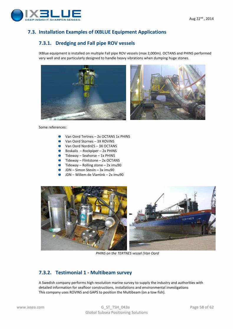
Aug 22nd , 2014
www.ixsea.com G_ST_TSH_043a Page 58 of 62Global Subsea Positioning Solutions
7.3. Installation Examples of IXBLUE Equipment Applications
7.3.1. Dredging and Fall pipe ROV vessels
iXBlue equipment is installed on multiple Fall pipe ROV vessels (max 2,000m). OCTANS and PHINS performedvery well and are particularly designed to handle heavy vibrations when dumping huge stones.
Some references:
Van Oord Tertnes – 2x OCTANS 1x PHINSVan Oord Stornes – 3X ROVINSVan Oord NordnES – 3X OCTANSBoskalis – Rockpiper – 2x PHINSTideway – Seahorse – 1x PHINSTideway – Flintstone – 2x OCTANSTideway – Rolling stone – 2x imu90JDN – Simon Stevin – 3x imu90JDN – Willem de Vlamink – 2x imu90
PHINS on the TERTNES vessel (Van Oord
7.3.2. Testimonial 1 - Multibeam survey
A Swedish company performs high resolution marine survey to supply the industry and authorities withdetailed information for seafloor constructions, installations and environmental investigationsThis company uses ROVINS and GAPS to position the Multibeam (on a tow fish).
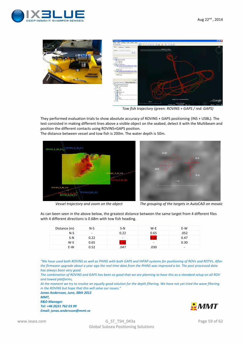
Aug 22nd , 2014
www.ixsea.com G_ST_TSH_043a Page 59 of 62Global Subsea Positioning Solutions
Tow fish trajectory (green: ROVINS + GAPS / red: GAPS)
They performed evaluation trials to show absolute accuracy of ROVINS + GAPS positioning (INS + USBL). Thetest consisted in making different lines above a visible object on the seabed, detect it with the Multibeam andposition the different contacts using ROVINS+GAPS position.The distance between vessel and tow fish is 200m. The water depth is 50m.
Vessel trajectory and zoom on the object The grouping of the targets in AutoCAD on mosaic
As can been seen in the above below, the greatest distance between the same target from 4 different fileswith 4 different directions is 0.68m with tow fish heading.
Distance (m) N-S S-N W-E E-WN-S - 0.22 0.65 .052S-N 0.22 - 0.68 0.47
W-E 0.65 0.68 - 0.30E-W 0.52 .047 .030 -
“We have used both ROVINS as well as PHINS with both GAPS and HiPAP systems for positioning of ROVs and ROTVs. Afterthe firmware upgrade about a year ago the real time data from the PHINS was improved a lot. The post processed datahas always been very good.The combination of ROVINS and GAPS has been so good that we are planning to have this as a standard setup on all ROVand towed platforms,At the moment we try to resolve an equally good solution for the depth filtering. We have not yet tried the wave filteringin the ROVINS but hope that this will solve our issues.”Jonas Andersson, June, 08th 2012MMT,R&D ManagerTel: +46 (0)31 762 03 99Email: [email protected]
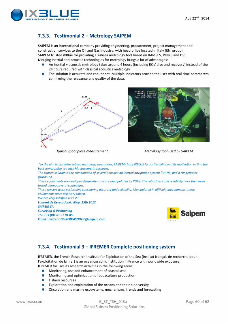
Aug 22nd , 2014
www.ixsea.com G_ST_TSH_043a Page 60 of 62Global Subsea Positioning Solutions
7.3.3. Testimonial 2 – Metrology SAIPEM
SAIPEM is an international company providing engineering, procurement, project management andconstruction services to the Oil and Gas industry, with head office located in Italy (ENI group).SAIPEM trusted iXBlue for providing a subsea metrology tool based on RAMSES, PHINS and DVL.Merging inertial and acoustic technologies for metrology brings a lot of advantages:
An inertial + acoustic metrology takes around 4 hours (including ROV dive and recovery) instead of the24 hours required with classical acoustics metrologyThe solution is accurate and redundant. Multiple indicators provide the user with real time parametersconfirming the relevance and quality of the data.
Typical spool piece measurement Metrology tool used by SAIPEM
“In the aim to optimize subsea metrology operations, SAIPEM chose IXBLUE for its flexibility and its motivation to find thebest compromise to reach his customer’s purposes.The chosen solution is the combination of several sensors: an inertial navigation system (PHINS) and a rangemeter(RAMSES).These equipments are deployed deepwater and are manipulated by ROVs. The robustness and reliability have then beentested during several campaigns.These sensors were performing considering accuracy and reliability. Manipulated in difficult environments, theseequipments were also very robust.We are very satisfied with it.”Laurent de Kervasdoué , May, 25th 2012SAIPEM SA,Surveying & PositioningTel: +33 (0)1 61 37 81 85Email : [email protected]
7.3.4. Testimonial 3 – IFREMER Complete positioning system
IFREMER, the French Research Institute for Exploitation of the Sea (Institut français de recherche pourl'exploitation de la mer) is an oceanographic institution in France with worldwide exposure.IFREMER focuses its research activities in the following areas:
Monitoring, use and enhancement of coastal seasMonitoring and optimization of aquaculture productionFishery resourcesExploration and exploitation of the oceans and their biodiversityCirculation and marine ecosystems, mechanisms, trends and forecasting
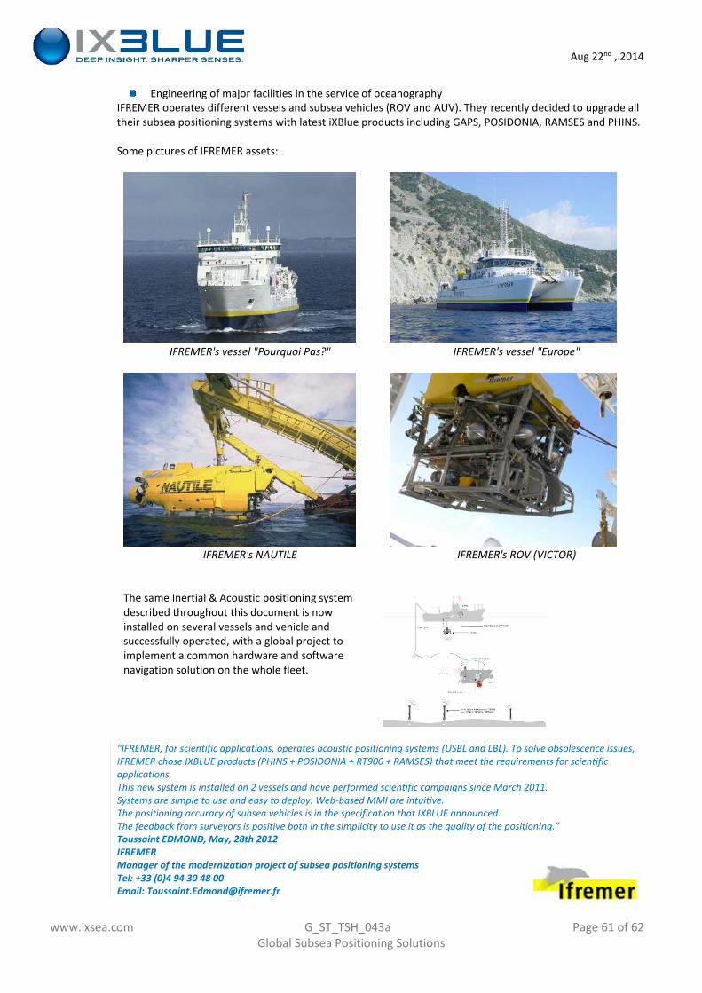
Aug 22nd , 2014
www.ixsea.com G_ST_TSH_043a Page 61 of 62Global Subsea Positioning Solutions
Engineering of major facilities in the service of oceanographyIFREMER operates different vessels and subsea vehicles (ROV and AUV). They recently decided to upgrade alltheir subsea positioning systems with latest iXBlue products including GAPS, POSIDONIA, RAMSES and PHINS.
Some pictures of IFREMER assets:
IFREMER's vessel "Pourquoi Pas?" IFREMER's vessel "Europe"
IFREMER's NAUTILE IFREMER's ROV (VICTOR)
The same Inertial & Acoustic positioning systemdescribed throughout this document is nowinstalled on several vessels and vehicle andsuccessfully operated, with a global project toimplement a common hardware and softwarenavigation solution on the whole fleet.
“IFREMER, for scientific applications, operates acoustic positioning systems (USBL and LBL). To solve obsolescence issues,IFREMER chose IXBLUE products (PHINS + POSIDONIA + RT900 + RAMSES) that meet the requirements for scientificapplications.This new system is installed on 2 vessels and have performed scientific campaigns since March 2011.Systems are simple to use and easy to deploy. Web-based MMI are intuitive.The positioning accuracy of subsea vehicles is in the specification that IXBLUE announced.The feedback from surveyors is positive both in the simplicity to use it as the quality of the positioning.”Toussaint EDMOND, May, 28th 2012IFREMERManager of the modernization project of subsea positioning systemsTel: +33 (0)4 94 30 48 00Email: [email protected]

Aug 22nd , 2014
www.ixsea.com G_ST_TSH_043a Page 62 of 62Global Subsea Positioning Solutions