is 10566 (1983): methods of test for preformed fillers for ... · is : 10566 - 1983 3.3.3 report -...
TRANSCRIPT
Disclosure to Promote the Right To Information
Whereas the Parliament of India has set out to provide a practical regime of right to information for citizens to secure access to information under the control of public authorities, in order to promote transparency and accountability in the working of every public authority, and whereas the attached publication of the Bureau of Indian Standards is of particular interest to the public, particularly disadvantaged communities and those engaged in the pursuit of education and knowledge, the attached public safety standard is made available to promote the timely dissemination of this information in an accurate manner to the public.
इंटरनेट मानक
“!ान $ एक न' भारत का +नम-ण”Satyanarayan Gangaram Pitroda
“Invent a New India Using Knowledge”
“प0रा1 को छोड न' 5 तरफ”Jawaharlal Nehru
“Step Out From the Old to the New”
“जान1 का अ+धकार, जी1 का अ+धकार”Mazdoor Kisan Shakti Sangathan
“The Right to Information, The Right to Live”
“!ान एक ऐसा खजाना > जो कभी च0राया नहB जा सकता है”Bhartṛhari—Nītiśatakam
“Knowledge is such a treasure which cannot be stolen”
“Invent a New India Using Knowledge”
है”ह”ह
IS 10566 (1983): Methods of test for preformed fillers forexpansion joints in concrete paving and structuralconstruction [CED 13: Building Construction Practicesincluding Painting, Varnishing and Allied Finishing]


1s : 10% - 1983
Indian Standard
METHODS OF TESTS FOR PREFORMED FILLERS FOR EXPANSION JOINTS IN
CONCRETE PAVING AND STRUCTURAL CONSTRUCTION
Building Construction Practices Sectional Committee, BDC 13
Chairman
SERI C. P. MALIK C-4/38, Safdarjung Development Area
New Delhi
Members Representing
SHRI P. D. AGARWAL Public Works Department, Government of Uttar Pradesh, Lucknow .
SHRI R. K. MA~HUR ( Alternate) SHRI SIJRAJ S. J. BAHADUR Housing & Urban Development Corporation
Ltd, New Delhi SHRI D. R. BATLIVALA Bhabha Atomic Research Centre, Bombay SHRI J. R. BHALLA Indian Institute of Architects New Delhi CHIEF ENGINEER ( NORTH ) Public Works Department, Government of
Punjab, Chandigarh CHIEF ENGINEER ( BLDGS ), PWD, Public Works Department, Government of Tamil
MADRAS Nadu, Madras SUPERINTENDING ENGINEER ( SPECIAL
BUILDING CIRCLE ), PWD, MADURAI ( Alternate )
CHIEF ENGINEER-CUM-ADDITIONAL Public Works Department, Government of SECRETARY TO THE GOVT ( B&R )
EXECUTIVE ENGINEER ( DESIGNS & Rajasthan, Jaipur
SPECIFICATION ) ( Alternate ) CHIEF ENGINEER ( TRAINING ) Central Public Works Department, New Delhi
SUPERINTENDINQ SURVEYOR OF WORKS ( TRAINING ) ( Alternate )
D rDtxg o R ( ARCHITECTURE ), Railway Board, Ministry of Railways
JOINT DIRECTOR ( ARCHITECTURE ), RDSO ( Alternate )
SHRI R. G. GOKHALE State Bank of India, Bombay
( Continued on page 2 )
0 Copyright 1983
INDIAN STANDARDS INSTITUTION
This publication is protected under the Indian Copyright Act ( XIV of 1957) and reproduction in whole or in part by any means except with written permission of the publisher shall be deemed to be an infringement of copyright under the said Act.
IS : 10566 - 1983
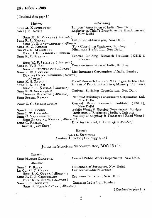
( Continued from page 1 )
Members
SHRI M. KARTIKAYAN SHRI J. s. KOHLI
Representing
Builders’ Association of India, New Delhi Engineer-in-Chief’s Branch, Army Headquarters,
New Delhi SHRI M. G. VIRMANI ( Alternate )
SHRIIR. L. KUXAR Institution of Surveyors, New Delhi Sam V. G. PATWARDHAN ( Alternate )
SHRI M. 2. KURIEN Tata Consulting Engineers, Bombay SHRI:G. K. MAJ~JMDAR Hindustan Prefab Ltd, New Delhi
SHRI H. S. PASRICHA ( Alternate ) SHRI R. C. MANUAL Central Building Research Institute ( CSIR ),
Roorkee SHRI M. P. JAISINQH ( Alternate )
SHRI B. V. B. PAI Concrete Association of India, Bombay SHRI P. SRINIVASAN ( Alternate )
SHRI R. K. PANDARE Life Insurance Corporation of India, Bombay DEPUTYCHIEF ENGINEER (NORTH)
( Alternate ) SHRI K. S. PRLTTHI SHRIT.K.SARAN
SHRI S. S. KAWAL (Alternate) SHRI K: S. SRINIVASAN
DEPUTY DIRECTOR ( Alternate ) SHRI SUSHIL KUMAR
PROF C. G. SWAMINATHAN Central Road Research Institute ( CSIR ), New Delhi
SHRI S, R. TAMBE SHRI B. T. UNWALLA SHR~G.VENKATESULU
Public Works & Housing Department, Bombay Institution of Engineers ( India ), Calcutta Ministry of Shipping & Transport ( Road Wing )
Forest Research Institute & Colleges, Dehra Dun Bureau of Public Enterprises, Ministry of Finance
National Buildings Organisation, New Delhi
National Buildings Construction Corporation Ltd, New Delhi
SHRI PRAFULLA KUMAR ( Alternate ) SHRI G. RAMAN, Director General, IS1 ( Ex-oficio Member )
Director ( Civ Engg )
Secretary
SHRI S. SENQUPTA Assistant Director ( Civ Engg ), IS1
Joints in Structure Subcommittee, BDC 13 : 14
Convener
SHRI HARISH CHANDRA Central Public Works Department, New Delhi
Members
SHRI J. P. BAJAJ Institution of Surveyors, New Delhi LT-COL C. T. CHARI Engineer-in-Chief’s Branch
SHRI S. K. GUPTA ( Alternate ) SHRI R. C. P. CHOUDHARY Engineers India Ltd, New Delhi
SHRI K. N. SINHA ( Alternate ) SHRI P. S. GOKHALE Gammon India Ltd, Bombay
SERI K. RAJAGOPALAN (Alternate) ( Continued on page 11 )
2

IS:10566 - NW
Indian Standard
METHODS OF TESTS FOR PREFORMED FILLERS FOR EXPANSION JOINTS IN
CONCRETE PAVING AND STRUCTURAL CONSTRUCTION
0. FOREWORD
0.1 This Indian Standard was adopted by the Indian Standards Institution on 28 February 1983, after the draft finalized by the Building Construction Practices Sectional Committee had been approved by the Civil. Enginee- ring Division Council.
0.2 Hitherto, methods of tests to assess the qualitative requirements of bitumen impregnated preformed fillers for expansion ,joints were included in IS : 1838-1961*. To unify the test methods to be used for other types of preformed fillers made from cork, rubber, PVC, epoxy, etc, it has been decided to modify and cover these methods in a separate Indian Standard. Though some of the methods may not be considered suitable for testing preformed fillers made from PVC, rubber, etc, it has been decided by the Committee to modify these methods in future to suit all types of fillers as and when it becomes necessary.
0.2.1 In this standard, the procedure for determining the dimensions accurately has been added, procedure for calculating water absorption has been modified to assess it in terms of volume, and procedure for determi- ning the density included. Further, modification to the method for calculating the percentage of recovery is being actively considered by the committee and will be added as and when final recommendations are made available.
0.3 In the formulation of this standard due weightage has been given to the standards and practices prevailing in different countries.
0.4 In reporting the results of a test or analysis made in accordance with this standard, if the final value observed or calculated is to be rounded off it shall be done in accordance with IS : 2-196Ot.
*Specification for preformed fillers for expansion joints in concrete non-extruding and resilient type ( bitumen impregnated fibre ).
$Rules for rounding off numerical values ( revised ).
3
lS:10566 -1983
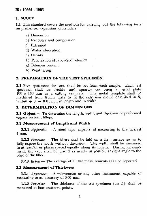
1. SCOPE
1.1 This standard covers the methods for carrying out the following tests on preformed expansion joints fillers:
a) Dimension
b) Recovery and compression
c) Extrusion
d) Water absorption
e) Density
f ) Penetration of recovered bitumen
g) Bitumen content
h) Weathering
2. PREPARATION OF THE TEST SPECIMEN
2.1 Five specimens for test shall be cut from each sample. Each test specimen shall be freshly and squarely cut using a metal plate 100 X 100 mm as a cutting template. The metal template shall be machined from 6 mm plate to fit the extrusion mould described in 5, within + 0, - 0.01 mm in length and in width.
3. DETERMINATION OF DIMENSIONS
3.1 Object - To determine the length, width and thickness of preformed expansion joint fillers.
3.2 Measurement of Length and Width
3.2.1 Apparatus - A steel tape capable of measuring to the nearest 1 mm.
3.2.2 Procedure - The fillers shall be laid on a flat surface so as to fully expose the width without distortion. The width shall be measured in at least.three places spaced equally along its length. During measure- ment, the ,tape shall be placed as nearly as possible at right angle to the edge of the filler.
3.2.3 Report - The average of all the measurements shall be reported.
3.3 Measurement of Thickness
3.3.1 Apparatus - A micrometer or any other instrument capable of measuring to an accuracy of 0.01 mm.
3.3.2 Procedure - The thickness of the test specimen ( see 2 ) shall be measured at four scattered points.
4

IS : 10566 - 1983
3.3.3 Report - The average of all the observations shall be reported.
4. DETERMINATION OF RECOVERY AND COMPRESSION
4.1 Object - To determine the following properties of preformed fillers:
a) Percentage of recovery, b) Resistance to compression, and c) Loss in bitumen.
4.2 Apparatus - A typical mounting for the test is shown in Fig. 1. Place the test specimen on a Aat metal plate and centre a 110 x 110 x 12 mm metal plate ground to have plane parallel faces on the top surface of the specimen. Use a simple U shape bridge to support a dial gauge or other suitable measuring device reading to 0.02 mm above the centre of specimen. Place a hollow metal load transfer cylinder with slots for inserting the U shape bridge and an opening for reading the measuring device between the moving head of the testing machine and the plate covering the specimen. Mount a spherical bearing block between the upper end of the cylinder and the moving head of the testing machine. Centre accurately both the hollow metal cylinder or other device and the spherical bearing block in order that the load shall be applied uniformly to the test specimen.
4.3 Procedure - When the specimen has been mounted as in 4.2 and is subjected to only the pressure of the dead weight of 110 x 110 x 12 mm metal plate, determine its thickness by means of the measuring device. When the load transferring apparatus and spherical bearing block are placed on the test specimen some compression may result. Consider this reduction in thickness as part of the 50 percent reduction in thickness to be applied.
4.3.1 Recouery - For the determination of the percentage of recovery, the test specimen shall be compressed to 50 percent of its thickness before the test by single application of load. The load shall be immediately released after application. The thickness of the specimen shall be mea- sured at the end of ten minutes after release of the load. Should the specimen show a recovery of less than 70 percent of its thickness before the test, the test shall be repeated as specified in 4.2.
4.3.2 Subject the test specimen three applications of load sufficient to compress it to 50 percent of its thickness before the test. Apply the load without shock and at such a rate that the specimen shall be compressed approximately 1.0 mm per minute. After the first and second applications release the load immediately, and permit the specimen to recover for 30 minutes before the load is again applied. After the third application release the load immediately and permit the specimen to recover for one
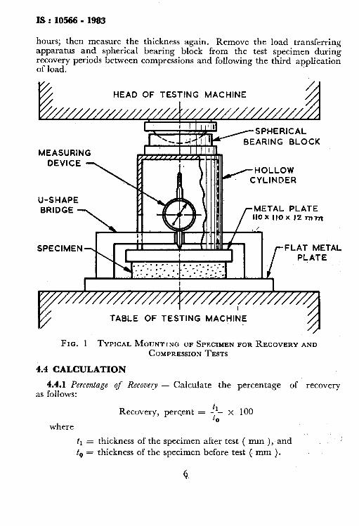
IS : 10566 - 1983
hours; then measure the thickness again. Remove the load transferring apparatus and spherical bearing block from the test specimen during recovery periods between compressions and following the third application of load.
ARING BLOCK
MEASURING
U-SHAPE METAL PLATE 110 x 110 x I2 rnml
FLAT METAL
TABLE OF TESTING MACHINE
FIG. 1 TYPICAL MOUNTING OF SPFEIMEN FOR RECOVERY AND COMPRESSION TESTS
4.4 CALCULATION
4.4.1 Percentage of Recovery - Calculate the percentage of recovery as follows:
where
Recovery, percent = :i-- x 100
tl = thickness of the specimen after test ( mm ), and t,-, = thickness of the specimen before test ( mm ),

IS : 10566 - 1983
4.4.2 Resistance to Compression - Calculate the I esistance to compression as follows:
Compression, kgf/mma ( or N/mms ) =-T
where
W = total maximum load required for the first application ( see 4.3.1 ), kgf( or N ); and
A = area of the plate, nuns.
5. DETERMINATION OF EXTRUSION
5.1 Object - To determine the amount of extrusion of the free edge of the preformed fillers.
5.2 Apparatus - Place the test specimen in a suitable steel mould so constructed as to confine the lateral movement of the specimen under compression to one side only. Interior dimensions of the mould shall be 100 x 100 mm with permissible variations of length and width of + 0.5 mm. Mould sides shall be of such a height as to extend at least 10 mm above the test specimen. Cover the specimen with a l-2 mm metal plate ground to have plane parallel faces and machined to fit snugly, but without binding, within the three restraining sides of the steel mould. Use a simple U-shaped bridge to support above the centre of the specimen a dial or other suitable measuring device reading to 0.02 mm. Place upon the plate a metal cylinder or other device for transferring the load from the moving head of the testing machine around the measuring apparatus to the plate covering the specimen. Mount a spherical bearing block between the upper end of the cylinder and the moving head of the testing machine.
5.3 Procedure - When the specimen has been mounted as described in 5.2 and is subjected only to the pressure of the dead weight of the 100 x 100 x 1.2 mm metal plate, determine its thickness by means of the measuring device. When the l.oad-transferring apparatus and spherical bearing block are placed on the test specimen, some compression may result. Consider this reduction in thickness as part of the 50 percent reduction in thickness to be applied.
5.4 For the determination of the amount of extrusion, give the specimen one application of a load sufficient to compress it to 50 percent of its thickness before the test. Apply the load without shock and at such a rate that the specimen shall be compressed approximately 1 *O mm per minute. Determine the amount of extrusion in millimetres by measuring the maximum movement of the free edge of the test specimen during the 50 percent compression of the specimen. Measure the extrusion by means of a dial or other suitable device reading to 0.02 mm.
IS : 10566 - 1983
6. DETERMINATION OF WATER ABSORPTION
6.1 Object - To determine the percentage water absorption of prefor- med fillers.
6.2 Test Specimen - Cut a specimen 100 x 100 mm from the joint material in such a way that all edge are freshly cut.
6.3 Procedure - Dry the specimen at ambient temperature, when not less than 20°C; for 24 hours in a desiccator and in case of lower tempera- ture dry in oven at 20 f 2°C and weigh to the nearest 0.1 g. Immerse in water maintained at a temperature of 20 f 2°C in a horizontal position with 25 mm of water over the specimen for 24 hours. Remove the specimen from the water and remove the surface water from all side of the specimen with a blotting paper. Quickly weigh the specimen and calculate the percentage of absorption as follows:
Water absorption, percent by volume E lO(Wr--ws> --
t
where
M;i = weight of the test piece after immersion, g;
W, = weight of the test piece before immersion, g; and
t = thickness of specimen before test, in,mm.
7. DETERMINATION OF DENSITY
7.1 Object - To assess the amount of density of preformed expansion joint fillers.
7.2 Specimen - Cut a test specimen 100 X 100 mm.
7.3 Procedure - Dry the specimen at ambient temperature, when not less than 2O”C, for 24 hours in a desiccator and in case of lower ambient temperature dry in oven at 20 f 2°C and weigh to the nearest 0.1 g. Determine the dimensions of the specimen to the nearest 0.1 mm and calculate the density as follows:
density, kg/m3 = weight of the specimen volume of the specimen
8. DETERMINATION OF PENETRATION OF RECOVERED BITUMEN
8.1 Object - To determine the amount of penetration of the recovered bitumen at 25°C of bitumen impregnated preformed expansion joint fillers.
8
IS : 10586 - 1983
8.2 Apparatus and Reagents
8.2.1 Centrijiigal Extractor - Rotarex type.
8.2.2 Head Resistant class Flask
8.2.3 Condenm - Water cooled.
8.2.4 Benzene
8.3 Procedure
8.3.1 Weigh a 150 to 200 g sample of the joint filler to the nearest ._ 0.1 g, break up the sample and place it in a centrifuga1 extractor. Add
pure benzene in sufficient quantity to saturate the sample, then allow the sample to soak for 30 minutes to dissolve the bitumen. Extract the bitumen-benzene solution by centrifuging the sample. Add several successive washes of pure benzene to the centrifuge bowl until the extrac- ted solvent is not discoloured and all the bitumen sat&ant has been removed from the fibre joint filler.
8.3.2 Collect the bitumen-benzene solution and the washings in a 2 litres round-bottom, heat resistant glass flask and distill over on oil-bath, with a water cooled condenser for condensing the benzene vapours. Continue the distillation until the bitumen-benzene solution is concentra- ted to approximately 200 ml. Stop the distillation at this point, pour the residue into a 3004 distillation flask and distill at 360°C.
8.3.3 Determine the penetration of the recovered bitumen according to IS : 1203-1978*.
9. DETERMINATION OF BITUMEN:CONTENT
9.1 Object - To determine the percentage of bitumen content in the bitumen impregnated preformed expansion joint fillers.
9.2 Procedure - Dry the fibre residue to constant weight, after the extraetion of the bitumen in accordance with 8.3.1. Determine the bitumen content by difference, expressed as a percentage by weight of the original sample.
10. DETERMINATION OF WEATHERING
10.1 Object - To examine the effect of accelerated weathering on the preformed expansion joint fillers.
*Methods for testing tar and bituminous materials - Determination of penetration (jut revision ) .

IS:10!%6-1983
10.2 Procedure - Expose the test specimen as described in 2, to a temperature of 75 f 1°C for a period of 7 days. Upon completion of this accelerated ageing immerse the specimen in water at room temperature for 24 hours.
10.2.1 Place the specimen on edge in a suitable container and pour water into the container to a depth of 50 mm ( one-half height of the specimen ) . It shall be necessary to put a weight or simple frame .across the exposed edges of the specimen during this test in order to maintain the position of the specimen in the water. Place the container containing the specimen in a freezing chamber for a period long enough to freeze the water into solid ice. Maintain the temperature of the freezing chamber between - 4 to - 6°C. Upon completion of the freezing cycle remove the pan containing the specimen from the freezing chamber and partially immerse in water at a temperature maintained between 18 and 38°C.: The first cycle is completed when the ice surrounding the specimen h% melted entirely, Repeat this cycle ten times. ‘. -”
10.3 Result
10.3.1 After completion of ten freezing and thawing cycles remove the specimen from the water and allow it to stand in room temperature for 48 hours. Examine the test specimen for evidences of disintegration.

IS:lO!M-1983
( Continuedfrom page 2 )
Members Representing
SHRI G. B. JAHAUIRDAR National Industrial Development Corporation Ltd, New Delhi
SHRI M. P. JAISINQH CentrRaArte.lding Research Institute ( CSIR ),
SHRI R. K. JAIN ( Alternate ) SERI S. R. KULKARNI M. N. Dastur & Company ( P ) Ltd, Calcutta
SHRI D. B. GHOSH ( Alternate ) DR M. NAYAK Concrete Association of India, Bombay
SHRI P. SRINIVASAN ( Alternate ) SHRI Y. R. PHuLL Central Road Research Institute, New Delhi
SHRI K. L. SETHI ( Alternate ) SHRI P. V. RAMAEXURTHY Directorate General Border Roads, New Delhi
SHRI R. P. SETH ( Alternate ) SHRI SAMOEL F. Indian Institute of Architects, New Delhi SHRI S. SEETHARAIKAN Min$r; ;ffeSFipping & Transport ( Roads Wing ),
e SRRI PRAFULLA Ku~~AR. ( Alternate )
SHRI K. S. SRINIVASAN National Buildings Organization, New Delhi SHRI A. K. LAL ( Alternate)
SERI SUSHIL KUMAR National Building Construction Corporation Ltd, . . . New Delhi
SHRI DALJIT SINGH (Alternate ) SUPERINTENDINQ SURVEYOR OF Central Public Works Department, New Delhi
WORKS SURVEYOR OF WORKS ( C ) ( Alternate)
11

_.“. ._^ _. . . __ -. - .._ -II-“..,~
Bare Units
Quantity
Length
Mass
Time’ Electric current
Thermodynamic temperature
Luminous intensity
Amount of substance
Supplementary Units
Quantity
Plane angle
Solid angle
Derived Units
Qeant!ty
Force
Energy
Power Flux
Flux density
Frequency
Electric conductance Electromotive force Pressure, stress
INTERNATIONAL SYSTEM OF UNITS ( SI UNITS) P
Unit
metre
kilogram
second
ampere
.kelvin
Symbol
m
kg
:
K
candela
mole
cd
mol
Unit
radian
steradlan
Symbol
rad
sr
Unit,
newton
joule,
watt weber
tesla hertz siemens
volt
Pascal
Symbol
N
J
w
Wb T
HZ
‘S V
Pa
N w 1 kg.m/ss
J I 1 N.m
W * I J/s Wb = 1 V.s
T = 1 Wb)m’
Yr = 1 c/s (S-J) S - 1 A/V
v * 1 W/A
Pa I 1 N/m: