interfacing paging systems - autronica...
TRANSCRIPT

Release 3
Interfacing Paging Systems
ESPA Interface Module BSL-333
Protecting life, environment and property...
P-ESPA/EE 020910 Rev. A

COPYRIGHT ©
This publication, or parts thereof, may not be reproduced in any form, by any method, for any purpose. Autronica Fire and Security AS and its subsidaries assume no reponsibility for any errors that may appear in the publication, or for damages arising from the information in it. No information in this publication should be regarded as a warranty made by Autronica Fire and Security. The information in this publication may be updated without notice. Product names mentioned in this publication may be trademarks. They are used only for identification.

Table of Contents
Interfacing Paging Systems, AutroSafe Interactive Fire Alarm System, Release 3, P-ESPA/EE 020910 Rev. A, Autronica Fire and Security AS
Page 1
Table of Contents
1. Introduction......................................................................4 1.1 About the Handbook.......................................................................... 4 1.2 The Reader........................................................................................ 4 1.3 Terms ................................................................................................ 4
2. About the ESPA Interface Module ..................................5 2.1 Description......................................................................................... 5 2.2 AutroSafe Software Requirements.................................................... 5 2.3 ESPA Service Pack ........................................................................... 6 2.4 Overview............................................................................................ 6 2.5 Typical Application............................................................................. 7 2.6 SMS Messages ................................................................................. 7 2.7 Specifications BSL-333 Module......................................................... 8 2.8 Dimensions........................................................................................ 8 2.9 Indicators and Buttons....................................................................... 9 2.10 Dip-switches – Overview ................................................................... 9
3. Installation and Cable Connections Overview ..............10 3.1 Installing the Programs on the Computer.......................................... 10 3.2 Installing the Serial Port Communication Board EAU-321 ................ 11
3.2.1 Jumper Settings ...................................................................... 11 3.2.2 Connections on Terminal Blocks X1 and X2 (if used)............. 12 3.2.3 Mounting the Board ................................................................. 12
3.3 Installing the BSL-333 Module........................................................... 13 3.3.1 General.................................................................................... 13 3.3.2 Mounting onto the Standard Mounting Rail Inside the
Cabinet .................................................................................... 13 3.3.3 Mounting on an External DIN-rail ............................................ 13
3.4 Cable Connections Overview ............................................................ 14 3.4.1 Connection between EAU-321 and Port 1 on the BSL-333
module .................................................................................... 14 3.4.2 Connection between the computer (configuration) and
Port 1 on the BSL-333 module................................................ 15 3.4.3 Connection between the computer (test) and
Port 2 on the BSL-333 module................................................ 16
4. Quick Reference Guide ...................................................17
5. What you need to know about the paging system ........18 5.1 Basic Information............................................................................... 18 5.2 Special Issues ................................................................................... 19

Table of Contents
Interfacing Paging Systems, AutroSafe Interactive Fire Alarm System, Release 3, P-ESPA/EE 020910 Rev. A, Autronica Fire and Security AS
Page 2
6. About the BSL-333-Configuration ..................................20 6.1 Introduction........................................................................................ 20 6.2 “AutroCom formatted” Configuration ................................................. 20 6.3 Configuration principles ..................................................................... 21 6.4 Short Description of the BSL-333 Configuration Tables.................... 22 6.5 Example of BSL-333 Configuration ................................................... 23 6.6 Planning the BSL-333 Configuration ................................................. 24
6.6.1 Display Size............................................................................. 24 6.6.2 Fire System Events to Page.................................................... 24 6.6.3 Receivers to be Paged............................................................ 25 6.6.4 Priority Queue ......................................................................... 25 6.6.5 Multiple Receivers for one Event............................................. 25 6.6.6 Receiver Priorities ................................................................... 26
6.7 Technical alarms ............................................................................... 26 6.7.1 Introduction.............................................................................. 26 6.7.2 AutroSafe Config..................................................................... 27 6.7.3 Common Configuration of the BSL-333 Module ..................... 27 6.7.4 Selective Configuration ........................................................... 28
7. Configuring the AutroSafe System.................................30 7.1 Introduction........................................................................................ 30 7.2 Configuring the AutroSafe System .................................................... 30 7.3 Connecting the Cable ........................................................................ 33 7.4 Downloading the AutroSafe Configuration ........................................ 33
8. Preparing the BSL-333-module.......................................34 8.1 Introduction........................................................................................ 34 8.2 Setting Dip-switches .......................................................................... 34 8.3 Connecting the Cable ........................................................................ 35 8.4 Setting Baudrates .............................................................................. 36
8.4.1 Entering Executive Mode (EXE).............................................. 36 8.4.2 Setting Parameters / KD485 Configuration Program .............. 37 8.4.3 Leaving Executive Mode (EXE)............................................... 37
9. Configuring the Customized Setup of the BSL-333-module ...............................................................38
9.1 Introduction........................................................................................ 38 9.2 Configuring the BSL-333 module ...................................................... 39 9.3 Loading BSL-333 Configuration using AutroCom Test Program ...... 40 9.4 Setting up Communication ................................................................ 41 9.5 The AutroSafe Emulator.................................................................... 42
9.5.1 Editing the BSL-333 Configuration .......................................... 43 9.5.2 Sending the BSL-333 Configuration........................................ 43 9.5.3 Testing the BSL-333 Configuration ......................................... 44
10. Verifying the Customised Setup of the BSL-333-module ..............................................................45
10.1 Introduction........................................................................................ 45 10.2 Verification Procedure ....................................................................... 45

Table of Contents
Interfacing Paging Systems, AutroSafe Interactive Fire Alarm System, Release 3, P-ESPA/EE 020910 Rev. A, Autronica Fire and Security AS
Page 3
11. Verifying the paging functionality with a complete system setup...................................................47
11.1 Introduction........................................................................................ 47 11.2 Verification Procedure ....................................................................... 48
12. Interfacing Off-site GSM Telephones (SMS Messages)...............................................................49
12.1 Introduction........................................................................................ 49 12.2 Cable Connections ............................................................................ 49 12.3 Configuration for AutroTel Module BSL-334 ..................................... 50
13. Troubleshooting ..............................................................51 13.1 Self Monitoring................................................................................... 51 13.2 Quick system overview...................................................................... 53
13.2.1 AutroSafe communication....................................................... 53 13.2.2 Pager communication ............................................................. 53 13.2.3 “Check wiring” ......................................................................... 54 13.2.4 “BSL-333 program not executing properly” ............................. 54
13.3 AutroCom problems on the AutroSafe side....................................... 55 13.4 Testing ESPA output from BSL-333.................................................. 61 13.5 Testing ESPA input to Paging System .............................................. 63
14. BSL-333- Configuration Tables.......................................66 14.1 The Settings table.............................................................................. 66 14.2 The Events table................................................................................ 68 14.3 The Receivers table........................................................................... 69 14.4 Func/state for the Events table.......................................................... 70
14.4.1 Search order for the Events table ........................................... 70 14.5 Display Texts ..................................................................................... 71
14.5.1 Dynamic <..> fields in Display Texts. ...................................... 71 14.5.2 Considerations for Display Texts ............................................ 72
15. Appendix ..........................................................................73 15.1 Verifying the Communication between AutroSafe and the
BSL-333 Module using the default BSL-333 Configuration .............. 73 15.1.1 Introduction.............................................................................. 73 15.1.2 Preparations – AutroSafe Configuration ................................. 73 15.1.3 Verification Procedure............................................................. 74 15.1.4 Default BSL-333 Configuration ............................................... 76
15.2 Screw Terminals on the BSL-333 Module......................................... 77 15.3 Character sets for AutroSafe............................................................. 77 15.4 ESPA 7-Bit character set (ISO 646) .................................................. 78 15.5 GSM SMS character set (GSM 03.38) .............................................. 79
16. Reader’s Comments ........................................................81

Introduction
Interfacing Paging Systems, AutroSafe Interactive Fire Alarm System, Release 3, P-ESPA/EE 020910 Rev. A, Autronica Fire and Security AS
Page 4
1. Introduction
1.1 About the Handbook This handbook provides the information necessary to successfully interface the AutroSafe Interactive Fire Alarm system to on-site wireless pagers, using the ESPA Interface Module BSL-333 and one port on the Serial Port Communication Board EAU-321. The interface to off-site GSM telephones requires the additional AutroTel Module BSL-334. Information on this equipment is included in a separate chapter (Interfacing Off-site GSM Telephones – SMS Messages).
1.2 The Reader The handbook is intended to be used by trained service and technical personnel with great knowledge of: • AutroSafe functionality • AutroSafe Configuration Data (output from the
AutroSafeConfiguration Tool, configuration files)
1.3 Terms • The ESPA Interface Module BSL-333 is referred to as the BSL-333
module throughout the handbook. • Pager is synonymous with the terms pocket receiver, receiver and
pocket pager. • AutroCom is AutroSafe’s interface to 3rd party equipment. • AutroSafeConfig is the configuration data which is downloaded to
the AutroSafe system by means of the AutroSafe Configuration Tool.

About the ESPA Interface Module
Interfacing Paging Systems, AutroSafe Interactive Fire Alarm System, Release 3, P-ESPA/EE 020910 Rev. A, Autronica Fire and Security AS
Page 5
ESPA Interface Module BSL-333
2. About the ESPA Interface Module
2.1 Description The ESPA Interface Module BSL-333 is an RS-232 interface module used to interface on-site wireless pagers or off-site GSM telephones using BSL-334 ESPA to SMS Interface. The ESPA Interface Module supports a large number of paging systems with ESPA 4.4.4 protocol. The following AutroCom events can be paged: • fire alarms • prealarms • faults • technical alarms from I/O units Texts from AutroSafe may include the name of a Detection Zone and Tag Names (point information), plus general fault texts. The type of message to be transmitted to each pager is configurable, as well as the number of pagers the messages are transmitted to. Typically, a system will be configured to transmit all types of messages to some pagers, and only fire alarm messages to other pagers. The same type of pagers must be used within a system. A large number of pagers or group numbers can be used.
(The BSL-333 module has a configurable memory of 2000 bytes (characters). This is not divided into fixed tables, but rather reflects the user’s configuration. This means that there is no fixed limit on how many pocket receivers that can be configured.) The module is connected to the AutroSafe via the AutroCom protocol.
2.2 AutroSafe Software Requirements The use of ESPA Interface Module requires AutroSafe software version 3.2.0 or newer.

About the ESPA Interface Module
Interfacing Paging Systems, AutroSafe Interactive Fire Alarm System, Release 3, P-ESPA/EE 020910 Rev. A, Autronica Fire and Security AS
Page 6
2.3 ESPA Service Pack The ESPA Service Pack (AS-ESPASERVPACK) includes the necessary programs, cables and documentation. The CD-ROM, including; • The KD485 Configuration Program for baud rate settings • AutroCom Test Program for loading the BSL-333 Configuration • The Pager Tester (testing ESPA out of BSL-333 and ESPA into
paging system) • Documentation in pdf-format: the handbook AutroSafe - Interfacing
Paging Systems and the data sheet for the BSL-333 module. Cables • Communication Cable XJA-036 is used between the computer and
Port 1 on the BSL-333 module. • Communication Cable XJA-037 is used between the computer and
Port 2 on the BSL-333 module.
2.4 Overview
AutroSafe – BS-320 / BC-320 panels
Power
Fire Brig. Signalled
Function Delayed
Function Disabled
0
ALARM
i
C
987
654
321
Mute Panel
Silence Alarms
Reset
More Events
Testing
Fire Brig. Disabled
System Fault
Alarms Disabled
Fire Brig. Fault
Fault
Alarms Fault
AUTROSAFESelfVerify
19:23
EAU-321
Paging System
Serial PortCommunication Board
ESPAInterface ModuleBSL-333
Pager
AutroTel ModuleBSL-334

About the ESPA Interface Module
Interfacing Paging Systems, AutroSafe Interactive Fire Alarm System, Release 3, P-ESPA/EE 020910 Rev. A, Autronica Fire and Security AS
Page 7
2.5 Typical Application The drawing below shows a typical application of the BSL-333 module.
2.6 SMS Messages As an alternative to pager, a GSM telephone can be used. To be able to send SMS messages to GSM telephones additional equipment is required: AutroTel Module BSL-334. This unit provides ESPA interface (input) and can transmit SMS via a built-in GSM telephone. Refer to Interfacing Off-site GSM Telephones – SMS Messages, chapter 12.
AutroSafe – BS-320 / BC-320 panels
Power
Fire Brig. Signalled
Function Delayed
Function Disabled
0
ALARM
i
C
987
654321
Mute Panel
Silence Alarms
Reset
More Events
Testing
Fire Brig. Disabled
System Fault
Alarms Disabled
Fire Brig. Fault
Fault
Alarms Fault
AUTROSAFESe lfVerify
19:23
EAU-321AutroTel Module
BSL-334
Serial PortCommunication Board
ESPAInterface ModuleBSL-333
GSM Telephone
123456
TX
ESPAInterface Module
BSL-333
RX
RXA
TXA
654321
+-
PowerInput
P1 GND
Cable shield
Power Supply7-35V DC
+-
TX (5)RX (3)
GND (9)
PORT 1 PORT 2
P2 GNDAutroSafeProtocolConverter
78
PagingSystemTX
RX
Cable shield is optional for RS232
Serial Port CommunicationBoard EAU-321
GND123456
TX
ESPAInterface Module
BSL-333
RX
RXA
TXA
654321
+-
PowerInput
P1 GND
Cable shield
Power Supply7-35V DC
+-
TX (5)RX (3)
GND (9)
PORT 1 PORT 2
P2 GNDAutroSafeProtocolConverter
78
PagingSystemTX
RX
Cable shield is optional for RS232
Serial Port CommunicationBoard EAU-321
GND

About the ESPA Interface Module
Interfacing Paging Systems, AutroSafe Interactive Fire Alarm System, Release 3, P-ESPA/EE 020910 Rev. A, Autronica Fire and Security AS
Page 8
2.7 Specifications BSL-333 Module Mounting Mounted on rail. DIN-rail enclosure with
removable screw terminals; fits 35mm symmetric rails
Ports Two asynchronous ports, TX & RX signals only.
Interface Options port 1 is RS232; port 2 is RS232.
RS-232 Receiver threshold + 1.5V typ. Receiver Rin 5kΩ typ. TX o/p ±8V typ (3k load).
Power supply + 7V to + 35V DC. + 12V DC Input power approx. constant at 1-2 watts (startup current 300-600mA) depending on model. At startup, the supply voltage must reach 7V in <1 sec.
Isolation 64V PK, tested at >1000V AC RMS, 1 second.
Environmental Operating temperature 0 to +50C. Storage temperature -25C to + 70C. Relative humidity (operating and storage) 0 to 90%, non-condensing.
EMC compliance Emissions EN50081-2 (94), immunity EN50082-2 (95).
Dimensions 29mm (W) x 113mm (H) x 100mm (L) approximately in rail-mounted position, including screw terminals.
2.8 Dimensions The drawing below shows the dimensions of the BSL-333 module.

About the ESPA Interface Module
Interfacing Paging Systems, AutroSafe Interactive Fire Alarm System, Release 3, P-ESPA/EE 020910 Rev. A, Autronica Fire and Security AS
Page 9
2.9 Indicators and Buttons The BSL-333 module has the following indicators and buttons: • 2TX: Red LED - Send (TX) Port 2 (to pager).
Blinking light (0,5 second intervals) indicates that signals are being sent.
• 2RX: Red LED - Receive (RX) Port 2 (to pager). Blinking light (0,5 seconds intervals) indicates that signals are being received.
• 1TX: Red LED - Send (TX) Port 1 (to EAU-321 – AutroSafe). Blinking light (3 seconds intervals) indicates that signals are being sent.
• 1RX: Red LED - Receive (RX) Port 1 (to EAU-321 – AutroSafe). Blinking light (3 seconds intervals) indicates that signals are being received.
• EXE: Red LED – Executive Mode (when setting parameters) o Blinking light (1 second intervals) when green button has been
pressed. o Normal operation: EXE Lights steady while a message is sent
to the paging system • PWR: Yellow LED – Steady light indicates Power ON. • Green Executive Mode button. Used to enter Executive Mode
(when setting parameters). • Grey rotary switch (default factory settings - 0).
2.10 Dip-switches – Overview For ESPA installations, all dip-switches are to be set in OFF position.
4O
N3
21
(front side)
(rear side)
Top View of BSL-333 Module
Dip-switch block
2TX
2RX
1TX
1RX
EXE
PWR
ESPAModule
BSL-333

Installation and Cable Connections Overview
Interfacing Paging Systems, AutroSafe Interactive Fire Alarm System, Release 3, P-ESPA/EE 020910 Rev. A, Autronica Fire and Security AS
Page 10
3. Installation and Cable Connections Overview
3.1 Installing the Programs on the Computer The ESPA Protocol Interface CD (AS-ESPACD) includes • The KD485 Configuration Program • AutroCom Test Program • The Pager Tester Make sure that these programs are installed on your service computer. • Insert the CD-ROM and install the programs one by one. Note: The use of one computer with one serial port is described in this handbook. Note that it is possible to use several computers at the same time (if several serial ports / computers are available).

Installation and Cable Connections Overview
Interfacing Paging Systems, AutroSafe Interactive Fire Alarm System, Release 3, P-ESPA/EE 020910 Rev. A, Autronica Fire and Security AS
Page 11
3.2 Installing the Serial Port Communication Board EAU-321
3.2.1 Jumper Settings
The table below gives an overview of the jumper settings for the Serial Port Communication Board EAU-321. Jumpers J5 and J6: J5 and J6 must be set to interrupt 2 and 5.
Jumpers J8 (interrupt) J8 must be set to interrupt 7 and R.
Jumpers J9, J10 and J11 (interrupt) All ports must be set to interrupt 7. Jumper J7 (board address) Jumper in position A and B must be set to In. This setting applies to all communication boards. Gives board address 100h.
CBA
I/O header Port 3 and 4
J5
J6
J7
Serial Port Communication Board EAU-321
J8J9
J10J11
Port 1
Port 2I/O header Port 1 and 2
Addressjumpers
Port 4
Port 3
I/O header Port 3 and 4
J5
J6
J7
Serial Port Communication Board EAU-321
J8J9
J10J11
Port 1
Port 2I/O header Port 1 and 2
Addressjumpers
Port 4
Port 3
J5
J6
J7
Serial Port Communication Board EAU-321
J8J9
J10J11
Port 1
Port 2I/O header Port 1 and 2
Addressjumpers
Port 4
Port 3
15 12 11 10 7 6 5 4 3 2 R15 12 11 10 7 6 5 4 3 2 R
15 12 11 10 7 6 5 4 3 2 R15 12 11 10 7 6 5 4 3 2 R
TXRXCTDCDSR1123456
TXRXCTDCDSR1123456

Installation and Cable Connections Overview
Interfacing Paging Systems, AutroSafe Interactive Fire Alarm System, Release 3, P-ESPA/EE 020910 Rev. A, Autronica Fire and Security AS
Page 12
3.2.2 Connections on Terminal Blocks X1 and X2 (if used)
2018161412108642
191715131197531
NC
DSR 2RTS 2CTS 2RI 2
RXD 2TXD 2DTR 2GND
DCD 2
DSR 1RTS 1CTS 1RI 1NC
DCD 1RXD 1TXD 1DTR 1GND
Port 2
Port 1
X1
3.2.3 Mounting the Board
The Serial Port Communication Board, EAU-321 is to be mounted onto the LON Interface Board EAU-310* (if the system is a distributed system) or directly onto the Processor Board EAC-300 (if the system is a standalone system).
The board can be mounted inside any BS-310/320 panel or BC-320 Controller. However in a distributed system the board should preferably be mounted inside the Booting Panel.
* The illustration below shows how to mount the EAU-321 board onto the LON Interface Board, EAU-310 inside a system unit (Fire Alarm Control Panel or Controller).
LON Interface Board, EAU-310
Serial Port Communication Board, EAU-321 (Reference: Dwg. no. UD-706)
Terminal Block X2 Terminal Block X1
Processor Board, EAC-300

Installation and Cable Connections Overview
Interfacing Paging Systems, AutroSafe Interactive Fire Alarm System, Release 3, P-ESPA/EE 020910 Rev. A, Autronica Fire and Security AS
Page 13
3.3 Installing the BSL-333 Module
3.3.1 General
The paging system should be placed in the same room. Normally, RS232 distance limitations apply – i.e. maximum 15 metres. If longer distances are required shielded cable is recommended. (Port 2 is isolated, i.e. there are no problems with grounding).
3.3.2 Mounting onto the Standard Mounting Rail Inside the Cabinet
The module is connected to the AutroSafe via one RS232 port on the Serial Port Communication Board, EAU-321 (EAU-321 supports up to 2 AutroCom links). The BSL-333 module can be mounted and plugged onto the standard mounting rail inside the Fire Alarm Control Panel / Controller. The module is powered from AutroSafe’s 24V DC power. If the module is to be mounted onto the standard mounting rail inside the cabinet, the dip-switch on the module must be pointing to the left when the module is to be inserted. • Snap the left side of the
fastener onto the mounting rail (1), then press the module slightly inwards (2) until the right side fastens.
3.3.3 Mounting on an External DIN-rail
Alternatively, the module can also be placed on an external DIN-rail and powered with an external 24V DC.

Installation and Cable Connections Overview
Interfacing Paging Systems, AutroSafe Interactive Fire Alarm System, Release 3, P-ESPA/EE 020910 Rev. A, Autronica Fire and Security AS
Page 14
3.4 Cable Connections Overview
3.4.1 Connection between EAU-321 and Port 1 on the BSL-333 module
Port 1 on the BSL-333 module is used for the cable connection from AutroSafe, while Port 2 is used for the connection to the paging system. There are two alternative ways of connecting the RS232 Serial Interface Cables. Alternative A: Connection to EAU-321 directly If there is no free space inside the AutroSafe cabinet for the screw connector, connect directly to the flat cable connector on EAU-321 with cable XBA-055. The used pins are in the top row.
Communication Cable XBA-055 is used between the Serial Communication Board EAU-321 and Port 1 on the BSL-333 module.

Installation and Cable Connections Overview
Interfacing Paging Systems, AutroSafe Interactive Fire Alarm System, Release 3, P-ESPA/EE 020910 Rev. A, Autronica Fire and Security AS
Page 15
Alternative B: Connection by means of the screw connector (X1 and X2) This alternative may be suitable in larger systems where several ports are to be used. Note that the screw connector is not standard. • Connect the cable from the Serial Port Interface Board
EAU-321 (inside the AutroSafe BS-320) to the connector (Port 1) on the BSL-333 module.
• Connect the cable from the connector (Port 2) on the BSL-333 module to the paging system (the connector for connection to the paging system may vary depending on the type of paging system).
3.4.2 Connection between the computer (configuration) and Port 1 on the BSL-333 module
Communication Cable XJA-036 (test purposes) is used between the computer and Port 1 on the BSL-333 module when AutroCom Test Program is to be used.
Connector BSL-333 to Port 1

Installation and Cable Connections Overview
Interfacing Paging Systems, AutroSafe Interactive Fire Alarm System, Release 3, P-ESPA/EE 020910 Rev. A, Autronica Fire and Security AS
Page 16
3.4.3 Connection between the computer (test) and Port 2 on the BSL-333 module
Communication Cable XJA-037 (test purposes) is used between the computer and Port 2 on the BSL-333 module when PagerTest Program is to be used.
Connector computer to BSL-333, Port 2
Quick Reference Guide
Interfacing Paging Systems, AutroSafe Interactive Fire Alarm System, Release 3, P-ESPA/EE 020910 Rev. A, Autronica Fire and Security AS
Page 17
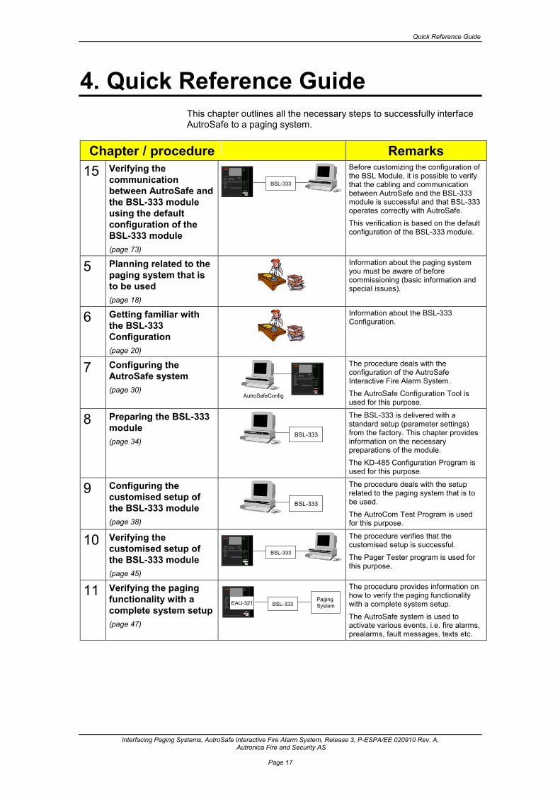
4. Quick Reference Guide This chapter outlines all the necessary steps to successfully interface AutroSafe to a paging system.
Chapter / procedure Remarks
15 Verifying the communication between AutroSafe and the BSL-333 module using the default configuration of the BSL-333 module (page 73)
BSL-333Power
Fire Brig. recvd.
Fire vent. activ.
Fire ext.. acktivat ed
0
A L A R MA L A R MA L A R MA L A R M
?
C
987
654321
Silence buz zer
Sile nce sounde rs
Re set
More Ala rms
Pre warning
Early wa rning
System fa ult
Function disa bled
Test
Fault
S elf Verify
Before customizing the configuration of the BSL Module, it is possible to verify that the cabling and communication between AutroSafe and the BSL-333 module is successful and that BSL-333 operates correctly with AutroSafe. This verification is based on the default configuration of the BSL-333 module.
5 Planning related to the paging system that is to be used (page 18)
Information about the paging system you must be aware of before commissioning (basic information and special issues).
6 Getting familiar with the BSL-333 Configuration (page 20)
Information about the BSL-333 Configuration.
7 Configuring the AutroSafe system (page 30)
AutroSafeConfig
Power
Fire Brig. re cvd.
Fire ve nt. activ.
Fire e xt.. a cktivated
0
A L A R MA L A RMA L A RMA L A RM
?
C
987
654
321
Silence buzzer
Silence sounders
Rese t
More Alarms
Prewarning
Early warning
Sys tem faultFunction disa bled
Tes t
Fault
Self Verify
The procedure deals with the configuration of the AutroSafe Interactive Fire Alarm System. The AutroSafe Configuration Tool is used for this purpose.
8 Preparing the BSL-333 module (page 34)
BSL-333
The BSL-333 is delivered with a standard setup (parameter settings) from the factory. This chapter provides information on the necessary preparations of the module. The KD-485 Configuration Program is used for this purpose.
9 Configuring the customised setup of the BSL-333 module (page 38)
BSL-333
The procedure deals with the setup related to the paging system that is to be used. The AutroCom Test Program is used for this purpose.
10 Verifying the customised setup of the BSL-333 module (page 45)
BSL-333Power
Fire Brig. recvd.
Fire vent. activ.
Fire ext.. acktivated
0
A LA R MA LA RMA LA RMA LA RM
?
C
987
654321
Silence buz zer
Sile nce sounde rs
Re set
More Ala rms
Pre warning
Early wa rning
System fa ultFunction disa bledTest
Fault
S elf Verify
The procedure verifies that the customised setup is successful. The Pager Tester program is used for this purpose.
11 Verifying the paging functionality with a complete system setup (page 47)
Power
Fire Brig. recvd.
Fire vent. activ.
Fire ext.. acktivat ed
0
A L A R MA L A R MA L A R MA L A R M
?
C
987
654321
Silence buz zer
Sile nce sounde rs
Re set
More Ala rms
Pre warningEarly wa rning
System fa ultFunction disa bledTest
Fault
S elf Verify
BSL-333Paging SystemEAU-321
The procedure provides information on how to verify the paging functionality with a complete system setup. The AutroSafe system is used to activate various events, i.e. fire alarms, prealarms, fault messages, texts etc.

What you need to know about the paging system
Interfacing Paging Systems, AutroSafe Interactive Fire Alarm System, Release 3, P-ESPA/EE 020910 Rev. A, Autronica Fire and Security AS
Page 18
5. What you need to know about the paging system
5.1 Basic Information To avoid possible problems caused by wrong settings or preparations on the paging system, it is important to know the following basic information about the paging system that is to be used, including: RS232 Hardware What type of port is used: D-Sub, 9 or 25 pins, screw terminals, RJ-45? Get the pin-out! (You may have to make test cables from your PC to this plug). Does the serial interface have LEDs or similar that can be used to monitor operation? RS232 line settings Autronica recommends 9600 baud, 8 bits, No parity, 1 stop bit. (The original ESPA protocol defined 1200 baud, 7 bits, Even parity, 2 stop bits. This is not well suited for today’s long display texts, or the use of international character sets). The receiver’s display • Total number of characters in one message • The line length of the display (used for “word wrap”). BSL-333 can make display texts that are close to 100 characters long. Displays shorter than 32 characters will require special considerations when setting up all DZ/point texts in AutroSafe Config to make the information useful on a small display. Use of receiver group numbers Most paging systems have the possibility to page groups. This means that BSL-333 only have to send a single paging call to reach a number of receivers, which gives fast system response. If possible, plan to use group numbers for receivers with identical pagings. Number plan for the receivers Some paging systems uses “hidden” prefixes to the receiver numbers. BSL-333 can use receiver numbers of any length, and the numbers are entered as text so it is possible to use letters as part of the numbers.

What you need to know about the paging system
Interfacing Paging Systems, AutroSafe Interactive Fire Alarm System, Release 3, P-ESPA/EE 020910 Rev. A, Autronica Fire and Security AS
Page 19
ESPA Beep codes suitable for Alarm, Pre-alarm and Faults. A Beep Code is a numeric code between 1 and 9. Character set for national characters • BSL-333 uses an 8-bit Windows character set internally, which can
represent all (Western) European characters. • If the Paging system uses an older 7-bit national character set, it is
necessary to get a conversion table. (see typical national character sets in Appendix here).
• Some older receivers have displays that support only UPPER case letters.
5.2 Special Issues Identical pagings Some paging systems accept more than one paging call at a time. They are then often set up to ignore identical pagings. If possible, have the paging system set up so that it will send ALL pagings even if they are identical. (This may not be a problem during normal operation, but if you are testing with a single Manual CallPoint, you risk that you “loose” repeated alarms inside the paging system.) Queuing of status messages Paging systems that store multiple calls can store the status of a call for a period (say one minute) after it has been paged. During this period the paged call “blocks” internal table space, so that the interface may reject new pagings. BSL-333 will not read such status, and internal tables should be freed up as quickly as possible.

About the BSL-333-Configuration
Interfacing Paging Systems, AutroSafe Interactive Fire Alarm System, Release 3, P-ESPA/EE 020910 Rev. A, Autronica Fire and Security AS
Page 20
6. About the BSL-333-Configuration
6.1 Introduction The main configuration allows each installation to tune the behaviour regarding: • What events to page • How the event is presented in the receiver • Which receivers will be paged for each type of event The configuration is written in a symbolic, software version independent, format. The configuration is handled by the AutroCom Test Program. Configuration data is sent to the BSL-333 module as one AutroCom message per Config text line.
6.2 “AutroCom formatted” Configuration Each line of Config represents one line (or part of a line) of a table. The general layout is: <TableId[Index]>;<Value1>;<Value2>;… // Comment Each <ValueN> is encoded as <FieldName=Value> Example: Receiver table. Receivers[1]; Address=123; Events=1,2; //Technical staff Receivers[2]; Address=345; Events=2,3,4; //Mr. Smith
The Config messages will be parsed by BSL-333 when they arrive. If they contain unknown text, BSL-333 will send a Fault message to the AutroSafe panel display.
About the BSL-333-Configuration
Interfacing Paging Systems, AutroSafe Interactive Fire Alarm System, Release 3, P-ESPA/EE 020910 Rev. A, Autronica Fire and Security AS
Page 21
6.3 Configuration principles The Config is based on three assumptions: • Messages from the Fire system are sent to just a few persons.
They have identical pocket receivers. • There is a lot of ESPA equipment out there, all slightly different.
Some systems configure pager brands and model numbers, and the ESPA behavior is then hard-coded based on brand knowledge. The BSL-333 can be configured for the various ESPA properties directly.
• The texts presented on displays must be in a local language. The texts will be different for each installation, depending on the size of the displays used. The BSL-333 allows texts to be modified during commissioning, thus giving each customer what he wants! The system is delivered with “model texts” in English.

About the BSL-333-Configuration
Interfacing Paging Systems, AutroSafe Interactive Fire Alarm System, Release 3, P-ESPA/EE 020910 Rev. A, Autronica Fire and Security AS
Page 22
6.4 Short Description of the BSL-333 Configuration Tables
The BSL-333 Configuration consists of a number of tables (a plain text file), including: • The Settings Table • The Events Table • The Receivers Table Each table consists of a number of lines. Each table line can be configured using one of more text lines. A short overview of the fields in each table is included below. For detailed information on each field in the BSL-333 Configuration Tables, refer to separate chapter (chapter 14).
Table Fields The Settings Table Settings[1]; Char8=ÆØÅæøå;
Settings[1]; Char7=[/]|;
Settings[1]; Alphabet=7; Upper=0;
Settings[1]; DisplaySize=120; LineLength=12;
The table has only one line.
The Events Table Events[1]; Func=05; State=A;
Events[1]; Priority=1; Beeps=3; Transm=3;
Events[1]; Text=*Fire Alarm* <DZ>;
Each Event consists of two parts: • The identification of the event,
which is implemented very close to the AutroCom protocol’s messages
• The expression of the event, which is how the pocket receiver will behave when paged with this event. These values are close to the ESPA protocol.
The Receivers Table // Owner: N.N.
Receivers[1]; Address=100; Events=0; OZ=0;
There is one line in the Receivers table for each pocket receiver that shall be notified about events in the Fire System.

About the BSL-333-Configuration
Interfacing Paging Systems, AutroSafe Interactive Fire Alarm System, Release 3, P-ESPA/EE 020910 Rev. A, Autronica Fire and Security AS
Page 23
6.5 Example of BSL-333 Configuration Config is a plain text file.
// Config for BSL-333 ESPA Interface //------------------------------------ // // // General settings //---------------------------------------------- Settings[1]; Char8=ÆØÅæøå; Settings[1]; Char7=[/]|; Settings[1]; Alphabet=7; Upper=0; Settings[1]; DisplaySize=120; LineLength=12; // Events causing wireless paging: //-------------------------------- // - Detector statuses Events[1]; Func=05; State=A; Events[1]; Priority=1; Beeps=3; Transm=3; Events[1]; Text=*Fire Alarm* <DZ>; Events[2]; Func=05; State=P; Events[2]; Priority=2; Beeps=2; Transm=1; Events[2]; Text=FirePreAlarm <DZ>; Events[3]; Func=05; State=Y; Events[3]; Priority=2; Beeps=2; Transm=1; Events[3]; Text=FireEWarning <DZ>; // - Fault messages Events[4]; Func=03; Events[4]; Priority=3; Beeps=1; Transm=1; Events[4]; Text=FireSysFault Unit= <UI> Message= <CL>. <RE>; // - Internal faults in the BSL-333 Events[5]; Func=00; Number=1; Events[5]; Priority=3; Beeps=1; Transm=1; Events[5]; Text=Pager Status AutroSafe communication <ST=FAULT,OK>; // - Technical alarms from inputs: Events[6]; Func=34; Number=0; Events[6]; Priority=2; Beeps=2; Transm=1; Events[6]; Text=Techn. Alarm <UI> |Status=<ST=OFF,ON>; // // List of pocket receivers, with event filter //---------------------------------------------- // Owner: N.N. Receivers[1]; Address=100; Events=0; OZ=0; // Owner: N.N. Receivers[2]; Address=002; Events=1,4; OZ=1;
The index “[1]” of each table line is actually a tag that need not be sequentially increasing line by line. The “[1]” tag of the Events table is referenced by each line in the Receivers table, “Events=1,4;” This means that you can e.g. delete Events[3] (early warning) without having to re-configure the Receivers table. Also, if an Event is not referenced by any Receiver, it will not cause paging, but it can be left in the table for possible future use. (When the BSL-333 Configuration is loaded, every new, unknown tag will cause allocation of “next free” memory address. Skipping tag values does not “reserve” memory unnecessarily).

About the BSL-333-Configuration
Interfacing Paging Systems, AutroSafe Interactive Fire Alarm System, Release 3, P-ESPA/EE 020910 Rev. A, Autronica Fire and Security AS
Page 24
6.6 Planning the BSL-333 Configuration
6.6.1 Display Size
Decide what display size is to be used. • A regular fire alarm message consists of a prefix text like “Fire
Alarm” followed by a DZ text of max. 34 characters (plus an optional point tag of max. 24 characters).
• A Fault message consist of a prefix text, the name of the faulty unit (34 chars), followed by a Class and a Reason text each max. 40 characters, for a total of some 120 characters. The display formatting will suppress trailing spaces, so the text will usually be more like 50-70 characters.
Today’s high-end receivers can typically receive messages up to 120 characters, in which case the display layout is non-critical. If smaller displays are to be used, for example 16 or 32 characters, it’s possible to use shorter prefix texts, and the text information from AutroSafe can also be configured to have a fixed length. In this way a Fault message can present useful pieces of all texts involved. Another important property of the pager displays is the character set (alphabet) it can present. ESPA specified originally “English only” characters, while most brands have implemented ways to show (European) national characters. Check the details for the transmitter/receivers you select.
6.6.2 Fire System Events to Page
The following events can be configured to start paging: • Detector status
Fire Alarm, Pre-Alarm, (Early Warning) Fire events are paged as quickly as possible. It is not possible to “wait for” DZ level alarms with coincidence or delays.
• Faults Point faults, system faults
• Internal faults of the BSL-333 • Technical alarms
(FPE response inputs) Along with the event you configure how it shall be paged (display text, priority etc.).

About the BSL-333-Configuration
Interfacing Paging Systems, AutroSafe Interactive Fire Alarm System, Release 3, P-ESPA/EE 020910 Rev. A, Autronica Fire and Security AS
Page 25
6.6.3 Receivers to be Paged
The system has a list of pocket receivers. Each receiver is related to one or more of the events that can start paging. This means that for each event occurring, zero, one or more receivers are informed. There is even an advanced option where receivers can be grouped by OZ (Operation Zone), that is, be informed only by events on points in limited geographical areas (buildings).
6.6.4 Priority Queue
The Pager Queue holds events that are ready to be paged, sorted on arrival time and event (ESPA) priority. The queue length is 30 in the current version. If the queue becomes full, the most recent, lowest priority entry will be thrown away (lost). The recommended Config uses the following priorities: First Alarms and PreAlarms, then Faults. In a fire situation, typically one or more PreAlarms will be followed by real Fire Alarms. Faults are of little interest during a real Fire, as Faults occur as a side effect of the fire. If a system is configured with different priorities on Alarm and PreAlarm, or lower priority EarlyWarning is used, there is a chance that the Page Queue can hold e.g. a PreAlarm and an Alarm from the same point at the same time. The Alarm will then be paged first, and it’s confusing to later page the (older) PreAlarm on the same point, so it will be deleted.
6.6.5 Multiple Receivers for one Event
BSL-333 can be configured so that multiple receivers are notified about the same event. But sending say 10 SMS messages takes considerable time, maybe a minute or more. The system must respond quickly in situations where a low priority event is followed by a high priority event a few seconds later. This is solved by storing the “active” receiver in each Page Queue entry. Every time a message has been sent to a single receiver, the Page Queue is re-evaluated to find the most important entry. If the current entry has been replaced by a high priority entry, the new entry will be paged to all it’s receivers, then removed from the queue. The previous entry, still in queue, will then finish paging it’s remaining receivers.

About the BSL-333-Configuration
Interfacing Paging Systems, AutroSafe Interactive Fire Alarm System, Release 3, P-ESPA/EE 020910 Rev. A, Autronica Fire and Security AS
Page 26
6.6.6 Receiver Priorities
The Receivers table is always searched in the sequence given by the Config; always starting with the first entry (the [index] value is not used here; if [1] is last it will be paged last). This means that the first receiver should be the person that needs the fire system’s information fastest (in the normal case we talk about just seconds in difference here, but again, a SMS system could have noticeable delays).
6.7 Technical alarms
6.7.1 Introduction
“Technical Alarm” means that when a digital input changes state, some text is sent to one or more pagers. AutroSafe has no inputs called “Technical Alarms”. But it’s possible to use Fire Protection Equipment units in the BN320/x product range, as they have an input monitoring capability. As long as a FPE is not “Activated” by AutroSafe, the input can change without any nasty side effects (Activated units have timeouts on the monitoring inputs causing AutroSafe FAULTs!). The Technical Alarm paging can be used to: • Report status of units controlled by AutroSafe, e.g. fans starting or
fire doors closing. Any BN-320/x can be monitored. • Report status of units used only as inputs.
BN-320/4 “Standard Control Unit” will be the best choice here. Note also that BN-320/4 has a second input, which can be used to generate FAULTS related to the connected equipment.
As the BN-320/x units are loop units, they are not allowed to generate many events in a short time. It’s not possible to use them as a “door bell”!

About the BSL-333-Configuration
Interfacing Paging Systems, AutroSafe Interactive Fire Alarm System, Release 3, P-ESPA/EE 020910 Rev. A, Autronica Fire and Security AS
Page 27
6.7.2 AutroSafe Config
Regular FPEs are ADD’ed to a loop, then assigned an “Activation Group” in AutroSafe Config. This is described in standard AutroSafe documentation. “Input only” FPEs that are to be used as pure “Technical Alarms” must also be ADD’ed to a loop, but shall have no “Activation Group”. You will get a warning when generating the Config, which you can ignore (this capability is by design). Note that the BN320/x units have “input filtering”. A change of the input’s state is reported after a configurable time. If the input returns to its previous state within this time, nothing is reported. This time is called “Normal Monitoring Timer” in BN-320/4 (it’s the first of 3 timer settings for all of them). In addition to the configurable time, the unit’s software adds 2 seconds “minimum filter” time.
6.7.3 Common Configuration of the BSL-333 Module
To monitor all FPEs you add the following to the BSL-333 Config file:
// - Technical Alarms (FPE inputs) Events[6]; Func=34; Number=0; Events[6]; Priority=2; Beeps=3; Transm=1; Events[6]; Text=Techn. Alarm <UI> <ST=OFF,ON>;
(You must use a free tag-no for “Events[<tag-no>]”). If you want alarm messages only when the inputs go ON, change the display text to “..<ST=,ON>..” (that is, take away the word “OFF”, but leave the comma “;”).

About the BSL-333-Configuration
Interfacing Paging Systems, AutroSafe Interactive Fire Alarm System, Release 3, P-ESPA/EE 020910 Rev. A, Autronica Fire and Security AS
Page 28
6.7.4 Selective Configuration
Depending on the installations number of FPEs, and how many of them shall cause paging, you may have to do more selective configuration of the BSL-333. Selective configuration can also be used to give more meaningful status texts, like “door <ST=OPEN,CLOSED>”, “motor <ST=STOPPED,STARTED>” etc. To obtain a “selective configuration” you must add each FPE input to the Config as a separate Event. Due to a limitation in the Receivers table’s “Events=…”, you must select Event <tag-no> in one of two ways: • If all technical alarms shall go to the same receivers, use <tag-no>
above 31. The Receivers then all be configured as “Events=…,31” Only the Config memory size limits the number of FPEs added this way.
• If selected technical alarms shall go to selected receivers, use <tag-no> below 31. Each Receiver can then have settings like “Events=…,10”, “Events=…,11”, and so on. Max 25 FPEs can be handled like this (30 minus normal alarm events).
The FPEs are distinguished by the “Number” parameter of the Events[] entry. AutroSafe Config assigns this number automatically when you ADD a FPE. To find it, select the FPE unit in AutroSafe Config, and look at the top of the right pane. In the example below, Number is “1”.
This particular FPE is then referenced in BSL-333 Config like this:
Events[32]; Func=34; Number=1;
Example: All specified technical alarms go to Receiver[2] // . . . // Main Door status Events[32]; Func=34; Number=1; Events[32]; Priority=2; Beeps=3; Transm=1; Events[32]; Text=Door Alarm <UI> <ST=OPEN,CLOSED>; // // Fan status Events[33]; Func=34; Number=2; Events[33]; Priority=2; Beeps=3; Transm=1; Events[33]; Text=Fan Alarm <UI> <ST=STOPPED,STARTED>; // // List of pocket receivers, with event filter //---------------------------------------------- Receivers[1]; Address=999; Events=0; OZ=0; Receivers[2]; Address=001; Events=1,2,3,31; OZ=0;

About the BSL-333-Configuration
Interfacing Paging Systems, AutroSafe Interactive Fire Alarm System, Release 3, P-ESPA/EE 020910 Rev. A, Autronica Fire and Security AS
Page 29
Example: Selected alarms to selected pagers. Event[10] goes to Receiver[2], and so on. // . . . // Main Door status Events[10]; Func=34; Number=1; Events[10]; Priority=2; Beeps=3; Transm=1; Events[10]; Text=Door Alarm <UI> <ST=OPEN,CLOSED>; // // Fan status Events[11]; Func=34; Number=2; Events[11]; Priority=2; Beeps=3; Transm=1; Events[11]; Text=Fan Alarm <UI> <ST=STOPPED,STARTED>; // // List of pocket receivers, with event filter //---------------------------------------------- Receivers[1]; Address=999; Events=0; OZ=0; Receivers[2]; Address=001; Events=1,2,3,10; OZ=0; Receivers[3]; Address=002; Events=1,2,3,11; OZ=0;
Example: Some alarms with custom texts, the remaining ones shall use a standard text ON/OFF. // . . . // Main Door status Events[10]; Func=34; Number=1; Events[10]; Priority=2; Beeps=3; Transm=1; Events[10]; Text=Door Alarm <UI> <ST=OPEN,CLOSED>; // // Fan status Events[11]; Func=34; Number=2; Events[11]; Priority=2; Beeps=3; Transm=1; Events[11]; Text=Fan Alarm <UI> <ST=STOPPED,STARTED>; // // All remaining inputs Events[12]; Func=34; Number=0; Events[12]; Priority=2; Beeps=3; Transm=1; Events[12]; Text=Techn. Alarm <UI> <ST=OFF,ON>; // // List of pocket receivers, with event filter //---------------------------------------------- Receivers[1]; Address=999; Events=0; OZ=0; Receivers[2]; Address=001; Events=1,2,3,10,12; OZ=0; Receivers[3]; Address=002; Events=1,2,3,11,12; OZ=0;
6.7.4.1 Advanced Display Texts for Technical Alarms
A Technical Alarm will be most important when it goes “active”. You have the option to inform the receivers even when it goes inactive, but you may want to use a more polite language. You can use several <ST=….> fields within one text. Try for example: Events[12]; Text=Fan <ST=Info,Alarm> <UI> <ST=Stopped,STARTED>;
It will generate the texts (differences underlined): • Fan Alarm Main Building Fan STARTED • Fan Info Main Building Fan Stopped

Configuring the AutroSafe System
Interfacing Paging Systems, AutroSafe Interactive Fire Alarm System, Release 3, P-ESPA/EE 020910 Rev. A, Autronica Fire and Security AS
Page 30
7. Configuring the AutroSafe System
7.1 Introduction
AutroSafeConfig
Power
Fire Brig. recvd.
Fire vent. activ.
Fire ext.. acktivated
0
A L A RMA L A RMA L A RMA L A RM
?
C
987
654
321
Silence buzzer
Silence sounders
Reset
More Alarms
Prewarning
Early warning
System fault
Function disabledTest
Fault
Self Verify
Cable XJA-033
The procedure deals with the configuration of the AutroSafe Interactive Fire Alarm System. The AutroSafe Configuration Tool is used for this purpose. The chapter includes the following: • Configuring the AutroSafe System • Connecting the cable for downloading • Downloading the AutroSafe Configuration
7.2 Configuring the AutroSafe System The necessary configuration of the AutroSafe includes the following: • From the Main Menu in AutroSafe Configuration Tool, click on View
and select System (System View). • In the Tree View on the left side of the screen, click on the Panel
(BS-320) where the AutroCom Serial is to be added. Note: Make sure that the selected panel is actually the one where the Serial Port Communication Board EAU-321 is mounted.
• Right-click the mouse and select Add.

Configuring the AutroSafe System
Interfacing Paging Systems, AutroSafe Interactive Fire Alarm System, Release 3, P-ESPA/EE 020910 Rev. A, Autronica Fire and Security AS
Page 31
• In the popup menu that appears, write the name of unit to be added, and state the number of units to be added (if necessary).
• Click on AutroCom Serial in the Entity window, then click on the Add button.
• In the Tree View, click on the AutroCom Serial (in this example named AUTROCOM_SERIAL_Pager).

Configuring the AutroSafe System
Interfacing Paging Systems, AutroSafe Interactive Fire Alarm System, Release 3, P-ESPA/EE 020910 Rev. A, Autronica Fire and Security AS
Page 32
• Select port number, 1 or 2. • Verify the parameter settings (baud rate to 9 600 baud, 8 bits, none
parity, 1 stopbit).
• Set the AutroCom Type to SERIAL_SLIDING_WINDOW in the drop-down box to the right.
• From the Main Menu, click on View and select Operation View. • In the Tree View on the left side of the screen, click on the top level
OZ (Operation Zone) – that is, if there are several Operation Zones in the AutroSafe system.
• Right-click the mouse and select Connect.
• In the popup menu that appears, select the Pager (in this example
we have given the Unit this name), then click on the Connect button.
• In the Tree View, verify that the AutroCom Serial (in this example,
Pager) is connected to the correct OZ (Operation Zone).

Configuring the AutroSafe System
Interfacing Paging Systems, AutroSafe Interactive Fire Alarm System, Release 3, P-ESPA/EE 020910 Rev. A, Autronica Fire and Security AS
Page 33
7.3 Connecting the Cable A cable (XJA-033 Communication Cable EAU-321 / Computer) is used for the connection between the computer and the EAU-321 board inside the Fire Alarm Control Panel (the Booting Panel in a distributed system).
• Connect the ribbon cable to the EAU-321 Board (Port 4 is
dedicated for downloading of configuration files), connection J4 (P4) (the upper left ribbon cable connector), with the red wire pointing down.
• Connect the other end of the cable to one of the serial ports on the computer.
7.4 Downloading the AutroSafe Configuration The AutroSafe Configuration can be downloaded to all system units in a distributed system from a single Fire Alarm Control Panel (the one which is defined as the Booting Panel (System ID=01). To download the configuration, you have to use the ConfigDownload Tool. For detailed information on the Configuration and Commissioning Procedure for AutroSafe, refer to the Commissioning Handbook. NOTE: When the downloading is completed and the system is running (normal operation), a fault warning will occur as the paging system at this stage is still not connected (i.e. no paging system connected to AutroCom Serial).

Preparing the BSL-333-module
Interfacing Paging Systems, AutroSafe Interactive Fire Alarm System, Release 3, P-ESPA/EE 020910 Rev. A, Autronica Fire and Security AS
Page 34
8. Preparing the BSL-333-module
8.1 Introduction
BSL-333Cable XJA-036
The BSL-333 is delivered with a standard setup (parameter settings) from the factory. This chapter provides information on this standard setup. The KD-485 Configuration Program is used for this purpose (chapter 3.1). The preparation of the BSL-333 module includes the following: • Setting dip-switches • Connecting the cable • Entering Executive Mode • Setting parameters
8.2 Setting Dip-switches The illustration below shows the dip-switch settings on the BSL-333 module. All dip-switches must be set in position OFF. The rotary switch on the front panel must be set to 0.
4O
N3
21
(front side)
(rear side)
Top View of BSL-333 Module

Preparing the BSL-333-module
Interfacing Paging Systems, AutroSafe Interactive Fire Alarm System, Release 3, P-ESPA/EE 020910 Rev. A, Autronica Fire and Security AS
Page 35
8.3 Connecting the Cable Before entering Executive Mode (EXE) and setting the required parameters, the necessary cabling must be done. • Consult the cable drawing below.
• Connect the cable from the 24V DC power source to the connector
7 and 8 (Port 1) on the BSL-333 module. • Connect the test cable from the computer's serial port to the
connector (Port 1) on the BSL-333 module. Communication Cable XJA-036 is used between the computer and Port 1 on the BSL-333 module.
NOTE: If port 1 on the BSL-333 is connected to AutroSafe, the cable has to be disconnected before doing the necessary parameter settings via the computer.
BSL-333
Test cable XJA-036 Power Cable

Preparing the BSL-333-module
Interfacing Paging Systems, AutroSafe Interactive Fire Alarm System, Release 3, P-ESPA/EE 020910 Rev. A, Autronica Fire and Security AS
Page 36
8.4 Setting Baudrates If the standard baudrates are correct, go directly to Configuring the Customised Setup of the BSL-333 module, chapter 9.
8.4.1 Entering Executive Mode (EXE)
The BSL-333 module must be electronically configured before it can be used. Configuration must be done via Port 1, which has to be set to Executive Mode. • To enter Executive Mode, press and hold down the green
Executive Mode button on the front panel approximately 5 seconds until the EXE indicator starts blinking, then release it.
A few seconds later (approximately 3-4 seconds), the red EXE indicator will blink rapidly (1second ON / 1 second OFF), and you can start the configuration program KD485.
EXE Indicator
Green Executive ModeButton
2TX
2RX
1TX
1RX
EXE
PWR
ESPAModule
BSL-3332TX
2RX
1TX
1RX
EXE
PWR
ESPAModule
BSL-333

Preparing the BSL-333-module
Interfacing Paging Systems, AutroSafe Interactive Fire Alarm System, Release 3, P-ESPA/EE 020910 Rev. A, Autronica Fire and Security AS
Page 37
8.4.2 Setting Parameters / KD485 Configuration Program
The parameter settings for Port 1 (AutroSafe) and Port 2 (Paging system) are done by means of the KD485 Configuration Program, which is delivered with the BSL-333 module. • Make sure that the BSL-333 module is in Executive Mode. The
EXE indicator should be blinking rapidly. If not, communication is not established, and you must repeat the procedure described in the previous section (Entering Executive Mode).
• Start KDCFG.EXE, and the Configuration Menu will appear on
screen. • Verify that Mode is set to OFF (on the right uppermost side).
• Set the baud rate for Port 1 (AutroSafe) to 9 600 baud, 8 bits, none
parity, 1 stopbit, (which is the default setup of AutroSafe). Note that these parameters can be changed for AutroSafe by means of the AutroSafe Configuration Tool.
• Choose RX Xon/Xoff disabled • Choose TX Xon/Xoff disabled
Set the appropriate parameters for Port 2 (Paging system) according to the requirements. Recommended: 9 600 baud, 8 bits, none parity, 1 stopbit.
• Click on the highlighted button marked Update KD485 and the message Writing new KD485 Configuration will appear on screen.
When the message disappears, and the Update KD485 button no longer is highlighted, all parameters have been set and the configuration is completed. NOTE: If you later want to check the port settings, simply start the KDCFG.EXE again. It will read out the actual settings from the BS-333 module before displaying the configuration window.
8.4.3 Leaving Executive Mode (EXE)
To leave Executive Mode, press the green Executive Mode button on the front panel or turn the power OFF/ON.
Not to be
used

Configuring the Customized Setup of the BSL-333-module
Interfacing Paging Systems, AutroSafe Interactive Fire Alarm System, Release 3, P-ESPA/EE 020910 Rev. A, Autronica Fire and Security AS
Page 38
9. Configuring the Customized Setup of the BSL-333-module
9.1 Introduction
BSL-333Cable XJA-036
The procedure deals with the setup (parameter settings) related to the paging system that is to be used. The AutroCom Test Program is used for this purpose (chapter 3.1). This chapter includes the following: • Connecting the cable (refer to previous chapter 8.3.) • Configuring the BSL-333 module • Loading the BLS-333 Configuration using the AutroCom Test
Program • Setting up the communication • Using the AutroSafe Emulator (in the tools menu / AutroCom Test
Program) to: o Edit the BSL-333 Configuration file (if necessary) o Send the BSL-333 Configuration o Test the BSL-333 Configuration
Computer with AutroCom Test Program

Configuring the Customized Setup of the BSL-333-module
Interfacing Paging Systems, AutroSafe Interactive Fire Alarm System, Release 3, P-ESPA/EE 020910 Rev. A, Autronica Fire and Security AS
Page 39
9.2 Configuring the BSL-333 module • The configuration of the BSL-333 module is described in detail in
chapter 6. • The necessary tables are included in chapter 14.1, 14.2 and 14.3. The configuration deals with the following tables:
Table Fields The Settings Table Settings[1]; Char8=ÆØÅæøå;
Settings[1]; Char7=[/]|;
Settings[1]; Alphabet=7; Upper=0;
Settings[1]; DisplaySize=120; LineLength=12;
The table has only one line.
The Events Table Events[1]; Func=05; State=A;
Events[1]; Priority=1; Beeps=3; Transm=3;
Events[1]; Text=*Fire Alarm* <DZ>;
Each Event consists of two parts: • The identification of the event,
which is implemented very close to the AutroCom protocol’s messages
• The expression of the event, which is how the pocket receiver will behave when paged with this event. These values are close to the ESPA protocol.
The Receivers Table // Owner: N.N.
Receivers[1]; Address=100; Events=0; OZ=0;
There is one line in the Receivers table for each pocket receiver that shall be notified about events in the Fire System.

Configuring the Customized Setup of the BSL-333-module
Interfacing Paging Systems, AutroSafe Interactive Fire Alarm System, Release 3, P-ESPA/EE 020910 Rev. A, Autronica Fire and Security AS
Page 40
9.3 Loading BSL-333 Configuration using AutroCom Test Program
AutroComTest is a communication test program that has some additional functionality that is used here. It is used to send Config into BSL-333, and it can generate data messages for FireAlarm, Fault etc. so that the paging functionality can be tested. • Connect the PC to BSL-333s port 1 (or the RJ-45 Config port) • Make sure that BSL-333 is in operation mode (NOT executive
mode) • Start AutroComTest.exe
The program’s main window is a protocol trace window. It will show that BSL-333 sends “Log_on_request” every 10 seconds. The very first time this program is run, you may have to set up communication parameters, see below.
AutroSafe Panel
AutroCom via
EAU-321
BSL-333ESPA
Interface Module
Wireless Paging System
with ESPA interface
External Link
AutroComLink
PC with
AutroCom Test

Configuring the Customized Setup of the BSL-333-module
Interfacing Paging Systems, AutroSafe Interactive Fire Alarm System, Release 3, P-ESPA/EE 020910 Rev. A, Autronica Fire and Security AS
Page 41
9.4 Setting up Communication Select the “Settings” menu entry, then sub-entry “Com Port and Protocol…” • The “Protocol” is “Serial Sliding Window”. • The default AutroCom port settings are shown; adjust them if
necessary.
Finish by pressing the “OK” button. The main window will show the “Log-on-request” messages within 10 seconds.

Configuring the Customized Setup of the BSL-333-module
Interfacing Paging Systems, AutroSafe Interactive Fire Alarm System, Release 3, P-ESPA/EE 020910 Rev. A, Autronica Fire and Security AS
Page 42
9.5 The AutroSafe Emulator • Select the menu entry “Tools”, then sub-entry “AutroSafe
Emulator”. A new window appears. Wait some 20 seconds while “RESET” and “INIT” phases are simulated, and the text “Entering OPERATION” appears. You will see the “LOGON” attempts from BSL-333 during this period. (The screenshot shows a situation where the Paging System is not connected).

Configuring the Customized Setup of the BSL-333-module
Interfacing Paging Systems, AutroSafe Interactive Fire Alarm System, Release 3, P-ESPA/EE 020910 Rev. A, Autronica Fire and Security AS
Page 43
9.5.1 Editing the BSL-333 Configuration
If necessary, the BSL-333 Config text file can be edited using any editor, for example Notepad. To test and modify it quickly, you can also edit it directly in the AutroSafe Emulator. • Read your Config by selecting the “File” menu, sub-entry “Open…”
(alternatively, click the button). A standard Windows File dialog appears, where you can navigate directories and select a file. If you have used the program before, the name of the file you used last will come up pre-selected.
You can now edit the text. It will be saved automatically when you click “Send Config”.
9.5.2 Sending the BSL-333 Configuration
• Click the “Send Config” button. The Config is transferred line by line in just a few seconds. The screen field “Free Bytes” is updated continuously.
A successful transfer gives this status:
If BSL-333 is unhappy with the Config, an error indication is returned:
You then must navigate to line 10, and inspect the 3rd value. The problem above was provoked by: Settings[1]; DisplaySize=120; LineLength=12; xxx (If there are multiple problems, the screen will show the last one when the transfer is finished.) NOTE: The line counter ignores lines that are completely empty. Put a “//” comment on all lines without any text!
Configuring the Customized Setup of the BSL-333-module
Interfacing Paging Systems, AutroSafe Interactive Fire Alarm System, Release 3, P-ESPA/EE 020910 Rev. A, Autronica Fire and Security AS
Page 44
9.5.3 Testing the BSL-333 Configuration
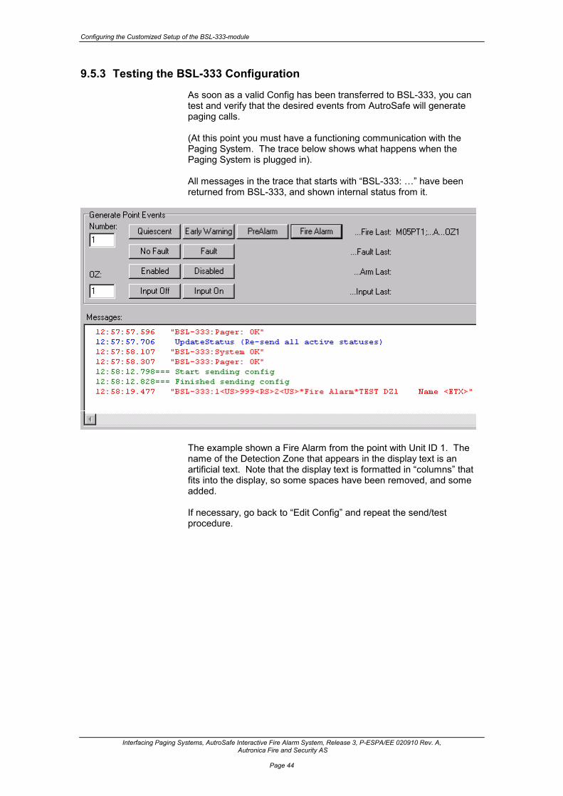
As soon as a valid Config has been transferred to BSL-333, you can test and verify that the desired events from AutroSafe will generate paging calls. (At this point you must have a functioning communication with the Paging System. The trace below shows what happens when the Paging System is plugged in). All messages in the trace that starts with “BSL-333: …” have been returned from BSL-333, and shown internal status from it.
The example shown a Fire Alarm from the point with Unit ID 1. The name of the Detection Zone that appears in the display text is an artificial text. Note that the display text is formatted in “columns” that fits into the display, so some spaces have been removed, and some added. If necessary, go back to “Edit Config” and repeat the send/test procedure.

Verifying the Customised Setup of the BSL-333-module
Interfacing Paging Systems, AutroSafe Interactive Fire Alarm System, Release 3, P-ESPA/EE 020910 Rev. A, Autronica Fire and Security AS
Page 45
10. Verifying the Customised Setup of the BSL-333-module
10.1 Introduction
Cable XBA-055
Cable XJA-037
Power
Fire Brig. recvd.
Fire vent. activ.
Fire ext.. acktivated
0
A L A RMA L A RMA L A RMA L A RM
?
C
987
654
321
Silence buzzer
Silence sounders
Reset
More Alarms
Prewarning
Early warning
System faultFunction disabled
Test
Fault
Self Verify
BSL-333
The procedure verifies that the customised setup is successful. The Pager Tester is used for this purpose. This chapter includes the following: • Connecting the cables (refer to chapter 3.4.1 and 3.4.3) • Verifying the customised setup of the BSL-333 module
10.2 Verification Procedure It is possible to test the BSL-333 without having a working paging system. • Connect a PC to BSL-333 port 2. • Run the PagerTest.exe program. • Open the serial port with correct settings:
Select the “Receive” tab:
Computer with Pager Test Program

Verifying the Customised Setup of the BSL-333-module
Interfacing Paging Systems, AutroSafe Interactive Fire Alarm System, Release 3, P-ESPA/EE 020910 Rev. A, Autronica Fire and Security AS
Page 46
• Click the button “Start ESPA Receiving”. You will see a number of “Receiving : Poll…” messages, and whenever something is to be paged, a decoded message.

Verifying the paging functionality with a complete
system setup
Interfacing Paging Systems, AutroSafe Interactive Fire Alarm System, Release 3, P-ESPA/EE 020910 Rev. A, Autronica Fire and Security AS
Page 47
11. Verifying the paging functionality with a complete system setup
11.1 Introduction
Cable XBA-055
Power
Fire Brig. recvd.
Fire vent. activ.
Fire ext.. acktivated
0
A L A RMA L A RMA L A RMA L A RM
?
C
987
654321
Silence buzzer
Silence sounders
Reset
More Alarms
Prewarning
Early warning
System fault
Function disabledTest
Fault
Self Verify
BSL-333EAU-321 Paging System
The procedure provides information on how to verify the paging functionality with a complete system setup. The AutroSafe system is used to activate various events, i.e. fire alarms, prealarms, fault messages, texts etc.
The procedure includes the following: • Connecting the cable between AutroSafe and Port 1 on the BSL-
333 module (refer to chapter 3.4.1)
• Connecting the cable between Port 2 on the BSL-333 module and the paging system (Normally the cable is delivered with the paging system. BSL-333 has screw connectors).
• Verifying the complete system setup (refer to Verification Procedure on next page).
NOTE: Before activating events by means of the AutroSafe Interactive Fire Alarm System, disable:
the signal to the Fire Brigade sounders voice alarms other audible / visual indicators output controls activating fire doors and ventilation

Verifying the paging functionality with a complete system setup
Interfacing Paging Systems, AutroSafe Interactive Fire Alarm System, Release 3, P-ESPA/EE 020910 Rev. A, Autronica Fire and Security AS
Page 48
11.2 Verification Procedure
• Verify that the following AutroCom events can be paged:
o fire alarms o prealarms o faults o technical alarms from I/O units
• Verify that the display on the different pagers show the correct
information (name of a Detection Zone and Tag Names /point information, plus general fault texts).
• Verify that each pager receives the correct type of message according to what has been configured.
• Verify group identity (number plan for the pagers) according to what
has been configured.
• Verify that the Beep Codes are correct according to what has been configured for Alarm, Prealarm and Faults.
NOTE: Before activating events by means of the AutroSafe Interactive Fire Alarm System, disable:
the signal to the Fire Brigade sounders voice alarms other audible / visual indicators output controls activating fire doors and ventilation

Interfacing Off-site GSM Telephones (SMS Messages)
Interfacing Paging Systems, AutroSafe Interactive Fire Alarm System, Release 3, P-ESPA/EE 020910 Rev. A, Autronica Fire and Security AS
Page 49
12. Interfacing Off-site GSM Telephones (SMS Messages)
12.1 Introduction To be able to send SMS messages to GSM telephones additional equipment is required: AutroTel Module BSL-334. This module provides ESPA interface (input) and can transmit SMS via a built-in GSM telephone.
12.2 Cable Connections The test cable XJ-A037 (Port2 to PC) can be used directly. Communication Cable XJA-037 is used between the BSL-334 module and Port 2 on the BSL-333 module.
Connector computer to BSL-333, Port 2

Interfacing Off-site GSM Telephones (SMS Messages)
Interfacing Paging Systems, AutroSafe Interactive Fire Alarm System, Release 3, P-ESPA/EE 020910 Rev. A, Autronica Fire and Security AS
Page 50
12.3 Configuration for AutroTel Module BSL-334 The standard BSL-333 Configuration must be modified as follows: • Modify Settings[1]; Alphabet=G // G = GSM
characters • Modify Settings[1]; DisplaySize=96 // Max 96 chars to
BSL-334 • Remove Settings[1]; LineLength // Let telephone do word
wrap • Go through all Events[]; and set Transm=1 // GSM has reliable
transmission IMPORTANT: Go through all Events[] and make certain that no display text message starts with a “*”. You can for example insert a “ “ (space) in front of the *. (SMS messages starting with * is displayed as an empty message.) At the same time, also remove any line break characters like “-“ (hyphen) and “|” (bar), as a GSM telephone does word-wrap locally according to it’s own display size and font. (It is possible to use the “|” (bar) as a new-line control to improve readability, especially in the Fault messages.)

Troubleshooting
Interfacing Paging Systems, AutroSafe Interactive Fire Alarm System, Release 3, P-ESPA/EE 020910 Rev. A, Autronica Fire and Security AS
Page 51
13. Troubleshooting
13.1 Self Monitoring The Wireless Pager functionality involves a number of hardware boxes and wires that may fail.
The BSL-333 implementation tries to monitor and report as much problems as possible.
Hardware in fault Monitored by Reporting AutroSafe EAU-321 serial board Monitored by
AutroSafe software. Detected within 10 seconds.
Fault on AutroSafe panel, ”Communication error” ”Loss of communication”
RS232 wiring from As above As above EAU-321 to BSL-333 Monitored by BSL-333. Sends message to selected
pagers: ”Pager status: AutroSafe Communication FAULT”
BSL-333 hardware AutroSafe, as above AutroSafe panel, as above
AutroSafe Panel
AutroCom via
EAU-321
BSL-333ESPA
Interface Module
Wireless Paging System
with ESPA interface
External Link
AutroComLink

Troubleshooting
Interfacing Paging Systems, AutroSafe Interactive Fire Alarm System, Release 3, P-ESPA/EE 020910 Rev. A, Autronica Fire and Security AS
Page 52
As the BSL-333 is located inside the AutroSafe cabinet, it’s most likely that hardware problems occur on the outside of BSL-333. BSL-333 then can use AutroSafe’s panel for fault reports.
Hardware in fault Monitoring Reporting RS232 wiring to Wireless Pager System
Monitored by BSL-333 software. Detected within 10 seconds.
Fault indicated on AutroSafe panel, ”Communication error” ”Protocol Converter Fault”, Data 1, 1, 15 or Data 1, 2, 9 (separate table)
Wireless Pager System As above As above box Wireless Pager system internal tests,
can give ”busy” status or ”transmitter failure”
Fault on AutroSafe panel, ”Communication error” ”Protocol Converter Fault”, Data 1, 2, 2 (separate table)
AutroSafe displays information of “Protocol Converter Fault”. Data explanation.
Value 1 Error type: 1 = Communication problem Value 2 Pager Application status 1 = No Communication at all (startup problem) 2 = Transmission problem after a period of working communication. 3 = Pager Queue Full. Too many fire system events in a short time. Value 3 Status of low level communication with Pager transmitter 1 = Transmission failed due to checksum error 2 = Pager BUSY. (Try again later) 3 = Message rejected due to unknown information field/value. 8 = ACK Timeout. Pager system ignored message. (polling works) 9 = Paging system does not respond to polling (broken wire? power down?) 15 = System power up status; there has been no contact with pager after startup.
Example: “Communication error” “Protocol Converter Fault” Data 1.1.15
System power up status, there has been no contact with pager after startup No communication Communication problem

Troubleshooting
Interfacing Paging Systems, AutroSafe Interactive Fire Alarm System, Release 3, P-ESPA/EE 020910 Rev. A, Autronica Fire and Security AS
Page 53
13.2 Quick system overview The LEDs of the BSL-333 Module gives immediate info:
13.2.1 AutroSafe communication
• 1RX should flash at least every 3 seconds, indication data received from EAU-321. If constantly dark, check wiring. Also refer to “Missing communication”, chapter 13.3.1.2. If flashing, but problems, the port settings (baudrate etc.) may be the problem.
• 1TX should flash at least every 3 seconds, indicating transmission from BSL-333 to AutroSafe. If constantly dark, the ESPA program inside BSL-333 is not executing properly.
The self-monitoring of the AutroCom link by AutroSafe and BSL-333 is based on messages sent one way, and acknowledges going the other way. Thus, both data paths must be OK before the link is reported OK. In the case where wiring is OK, but port settings (baudrate etc.) is wrong, both ends will transmit periodically, causing both 1RX and 1TX to flash in a “normal” rate. For advanced debugging, see separate chapter on AutroCom faultfinding.
13.2.2 Pager communication
• 2RX should flash at least every 0.5 seconds, indicating that the pager system responds to polling by BSL-333. If constantly dark, there could either be a wiring problem, or a port settings problem.
• 2TX should flash at least every 0.5 seconds, indicating transmission from BSL-333 to the pager system. If constantly dark, the ESPA program inside BSL-333 is not executing properly.
The self-monitoring of the AutroCom link by BSL-333 is based on polling messages sent one way, and acknowledges going the other way. Thus, both data paths must be OK before the link is reported OK. In the case where wiring is OK, but port settings (baudrate etc.) is wrong, only BSL-333 will transmit periodically, causing only 2TX to flash in a “normal” rate. For advanced debugging, see separate chapter on Paging system faultfinding.

Troubleshooting
Interfacing Paging Systems, AutroSafe Interactive Fire Alarm System, Release 3, P-ESPA/EE 020910 Rev. A, Autronica Fire and Security AS
Page 54
13.2.3 “Check wiring”
• A classic problem with RS232 links is that the RX and TX signals are connected RX-RX and TX-TX. Plain wire breaks (bad contacts) are also possible, of course. It’s easy to verify RS232 signals using a Voltmeter, see below. NOTE: Measure the RX and TX signals at both ends of a link!
• All RS232 TX (output) signals should be NEGATIVE in the range –6V to –12V, with –8V as typical and you may even see –3V to –5V on some portable PCs. The voltage does not change much on a multimeter during data transmissions (which temporarily goes to PLUS 6V to 12V). A TX signal can’t drive much current, and the voltage may drop a little (one or more Volts) when connected to a RX input.
• A non connected RS232 RX (input) is typically below 0.5 V, and fluctuates when read.
• Note GND connections on the BSL-333 Module. All 3 GNDs are isolated from each other inside the BSL-333 Module. You must connect each of them to the proper external system, and do NOT strap them together nor “share” GND from another box. This applies also to voltage measurements; they are valid only relative to the same port’s GND signal, no other!
13.2.4 “BSL-333 program not executing properly”
This is an abnormal situation. Return the BSL-333 to the factory. NOTE: The BSL-333 Module can accidentally be configured into “ADE fixed program mode” different from “Off”. In this case the BSL-333 Module will be running a built-in level converter program, which basically receives on one port, and sends on the other, possibly converting baudrates and/or electric interface. The port 1 LEDs and port 2 LEDs flashes in pairs RX/TX. Run KDCFG.EXE and check the “ADE” setting before giving up the unit!

Troubleshooting
Interfacing Paging Systems, AutroSafe Interactive Fire Alarm System, Release 3, P-ESPA/EE 020910 Rev. A, Autronica Fire and Security AS
Page 55
13.3 AutroCom problems on the AutroSafe side
13.3.1.1 Verify communication
AutroCom starts running during the “Start initialization” operation. That is, it is running when the AutroSafe display shows “Panel is not initialized”. When AutroCom is running it sends a message $0BxxGxxxx every two seconds. This is easy to verify with the AutroCom Test program, or a plain Windows HyperTerminal.
AutroSafe Panel
AutroCom via
EAU-321
BSL-333ESPA
Interface Module
Wireless Paging System
with ESPA interface
External Link
AutroComLink
PC with
AutroCom Test

Troubleshooting
Interfacing Paging Systems, AutroSafe Interactive Fire Alarm System, Release 3, P-ESPA/EE 020910 Rev. A, Autronica Fire and Security AS
Page 56
13.3.1.2 Missing communication
AutroSafe expects the external computer to log on within a few seconds after startup. If no logon occurs, the AutroSafe display gives a “Fault warning”, “Other faults”, with the name text of the AutroCom link (name as entered in AS Config). Press AutroSafe’s ENTER button on this message, and you will see fault info “Loss of communication”. The fact that this error message is generated indicates that configuration and serial hardware is present in AutroSafe. Missing communication can have several reasons: • Wrong port set up in AutroSafe Config.
Re-check the port numbering plan… • EAU-321 not set up correctly.
Check that the flat cable running from EAU-321 is connected on port 1/2 and is turned correctly (red line close to pin 1 in connector, “up” on EAU-321, “down” on screws). Check that all jumpers are correct: See drawing on next page.
• Communication parameter (baud rate etc.) mismatch between AutroSafe and the external computer. This will show up in the AutroCom test program as garbage characters appearing with 2 seconds bursts.

Troubleshooting
Interfacing Paging Systems, AutroSafe Interactive Fire Alarm System, Release 3, P-ESPA/EE 020910 Rev. A, Autronica Fire and Security AS
Page 57
The table below gives an overview of the jumper settings for the Serial Port Communication Board EAU-321. Jumpers J5 and J6: J5 and J6 must be set to interrupt 2 and 5.
Jumpers J8 (interrupt) J8 must be set to interrupt 7 and R.
Jumpers J9, J10 and J11 (interrupt) All ports must be set to interrupt 7. Jumper J7 (board address) Jumper in position A and B must be set to In. This setting applies to all communication boards. Gives board address 100h.
CBA
I/O header Port 3 and 4
J5
J6
J7
Serial Port Communication Board EAU-321
J8J9
J10J11
Port 1
Port 2I/O header Port 1 and 2
Addressjumpers
Port 4
Port 3
I/O header Port 3 and 4
J5
J6
J7
Serial Port Communication Board EAU-321
J8J9
J10J11
Port 1
Port 2I/O header Port 1 and 2
Addressjumpers
Port 4
Port 3
J5
J6
J7
Serial Port Communication Board EAU-321
J8J9
J10J11
Port 1
Port 2I/O header Port 1 and 2
Addressjumpers
Port 4
Port 3
15 12 11 10 7 6 5 4 3 2 R15 12 11 10 7 6 5 4 3 2 R
15 12 11 10 7 6 5 4 3 2 R15 12 11 10 7 6 5 4 3 2 R
TXRXCTDCDSR1123456
TXRXCTDCDSR1123456

Troubleshooting
Interfacing Paging Systems, AutroSafe Interactive Fire Alarm System, Release 3, P-ESPA/EE 020910 Rev. A, Autronica Fire and Security AS
Page 58
Connections on Terminal Blocks X1 and X2 (if used)
2018161412108642
191715131197531
NC
DSR 2RTS 2CTS 2RI 2
RXD 2TXD 2DTR 2GND
DCD 2
DSR 1RTS 1CTS 1RI 1NC
DCD 1RXD 1TXD 1DTR 1GND
Port 2
Port 1
X1
Terminal Block X2
Terminal Block X1

Troubleshooting
Interfacing Paging Systems, AutroSafe Interactive Fire Alarm System, Release 3, P-ESPA/EE 020910 Rev. A, Autronica Fire and Security AS
Page 59
13.3.1.3 Verify configuration
AutroSafe writes some trace during system start-up to the serial port on the EAC-300 that is used for loading of AutroSafe Config. The port runs on 9600 baud, 8 bit, no parity, 1 stop bit. Run a standard Windows HyperTerminal connected to this port. (Uses the same connections as used when downloading AutroSafeConfig). Hardware detection takes place immediately after system restart. You will find two lines of text describing the status of possible AutroCom channels. As the AutroSafe system starts up, more text is written to the terminal port. Among the printout here you will find a line “[autrocom99-P1] Data protocol running …” [autrocom38-P1] shows both the Unit_ID of the channel (38), plus the port number of EAU-321 (P1). Unit_ID is the number you will find in AS Config when you select an AutroCom entry and inspect the details in the right part of the screen. (The number is assigned dynamically). This text indicates that the AutroCom configuration and EAU-321 hardware is present.
AutroSafe Panel
AutroComvia
EAU-321
BSL-333ESPA
Interface Module
Wireless Paging System
with ESPA interface
External Link
AutroComLink
PC with
AutroCom Test
Hyperterminal Test Program
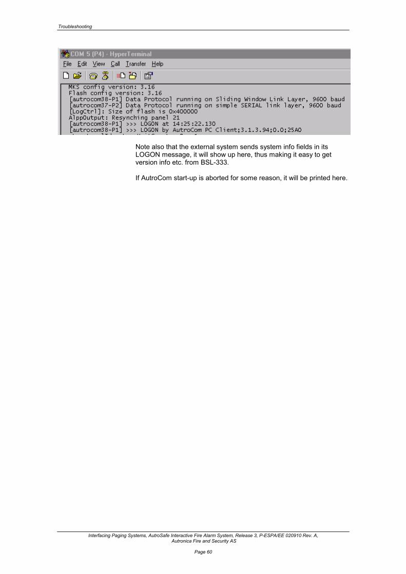
Troubleshooting
Interfacing Paging Systems, AutroSafe Interactive Fire Alarm System, Release 3, P-ESPA/EE 020910 Rev. A, Autronica Fire and Security AS
Page 60
Note also that the external system sends system info fields in its LOGON message, it will show up here, thus making it easy to get version info etc. from BSL-333. If AutroCom start-up is aborted for some reason, it will be printed here.

Troubleshooting
Interfacing Paging Systems, AutroSafe Interactive Fire Alarm System, Release 3, P-ESPA/EE 020910 Rev. A, Autronica Fire and Security AS
Page 61
13.4 Testing ESPA output from BSL-333
It’s possible to test the BSL-333 without having a working Paging System. • Connect a PC to BSL-333 port 2 • Run the PagerTest.exe program. • Open the serial port with correct settings:
AutroSafe Panel
AutroCom via
EAU-321
BSL-333ESPA
Interface Module
Wireless Paging System
with ESPA interface
External Link
AutroComLink
PC with
PagerTest (receive)

Troubleshooting
Interfacing Paging Systems, AutroSafe Interactive Fire Alarm System, Release 3, P-ESPA/EE 020910 Rev. A, Autronica Fire and Security AS
Page 62
Select the “Receive” tab: • Click the button “Start ESPA Receiving”. You will see a number of “Receiving : Poll…” messages, and whenever something is to be paged, a decoded message.

Troubleshooting
Interfacing Paging Systems, AutroSafe Interactive Fire Alarm System, Release 3, P-ESPA/EE 020910 Rev. A, Autronica Fire and Security AS
Page 63
13.5 Testing ESPA input to Paging System
It’s possible to test the Paging System stand-alone. This is very useful to verify the baud-rate etc. (when communication problems), and that the number plan of the pocket receivers is correct (when functional problems). • Connect a PC to the Paging System • Run the PagerTest.exe program. • Open the serial port with correct settings
(see screenshot in the previous pages)
AutroSafe Panel
AutroCom via
EAU-321
BSL-333ESPA
Interface Module
Wireless Paging System
with ESPA interface
External Link AutroCom
Link
PC with
PagerTest (send)
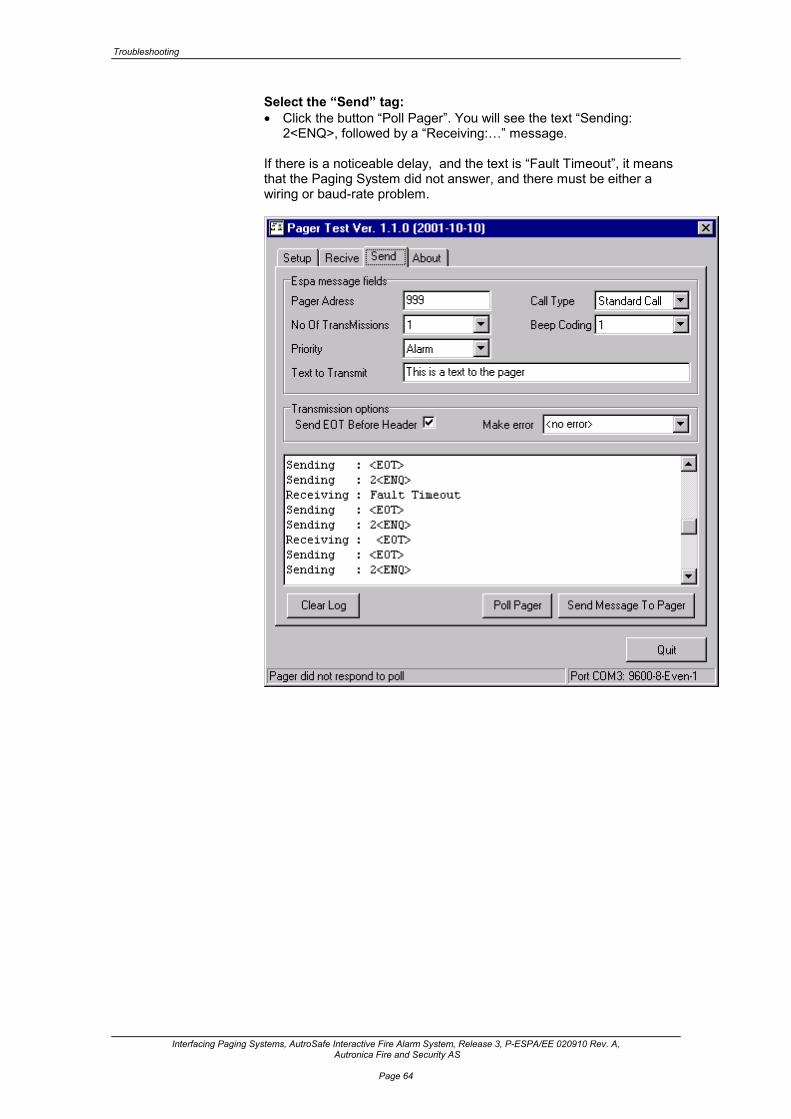
Troubleshooting
Interfacing Paging Systems, AutroSafe Interactive Fire Alarm System, Release 3, P-ESPA/EE 020910 Rev. A, Autronica Fire and Security AS
Page 64
Select the “Send” tag: • Click the button “Poll Pager”. You will see the text “Sending:
2<ENQ>, followed by a “Receiving:…” message. If there is a noticeable delay, and the text is “Fault Timeout”, it means that the Paging System did not answer, and there must be either a wiring or baud-rate problem.

Troubleshooting
Interfacing Paging Systems, AutroSafe Interactive Fire Alarm System, Release 3, P-ESPA/EE 020910 Rev. A, Autronica Fire and Security AS
Page 65
As soon as Polling works, you can start sending messages to the pocket receivers. Fill in the “Pager Address” field, and enter a suitable display text. Then click the button “Send Message To Pager”.
Normally the response is “Receiving: <ACK>”, which means positive acknowledge. You may also get negative acks: 1<NAK> means a transmission error (bit-error). 2<NAK> means busy – try later. 3<NAK> means that the message was received OK, but the content is not understood.

BSL-333- Configuration Tables
Interfacing Paging Systems, AutroSafe Interactive Fire Alarm System, Release 3, P-ESPA/EE 020910 Rev. A, Autronica Fire and Security AS
Page 66
14. BSL-333- Configuration Tables
14.1 The Settings table The Settings table has only one line. Settings[1]; Char8=ÆØÅæøå; Settings[1]; Char7=[/]|; Settings[1]; Alphabet=7; Upper=0; Settings[1]; DisplaySize=120; LineLength=12;
Field (Example)
Values Explanation
Char8 ÆÅØæøå Char8 is used together with Char7 for character (alphabet) translation between a PC’s 8-bit international character set and a pager’s 7-bit national character set. See tables in Appendix for various European languages. Char8 must hold characters with ASCII value between 0xC0(À) and 0xFF(ÿ). Example value: Norwegian national characters
Char7 [/]| Char7 contains the 7-bit character that is to be used for the characters defined in Char8. The first char in Char8 is replaced by the first char in Char7, and so on. Note the example; Char8 and Char7 are put on separate lines, and then it’s easy to se a one-to-one translation result. Example value: Norwegian character generator locations
Alphabet Main control of Character set translation: 8 - No translation. 8-bit Windows character set used. 7 - The pager receiver uses a 7-bit character set. All 8-bit
characters are changed to their 7-bit counterpart (accents removed, e.g. “À” into “A”). In addition, national characters are translated according to the Char8 + Char7 settings.
G - GSM 03.38 character set. To be used with the BSL-334 ESPA-to-SMS interface. Gives some national characters – see appendix.
Upper Additional control over 7-bit Character set 0 - No change of character set. 1 - Lower case letters “a..z” are changed to upper case
letters “A..Z.” May be needed by some older receivers with 14-segment displays.
DisplaySize 120 This is the size of the largest display message the receiver can handle. If the text produced by BSL-333 becomes longer than this value, the message will be set to this size.

BSL-333- Configuration Tables
Interfacing Paging Systems, AutroSafe Interactive Fire Alarm System, Release 3, P-ESPA/EE 020910 Rev. A, Autronica Fire and Security AS
Page 67
If the text produced by BSL-333 is shorter, just the actual text is sent. Some older paging systems requires an exact number of characters, say 16.
LineLength 12 The physical display of a receiver is usually divided into lines. To make text more easy to read, BSL-333 can “word-wrap” the text so that words start on a new line if they are too long for the previous one. If this field is left out (or set to 0), no word-wrap takes place. Also, if the wrapped text becomes longer than DisplaySize due to the added spaces, no word-wrap will take place. Special characters: A hyphen “-“ can be inserted in a text to divide the text across two lines in a controlled way. Example: “Communicat-ion”. A vertical bar “|” can be used as a “newline” character. Example: “... |Message= …” makes “Message” start on a new line.

BSL-333- Configuration Tables
Interfacing Paging Systems, AutroSafe Interactive Fire Alarm System, Release 3, P-ESPA/EE 020910 Rev. A, Autronica Fire and Security AS
Page 68
14.2 The Events table Each Event consists of two parts: • The identification of the event,
which is implemented very close to the AutroCom protocol’s messages
• The expression of the event, which is how the pocket receiver will behave when paged with this event. These values are close to the ESPA protocol.
Events[1]; Func=05; State=A; Events[1]; Priority=1; Beeps=3; Transm=3; Events[1]; Text=*Fire Alarm* <DZ> <UI>;
Field (Example)
Values Explanation
Func 05 AutroCom: The AutroCom message (function number) that will be monitored. See the Func/State table below for values.
State A AutroCom: A character sub-field in the monitored AutroCom message. See the Func/State table below for values. If the field is left out, or set to 0, it will match ALL states.
Number 1 AutroCom: A numeric sub-field in the monitored AutroCom message. Alternative name of the “State” field.
Priority 1 ESPA: Priority of the pager call. The priority is used both internally in the BSL-333, and in the pager system. 1 = Alarm 2 = High 3 = Normal
Beeps 5 ESPA: Beep coding. Depending on the pager brand, this can either be number of beeps, or it can be an index into a table of pre-set beep patterns. This code may also be used to control a vibrator in the receiver. Values are 1 to 9.
Transm 3 ESPA: Number of radio transmissions. The radio transmission from the paging system’s transmitter to the pocket receivers may be lost due to noise from other electric systems, or the user being in a location with poor antennae coverage. To improve reliability, high priority pagings should also be set up with 2 or 3 radio (re-) transmissions.
Type 3 ESPA: Call Type. 3 = Standard Call, this is the usual value for Display paging. 4 = (ascom Telecourier: Alarm Call)
Text *Fire Alarm* <DZ> <UI>
ESPA: Display Message. The display text consists of a fixed “background” text, with dynamic fields in brackets < > that will be replaced with actual texts/numbers for each paged event. See separate description.

BSL-333- Configuration Tables
Interfacing Paging Systems, AutroSafe Interactive Fire Alarm System, Release 3, P-ESPA/EE 020910 Rev. A, Autronica Fire and Security AS
Page 69
14.3 The Receivers table There is one line in the Receivers table for each pocket receiver that shall be notified about events in the Fire System. // Owner: N.N. Receivers[1]; Address=100; Events=0; OZ=0;
Field (Example
) Values
Explanation
Address 100 ESPA: Call address. The pocket receiver’s address in the paging system. The address is stored as a variable length text: - the address can be any number of digits, e.g. a telephone number when used with BSL-334 GSM/SMS - the address can contain letters, used by some pagers for group addresses.
Events 0 1,2,4
Paging requirement: A list of Events that this receiver shall know about. This way some pagers receive just fire-/pre-alarms, while others also can receive fault messages. The values are the index (tag) of Event table entries; i.e. the numbers inside the Events[..] brackets. - A value of 0 (or left out) means “page all events”.
OZ 0 2,3
Paging requirement: Limit paged events to those occurring in specified OZs only. Can be used to create e.g. per-building pagings. (Used in very large systems). Note: Grouping by OZ only works for the Fire alarm events. The OZs listed here must be the closest “owner” of a point; it’s not possible to select OZs in the middle of a deeper hierarchy. - A value of 0 (or left out) means “page all OZs”.

BSL-333- Configuration Tables
Interfacing Paging Systems, AutroSafe Interactive Fire Alarm System, Release 3, P-ESPA/EE 020910 Rev. A, Autronica Fire and Security AS
Page 70
14.4 Func/state for the Events table The Events table has a flexible framework to be able to handle various information in a systematic way, but only a limited number of combinations have been implemented. The table below shows the valid combinations between “Func”, “State” and display text “<..>”. The format of the “<..> fields are described in a separate table.
Func State / number
DisplayText Comment
05 A *Fire Alarm* <DZ> <UI> Point message: Fire Alarm 05 P FirePreAlarm <DZ> <UI> Point Message: Prealarm 05 Y FireEWarning <DZ> <UI> Point Message: Early Warning
(normally not used) 05 any
letter any Point Message: Any other letter
from the OP_EqPointMsg’s AlarmState parameter can be used for special purposes!
03 0 (zero or empty)
FireSysFault Unit= <UI> |Message= <CL>: <RE>
Unit message: Fault message. Any fault presented on AuroSafe’s display can be paged with fault texts in the local language. - Normally sent only to technical staff pagers.
03 P,D FireSysFault Unit= <UI> |Message= <CL>: <RE>
Unit message: Fault message. The P and D states refer to Point and DZ respectively. - Use of these states are optional, but can be used to give point faults to pagers monitoring only point alarms.
00 1 Pager Status AutroSafe communicat-ion <ST=FAULT,OK>
BSL-333 internal message(s): It may be nice to know if AutroSafe and/or the AutroCom link is operative.
34 0 (zero or empty)
Techn. Alarm <UI> |Status=<ST=OFF,ON>
FPE message: Inputs of FPE units can be used as Technical Alarms.
34 Unit Id no
any FPE Message: If a system has many FPEs, and just a few of them shall cause paging, it’s possible to create one event for each of them, and identify the FPE by entering it’s Unit Id number in the Number field. In this case the status text can vary also, e.g <ST=CLOSED,OPEN>, <ST=COLD,HOT>…
14.4.1 Search order for the Events table
As indicated above, it’s possible to enter one function several times in the Events table. The table will be searched from the top downwards until a match is found. It’s possible to enter one or more specific func/state combinations, followed by an entry with empty state (Empty means “match all”). This feature can be used to separate Point faults from all faults, or to have dedicated texts for some Technical Alarms, and let the remaining alarms share a common text.

BSL-333- Configuration Tables
Interfacing Paging Systems, AutroSafe Interactive Fire Alarm System, Release 3, P-ESPA/EE 020910 Rev. A, Autronica Fire and Security AS
Page 71
14.5 Display Texts
14.5.1 Dynamic <..> fields in Display Texts.
Example display text: “*Fire Alarm* <DZ> <UI>” The dynamic fields can be used like this.
Func Field Comment 05 <DZ> Point status messages: Detection Zone name text.
Up to 34 characters, fetched from AutroSafe. 03 05 34
<UI> General “Unit Id”. Name (name tag) of point, FPE, or any System unit in Fault. Up to 24 characters, fetched from AutroSafe.
03 <CL> Fault Class text. Up to 40 characters, fetched from AutroSafe (in it’s menu language).
03 <RE> Fault Reason text Up to 40 characters, fetched from AutroSafe (in it’s menu language). Note that a Reason has meaning only together with its Class.
00 34
<ST=..> Status text. Any length, fetched from BSL-333 config. A “status” is a numeric value, starting with 0, then 1, … Func 00: (internal faults) 0=FAULT, 1= OK Func 34: (FPE input) 0=Off (input open), 1= On (input closed) To give meaningful texts (in local language), it’s possible to make a list of texts. Example: <ST=CLOSED,OPEN> can be used for FPE statuses “off” and “On” in “Text=Door <UI> is <ST=CLOSED,OPEN>;” If a certain status shall NOT cause paging, use an empty text (just comma “,”). Example: <ST=FAULT,> <ST=,OPEN>
Length modifier for dynamic fields: When working with small displays it can be desirable to control the width of each field. All dynamic fields that receive texts from AutroSafe can be forced to a preset length using the syntax <XX:NN>. For example <DZ:15> or <CL:10>.<RE:20>. This way some info can be given from all fields.

BSL-333- Configuration Tables
Interfacing Paging Systems, AutroSafe Interactive Fire Alarm System, Release 3, P-ESPA/EE 020910 Rev. A, Autronica Fire and Security AS
Page 72
14.5.2 Considerations for Display Texts
Display texts must be edited per installation due to: • Local language.
Each country should make a Config “master” in its own language that can be re-used in future installations.
• Customer’s other use of pagers. A paging system can be controlled from a number of sources like telephones, Nurse Call systems, intercoms, plus numerous technical alarms. The customer may have some requirements regarding how each sub-system shall identify its messages. (The standard BSL-333 config contains the word “Fire” in all messages.)
• Size of display. The start word(s) of a message should give useful information that fits into one (physical) display line. The standard BSL-333 config contains texts that fit within 12 characters.

Appendix
Interfacing Paging Systems, AutroSafe Interactive Fire Alarm System, Release 3, P-ESPA/EE 020910 Rev. A, Autronica Fire and Security AS
Page 73
15. Appendix
15.1 Verifying the Communication between AutroSafe and the BSL-333 Module using the default BSL-333 Configuration
15.1.1 Introduction
Before customizing the configuration of the BSL Module, it is possible to verify that the cabling and communication between AutroSafe and the BSL-333 module is successful so that BSL-333 operates correctly with AutroSafe. The verification procedure is based on the default configuration of the BSL-333 Module, which is downloaded at the factory. The procedure requires a computer and the ESPA service pack (AS-SERVPACK).
BSL-333Power
Fire Brig. recvd.
Fire vent. activ.
Fire ext.. acktivated
0
A L A RMA L A RMA L A RMA L A RM
?
C
987
654321
Silence buzzer
Silence sounders
Reset
More Alarms
Prewarning
Early warning
System faultFunction disabled
Test
Fault
Self Verify
The procedure is done by activating a fire alarm or fault from an easily accessable detector or manual callpoint.
The verification procedure is successful when the message on the computer screen is identical to the message shown on the Fire Alarm Control Panel’s display. Typically, this will be the name of the detection zone (Tag Name).
15.1.2 Preparations – AutroSafe Configuration
Note that the AutroSafe system must be configured according to the specific installation and the AutroCom type for the serial port must be set to SlidingWindow. Refer to chapter 7.
NOTE: Before activating a fire alarm or fault, disable:
the signal to the Fire Brigade sounders voice alarms other audible / visual indicators output controls activating fire doors and ventilation
Computer with ESPA Test Program

Appendix
Interfacing Paging Systems, AutroSafe Interactive Fire Alarm System, Release 3, P-ESPA/EE 020910 Rev. A, Autronica Fire and Security AS
Page 74
15.1.3 Verification Procedure
• Connect the BSL-333 to AutroSafe’s EAU-321 board. No custom BSL-333 Config is loaded yet! (If this test is run after a custom BSL-333 Config has caused problems: Load the standard English Config found on the BSL-333 installation CD-ROM).
• Connect a computer to BSL-333’s port 2 using the test cable XJA-037.
• On the computer, start the PagerTest program. o Select the COM port where the XJA-037 cable is connected. o Fill in communications parameters: Default BSL-333 settings
from factory are 9600 baud, 8 bit, no parity, 1 stop bit.
• Click on the PagerTest program’s “Receive” tab. The check-box “Pagings only” must be active . Click the button “Start Espa Receiving”.
• Do an action in AutroSafe that shall cause paging. o Either cause a fire alarm from a Manual CallPoint (may not be
possible in a running system) - or
o make a detector fault by removing a Detector nearby. The AutroSafe panel will show a Fire or a Fault after a short time. Note the DZ name of the Manual CallPoint or the Detector.
• Observe the message shown on computer screen (PagerTest). The message on the computer screen should be identical to the message shown on the Fire Alarm Control Panel’s display.

Appendix
Interfacing Paging Systems, AutroSafe Interactive Fire Alarm System, Release 3, P-ESPA/EE 020910 Rev. A, Autronica Fire and Security AS
Page 75
Message on computer screen:
Message on Fire Alarm Control Panel’s display:
Comments to the trace (in this example): • Pager address is 999. This is default in the standard English
Config for BSL-333 • The Pager Text is readable; you will find the “FireAlarm” or “Fault”
lead text, followed by related texts from AutroSafe. Fault texts will be in AutroSafe’s local language. (The texts are formatted for a default display size of 12 characters; you can make the texts prettier by changing the PagerTest’s field “Display Length” to 12.)
FIRE ALARMS 19:23Total: 3
1 <Detection Zone Name>2 CANTEEN3 WORKSHOP
FIRE ALARMS 19:23Total: 3
1 <Detection Zone Name>2 CANTEEN3 WORKSHOP
<Detection Zone Name>

Appendix
Interfacing Paging Systems, AutroSafe Interactive Fire Alarm System, Release 3, P-ESPA/EE 020910 Rev. A, Autronica Fire and Security AS
Page 76
15.1.4 Default BSL-333 Configuration // Config for BSL-333 ESPA Interface //------------------------------------ // // // General settings //---------------------------------------------- //Settings[1]; Char8=ÆØÅæøå; Settings[1]; Char7=[/]|; Settings[1]; Alphabet=8; Upper=0; Settings[1]; DisplaySize=120; LineLength=12; // // Events causing wireless paging: //-------------------------------- // - Detector statuses Events[1]; Func=05; State=A; Events[1]; Priority=1; Beeps=7; Transm=2; Events[1]; Text=*Fire Alarm* <DZ>; // Events[2]; Func=05; State=P; Events[2]; Priority=1; Beeps=5; Transm=2; Events[2]; Text=FirePreAlarm <DZ>; // Events[3]; Func=05; State=Y; Events[3]; Priority=2; Beeps=3; Transm=1; Events[3]; Text=Fire EarlyWa <DZ>; // // - Any Fault message / System faults Events[4]; Func=03; Events[4]; Priority=2; Beeps=1; Transm=1; Events[4]; Text=FireSysFault Unit= <UI> |Message= <CL>: <RE>; // // - Internal faults in the BSL-333 Events[5]; Func=00; Number=1; Events[5]; Priority=3; Beeps=1; Transm=1; Events[5]; Text=Pager Status AutroSafe communicat-ion <ST=FAULT,OK>; // // - Technical Alarms (FPE inputs) //Events[60]; Func=34; Number=0; //Events[60]; Priority=2; Beeps=3; Transm=1; //Events[60]; Text=Techn. Alarm <UI> <ST=OFF,ON>; // // List of pocket receivers, with event filter //---------------------------------------------- // Owner: N.N. Receivers[1]; Address=999; Events=0; OZ=0; // Owner: N.N. //Receivers[2]; Address=001; Events=1,2,3; OZ=0;

Appendix
Interfacing Paging Systems, AutroSafe Interactive Fire Alarm System, Release 3, P-ESPA/EE 020910 Rev. A, Autronica Fire and Security AS
Page 77
15.2 Screw Terminals on the BSL-333 Module The drawing below gives an overview of the screw terminals.
PR
OG
2TX
2RX
1TX
1RX
EXE
PWR
15.3 Character sets for AutroSafe AutroSafe supports a very limited set of national characters. Only Norwegian ÆØÅ and Swedish ÄÖ are supported. Ref . ASCII tables below. Note that Swedish characters have been assigned to the non-standard character positions 7/14 and 7/15.

Appendix
Interfacing Paging Systems, AutroSafe Interactive Fire Alarm System, Release 3, P-ESPA/EE 020910 Rev. A, Autronica Fire and Security AS
Page 78
15.4 ESPA 7-Bit character set (ISO 646) 0/ 1/ 2/ 3/ 4/ 5/ 6/ 7/
/0 NUL DLE SP 0 ... P ... p
/1 SOH DC1 ! 1 A Q a q
/2 STX DC2 " 2 B R b r
/3 ETX DC3 # 3 C S c s
/4 EOT DC4 $ 4 D T d t
/5 ENQ NAK % 5 E U e u
/6 ACK SYN & 6 F V f v
/7 BEL ETB ' 7 G W g w
/8 BS CAN ( 8 H X h x
/9 HT EM ) 9 I Y i y
/10 LF SUB * : J Z j z
/11 VT ESC + ; K ... k ...
/12 FF FS , < L ... l ...
/13 CR GS - = M ... m ...
/14 SO RS . > N ... n ...
/15 SI US / ? O _ o DEL

Appendix
Interfacing Paging Systems, AutroSafe Interactive Fire Alarm System, Release 3, P-ESPA/EE 020910 Rev. A, Autronica Fire and Security AS
Page 79
NATIONAL VERSIONS OF ISO 646 (Some languages have several “standard” mappings)
4/0 5/11 5/12 5/13 5/14 6/0 7/11 7/12 7/13 7/14
hexadecimal: 40 5B 5C 5D 5E 60 7B 7C 7D 7E
USA @ [ \ ] ^ ` | ~
Denmark Norway
@ Æ Ø Å ^ ` æ ø å ~
France à ° ç § ^ ` é ù è -
Germany § Ä Ö Ü ^ ` ä ö ü ß
Italy @ ° ç é ^ ù à ò è ì
Spain @ Ç Ñ ° ª ¿ ç ñ Ü ü
Sweden É Ä Ö Å Ü é ä ö å ü
15.5 GSM SMS character set (GSM 03.38)


Reader’s Comments
Interfacing Paging Systems, AutroSafe Interactive Fire Alarm System, Release 3, P-ESPA/EE 020910 Rev. A, Autronica Fire and Security AS
16. Reader’s Comments Please help us to improve the quality of our documentation by returning your comments on this manual: Title: Interfacing Paging Systems AutroSafe Interactive Fire Alarm System, Release 3, Ref. No.: P-ESPA/EE 020910 Rev. A
Your information on any inaccuracies or omissions (with page reference):
Please turn the page

Reader’s Comments
Interfacing Paging Systems, AutroSafe Interactive Fire Alarm System, Release 3, P-ESPA/EE 020910 Rev. A, Autronica Fire and Security AS
Suggestions for improvements
Thank you! We will investigate your comments promptly. Would you like a written reply? Yes No Name: ------------------------------------------------------------------------------------------------ Title: ------------------------------------------------------------------------------------------------ Company: ------------------------------------------------------------------------------------------------ Address: ------------------------------------------------------------------------------------------------ ------------------------------------------------------------------------------------------------ ------------------------------------------------------------------------------------------------ Telephone: ------------------------------------------------------------------------------------------------ Fax: ------------------------------------------------------------------------------------------------ Date: ------------------------------------------------------------------------------------------------
Please send this form to: Autronica Fire and Security AS N-7483 Trondheim Norway Tel: + 47 73 58 25 00 Fax: + 47 73 58 25 01
www.autronicafire.com/


Autronica Fire and Security AS is an international company, based in Trondheim, Norway and has a world-wide sales and service network. For more than 40 years Autronica’s monitoring systems have been saving lives and preventing catastrophes on land and at sea. Autronica Fire and Security’s most important business area is fire detection & security. Autronica Fire and Security stands for preservation of environment, life and property.
Quality Assurance Stringent control throughout Autronica Fire and Security assures the excellence of our products and services. Our quality system conforms to the Quality System Standard NS-EN ISO 9001, and is valid for the following product and service ranges: marketing, sales, design, development, manufacturing, installation and servicing of: • fire alarm and security systems • petrochemical, oil and gas instrumentation systems for monitoring and control
In the interest of product improvement, Autronica Fire and Security reserves the right to alter specifications according to current rules and regulations.
Autronica Fire and Security AS Fire and Security, Trondheim, Norway. Phone: + 47 73 58 25 00, fax: + 47 73 58 25 01. Oil & Gas, Stavanger, Norway. Phone: + 47 51 84 09 00, fax: + 47 51 84 09 99.
Autronica Industrial Ltd., Watford, United Kingdom. Phone: 1923 23 37 68, fax: 1923 22 55 77.
Visit Autronica Fire and Security's Web site: www.autronicafire.com

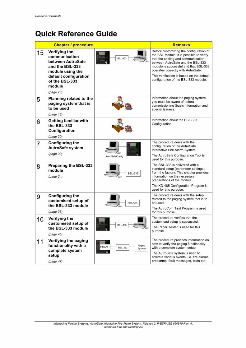
Reader’s Comments
Interfacing Paging Systems, AutroSafe Interactive Fire Alarm System, Release 3, P-ESPA/EE 020910 Rev. A, Autronica Fire and Security AS
Quick Reference Guide
Chapter / procedure Remarks
15 Verifying the communication between AutroSafe and the BSL-333 module using the default configuration of the BSL-333 module (page 73)
BSL-333Power
Fire Brig. recvd.
Fire vent. activ.
Fire ext.. acktivat ed
0
A L A R MA L A R MA L A R MA L A R M
?
C
987
654321
Silence buz zer
Sile nce sounde rs
Re set
More Ala rms
Pre warning
Early wa rning
System fa ultFunction disa bledTest
Fault
S elf Verify
Before customizing the configuration of the BSL Module, it is possible to verify that the cabling and communication between AutroSafe and the BSL-333 module is successful and that BSL-333 operates correctly with AutroSafe. This verification is based on the default configuration of the BSL-333 module.
5 Planning related to the paging system that is to be used (page 18)
Information about the paging system you must be aware of before commissioning (basic information and special issues).
6 Getting familiar with the BSL-333 Configuration (page 20)
Information about the BSL-333 Configuration.
7 Configuring the AutroSafe system (page 30)
AutroSafeConfig
Power
Fire Brig. re cvd.
Fire ve nt. activ.
Fire e xt.. a cktivat ed
0
A L A R MA L A R MA L A R MA L A R M
?
C
987
654
321
Silence buzzer
Silence sounders
Rese t
More Alarms
Prewarning
Early warning
Sys tem faultFunction disa bled
Tes t
Fault
Self Verify
The procedure deals with the configuration of the AutroSafe Interactive Fire Alarm System. The AutroSafe Configuration Tool is used for this purpose.
8 Preparing the BSL-333 module (page 34)
BSL-333
The BSL-333 is delivered with a standard setup (parameter settings) from the factory. This chapter provides information on the necessary preparations of the module. The KD-485 Configuration Program is used for this purpose.
9 Configuring the customised setup of the BSL-333 module (page 38)
BSL-333
The procedure deals with the setup related to the paging system that is to be used. The AutroCom Test Program is used for this purpose.
10 Verifying the customised setup of the BSL-333 module (page 45)
BSL-333Power
Fire Brig. recvd.
Fire vent. activ.
Fire ext.. acktivat ed
0
A L A R MA L A R MA L A R MA L A R M
?
C
987
654321
Silence buz zer
Sile nce sounde rs
Re set
More Ala rms
Pre warning
Early wa rning
System fa ultFunction disa bledTest
Fault
S elf Verify
The procedure verifies that the customised setup is successful. The Pager Tester is used for this purpose.
11 Verifying the paging functionality with a complete system setup (page 47)
Power
Fire Brig. recvd.
Fire vent. activ.
Fire ext.. acktivat ed
0
A L A R MA L A R MA L A R MA L A R M
?
C
987
654321
Silence buz zer
Sile nce sounde rs
Re set
More Ala rms
Pre warningEarly wa rning
System fa ultFunction disa bledTest
Fault
S elf Verify
BSL-333Paging SystemEAU-321
The procedure provides information on how to verify the paging functionality with a complete system setup. The AutroSafe system is used to activate various events, i.e. fire alarms, prealarms, fault messages, texts etc.