instructions, engineer‘s and illustrated …80800c+spanish.pdf · instructions, engineer‘s and...
TRANSCRIPT
INSTRUCTIONS, ENGINEER‘S AND ILLUSTRATED PARTSMANUAL
INSTRUCCIONES, MANUAL DEL INGENIERO Y LISTADOILUSTRADO DE PARTES
CLASS 80800 - SEWING MACHINES FOR CLOSING FILLED BAGSESTILO 80800 - MAQUINAS PARA CERRAR SACOS LLENADOS
MANUAL NO. / CATALOGO NR. G285FOR STYLES / PARA ESTILOS
80800C, D, E, H, HA

In addition to the instructions and to the mandatory rulesand regulations for accident prevention and environmentalprotection in the country and place of use of the machine/ unit, the generally recognized technical rules for safeand proper working must also be observed.
The instructions are to be supplemented by the respectivenational rules and regulations for accident prevention andenvironmental protection.
CATALOGO NR. G285EINSTRUCCIONES PARA MAQUINAS ESTILO 80800
Cuarta Edicion © 2003por Union Special GmbH Derechos Reservados en
todos los paísesImpreso en Alemania
INTRODUCCION
Este manual fue preparado para guiar al usuario en laoperación de maquinas de la serie 80800 y ayudar asimplificar la elaboración de los pedidos de los repuestos.
Este manual explica detalladamente los ajustes para laoperación de la maquina. Las ilustraciones sirven parademostrar los ajustes y las letras en referencia indicanlos puntos específicos discutidos.
Una cuidadosa atención a las instrucciones y lasprecauciones operando y ajustando estas maquinas leva a permitir mantener el mejor funcionamiento y laconfiabilidad que caracteriza las maquinas cerradorasde sacos de Union Special.
Los ajustes y precauciones son presentados ensecuencia para que se consiga una progresión lógica.La ejecución de algunos ajustes fuera de la secuenciapuede causar un efecto adverso para el funcionamientode otras partes relacionadas.
Este manual se comprende a base de la informaciónactual. Cambios en diseño y/o mejoras pueden significarleves modificaciones de la configuración de lasilustraciones o precauciones.
En las paginas siguientes se encuentran ilustraciones yterminologías usadas en la descripción de lasinstrucciones y las piezas de la maquina.
Adicionalmente a las instrucciones, las reglas yregulaciones obligatorias para prevenir accidentes y laprotección ambiental del país y lugar donde se encuentrala maquina/unidad, hay que considerar las reglas técnicaspara un trabajo seguro y adecuado.
Las instrucciones hay que complementarlas con lasrespectivas reglas y regulaciones nacionales contraaccidentes y protección del ambiente.
MANUAL NO. G285INSTRUCTIONS FOR 80800 SERIES MACHINES
Fourth Edition Copyright 2003by
Union Special GmbH Rights Reserved in All CountriesPrinted in Germany
PREFACE
This manual has been prepared to guide you whileoperating 80800 series machines and arranged to sim-plify ordering wear and spare parts.
This manual explains in detail the proper settings foroperation of the machines. Illustrations are used to showthe adjustments and reference letters are used to pointout specific items discussed.
Careful attention to the instructions and cautions foroperating and adjusting these machines will enable youto maintain the superior performance and reliability de-signed and built into every Union Special bag closingmachine.
Adjustments and cautions are presented in sequence sothat a logical progression is accomplished. Some adjust-ments performed out of sequence may have an adverseeffect on the function of the other related parts.
This manual has been comprised on the basis of avail-able information. Changes in design and / or improve-ments may incorporate a slight modification of configu-ration in illustrations or cautions.
On the following pages will be found illustrations andterminology used in describing the instructions and theparts for your machine.
2
3
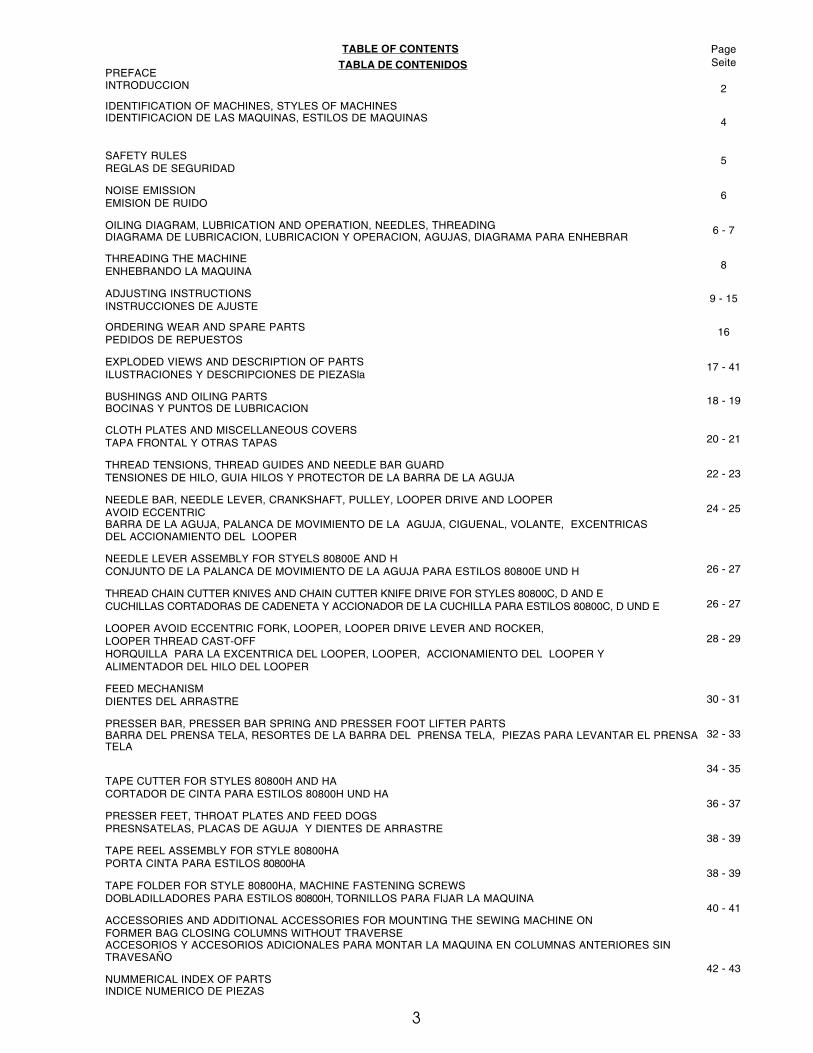
TABLE OF CONTENTS
TABLA DE CONTENIDOSPREFACEINTRODUCCION
IDENTIFICATION OF MACHINES, STYLES OF MACHINESIDENTIFICACION DE LAS MAQUINAS, ESTILOS DE MAQUINAS
SAFETY RULESREGLAS DE SEGURIDAD
NOISE EMISSIONEMISION DE RUIDO
OILING DIAGRAM, LUBRICATION AND OPERATION, NEEDLES, THREADINGDIAGRAMA DE LUBRICACION, LUBRICACION Y OPERACION, AGUJAS, DIAGRAMA PARA ENHEBRAR
THREADING THE MACHINEENHEBRANDO LA MAQUINA
ADJUSTING INSTRUCTIONSINSTRUCCIONES DE AJUSTE
ORDERING WEAR AND SPARE PARTSPEDIDOS DE REPUESTOS
EXPLODED VIEWS AND DESCRIPTION OF PARTSILUSTRACIONES Y DESCRIPCIONES DE PIEZASla
BUSHINGS AND OILING PARTSBOCINAS Y PUNTOS DE LUBRICACION
CLOTH PLATES AND MISCELLANEOUS COVERSTAPA FRONTAL Y OTRAS TAPAS
THREAD TENSIONS, THREAD GUIDES AND NEEDLE BAR GUARDTENSIONES DE HILO, GUIA HILOS Y PROTECTOR DE LA BARRA DE LA AGUJA
NEEDLE BAR, NEEDLE LEVER, CRANKSHAFT, PULLEY, LOOPER DRIVE AND LOOPERAVOID ECCENTRICBARRA DE LA AGUJA, PALANCA DE MOVIMIENTO DE LA AGUJA, CIGUENAL, VOLANTE, EXCENTRICASDEL ACCIONAMIENTO DEL LOOPER
NEEDLE LEVER ASSEMBLY FOR STYELS 80800E AND HCONJUNTO DE LA PALANCA DE MOVIMIENTO DE LA AGUJA PARA ESTILOS 80800E UND H
THREAD CHAIN CUTTER KNIVES AND CHAIN CUTTER KNIFE DRIVE FOR STYLES 80800C, D AND ECUCHILLAS CORTADORAS DE CADENETA Y ACCIONADOR DE LA CUCHILLA PARA ESTILOS 80800C, D UND E
LOOPER AVOID ECCENTRIC FORK, LOOPER, LOOPER DRIVE LEVER AND ROCKER,LOOPER THREAD CAST-OFFHORQUILLA PARA LA EXCENTRICA DEL LOOPER, LOOPER, ACCIONAMIENTO DEL LOOPER YALIMENTADOR DEL HILO DEL LOOPER
FEED MECHANISMDIENTES DEL ARRASTRE
PRESSER BAR, PRESSER BAR SPRING AND PRESSER FOOT LIFTER PARTSBARRA DEL PRENSA TELA, RESORTES DE LA BARRA DEL PRENSA TELA, PIEZAS PARA LEVANTAR EL PRENSATELA
TAPE CUTTER FOR STYLES 80800H AND HACORTADOR DE CINTA PARA ESTILOS 80800H UND HA
PRESSER FEET, THROAT PLATES AND FEED DOGSPRESNSATELAS, PLACAS DE AGUJA Y DIENTES DE ARRASTRE
TAPE REEL ASSEMBLY FOR STYLE 80800HAPORTA CINTA PARA ESTILOS 80800HA
TAPE FOLDER FOR STYLE 80800HA, MACHINE FASTENING SCREWSDOBLADILLADORES PARA ESTILOS 80800H, TORNILLOS PARA FIJAR LA MAQUINA
ACCESSORIES AND ADDITIONAL ACCESSORIES FOR MOUNTING THE SEWING MACHINE ONFORMER BAG CLOSING COLUMNS WITHOUT TRAVERSEACCESORIOS Y ACCESORIOS ADICIONALES PARA MONTAR LA MAQUINA EN COLUMNAS ANTERIORES SINTRAVESAÑO
NUMMERICAL INDEX OF PARTSINDICE NUMERICO DE PIEZAS
PageSeite
2
4
5
6
6 - 7
8
9 - 15
16
17 - 41
18 - 19
20 - 21
22 - 23
24 - 25
26 - 27
26 - 27
28 - 29
30 - 31
32 - 33
34 - 35
36 - 37
38 - 39
38 - 39
40 - 41
42 - 43

IDENTIFICATION OF MACHINES
Each UNION SPECIAL machine is identified by a Style number, whichon this Class machine is stamped into the Style plate affixed to theright front of machine. Serial number is stamped into bed casting atthe right front base of machine.
STYLES OF MACHINES
High performance sewing machines with mechanically driven threadchain resprectively tape cutters. For closing filled bags and sacksmade of jute, cotton, paper, plastic or woven polypropylene tapes aswell as bituminized or foil laminated materials.Equipped with guides for application of filler cord sealing the needlepunctures.Foot switch controlled starting and stopping of the sewing machine.For cutting, the thread chain has to be guided to the thread chaincutter of the machine. On styles with tape cutter, thread chain withbinding tape are cut automatically.
One Needle, High Throw, Manual Lubrication, Lateral Looper Travel,Plain Feed.
80800C Sewing machine for closing filled bags and sacks of all kindswith a two thread double locked stitch. With mechanically driventhread chain cutter. Presser foot with spring loaded chaining section.Seam Specification: 1.01.01/401* (401 SSa-1**)Stitch range: 2 1/2 to 4 S.P.I. (6.5 to 11 mm)Standard setting: 3 S.P.I. (8 mm)Capacity under presser foot: 7/16" (11 mm), adjustable
up to 5/8" (16 mm)Sewing capacity on paper bags: up to 32 plies of paperWorking dia. of handwheel: 4 1/4" (108 mm)Maximum speed:up to 1800 stitches/min., depending on
stitch length and speed of conveyor as well ason operation and material.
80800D same as style 80800C, but single thread chain stitch, seamspecification 1.01.01/101* (101 SSa-1**).
80800E same as style 80800C, except presser foot with flat bottomwithout spring loaded chaining section.
80800HA Sewing machine for closing filled bags and sacks made ofpaper or plastic foil (minimum thickness of foil .007" (0.18 mm)with a two thread double locked stitch, and simultaneously bindingthe bag mouth with a 2 in. to 2 1/2 in. (60 to 63 mm) wide crepepaper or plastic tape (folder adjustable).Feeler controlled, mechanically operated tape cutter, which is setso, that the projecting tape on both ends of the bag is approx. 3/4in. (20 mm) long after cutting.Seam specification: 3.01.01/401* (401 BSa-1**)Stitch range: 2 1/2 to 3 S.P.I. (6,5 to 8 mm)Standard setting: 3 S.P.I. (8 mm)Capacity under presser foot: 9/32" (7 mm)Sewing capacity on paper bags: up to 24 plies of paperWorking dia. of handwheel: 4 1/4" (108 mm)Maximum speed:up to 1800 stitches/min., depending on
stitch length and speed of conveyor, aswell as on operation and material.
80800H same as 80800HA, except without tape folder and tape reel.Working dia. of handwheel:6 in. (152 mm)
Tape folder and tape reel parts kit No. 29480XR is an extra orderand charge item. Folder adjustable for tape widths from 2 1/8 to 21/2 in. (54 to 63 mm).
IDENTIFICACION DE LAS MAQUINAS
Cada maquina UNION SPECIAL está identificada con un numero deestilo, que en este tipo de maquina esta estampado en una placa queestá fijada en la parte derecha frontal de la maquina. El número delserial está troquelado en la base frontal de la carcasa.
ESTILOS DE MAQUINA
Las maquinas son de alto rendimiento con cortador de cadeneta ocinta accionado mecanicamente al final de la costura. Las maquinasson para cerrar bolsas y sacos hechos de yute, algodón, papel, plásticoo polipropileno tejido y material de betún o laminado.Las maquinas están equipadas con guías para la aplicación de cordelespara sellar los huecos causados por la aguja.El arranque y la parada de la maquina se controla mediante uninterruptor de pie. Para cortar la cadeneta, esta debe ser guiada a lacuchilla de corte de la maquina. Para los estilos con cortador de cinta,la cadeneta y la cinta seran cortados automaticamente.La maquina tiene una aguja, largo recorido de la aguja, lubricaciónmanual, recorrido lateral del looper y transporte simple.
80800C cerradora de sacos llenos y sacos de todo tipo con costurade cadeneta de dos hilos.Equipada con mecanismo cortador de cadeneta.Prensatelas con sección de resorte encadenado.Tipo de costura: 1.01.01/401* (401 SSa-1**)Largo de la puntada: 2 ½ a 4 S.P.I. (6,5 a 11 mm)Ajuste normal: 3 S.P.I. (8 mm)Capacidad debajo del pie: 7/16" (11 mm), ajustable hasta
5/8" (16 mm)Capacidad para sacos de papel : hasta 32 pliegosDiámetro del volante: 4 ¼“ (108 mm)Velocidad máxima: hasta 1800 puntadas/min., dependiendo del largode la puntada, velocidad de la cinta transportadora y la operación yel material.
80800D idéntica a la 80800C, pero con costura de cadeneta de unsolo hilo, tipo de costura 1.01.01/101* (101 SSa-1**).
80800E idéntica a la 80800C, pero con prensatelas plano sin secciónde resorte encadenado.
80800HA cerradora de sacos llenos y sacos de papel o laminado deplástico (grosor mínimo 0,18 mm) con costura de cadeneta de doshilos, aplicando simultáneamente una cinta autoadhesiva de 2" (50mm) o 2 cintas de 3/8" (60 mm) sobre la boca del saco y la costura,sellando de esta manera la costura de herméticamente.(Dobladillador ajustable).Cortador de cinta mecanico controlado por palpador, que permiteque la cinta a ambos lados del saco tenga aprox. 3/4“ (20 mm) delargo despues de cortada..Tipo de costura: 3.01.01/401* (401 BSa-1**)Largo de la puntada: 2 1/2 a 3 S.P.I (6,5 a 8 mm)Ajuste normal: 3 S.P.I. (8 mm)Capacidad debajo del pie: 9/32" (7 mm)Capacidad para sacos de papel : hasta 24 pliegosDiámetro del volante: 4 ¼“ (108 mm)Velocidad máxima: hasta 1800 puntadas/min., dependiendo del largode la puntada, velocidad de la cinta transportadora y la operación yel material.
80800H idéntica a la 80800HA, pero sin dobladillador de cinta y sinportacintas.Diámetro del volante: 6“ (152 mm)
Dobladillador de cinta y porta cintas, Parte No. 29480XR contrapedido y tiene un costo adicional. Dobladillador ajustable de cintacon anchos de 2 1/8“ hasta 2 1/2 „ (54 a 63 mm).
TYPES OF BAG CLOSURES DIFERENTES MANERAS DE CERRAR LOS SACOS
4* according to ISO4916 and 4915** according to FED. STD. No. 751a (USA)
* De acuerdo con ISO4916 y 4915** De acuerdo con FEDERAL STANDARD No.
751a (USA)
5
SAFETY RULES
1. Before putting the machine described in this manual intoservice, carefully read the instructions. The starting ofeach machine is only permitted after taking notice of theinstructions and by qualified operators.
IMPORTANT! Before putting the machine into service,also read the safety rules and instructions from the motorsupplier.
2. Observe the national safety rules valid for your country.
3. The sewing machine described in this instruction manualis prohibited from being put into service until it has beenascertained that the sewing units which these sewingmachines will be built into, have conformed with theprovisions of EC Machinery Directive 98/37/EC, Annex IIB.
The machine is only allowed to be used as foreseen. Theforeseen use of the particular machine is described inparagraph STYLE OF MACHINE of this instruction manual.Another use, going beyond the description, is not asforeseen.
4. All safety devices must be in position when the machineis ready for work or in operation. Operation of the machinewithout the appertaining safety devices is prohibited.
5. Wear safety glasses.
6. In case of machine conversions and all valid safety rulesmust be considered. Conversions and changes are madeat your own risk.
7. When doing the following machine has to be discon-nected from the power supply by turning off the mainswitch or by pulling out the main plug.7.1 When threading needle(s), looper, spreaderetc.7.2 When replacing any parts such as needle(s),presser foot, throat plate, looper, spreader,feed dog, needle guard, folder, fabric guideetc.7.3 When leaving the workplace and when thework place is unattended.7.4 When doing maintenance work.7.5 When using clutch motors without actuationlock, wait until motor is stopped totally.
8. Maintenance, repair and conversion work (see item7) must be done only by trained technicians or specialskilled personnel under condsideration of the instructions.Only genuine spare parts approved by Union Special haveto be used for repairs.
9. Any work on the electrical equipment must be doneby an electrician or under direction and supervisionof special skilled personnel.
10. Work on parts and equipment under electrical power isnot permitted. Permissible exceptions are described inthe applicable section of standard sheet EN 50110 /VDE 0105.
INDICACIONES DE SEGURIDAD
1. Antes de poner en marcha las maquinas descritas en estemanual, hay que leer cuidadosamente las instrucciones. Elarranque de cada maquina solamente se permite después dehaber leído las instrucciones y por personal calificado.
IMPORTANTE! También hay que leer las reglas de seguridady las instrucciones del fabricante del motor.
2. Observe las reglas nacionales de seguridad que rigen parasu país.
3. No se puede poner en marcha la maquina descrita en estemanual hasta que se confirme que la unidad de coser estaconforme con el reglamento del Directivo de las Maquinas dela Comunidad Europea 98/37/EC, Anexo II B.
La maquina solamente se puede utilizar para su uso previsto.El uso previsto esta descrito en el capitulo ESTILO DEMAQUINAS de este manual de instrucciones. Otro uso,diferente de la descripción, no esta previsto.
4. Todos los dispositivos de seguridad tienen que estar en susitio cuando la maquina este lista para trabajar u operando.La operación de la maquina sin los dispositivos de seguridadesta prohibida.
5. Utilice lentes de seguridad.
6. En el caso de una modificación de la maquina hay que tomaren cuenta las reglas de seguridad. Modificaciones y cambioscorren por su riesgo.
7. Para las siguientes maniobras hay que desconectar lamaquina del suministro eléctrico apagando el interruptorprincipal o desconectando el enchufe principal:
7.1 Enhebrando las agujas, looper, etc.7.2 Reemplazando piezas como agujas, pie prensa tela,
placa de aguja, looper, diente de arrastre, guar- da aguja, dobla dillador, etc.
7.3 Cuando salga de su puesto de trabajo y no se encuentre nadie para atender la maquina.
7.4 Durante trabajos de mantenimiento.7.5 Si esta utilizando motores de embrague, espere
hasta que el motor se detenga totalmente.
8. Mantenimiento, reparación y trabajos de conversión (veaseNo. 7) solamente pueden ser efectuados por técnicosentrenados o personal especializado bajo consideración delas instrucciones.
Solamente repuestos originales y aprobados por UnionSpecial pueden ser utilizados para reparaciones.
9. Cualquier trabajo con el equipo eléctrico tiene que serejecutado por un electricista o bajo la supervisión de personalespecialmente entrenado.
10. No esta permitido trabajar en piezas y equipos con laelectricidad conectada. Excepciones permitidas estándescritas en EN 50110 / VDE 0105.
6
NOISE EMISSION
Equivalent continuous A-weighted sound pressurelevel (LpAd) at workstation: 81 dB(A) according to ISO10821-CB-M1 at 1400 RPM and 50 % duty cycle.
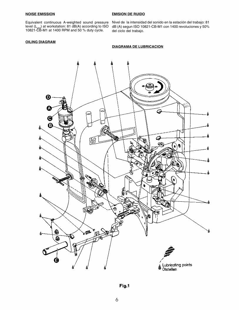
OILING DIAGRAM
EMISION DE RUIDO
Nivel de la intensidad del sonido en la estación del trabajo: 81dB (A) segun ISO 10821-CB-M1 con 1400 revoluciones y 50%del ciclo del trabajo.
DIAGRAMA DE LUBRICACION
7
LUBRICATION AND OPERATION
The machines of class 80800 have to be cleaned and lubricatedtwice a day before the morning and afternoon start on thelubricating points indicated on the oiling diagram (Fig. 1). Thesight feed oiler has to be kept filled and should be adjusted sothat it feeds two to three drops of oil per minute. The oiler has tobe refilled latest, when 2/3 of the oil is used up.For lubrication we recommend "Mobil Oil DTE Medium" orequivalent, which can be purchased from UNION SPECIALCORPORATION in 1/2 liter containers under part numberG28604L, or in 5 liter containers under part no. G28604L-5.Before operating a new machine for the first time, the needle barguard (E, Fig. 1) and the sight feed oiler, which come with theaccessories of the machine, have to be screwed in. The sightfeed oiler has to be adjusted. All lubricating points, indicated onthe oiling diagram (Fig. 1), have to be oiled.For adjusting fill the sight feed oiler half-way with oil and turn themetering pin (A, Fig. 1) a little bit out and then turn it in, untilthere will flow approx. two drops of oil per minute. This can bechecked on the sight glass (B, Fig. 1). Secure the setting of themetering pin with lock nut (C, Fig. 1). Fill the oiler.Repeat the oiling of a new machine after 10 minutes of operation!When the machine is out of operation, the oil flow can be stoppedby tilting the lever (D, Fig. 1) on the sight feed oiler.IMPORTANT! The oil flow has to be switched on again beforeoperating the machine.
NEEDLES
Each needle has both a type and size number. The type numberdenotes the kind of shank, point, length, groove, finish and otherdetails. The size number, stamped on the needle shank, denoteslargest diameter of blade, measured in hundredths of a millimeterrespectively in thousandths of an inch, midway between shankand eye. Collectively, type and size number represent thecomplete symbol, which is given on the label of all needlespackaged and sold by UNION SPECIAL.
The standard needle for machines covered in this manual is9848G250/100.For closing bags made of plastic or woven polypropylene tapesit is recommended to use needle type 9856T with teflon coating.Below are the descriptions and available sizes:
Type No. Description and sizes9848G Round shank, square point, double groove,
spotted, chromium plated.Sizes available: 150/060, 170/067, 200/080,
250/100, 300/120, 400/156.
9856T Round shank, round point, double groove,spotted, teflon-coated.Sizes available: 200/080, 250/100.
Selection of proper needle size is determined by size of threadused. Thread should pass freely through needle eye in order toproduce a good stitch formation.
To have needle orders promptly and accurately filled, an emptypackage, a sample needle or type and size number should beforwarded. Use description on label. A complete order would read:"100 needles, Type 9848G, Size 250/100".
THREADING
Thread machine as illustrated in Fig. 2.
When threading the looper, be sure the thread goes through thefront eyelets, over the take-up and through the back eyelet beforethreading the looper.
LUBRICACION Y OPERACIÓN
Las maquinas de la clase 80800 tienen que ser limpiadas ylubricadas dos veces al día antes del turno de la mañana y de latarde en los puntos de lubricación indicados en el diagrama delubricación (Fig. 1). El deposito del aceite hay que mantener lleno ydebe estar ajustado para que suelte dos a tres gotas de aceite porminuto. El deposito de aceite debe ser rellenado cuando 2/3 delaceite fue gastado.Para la lubricación recomendamos „Mobil Oil DTE Medium“ o suequivalente, que puede ser adquirido de UNION SPECIALCORPORATION en envases de ½ litro bajo el P/P No. G28604L, oen envases de 5 litros bajo el P/P No. G28604L-5.Antes de operar la maquina por la primera vez, el protector de labarra de la aguja (E, Fig. 1) y el deposito del aceite, que están enlos accesorios de la maquina, tienen que ser fijados en la maquina.El deposito de aceite tiene que ser ajustado. Todos los puntos delubricación, indicados en el diagrama de lubricación (Fig. 1) hayque lubricarlos.Para el ajuste llene el deposito hasta la mitad con aceite y ajuste elpasador de medición (A, Fig. 1) hasta que salgan aprox. dos gotasde aceite por minuto. Esto puede ser revisado en el visor (B, Fig.1). Asegure la posición del pasador de medición con la tuerca (C,Fig. 1). Llene el deposito con aceite.Repita la lubricación de una nueva maquina después de 10 minutosde operación!.Cuando la maquina no esta operando, se para el flujo del aceitedoblando la palanca (D, Fig. 1) del deposito.IMPORTANTE: Acuérdese de activar el flujo del aceite otra vez antesde arrancar la maquina.
AGUJAS
Cada aguja tiene un numero del tipo y del grosor. El numero deltipo determina el cabo, la punta, el largo, la ranura, la determinacióny otros detalles. El numero del grosor, troquelado en el cabo de laaguja, significa el diámetro máximo de la aguja, expresado encentésimos de un milímetro o milésimos de pulgada, entre el caboy el ojo de la aguja. En conjunto los números del tipo y del grosorrepresentan el símbolo completo, que aparece en la etiqueta de losempaques de las agujas, que vende UNION SPECIAL.La aguja común para las maquinas de este manual es la 9848G250/100.Para cerrar sacos de plástico o polipropileno tejido se recomiendael uso de la aguja tipo 9856T con recubrimiento de teflon.A continuación encuentra la descripción y los grosores disponib-les::
Tipo numero: Descripción y grosores9848G Cabo redondo, punta cortante, doble ranura,
cromado.Grosores disponibles: 150/060, 170/067, 200/080,
250/100, 300/120, 400/156.
9856T Cabo Redondo, punta redonda, doble ranura,recubrimiento de teflon.Grosores disponibles: 200/080, 250/100.
La selección de la aguja apropiada esta determinada por el grosordel hilo utilizado. El hilo debería pasar libremente por el ojo de laaguja, para permitir una buena formación de la puntada.
Para asegurar que los pedidos de las agujas se cumplan rápido ycorrectamente, se recomienda enviar un empaque vacío, unamuestra de una aguja o indicar los números del tipo o del grosor.Un pedido completo seria: „100 agujas, tipo 9848G, grosor 250/100“.
ENHEBRAR
Enhebre la maquina como se demuestra en la Fig. 2.
Cuando enhebre el looper, asegúrese que el hilo pase por los ojetesfrontales, encima del alimentador y por el ojete trasero antes depasarlo por el looper.

8
ADJUSTING AND THREADING INSTRUCTION FOR THETHREAD GUIDING PARTS
Proper adjustment of the thread guides and thread take-ups en-sures a durable seam and consequently tight closure of the bags.
Needle Thread: Basic adjustment see Adjusting Instructions. Shiftneedle thread take-up • (80865 MX) on support ‚(80865PX) aswell as needle thread guide ƒ (80858AX) on the machine hous-ing for proper control of the needle thread. The above mentionedparts should be adjusted so that the needle thread, when slungaround the looper blade, is controlled before the needle entersthe thread triangle.
Looper Thread: Shift looper thread guide „ (80858BX2) so, thatdepending on the stitch length a sufficient amount of looper threadis available for setting the next stitch.
Important Note: The above needle thread take-ups cannot beused on machines with long needle bar connection (e.g. 80659or 29774D) which should be exchanged against the short needlebar connection 80659B together with thread guide G334. Thethreaded hole required for mounting bracket 80865QX of needlethread take up support 80865PX will already be provided in allfuture machines.
AJUSTE E INSTRUCCIONES PARA LOS GUIA HILOS
El ajuste correcto de los guía hilos y de los alimentadores asegurauna costura duradera y por consiguiente un firme cierre de lossacos.
Hilo de la aguja: Vea el ajuste básico en Instrucciones deajustes.Mueva el alimentador del hilo de la aguja (1) (80865MX) en susoporte (2) (80865PX) igual como el guía hilo (3) (80858AX) enla carcasa para el control apropiado para el hilo de la aguja. Laspiezas antes mencionadas deberían ser ajustadas en tal manerapara que el lazo del hilo de la aguja que se forma alrededor dellooper este controlado antes de que la aguja entre en el triángulo.
Hilo del looper: Mueva el guía hilo del looper (4) (80858BX2) ental manera que dependiendo del largo de la puntada hayasuficiente hilo para la próxima puntada.
Nota Importante: Los alimentadores de hilo arriba mencionadosno se pueden utilizar en maquinas con una conexión larga de labarra de la aguja (por ejemplo 80669 o 22774D) las cualesdeberían ser cambiadas por una conexión corta 80669B enconjunto con un guía hilo G334. El hueco con rosca requeridopara el soporte de montaje 80865QX del soporte del alimentador80865PX se encontrara en todas las futuras maquinas.
THREADING THE MACHINE EHEBRAR LA MAQUINA

9
ADJUSTING INSTRUCTIONS
NOTE: Instructions stating direction or location, such as right,left, front or rear of machine, are given relative tomechanic's position in front of the machine, when themachine is placed on an adjusting table, with the pulley tothe right and the needle bar in vertical position. The pulleyrotates clockwise, in operating direction; when viewed fromthe right end of the machine.
INSERTING THE NEEDLE
Before adjusting the machine, insert a new needle with the shankas far as possible into the needle bar. The long needle groovemust point to the front (toward the operator). Tighten the needleclamp nut securely. Use the single ended open jaw wrench partNo. 21388 from the accessories of the machine.
SETTING THE LOOPER
Remove the presser foot, throat plate and feed dog and on styles80800H and HA also the needle guard for convenient access tothe machine. On styles 80800C, D and E loosen the screw (A,Fig. 3) in the feed bar (B) and push the feed bar needle guard (C)to the rear to avoid its contacting the needle (D).
For the two thread double locked stitch styles 80800C, E, H andHA, set the looper connecting rod (E) so the distance (X, Fig. 4)between the center lines of the two ball joints is 69.8 mm (2 3/4").The dimension (X, Fig. 4) should be 68.3 mm ( 2 11/16) on thesingle thread chain stitch style 80800D. For adjustment loosenthe two nuts (F, Fig. 3) and turn connecting rod (E) forward orbackward as required to obtain specified dimension, retighten nuts(F).NOTE: The left nut has a left hand thread.Set the looper (G) so the distance from the centerl ine of the needle(D) to the looper (G) is 8 mm (5/16") when the looper is at itsfarthest position to the right. Looper gauge No. 21225-5/16 canbe used advantageously in making this adjustment. For adjustmentloosen screws (H) in the looper drive lever (J), reposition as requiredto obtain specified dimension and retighten screws (H) assuringthat all end play is taken out of the looper drive lever rocker shaft.Check to insure a clearance of approx. 1 mm (.040") between thepoint of the looper and the bed end cover when the looper is at itsextreme left position. Should the looper strike the bed end cover,recheck the distance between center lines of ball joints and thelooper gauge distance as described above.
Rotate the machine pulley in operating direction so that the loopermoves from right to left. The looper point should pass as close aspossible to the back of the needle without contacting 0.08 to 0.13mm (.003 to .005") clearance. For adjustment loosen screws (A,Fig. 4) in the looper eccentric fork (B) and turn looper rocker shaft(C) on the looper rocker forward or backward as required. Retightenscrew (A).
INSTRUCCIONES DEL AJUSTE
NOTA: Todas las indicaciones como derecho, izquierdo, adelante oatrás, se refieren a la posición del mecánico en frente de lamaquina, con la maquina puesta en una mesa de trabajo,con el volante a la derecha y la barra de la aguja en posiciónvertical. El volante gira en sentido de reloj para la operación,desde el punto de vista del lado derecho de la maquina.
INSERTAR LA AGUJA
Antes de ajustar la maquina debe insertar una nueva aguja con elcabo de la aguja en la barra de la aguja. Las ranuras de las agujasdeben estar hacia adelante (hacia el operador). Apriéte la tuercaque fija la aguja firmemente. Utilíze la llave P/P No. 21388 de losaccesorios de la maquina.
AJUSTE DEL LOOPER
Quite el pie prensa tela, la placa de la aguja y el diente de arrastrey en las maquinas 80800H y HA también el guarda aguja para tenermejor acceso a la maquina. En los estilos 80800C, D y E suelte eltornillo (A, Fig.3) en la barra de alimentación B y mueva el guardaaguja (C) en la barra de alimentación hacia atrás para evitar quetenga contacto con la aguja (D).
Para las maquinas de dos hilos como 80800C, E, H y HA ajuste labarra del looper (E) para que la distancia (X, Fig. 4) entre los centrosde las junturas tenga una distancia de 69,8 mm (2 3/4"). Estadistancia (X, Fig. 4) debería ser 68,3 mm (2 11/16) en las maquinasde un solo hilo 80800D. Para ajustarlo suelte las dos tuercas (F,Fig. 3) y gire la barra (E) hacia adelante o hacia atrás para conseguirla distancia requerida. Apriete nuevamente las tuercas (F).
NOTA: La tuerca izquierda tiene una rosca izquierda.Ponga el looper (G) de manera tal que la distancia entre el medio dela aguja (D) al looper (G) sea de 8 mm (5/16) cuando el looper seencuentre en su posición a la extrema derecha. El calibrador P/PNo. 21225-5/16 puede ser utilizado para un ajuste preliminar. Paraajustar suelte los tornillos (H) en la palanca (J) del looper, mueva lapalanca para obtener la distancia requerida y apriete los tornillos(H), asegurando que la barra del accionamiento del looper no tengajuego. Asegure que haya una distancia de aprox. 1 mm (.040") entrela punta del looper y la tapa final de la maquina cuando el looper seencuentre en su posición de la extrema izquierda. Si el looper tocaríala tapa, revise otra vez la distancia entre los centros de las junturasy la distancia entre el looper y la aguja como se ha descritoanteriormente.
Gire el volante en sentido de operación para que el looper se muevadesde la derecha hacia la izquierda. La punta del looper deberíapasar muy cerca detrás de la aguja sin tocarla – distancia 0.08 a0,13 mm (.003 a .005"). Para lograr este ajuste debería soltar eltornillo (A, Fig. 4) en la horquilla excéntrica (B) del looper y girar eleje del looper (C) hacia adelante o hacia atrás. Apriete el tornillo (A)otra vez.
Fig. 3

10
SETTING HEIGHT OF NEEDLE BAR
Remove the face cover on machine arm. Rotatemachine pulley in operating direction until thelooper point, moving to the left, projects 1 to 1.5mm (.040" to .060") left of the needle (see Fig. 5).Lower edge of looper and upper edge of needleeye must be flush in this position. If adjustment isnecessary, loosen clamp screw (A, Fig. 6) in theneedle bar connection and move the needle barup or down, as required. Retighten screw (A) andremount face cover.
SETTING THE FEED DOG
At highest point of feed dog travel, the feed dog(B, Fig. 6) should be set so, that the rear teethproject their full depth above the throat platesurface. For setting remove the feed dog andadjust the supporting screw (K, Fig. 3) on the topof the feed bar to the required height. Remountthe feed dog, and on styles 80800H and HA alsothe needle guard.
After loosening screws (A, Fig. 7) rear in the feedrocker (B), the feed bar with feed dog can bemoved laterally to center the feed dog in the throatplate slots, if required. Retighten screws (A).
CHANGING STITCH LENGTH
On styles 80800C, D and E stud (C, Fig. 6) forchainging the stitch length is accessible from theoutside. On styles 80800H and HA the housingfor the tape cutter and the rear cloth plate have tobe removed for changing the stitch length.
NOTE: Any change in stitch length will necessitate acorresponding change in the needle guardsetting!
SETTING THE NEEDLE GUARD
The needle guard (C, Fig. 3) has to be set so, that it just contacts theneedle at its most forward point of travel, without deflecting it.On styles 80800C, D and E loosen screw (A, Fig. 3) in the feed bar(B) and adjust the needle guard (C) accordingly. Retighten screw(A).On styles 80800H and HA loosen the feed dog fastening screw andmove the needle guard accordingly. Retighten screw and make surethat the feed dog rests on the supporting screw in the feed bar.
AJUSTE DE LA BARRA DE LA AGUJA
Remueva la tapa frontal en el brazo de la maquina. Gireel volante de la maquina en sentido de operación hastaque la punta del looper pase 1 a 1,5 mm (.040" a .060")la aguja (vea Fig. 5). En esta posición el borde inferiordel looper tiene que encontrarse en el limite superior delojo de la aguja. Si se requiere ajuste, suelte el tornillo (A,Fig. 6) en la conexión de la barra de la aguja y mueva labarra hacia arriba o hacia abajo como requerido. Aprieteel tornillo (A) y ponga la tapa frontal otra vez.
AJUSTE DEL ALIMENTADOR
En el punto mas alto del recorrido del alimentador, losdientes del alimentador (B, Fig. 6) deberíansobrepasar la placa de la aguja por la altura completade los dientes. Para lograr este ajuste remueva elalimentador y ajuste el tornillo de soporte (K, Fig. 3)en la parte superior de la barra de la alimentación a laaltura requerida. Monte el alimentador otra vez y enlos estilos 80800H y HA también el guarda aguja.
Después de haber soltado los tornillos (A, Fig. 7) en elmarco del transporte (B), la barra de alimentación conel alimentador puede ser movido lateralmente paracentrar el alimentador en las ranuras de la placa de laaguja, si haga falta. Apriete los tornillos (A).
AJUSTE DEL LARGO DE LA PUNTADA
En los estilos 80800C, D y E el perno (C Fig. 6) paracambiar el largo de la puntada se accesa desde afuera.En los estilos 80800H y HA se deben remover lachumacera para el cortador de cinta y la plancha decostura trasera para cambiar el largo de la puntada.Remueva la tapa trasera.
NOTA: Después de cada cambio en el largo de la puntada, se debeajustar el guarda aguja!
AJUSTE DEL GUARDA AGUJA
Hay que ajustar el guarda aguja (C, Fig. 3) para que toque en sumovimiento hacia delante la aguja pero no la desvíe.En los estilos 80800C, D y E suelte el tornillo (A, Fig. 3) en el soportedel transportador (B) y ajuste el guarda aguja (C). Apriete el tornillo(A) nuevamente.En los estilos 80800H y HA suelte el tornillo que fija el alimentadory mueva el guarda aguja. Apriete el tornillo otra vez y asegúreseque el alimentador reposa en el tornillo de soporte de la barra de laalimentación.
The length of the stitch can be adjusted by raising or lowering thestud (C, Fig. 6) in the segment slot of the feed rocker (D). Loweringstud (C) will lengthen the stitch. After lossening nut (E), stud (C) canbe moved accordingly. When the desired stitch lenght is obtained,retighten nut (E).Remount housing for cutter and rear cloth plate on styles 80800Hand HA.
El largo de la puntada se ajusta moviendo el perno (C, Fig. 6) en laranura del eje oscilante (D). Bajando el perno (C) pone la puntadamas larga y subiéndolo la pone mas corta. Después de aflojar latuerca (E), el perno (C) se deja mover. Cuando se logra el largo dela puntada deseado, hay que apretar la tuerca (E) otra vez .Vuelva a montar la chumacera para el cortador de cinta y la planchade costura en los estilos 80800H y HA.

11
MOUNTING AND SETTING THE PRESSER FOOT
Remove the needle and rotate the pulley until the feed dog isbelow the throat plate. Depress the presser foot lifter leverand insert the presser foot in the two presser bars (L and R,Fig. 8). The right presser bar (R) should only engage with itspivot in the groove of the presser foot shank.
Loosen the two lock nuts (A, Fig. 8) and align with the two setscrews (B), the needle slot in the presser foot with the needleslot in the throat plate. Secure this setting with the two locknuts (A). Note: The two set screws (A) should just contact thepivot of the right presser bar (R) but not be tightened. Nowtighten the two set screws left in the presser foot shank onthe left presser bar. Insert the needle.
AJUSTE DEL PIE PRENSA TELA
Remueva la aguja y gire el volante hasta que el alimentador seencuentre debajo de la placa de la aguja. Apriete la palanca levantadoradel pie e inserte el pie en las barras (L y R, Fig. 8). La barra derecha(R) debería entrar solamente con el pivote en la apertura del pie.
Afloje las dos tuercas (A, Fig. 8) y alinee con los dos tornillos (B) laranura para la aguja en el pie con la ranura para la aguja en la placa dela aguja. Asegure este ajuste con los dos tornillos (A). Nota: Los dostornillos (A) deberían tocar solamente el pivote de la barra de presiónderecha (R) pero no apretarla. Ahora apriete los dos tornillos al ladoizquierdo del tronco del pie de la barra de presión izquierda. Inserte laaguja otra vez.
PRESSER FOOT PRESSURE
Rotate the pulley until the feed dog isbelow the throat plate. Remove the facecover left on machine arm and turn outthe T-screw (H, Fig. 10) on the top ofthe machine arm, until it does not excertany pressure on the leaf springs. In thisposition, the pressure excerted on thepresser foot, should be just strongenough to keep it flat on the throat plate.By relocating the collars (A, Fig. 9),which serve as a leaf spring rest, on theleft and right presser bar, the pressurecan be changed. Raising the collarsincreases the pressure, lowering thecollars decreases the pressure.
Set the presser bar lifter collar (B, Fig.9) on the left presser bar so, that thereis a distance of apporx. 1.5 mm (1/16in.) betweeen lifter lever stud (C) andlower surface of the lifter collar (B), whenthe presser foot rests on the throat plate(see Fig. 9). Set the collar (D) on theright presser bar close to the fork of thepresser bar lifter collar (B) on the leftpresser bar.The presser foot lift is limited with theupper stop collar (E, Fig. 9) on the leftpresser bar. When the needle is in itslowest position and the presser foot islifted with presser foot bottom tilted up,the needle bar respectively needleclamp nut should not contact the presserfoot bottom. Set collar (E) accordingly.
AJUSTE DE LA PRESION DEL PIE
Gire el volante hasta que los dientes deltransportador se encuentren debajo de la placade la aguja. Remueva la tapa frontal en el brazoy afloje el tornillo (H, Fig.10) en la partesuperior de la maquina hasta que no haya maspresión en las ballestas. En esta posición lapresión al pie es solamente para mantenerloplano en la placa de la aguja. Moviendo losanillos (A, Fig. 9), que sirven como soportepara las ballestas, en la barra de presiónizquierda y derecha, se puede modificar lapresión. Subiendo los anillos aumenta lapresión, bajando los anillos disminuye lapresión.
Coloque el anillo (B, Fig. 9) para levantar labarra de presión en la barra izquierda en talmanera para que haya una distancia de aprox.1.5 mm (1/16") entre el perno levantador (C) yla superficie inferior del anillo (B), cuando elpie reposa en la placa de aguja (vea Fig. 11).Coloque el anillo (D) en la barra derecha cercaa la horquilla del anillo (C) para levantar la barrade presión de la barra izquierda.
La altura del levantamiento del pie esta limitadopor el anillo de parada (E, Fig. 9) en la barrade presión izquierda. Cuando la aguja este ensu posición mas baja y el pie este levantado einclinado hacia arriba, la barra de la aguja o latuerca que fija la guía no deberían tocar la parteinferior del pie. Coloque el anil lo (E)adecuadamente.
Ahora ajuste el tornillo con forma de „T“ (H,Fig. 10), para conseguir la presión necesariapara una alimentación optima (determine estocon pruebas de costura). Asegure este ajustecon la tuerca (J), que al mismo tiempo fija latapa superior del brazo. Coloque otra vez latapa frontal.
TENSION DEL HILO
El tensor (A, Fig. 10) del hilo de la agujadebería ser ajustado de tal manera que latensión del hilo de la aguja produzca unaspuntadas uniformes. En los estilos con costurade doble cadeneta de dos hilos, el tensor (B)debe ser ajustado apenas lo suficiente paramantener la costura.
Now turn in T-screw (H, Fig. 10) until the necessary presserfoot pressure for proper feeding is excerted (determine wirsewing tests). Secure this setting with the knurled nut (J), whichsimultaneously fastens the upper arm cover. Remount the facecover.
THREAD TENSION
The tension (A, Fig. 10) on the needle thread should be fairlystrong to produce uniform stitches. On the two thread doublelocked stitch styles the tension (B) on the looper thread shouldbe barely sufficient to steady it.

12
LOOPER THREAD TAKE-UP
On the two thread double locked stitch styles, the height ofthe looper thread take-up (A, Fig. 11) is set so, that the cast-off hook (C) forces the looper thread over the corner (B) ofthe looper thread take-up (A) at the time the point of thedescending needle is flush with the lower edge at looper orprojects up to 1 mm (.040") below the lower edge of looper.Draw the looper thread into the machine, rotate pulley inoperating direction and note the position of the needle pointto lower edge of looper at the time the cast-off (C) forces thelooper thread over the corner (B).
For setting the looper thread take-up loosen screw (D, Fig.11).When needle point is positioned above the lower edge oflooper, the looper thread take-up (A) has to be raisedaccordingly. When the needle point is positioned more than1 mm (.040") below the lower edge of looper, the looper threadtake-up (A) has to be lowered accordingly. Retighten screw(D).
SETTING NEEDLE THREAD TAKE-UP ROLLER ANDEYELET
On the two thread double locked stitch styles 80800C, E, Hand HA, the height of the needle thread take-up roller (C,Fig. 10) is set so that the needle thread on the downstroke ofthe needle just contacts the roll at the time the needle threadloop is released from the looper. Loosen screw (D) and setthe needle thread take-up roller accordingly. Retighten screw(D).
On the single thread chain stitch style 80800D the needlethread take-up roller (C) should be positioned so as not tocontact the needle thread at any time.
On all styles the eyelet (E, Fig. 10) should be positioned so,that the needle thread runs nearly horizontal, parallel to clothplate, between eyelet (G) on needle bar connection and eyelet(E) on machine arm, when the needle is in its upmost position.Eyelet (E) is secured by screw (F).
ALIMENTACION DEL HILO DEL LOOPER
En las maquinas de costura de doble cadeneta de dos hilos, seajusta la altura del alimentador del hilo del looper (A, Fig. 11) en talmanera que el gancho (C) del alimentador del hilo del looper suelteel hilo sobre el canto (B) del alimentador (A) en el momento cuandola punta de la aguja coincida con el borde inferior del looper o pasehasta 1 mm (.040") debajo el borde inferior del borde del looper.Enhebre el hilo del looper, gire el volante en sentido de operacióny memorice la posición de la punta de la aguja referente al looperen el momento cuando el gancho del alimentador (C) suelte el hilosobre el canto (B).
Para ajustar el alimentador del hilo del looper suelte el tornillo (D,Fig. 11). Si la punta de la aguja se encuentra por encima delborde inferior del looper, hay que ajustar el alimentador (A) haciaarriba. Si la punta de la aguja se encuentra más que 1 mm pordebajo del borde inferior del looper, hay que bajar el alimentador(A) adecuadamente. Apriete el tornillo (D) otra vez.
ALIMENTACION DEL HILO DE LA AGUJA
En las maquinas de costura de doble cadeneta 80800C, E y HA, laaltura del rodillo (C, Fig. 10) del alimentador del hilo de la agujaesta fijado de manera tal, que el hilo durante el movimiento de laaguja hacia abajo solamente toque el rodillo en el mismo momentocuando el looper suelte el lazo del hilo de la aguja. Suelte el tornillo(D) y ajuste el rodillo del alimentador del hilo de la agujaadecuadamente. Apriete el tornillo (D) otra vez.
En las maquinas de cadeneta simple 80800D el rodillo (C) delalimentador del hilo de la aguja debe ser colocado de forma quenunca toque el hilo.
En todos los estilos el ojete (E, Fig. 10) debería ser puesto paraque el hilo de la aguja se mueva casi en forma horizontal,paralelamente a la tapa principal de la maquina, entre el ojete (G)en la conexión de la barra de la aguja y el ojete (E) en el brazo dela maquina, cuando la aguja se encuentre en su posición mas alta.Asegure el ojete (E) con el tornillo (F).

13
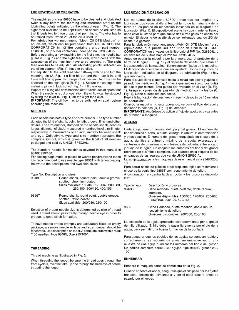
AJUSTE DEL CORTADOR DE CADENETA EN LOS ESTILOS 80800C,D Y E
Ajuste la cuchilla fija (A, Fig. 12) de tal manera que la punta quede alras con la plancha de aguja .Ajuste la cuchilla móvil en el soporte de la cuchilla, de forma que elcanto de corte se mueva libremente con una holgura de 0,3 a 0,5mm por debajo de la plancha de aguja y que se monte sobre la cuchillafija 0,5 rnm en el momento del corte.
INSTRUCCIONES DE AJUSTE PARA EL CORTADOR DE CINTA ENLOS ESTILOS 80800H Y HA
1. Para quitar el protector del cortador, gire la polea de la maquina endirección de trabajo (sentido de las agujas del reloj) hasta que laaguja llegue a la posición mas alta de su recorrido, retire la planchade aguja de la posición de trabajo y remueva los 2 tornillos quesujetan el protector del cortador. Remueva el protector, la planchade tela, la lengüeta de accionamiento, el pie prensatelas, la planchade aguja, los dientes alimentadores y el guarda agujas en el ordenindicado para que sea más fácil su acceso.
Las llaves fijas 116 y 21388C deben usarse para un mejor ajustede los tornillos en el mecanismo cortador de cinta.
2. Deje la plancha de aguja momentaneamente en su sitio. Sueltelos tornillos de cabeza hexagonal (D, Fig. 13) y ajustelos de maneraque la distancia entre la superficie superior de la plancha de agujay el centro del hueco del pasahilo que asegura la lengüeta sea de22,5 mm (Ver Fig. 15). Vuelva a ajustar el tornillo (D, Fig. 13) conla arandela de seguridad.
3. Ajsute la cuchilla inferior (A, Fig. 13) de manera que el borde decorte quede al ras con la parte superior de la plancha de aguja (B)y ajuste en su posición el tornillo de cabeza hexagonal (C).Monte de nuevo el guarda agujas, el diente de alimentación y laplancha de aguja.
4. Vuelva a montar la lengüeta de accionamiento (K, Fig. 14) y ajustelade manera tal que quede al ras con la parte superior de la planchade aguja.
5. Con un destornillador, empuje el resorte inserto en el soporte de lacuchilla (Y, Fig. 14) hacia atrás e inserte la cuchilla superior (L) enel soporte de la cuchilla superior (M). Suba la cuchilla superiorhasta su punto mas alto, hasta que la parte posterior del borde lacuchilla pare en el sujetador de la cuchilla. Asegure el tornillosujetador (N) ligeramente.
6. Suelte el tornillo (P, Fig. 15) y mueva la lengüeta (Q) a la extremaizquierda. Gire el volante hasta que el diente de encaje (E, Fig. 13)llegue a su posición mas baja. Gire el tornillo (F) hasta que el bordedel reten (G) se cierre sobre el borde del diente de encaje (E).Agregue 1/4 a 1/2 vuelta al tornillo (F) para asegurarlo encondiciones de operación. Asegure nuevamente la arandela deseguridad sobre el tornillo (F). Si el tornillo (F) se aprieta demasiado,el mecanismo no funcionará. Pequeñas diferencias pueden serajustadas soltando un poco los tornillos (Z) y ajustando el dientede encaje (E). Reasegure de nuevo los tornillos (Z) firmemente.
Si no se consigue el ajuste del retenedor y el diente de encaje,puede ser necesario ajustar la varilla de conexión (H) ajustandolas arandelas de seguridad (J). La distancia correcta centro a centrode la varilla de conexión es de 103.2 mm. Se pueden utilizarajustadores individuales para corregir pequeñas diferencias deconfección en los rollos de cinta.
7. Mueva la lengüeta (Q, Fig. 15) hacia la derecha de manera que eldiente de encaje (R) descanse en la extrema derecha de lalengüeta. La lengüeta debe haber sido pulida para que eldeslizamiento sea mas suave y se asegure el accionamiento deldisparo durante la operación de la maquina.
SETTING THE THREAD CHAIN CUTTING KNIVES ONSTYLES 80800C, D AND E
Set the stationary knife (A. Fig. 12) so, that its tip is flushwith the supporting surface for the throat plate on the bedcasting.Fasten the movable knife in the knife lever so, that its tipmoves freely .012 to .020 in. (0.3 to 0.5 mm) below theunderside of the throat plate and its cutting edge overlapsthe cutting edge of the stationary knife by .040 in (0.5 mm)when in cutting position.
INSTRUCTIONS FOR TAPE CUTTER FOR STYLES80800H AND HA
1. To remove the tape cutter housing, turn the pulley inoperating direction (clockwise) until the needle is at highposition, move the cloth plate swinging extension out ofoperating position and remove the two tape cutterhousing screws. Remove the housing, cloth plate, upperknife actuating shoe, presser foot, throat plate, feed dogand needle guard in the order named for convenientaccess.
Wrenches Nos. 116 and 21388C can be usedadvantageously for adjusting the hexagonal head screwsused in the tape cutting mechanism.
2. Lay the throat plate temporarily on its seat. Loosen thehexagonal head adjusting screw (D, Fig. 13) and set sothat the distance between top surface of throat plateand the center of thread hole for fastening the actuatingshoe is 22.5 mm (7/8 in.) (see Fig. 15). Retighten screw(D, Fig. 13) with lock nut.
3. Set the lower knife (A, Fig. 13) so that the cutting edgeis even with the top of throat plate (B) and tighten it inthis position with the hexagonal head screw (C).Reassemble needle guard, feed dog and throat plate.
4. Assemble actuating shoe (K, Fig. 14) and set it so thatthe top surface of actuating shoe is even with the topsurface of throat plate.
5. With a screwdriver, press the spring loaded knife levershaft (Y, Fig. 14) to the rear and insert upper knife (L) inupper knife lever (M). Raise the upper knife as high as itwill go, until the back of the knife cutting edge stops onthe knife lever. Tighten the clamp screw (N) slightly.
6. Loosen screw (P, Fig. 15) and move shoe (Q) to extre-me left. Turn handwheel until pawl (E, Fig. 13) is at itslowest position. Turn screw (F) until the edge of ratchetblock (G) snaps over the edge of pawl (E), then add 1/4to 1/2 turn more to ensure adequate clearance underoperating conditions. Retighten the lock nut of the screw(F). If screw (F) is turned too far the mechanism will notwork. Small differences can be equalized when looseningscrews (Z) and adjusting the pawl (E) accordingly.Retighten screws (Z) firmly.
If ratchet block and pawl will not engage it may benecessary to adjust connecting rod (H) by means of locknuts (J). The correct center to center distance of theconnecting rod should be 103.2 mm (4 1/16 in.).Individual tape clippers may require slightly differentsettings due to slight accumulation of tolerances inmanufacture.
7. Move shoe (Q, Fig. 15) to the right so that pawls (R) willrest on the extreme right end of shoe. Shoe should havepolished end to the riht and point of pawls may overlapslightly over outside to insure trigger action duringoperationg of machine.
14

SETTING THE THREAD CHAIN CUTTING KNIVES ONSTYLES 80800C, D AND E (continued)
8. When acutating shoe (K, Fig. 1e) is raised slightly, tripdog (S, Fig. 15) should allow pawl (R) to slide off shoe(Q) and the cutting action is released within 1 1/2 turn orless of the handwheel.
Make sure that the knives engage for their full length.Proceed as follows:Raise actuating shoe (K, Fig. 14) slightly and turnhandwheel in operating direction until upper knife (L) is inits lowest position. Left at the tip of the knives, the cuttingedge of the upper knife should overlap the cutting edgeof the lower knife by 1 mm (.040 in.)Adjust the upper knife accordingly and snug stop screw(O) against the upper knife. Now tighten clamp screw (N)firmly.
When open there should be about 4.8 mm (3/16 in.)opening, right at the pilot of the upper knife (see Fig. 14).
NOTE: When the knives (A, Fig. 13) and L, Fig. 14) areresharpened, their adjustment is maintained by onlyraising and lowering them in their holders, according tothe stock removed while grinding.
9. The position of the tape cutter actuating shoe (K, Fig. 14)determines the length of tape extending beyond the bagat the start of closure. The extending length of tape at thefinish of closure is not adjustable.Raising the actuating shoe in its slot shortens theextending length of tape on start of closure, lowering theshoe lengthens it.
Also the trip dog operating cam (T, Fig. 15) can be retardedor advanced to vary the length of the tape at the start ofclosure. Loosen screws (U) and turn the operating cam(T) toward the handwheel end of machine to shorten thextending length of tape and in the opposite direction tolengthen it. Retighten screws (U).
The actuating shoe tension spring (V, Fig. 15) is adjustablevor various weights of material. Use screw (W) and locknut (X) to make this adjustment. The tension should bejust strong enough to press the actuating shoe down, backto its home position.
Remount cloth plate and tape cutter housing.
TAPE FOLDER FOR STYLE 80800HA
Assemble the tape folder for style 80800HA with fasteningparts as shown on page 38. The folder has to be aligned withthe support rod to the top surface of throat plate. The heightshould be adjusted so, that the tape fully covers the bagopening and the seam is located in the lower third of thetape (see Fig. 16).
INSTRUCCIONES DE AJUSTE PARA EL CORTADOR DE CINTA ENLOS ESTILOS 80800H Y HA (continuación)
8. Cuando la lengüeta de accionamiento (K, Fig. 14) está subiendosuavemente, la punta del diente (S, Fig. 15), deberá permitir queel diente de encaje (R) deslice sobre el patín (Q) y la cuchillacortará la cinta en 1 1/2 vueltas o menos del volante.Asegurese que las cuchillas están ajustadas para cortar todo elancho de cinta.Siga estas instrucciones:Eleve la lengüeta de accionamiento (K, Fig. 14) ligeramente y gireel volante en sentido de operación hasta que la cuchilla superior(L) llegue a su posición mas baja. A la izquierda de la punta de lacuchilla, el borde cortante de la cuchilla superior debe sobrepasarel borde cortante de la cuchilla inferior por 1 mm.Ajuste la cuchilla superior y acomode el tornillo tope (O) contra lacuchilla superior. A continuación apriete el tornillo de sujeción (N)firmemente.
Cuando las cuchillas esten abiertas a su maximo recorrido, deberiahaber una distancia de 4,8 mm (ver Fig. 14) justo en el soporte dela cuchilla superior.
NOTA: Cuando las cuchillas (A, Fig. 13) y (L, Fig. 14) sean afiladas,su ajuste se logra subiendo y bajandolas en sus soportes. Serecomienda sacalas para ser afiladas.
9. La posición de la lengüeta de accionamiento del cortador de cinta(K, Fig. 14) determina el largo de la cinta que sobresale en elsaco al comienzo del cierre. La cinta sobrante al final del saco noes ajustable.Subiendo la lengüeta de accionamiento en su base acorta el largode la cinta al comienzo del cierre, bajandola se acorta.
También el diente de operación del alimentador (T, Fig. 15) puedeser retrasado o adelantado para variar el largo de la cinta alcomienzo del saco. Suelete los tornillos (U) y gire el diente deoperación (T) hacia el volante al final de la maquina para acortarel largo de la cinta y en sentido contrario para alargarlo. Reasegurelos tornillos (U) nuevamete.
El muelle de accionamiento (V, Fig. 15) es ajustable para los dis-tintos gruesos del material. Este ajuste se realiza por medio deltornillo (W) y la contra tuerca (X). La tensión debe ser lo suficientepara presionar el diente de operación hacia abajo, de regreso asu posición original.
Monte de nuevo la plancha de aguja y el cojinete del cortador decinta.
DOBLADILLADOR DE CINTA PARA ESTILOS 80800HA
Ensamble el dobladillador de cinta para estilos 80800HA consujetadores, como se muestra en la página. El dobladillador debeser alineado con la varilla de soporte a la parte anterior de la planchade aguja. La altura debe ser ajustada de manera tal, que la cintacubra totalmente la boca del saco y la costura quede localizada en eltercio bajo de la cinta (ver Fig. 16).
15
The folder for style 80800HA can be adjustedfor tape widths from 50 to 63 mm (2 to 2 1/2 in.)Set the guide so that the bag opening will be boundequally.Assemble the tape reel as shown on page 38.
El dobladillador de cinta para estilos 80800HA puede serajustado para cintas de 50 a 63 mm (2 to 2 1/2 in.) deancho. Ajuste la guía de manera tal que la boca del sacoquede ajustada dentro de ella.Ensamble el rollo de cinta de acuerdo a lo mostrado en lapágina 38.
TORQUE REQUIREMENTS
Torque specifications given in this catalog are measured inNm (Newton-meter) and inch-pound (in.lbs.).All straps and eccentrics must be tightened to 2,2 - 2,4 Nm(19-21 in.lbs.), unless otherwise noted. All nuts, bolts, screwsetc., without torque specifications must be secured as tightlyas possible, unless otherwise noted. Special torquespecifications of connecting rod, links, screws etc., are shownon part illustrations.
REQUERIMIENTOS DE ESFUERZOS DE TORSIÓN (TORQUES)
Las especificaciones de los torques se indican en este catálogo en Nm(Newtonmetros) y pulgada-libra (in.lbs).Todos los cojinetes de conexión y excéntricas hay que apretarlos con2,2 – 2,4 Nm (19 – 21 in.lbs) a no ser que se indique de otra manera.Todas las tuercas, pernos, tornillos etc. sin indicaciones de torquesdeberían ser apretados lo máximo posible, si no se indica de otra manera.Especificaciones especiales de los torques para barras de conexión,junturas, tornillos etc. se encuentran en las ilustraciones.

16
ORDERING WEAR AND SPARE PARTS
ILLUSTRATIONS
This manual has been arranged to simplify ordering wear andspare parts. Exploded views of various sections of the mechanismare shown so that the parts may be seen in their actual positionin the sewing machine. On the page opposite the illustration willbe found a listing of the parts with their part numbers, descriptionsand the number of pieces required in the particular view beingshown.
Numbers in the first column are reference numbers only andmerely indicate the position of that part in the illustration.Reference numbers should never be used in ordering parts.Always use the part number listed in the second column.
Component parts of sub-assemblies which can be furnished forrepairs are indicated by indenting their description under thedescription of the main sub-assembly.
At the back of the catalog will be found a numerical index of allparts shown in this catalog. This will facilitate locating theillustration and description when only the part number is known.
IMPORTANT! ON ALL ORDERS, PLEASE INCLUDE PARTNUMBER, PART NAME AND STYLE OF MACHINE FOR WHICHPART IS ORDERED.
PEDIDO DE PIEZAS DE REPUESTO
ILUSTRACIONES
Este catálogo fue diseñado para facilitar los pedidos de los repuestos.Los dibujos de grupos específicos del mecanismo demuestran laposición de las piezas en la máquina de coser. En la página en frentede la página de la ilustración se encuentra un listado de las piezas consu número de repuesto, descripción y la cantidad requerida para lasección indicada.
Los números de la primera columna son números de referencia eindican donde se encuentra la piezas en la ilustración. Los númerosde referencia no se deben utilizar en sus pedidos de repuestos. Utilicesiempre el número de repuesto de la segunda columna.
Componentes de piezas compuestas que se pueden suministrar comorepuestos se encuentran diferenciadas de tal forma que lasdescripciones están desplazadas hacia la derecha referente a ladescripción de la pieza compuesta.
Al final del catalogo se encuentran todas las piezas enseñadas eneste catalogo en orden numérico. Esto facilita la ubicación de lailustración y descripción cuando se conozca solamente el numero dela pieza.
IMPORTANTE! EN TODAS LAS ORDENES INCLUYA POR FAVOREL NUMERO Y LA DESCIPCION DE LA PIEZA Y EL ESTILO DEMAQUINA PARA CUAL SE ORDENA LA PIEZA.

17
EXPLODED VIEWS
AND
DESCRIPTION OF PARTS
VISTAS Y DESCRIPCION
DE LAS
PARTES Y PIEZAS
18
19
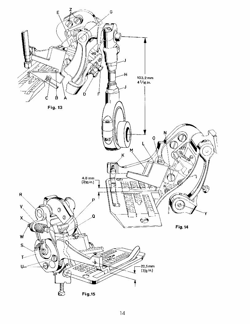
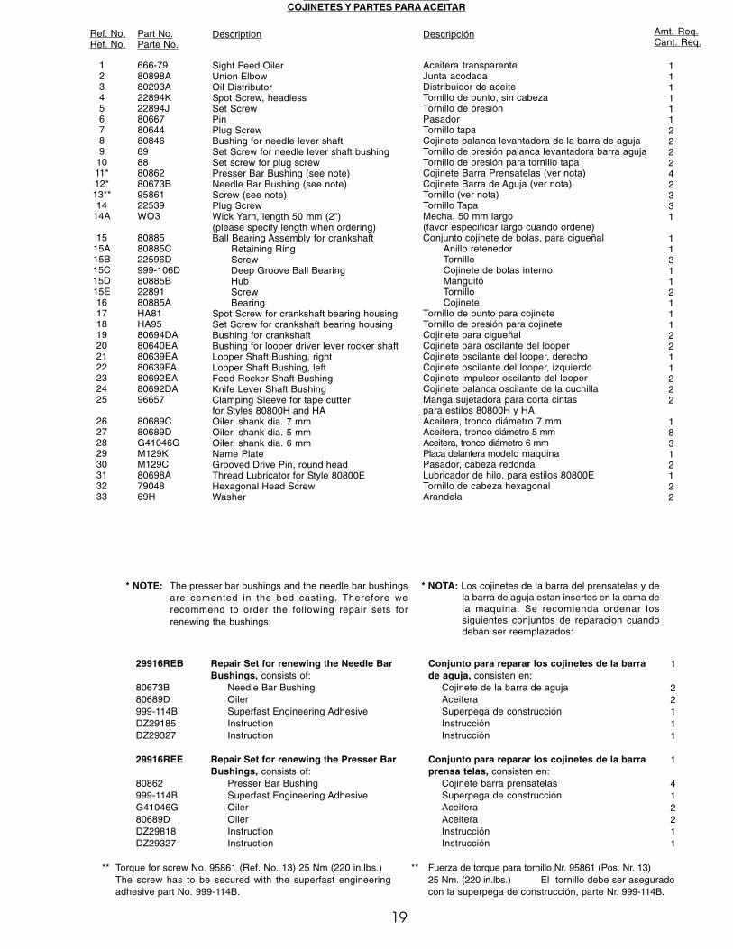
US GS O G SCOJINETES Y PARTES PARA ACEITAR
Ref. No.Ref. No.
Part No.Parte No.
Description Descripción Amt. Req.Cant. Req.
123456789
1011*12*13**14
14A
1515A15B15C15D15E16171819202122232425
2627282930313233
666-7980898A80293A22894K22894J80667806448084689888086280673B9586122539WO3
8088580885C22596D999-106D80885B2289180885AHA81HA9580694DA80640EA80639EA80639FA80692EA80692DA96657
80689C80689DG41046GM129KM129C80698A7904869H
Sight Feed OilerUnion ElbowOil DistributorSpot Screw, headlessSet ScrewPinPlug ScrewBushing for needle lever shaftSet Screw for needle lever shaft bushingSet screw for plug screwPresser Bar Bushing (see note)Needle Bar Bushing (see note)Screw (see note)Plug ScrewWick Yarn, length 50 mm (2")(please specify length when ordering)Ball Bearing Assembly for crankshaft
Retaining RingScrewDeep Groove Ball BearingHubScrewBearing
Spot Screw for crankshaft bearing housingSet Screw for crankshaft bearing housingBushing for crankshaftBushing for looper driver lever rocker shaftLooper Shaft Bushing, rightLooper Shaft Bushing, leftFeed Rocker Shaft BushingKnife Lever Shaft BushingClamping Sleeve for tape cutterfor Styles 80800H and HAOiler, shank dia. 7 mmOiler, shank dia. 5 mmOiler, shank dia. 6 mmName PlateGrooved Drive Pin, round headThread Lubricator for Style 80800EHexagonal Head ScrewWasher
Aceitera transparenteJunta acodadaDistribuidor de aceiteTornillo de punto, sin cabezaTornillo de presiónPasadorTornillo tapaCojinete palanca levantadora de la barra de agujaTornillo de presión palanca levantadora barra agujaTornillo de presión para tornillo tapaCojinete Barra Prensatelas (ver nota)Cojinete Barra de Aguja (ver nota)Tornillo (ver nota)Tornillo TapaMecha, 50 mm largo(favor especificar largo cuando ordene)Conjunto cojinete de bolas, para cigueñal
Anillo retenedorTornilloCojinete de bolas internoManguitoTornilloCojinete
Tornillo de punto para cojineteTornillo de presión para cojineteCojinete para cigueñalCojinete para oscilante del looperCojinete oscilante del looper, derechoCojinete oscilante del looper, izquierdoCojinete impulsor oscilante del looperCojinete palanca oscilante de la cuchillaManga sujetadora para corta cintaspara estilos 80800H y HAAceitera, tronco diámetro 7 mmAceitera, tronco diámetro 5 mmAceitera, tronco diámetro 6 mmPlaca delantera modelo maquinaPasador, cabeza redondaLubricador de hilo, para estilos 80800ETornillo de cabeza hexagonalArandela
111111222242331
1131121112211222
18312122
* NOTE: The presser bar bushings and the needle bar bushingsare cemented in the bed casting. Therefore werecommend to order the following repair sets forrenewing the bushings:
* NOTA: Los cojinetes de la barra del prensatelas y dela barra de aguja estan insertos en la cama dela maquina. Se recomienda ordenar lossiguientes conjuntos de reparacion cuandodeban ser reemplazados:
29916REB
80673B80689D999-114BDZ29185DZ29327
29916REE
80862999-114BG41046G80689DDZ29818DZ29327
Repair Set for renewing the Needle BarBushings, consists of:
Needle Bar BushingOilerSuperfast Engineering AdhesiveInstructionInstruction
Repair Set for renewing the Presser BarBushings, consists of:
Presser Bar BushingSuperfast Engineering AdhesiveOilerOilerInstructionInstruction
Conjunto para reparar los cojinetes de la barrade aguja, consisten en:
Cojinete de la barra de agujaAceiteraSuperpega de construcciónInstrucciónInstrucción
Conjunto para reparar los cojinetes de la barraprensa telas, consisten en:
Cojinete barra prensatelasSuperpega de construcciónAceiteraAceiteraInstrucciónInstrucción
1
22111
1
412211
** Torque for screw No. 95861 (Ref. No. 13) 25 Nm (220 in.lbs.)The screw has to be secured with the superfast engineeringadhesive part No. 999-114B.
** Fuerza de torque para tornillo Nr. 95861 (Pos. Nr. 13)25 Nm. (220 in.lbs.) El tornillo debe ser aseguradocon la superpega de construcción, parte Nr. 999-114B.

20
21
Ref. No.Ref. No.
Part No.Parte No.
Description Descripción Amt. Req.Cant. Req.
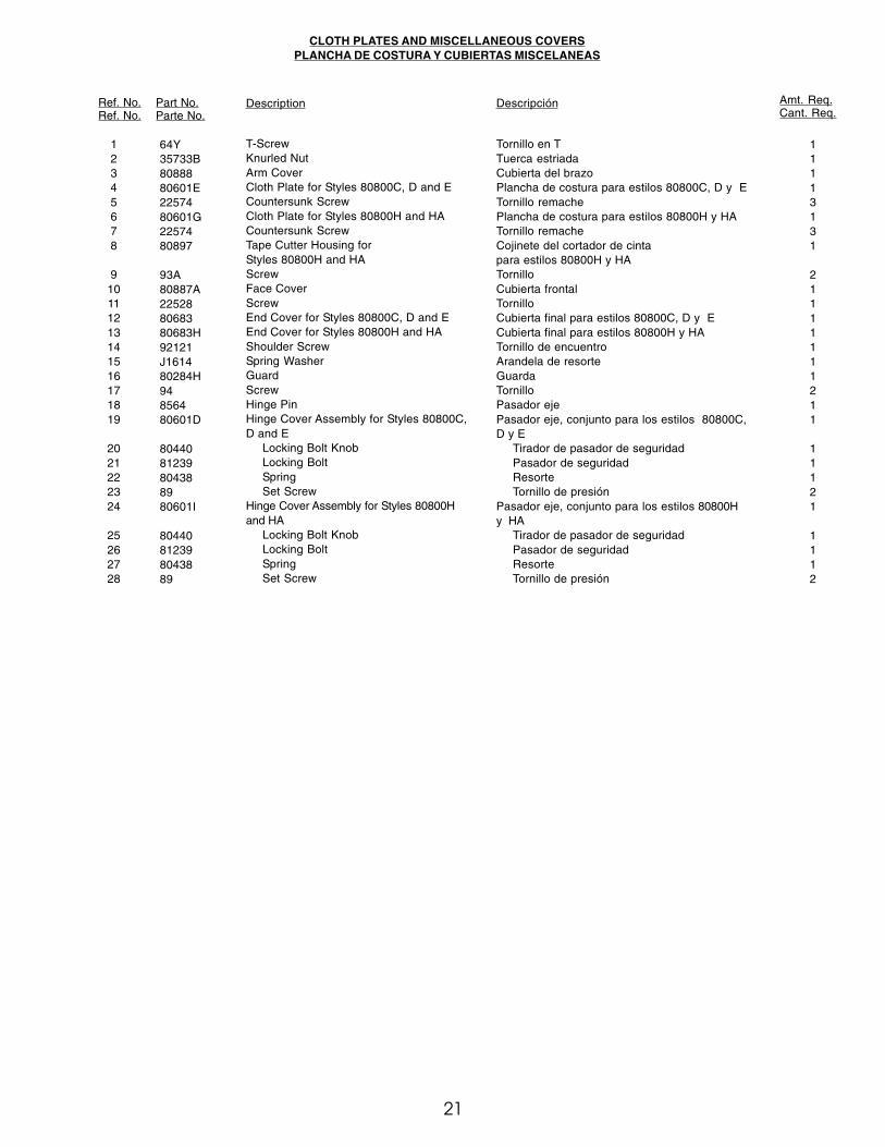
CLOTH PLATES AND MISCELLANEOUS COVERSPLANCHA DE COSTURA Y CUBIERTAS MISCELANEAS
12345678
910111213141516171819
2021222324
25262728
64Y35733B8088880601E2257480601G2257480897
93A80887A225288068380683H92121J161480284H94856480601D
8044081239804388980601I
80440812398043889
T-ScrewKnurled NutArm CoverCloth Plate for Styles 80800C, D and ECountersunk ScrewCloth Plate for Styles 80800H and HACountersunk ScrewTape Cutter Housing forStyles 80800H and HAScrewFace CoverScrewEnd Cover for Styles 80800C, D and EEnd Cover for Styles 80800H and HAShoulder ScrewSpring WasherGuardScrewHinge PinHinge Cover Assembly for Styles 80800C,D and E
Locking Bolt KnobLocking BoltSpringSet Screw
Hinge Cover Assembly for Styles 80800Hand HA
Locking Bolt KnobLocking BoltSpringSet Screw
Tornillo en TTuerca estriadaCubierta del brazoPlancha de costura para estilos 80800C, D y ETornillo remachePlancha de costura para estilos 80800H y HATornillo remacheCojinete del cortador de cintapara estilos 80800H y HATornilloCubierta frontalTornilloCubierta final para estilos 80800C, D y ECubierta final para estilos 80800H y HATornillo de encuentroArandela de resorteGuardaTornilloPasador ejePasador eje, conjunto para los estilos 80800C,D y E
Tirador de pasador de seguridadPasador de seguridadResorteTornillo de presión
Pasador eje, conjunto para los estilos 80800Hy HA
Tirador de pasador de seguridadPasador de seguridadResorteTornillo de presión
11113131
21111111211
11121
1112

22
23
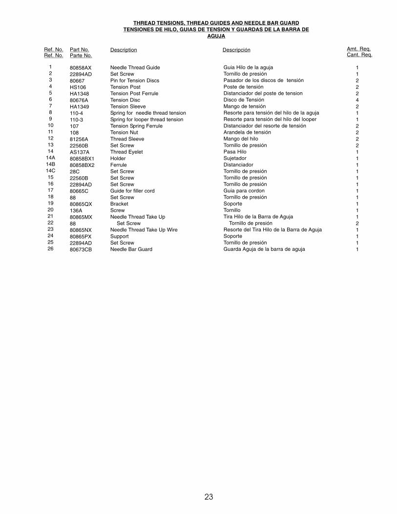
THREAD TENSIONS, THREAD GUIDES AND NEEDLE BAR GUARDTENSIONES DE HILO, GUIAS DE TENSION Y GUARDAS DE LA BARRA DE
AGUJA
Ref. No.Ref. No.
Part No.Parte No.
Description Descripción Amt. Req.Cant. Req.
1234567891011121314
14A14B14C151617181920212223242526
80858AX22894AD80667HS106HA134880676AHA1349110-4110-310710881256A22560BAS137A80858BX180858BX228C22560B22894AD80665C8880865QX136A80865MX8880865NX80865PX22894AD80673CB
Needle Thread GuideSet ScrewPin for Tension DiscsTension PostTension Post FerruleTension DiscTension SleeveSpring for needle thread tensionSpring for looper thread tensionTension Spring FerruleTension NutThread SleeveSet ScrewThread EyeletHolderFerruleSet ScrewSet ScrewSet ScrewGuide for filler cordSet ScrewBracketScrewNeedle Thread Take Up
Set ScrewNeedle Thread Take Up WireSupportSet ScrewNeedle Bar Guard
Guia Hilo de la agujaTornillo de presiónPasador de los discos de tensiónPoste de tensiónDistanciador del poste de tensionDisco de TensiónMango de tensiónResorte para tensión del hilo de la agujaResorte para tensión del hilo del looperDistanciador del resorte de tensiónArandela de tensiónMango del hiloTornillo de presiónPasa HiloSujetadorDistanciadorTornillo de presiónTornillo de presiónTornillo de presiónGuia para cordonTornillo de presiónSoporteTornilloTira Hilo de la Barra de Aguja
Tornillo de presiónResorte del Tira Hilo de la Barra de AgujaSoporteTornillo de presiónGuarda Aguja de la barra de aguja
11222421122221111111111121111
24
25
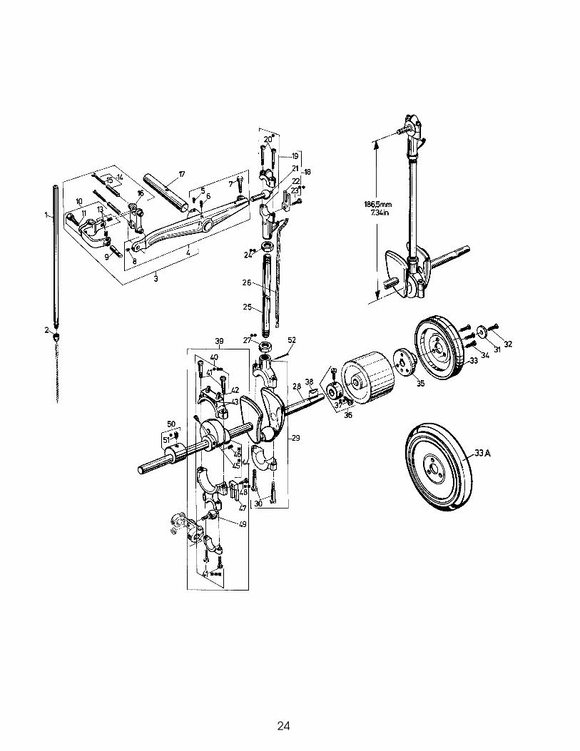
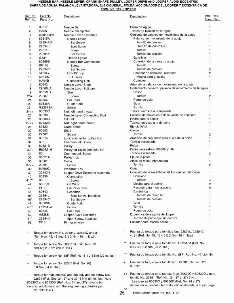
NEEDLE BAR, NEEDLE LEVER, CRANK SHAFT, PULLEY, LOOPER DRIVE AND LOOPER AVOID ECCENTRICBARRA DE AGUJA, PALANCA LEVANTADORA, EJE CIGUEÑAL, POLEA, ACCIONADOR DEL LOOPER Y EXCENTRICA DE
ESQUIVE DEL LOOPER
Ref. No.Ref. No.
Part No.Parte No.
Description Descripción Amt. Req.Cant. Req.
123456789
101113141516171819
20+2122
23**24++
2526
27++282930313233
33A343536
37++383940
41***42434445*46*47
48**495051*52
80617HA56G29479PA80615A22894AD22894K2281122894YG33480659BBP10822894Y51134Y666-260HA54B8064329066LA80650LA225878065680636AG22515A80630C8063080630G80630D808228065222587806748080621BB80621H8080621A8068122891HA66K29442N8023688F666-19PI188064222894L22894C80636AG22515A80645AS38B22894KPI18
Needle BarNeedle Clamp NutNeedle Lever Assembly
Needle LeverSet ScrewSpot ScrewScrewSet Screw
Thread EyeletNeedle Bar Connection
ScrewSet Screw
Link Pin, cyl.Oil Wick
Connecting LinkNeedle Lever ShaftNeedle Lever Ball Link
ShellScrew
Ball StudGuide ForkScrew
Nut, left hand threadNeedle Lever Connecting RodOil FeltNut, right hand threadCrank ShaftShell
ScrewLock Washer for pulley hubCountersunk ScrewPulleyPulley for Styles 80800H, HACountersunk ScrewPulley HubCollar
ScrewWoodruff KeyLooper Drive Eccentric Assembly
ConnectionScrew
Oil WickPin for oil wickEccentric
Spot Screw, headlessSet Screw
Guide ForkScrewBall Stud
Looper Avoid EccentricSpot Screw, headless
Pin for oil wick
Barra de AgujaTuerca de fijación de la agujaConjunto de palanca de movimiento de la aguja
Palanca de movimiento de la agujaTornillo de presión Tornillo de punto fijoTornilloTornillo de presión
Guía-hiloConexión de la barra de aguja
TornilloTornillo de presión
Pasador de conexión, cilíndricoMecha para el aceite
ConectorArbol de la palanca de movimiento de la agujaRodamiento conector palanca de movimiento de la aguja
CascoTornillo
Perno de bolaGuíaTornillo
Tuerca, enrosca a la izquierdaPalanca de movimiento de la varilla de conexiónFieltro para el aceiteTuerca, enrosca a la derechaEje cigüeñalCasco
TornilloArandela de seguridad para el eje de la poleaTornillo avellanadoPoleaPolea para estilos 80800H y HATornillo avellanadoEje de la poleaAnillo de metal; Abrazadera
TornilloCuñaConjunto de la excéntrica del Accionador del looper
ConexiónTornillo
Mecha para el aceitePasador para mecha aceiteExcéntrica
Tornillo de punto fijoTornillo de presión
GuíaTornilloPerno de bola
Excéntrica de esquive del looperTornillo de punto fijo, sin cabeza
Pasador para mecha aceite
1111111111122111112111111111211113112111422111111111
* Torque for screws No. 22894L, 22894C and 81(Ref. Nos. 45, 46 and 51) 2 Nm (18 in. lbs.)
** Torque for screw No. G22515A (Ref. Nos. 23and 48) 2.2 Nm (20 in. lbs.)
*** Torque for screw No. 88F (Ref. No. 41) 2.4 Nm (22 in. lbs.)
+ Torque for screw No. 22587 (Ref. No. 20)3.8 Nm (34 in. lbs.)
++ Torque for nuts 80630C and 80630D and for screw No.22891 (Ref. Nos. 24, 27 and 37) 6 Nm (54 in. lbs.) Nuts
80630C and 80630D (Ref. Nos. 24 and 27) have to besecured additionally with the engineering adhesive part
No. 999-114C.
* Fuerza de torque para tornillos Nrs. 22894L, 22894Cy 81 (Ref. No. 45, 46 y 51) 2 Nm (18 in. lbs.)
** Fuerza de torque para tornillo No. G22515A (Ref. No.23 y 48) 2,2 Nm (20 in. lbs.)
*** Fuerza de torque para tornillo No. 88F (Ref. No. 41) 2,4 Nm
+ Fuerza de torque para tornillo No.. 22587 (Ref. No. 20)3,8 Nm
++ Fuerza de torque para tuercas Nos. 80630C y 80630D y paratornillo No. 22891 (Ref. No. 24, 27 y 37) 6 Nm
Las tuercas 80630C y 80630D (Ref. No. 24 y 27)deben ser ajustadas utilizando adicionalmente la super pega
de construccion, parte No. 999-114C.

26

NEEDLE LEVER ASSEMBLY FOR STYLES 80800E AND HCONJUNTO DE LA PALANCA DE MOVIMIENTO DE LA AGUJA PARA ESTILOS 80800E Y H
Ref. No.Ref. No.
Part No.Parte No.
Description Descripción
THREAD CHAIN CUTTER KNIVES AND CHAIN CUTTER KNIFE DRIVE FOR STYLES 80800C, D AND ECUCHILLAS CORTADORAS DE CADENETA Y MECANISMO CORTADOR DE CADENETA PARA ESTILOS 80800C, D Y E
Ref. No.Ref. No..
Part No.Parte No.
Description Descripción
Amt. Req.Cant.Req.
Amt. Req.Cant.Req.
27
1
23456789
101112131415161718192021222324252627282930
G29479P
29774E80659CBP10822894Y22894W80655HS52B22560HA1286B12964C81086C81093HS100D8066980676HA58CHA58FHA58D800462111122743HA54B51134Y666-26080615A22894YBP1082289422894K
Needle Lever Assembly for Styles80800E and H
Needle Bar Connection AssemblyNeedle Bar Connection
ScrewSet ScrewSet Screw
Thread Guide PinAxle Assembly for Rolling Thread Guide
Set ScrewSpringBallAxle
Thread Guide RollerLocating ScrewTension Post FerruleTension DiscFerruleTension SpringTension Spring FerruleTension PostCollarSet Screw
Connecting LinkLink Pin, cyl.
Oil WickNeedle Lever
Set ScrewScrewSet ScrewSpot Screw, headless
Conjunto de la palanca de movimiento de laaguja, para estilos 80800E und H
Conj. Barra de conexión de laagujaBarra de conexió de l a aguja
TornilloTornillo de presiónTornillo de presión
Pasador del guia hiloConjunto Eje Guía Hilo
Tornillo de presiónResorteBolaEje
Rodillo guia hiloeTornillo de ubicaciónPoste distanciador de tensiónDisco de tensiónDistanciadorResorte de tensiónResorte distanciador de tensiónPoste de tensiónAbrazadera
Tornillo de presiónConectorPasador de conexión, cilíndrico
Mecha de aceiteBarra de aguja
Tornillo de presiónTornilloTornillo de presiónTornillo de presión, sin cabeza
1
11121111111111211111112111111
123456789
101112131415161718192021
29132S1586597A75A8067222894L666-149PI18G10349459806719212798806778067588D446088110-41880670
Connection Assembly for chain cutter driveConnection Bearing
ScrewScrew
EccentricScrew
FeltPinBall Stud
Shaft for chain cutter knifeKnife Bar
Screw for upper knifeScrew
Upper KnifeLower Knife
ScrewCollar
ScrewSpringNutBall Stud Washer
Conj.conexión mecanismo cortador de cadenetaCojinete de conexión
TornilloTornillo
ExcéntricaTornillo
FieltroPasadorPerno de bolas
Eje para la cuchilla cortadora de cadenetaBarra de la cuchilla
Tornillopara cuchilla superiorTornillo
Cuchilla superiorCuchilla inferiorTornilloAbrazadera
TornilloResorteTuercaArandela del perno de bola
112211111111111111111

28
29
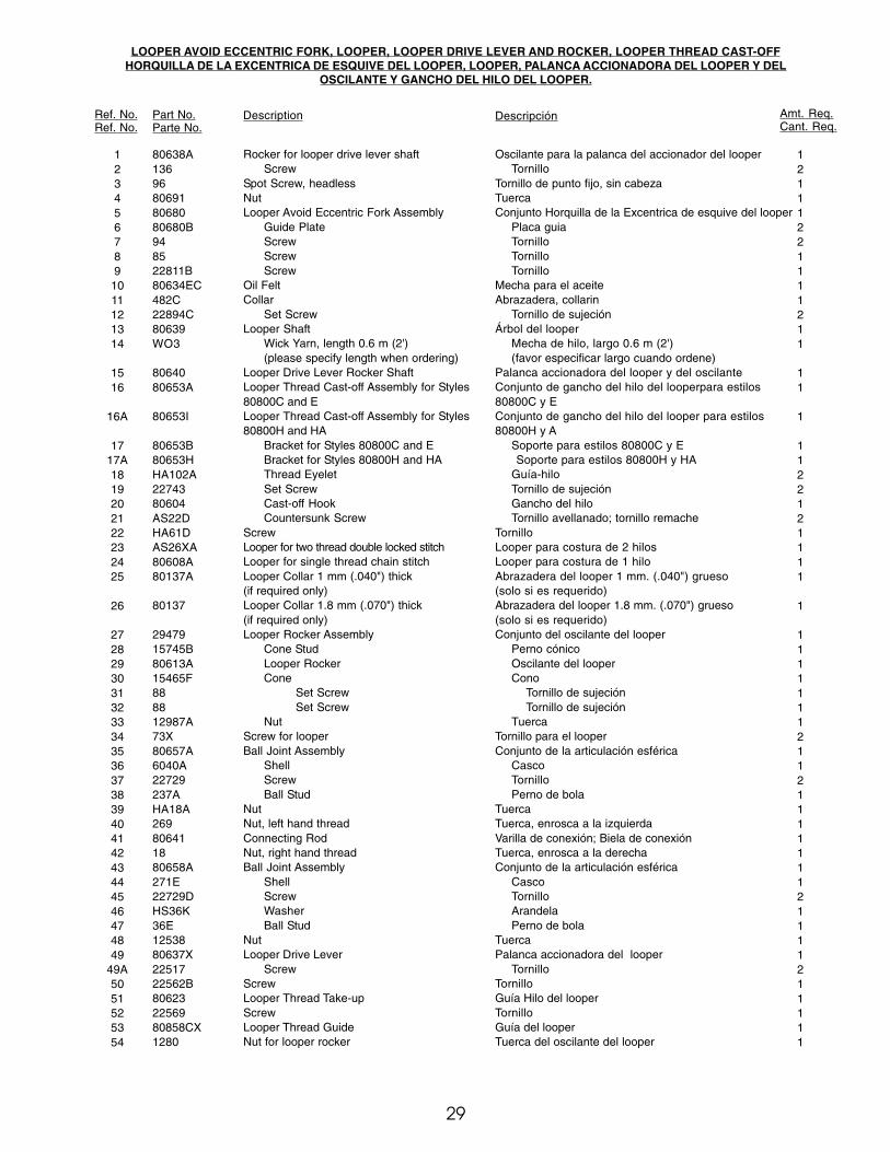
LOOPER AVOID ECCENTRIC FORK, LOOPER, LOOPER DRIVE LEVER AND ROCKER, LOOPER THREAD CAST-OFFHORQUILLA DE LA EXCENTRICA DE ESQUIVE DEL LOOPER, LOOPER, PALANCA ACCIONADORA DEL LOOPER Y DEL
OSCILANTE Y GANCHO DEL HILO DEL LOOPER.
Ref. No.Ref. No.
Part No.Parte No.
Description Descripción Amt. Req.Cant. Req.
123456789
1011121314
1516
16A
1717A1819202122232425
26
2728293031323334353637383940414243444546474849
49A5051525354
80638A13696806918068080680B948522811B80634EC482C22894C80639WO3
8064080653A
80653I
80653B80653HHA102A2274380604AS22DHA61DAS26XA80608A80137A
80137
2947915745B80613A15465F888812987A73X80657A6040A22729237AHA18A269806411880658A271E22729DHS36K36E1253880637X2251722562B806232256980858CX1280
Rocker for looper drive lever shaftScrew
Spot Screw, headlessNutLooper Avoid Eccentric Fork Assembly
Guide PlateScrewScrewScrew
Oil FeltCollar
Set ScrewLooper Shaft
Wick Yarn, length 0.6 m (2')(please specify length when ordering)
Looper Drive Lever Rocker ShaftLooper Thread Cast-off Assembly for Styles80800C and ELooper Thread Cast-off Assembly for Styles80800H and HA
Bracket for Styles 80800C and EBracket for Styles 80800H and HAThread EyeletSet ScrewCast-off HookCountersunk Screw
ScrewLooper for two thread double locked stitchLooper for single thread chain stitchLooper Collar 1 mm (.040") thick(if required only)Looper Collar 1.8 mm (.070") thick(if required only)Looper Rocker Assembly
Cone StudLooper RockerCone
Set ScrewSet Screw
NutScrew for looperBall Joint Assembly
ShellScrewBall Stud
NutNut, left hand threadConnecting RodNut, right hand threadBall Joint Assembly
ShellScrewWasherBall Stud
NutLooper Drive Lever
ScrewScrewLooper Thread Take-upScrewLooper Thread GuideNut for looper rocker
Oscilante para la palanca del accionador del looperTornillo
Tornillo de punto fijo, sin cabezaTuercaConjunto Horquilla de la Excentrica de esquive del looper
Placa guiaTornilloTornilloTornillo
Mecha para el aceiteAbrazadera, collarin
Tornillo de sujeciónÁrbol del looper
Mecha de hilo, largo 0.6 m (2')(favor especificar largo cuando ordene)
Palanca accionadora del looper y del oscilanteConjunto de gancho del hilo del looperpara estilos80800C y EConjunto de gancho del hilo del looper para estilos80800H y A
Soporte para estilos 80800C y E Soporte para estilos 80800H y HA
Guía-hiloTornillo de sujeciónGancho del hiloTornillo avellanado; tornillo remache
TornilloLooper para costura de 2 hilosLooper para costura de 1 hiloAbrazadera del looper 1 mm. (.040") grueso(solo si es requerido)Abrazadera del looper 1.8 mm. (.070") grueso(solo si es requerido)Conjunto del oscilante del looper
Perno cónicoOscilante del looperCono
Tornillo de sujeciónTornillo de sujeción
TuercaTornillo para el looperConjunto de la articulación esférica
CascoTornilloPerno de bola
TuercaTuerca, enrosca a la izquierdaVarilla de conexión; Biela de conexiónTuerca, enrosca a la derechaConjunto de la articulación esférica
CascoTornilloArandelaPerno de bola
TuercaPalanca accionadora del looper
TornilloTornilloGuía Hilo del looperTornilloGuía del looperTuerca del oscilante del looper
12111221111211
11
1
1122121111
1
11111112112111111121111211111
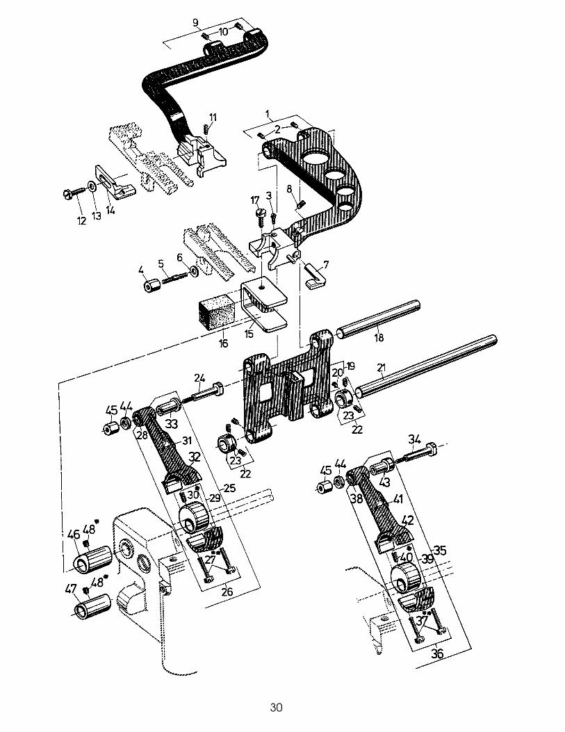
30
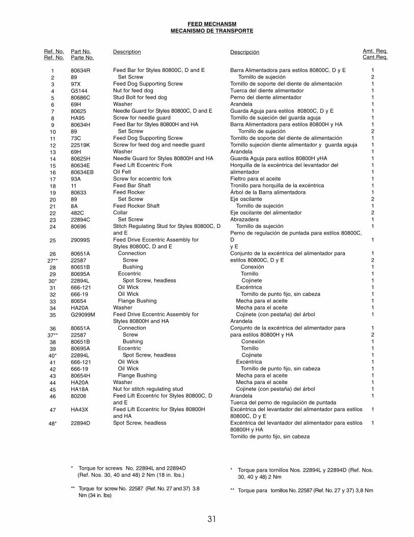
31
FEED MECHANSMMECANISMO DE TRANSPORTE
Ref. No.Ref. No.
Part No.Parte No.
Description Descripción Amt. Req.Cant.Req.
123456789101112131415161718192021222324
25
2627**282930*3132333435
3637**383940*414243444546
47
48*
80634R8997XG514480686C69H80625HA9580634H8973C22519K69H80625H80634E80634EB93A1180633898A482C22894C80696
29099S
80651A2258780651B80695A22894L666-121666-1980654HA20AG29099M
80651A2258780651B80695A22894L666-121666-1980654HHA20AHA18A80206
HA43X
22894D
Feed Bar for Styles 80800C, D and ESet Screw
Feed Dog Supporting ScrewNut for feed dogStud Bolt for feed dogWasherNeedle Guard for Styles 80800C, D and EScrew for needle guardFeed Bar for Styles 80800H and HA
Set ScrewFeed Dog Supporting ScrewScrew for feed dog and needle guardWasherNeedle Guard for Styles 80800H and HAFeed Lift Eccentric ForkOil FeltScrew for eccentric forkFeed Bar ShaftFeed Rocker
Set ScrewFeed Rocker ShaftCollar
Set ScrewStitch Regulating Stud for Styles 80800C, Dand EFeed Drive Eccentric Assembly forStyles 80800C, D and E
ConnectionScrewBushing
EccentricSpot Screw, headless
Oil WickOil WickFlange Bushing
WasherFeed Drive Eccentric Assembly forStyles 80800H and HA
ConnectionScrewBushing
EccentricSpot Screw, headless
Oil WickOil WickFlange Bushing
WasherNut for stitch regulating studFeed Lift Eccentric for Styles 80800C, Dand EFeed Lift Eccentric for Styles 80800Hand HASpot Screw, headless
Barra Alimentadora para estilos 80800C, D y E Tornillo de sujeciónTornillo de soporte del diente de alimentaciónTuerca del diente alimentadorPerno del diente alimentadorArandelaGuarda Aguja para estilos 80800C, D y ETornillo de sujeción del guarda agujaBarra Alimentadora para estilos 80800H y HA Tornillo de sujeciónTornillo de soporte del diente de alimentaciónTornillo sujeción diente alimentador y guarda agujaArandelaGuarda Aguja para estilos 80800H yHAHorquilla de la excéntrica del levantador delalimentadorFieltro para el aceiteTronillo para horquilla de la excéntricaÁrbol de la Barra alimentadoraEje oscilante
Tornillo de sujeciónEje oscilante del alimentadorAbrazadera
Tornillo de sujeciónPerno de regulación de puntada para estilos 80800C,Dy EConjunto de la excéntrica del alimentador paraestilos 80800C, D y E
ConexiónTornillo
CojineteExcéntrica
Tornillo de punto fijo, sin cabezaMecha para el aceiteMecha para el aceiteCojinete (con pestaña) del árbol
ArandelaConjunto de la excéntrica del alimentador parapara estilos 80800H y HA Conexión
Tornillo Cojinete
ExcéntricaTornillo de punto fijo, sin cabeza
Mecha para el aceiteMecha para el aceiteCojinete (con pestaña) del árbol
ArandelaTuerca del perno de regulación de puntadaExcéntrica del levantador del alimentador para estilos80800C, D y EExcéntrica del levantador del alimentador para estilos80800H y HATornillo de punto fijo, sin cabeza
121111111211111111121211
1
1211111111
12111111111
1
1
* Torque for screws No. 22894L and 22894D (Ref. Nos. 30, 40 and 48) 2 Nm (18 in. lbs.)
** Torque for screw No. 22587 (Ref. No. 27 and 37) 3.8Nm (34 in. lbs)
* Torque para tornillos Nos. 22894L y 22894D (Ref. Nos.30, 40 y 48) 2 Nm
** Torque para tornillos No. 22587 (Ref. No. 27 y 37) 3,8 Nm
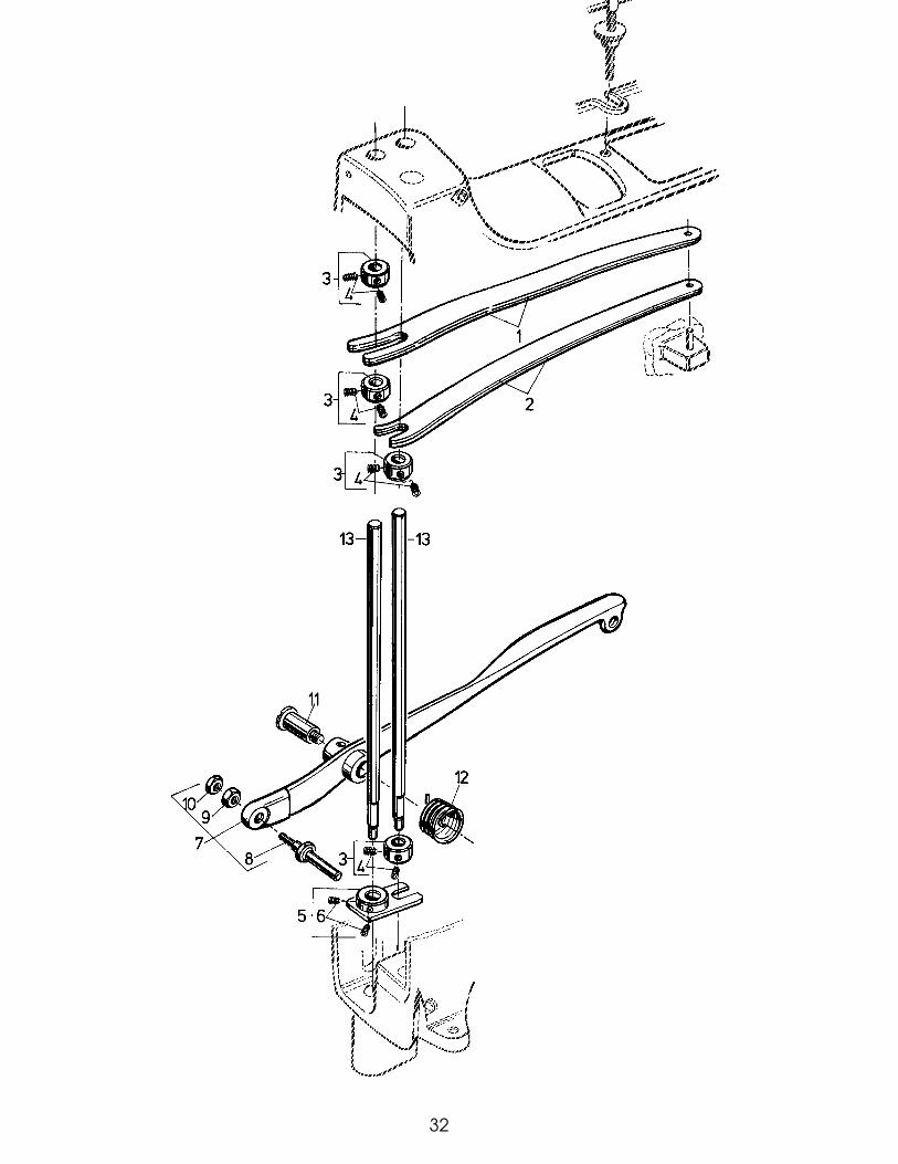
32
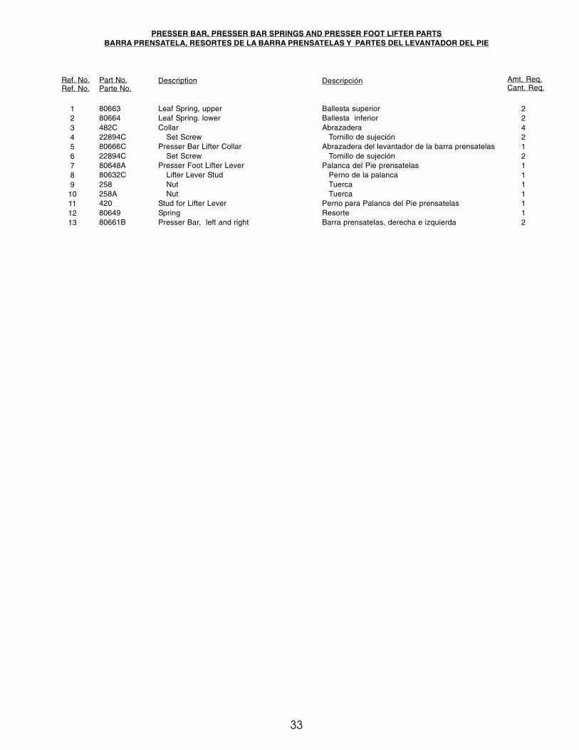
33
PRESSER BAR, PRESSER BAR SPRINGS AND PRESSER FOOT LIFTER PARTSBARRA PRENSATELA, RESORTES DE LA BARRA PRENSATELAS Y PARTES DEL LEVANTADOR DEL PIE
Ref. No.Ref. No.
Part No.Parte No.
Description Descripción Amt. Req.Cant. Req.
123456789
10111213
8066380664482C22894C80666C22894C80648A80632C258258A4208064980661B
Leaf Spring, upperLeaf Spring. lowerCollar
Set ScrewPresser Bar Lifter Collar
Set ScrewPresser Foot Lifter Lever
Lifter Lever StudNutNut
Stud for Lifter LeverSpringPresser Bar, left and right
Ballesta superiorBallesta inferiorAbrazadera
Tornillo de sujeciónAbrazadera del levantador de la barra prensatelas
Tornillo de sujeciónPalanca del Pie prensatelas
Perno de la palancaTuercaTuerca
Perno para Palanca del Pie prensatelasResorteBarra prensatelas, derecha e izquierda
2242121111112

34
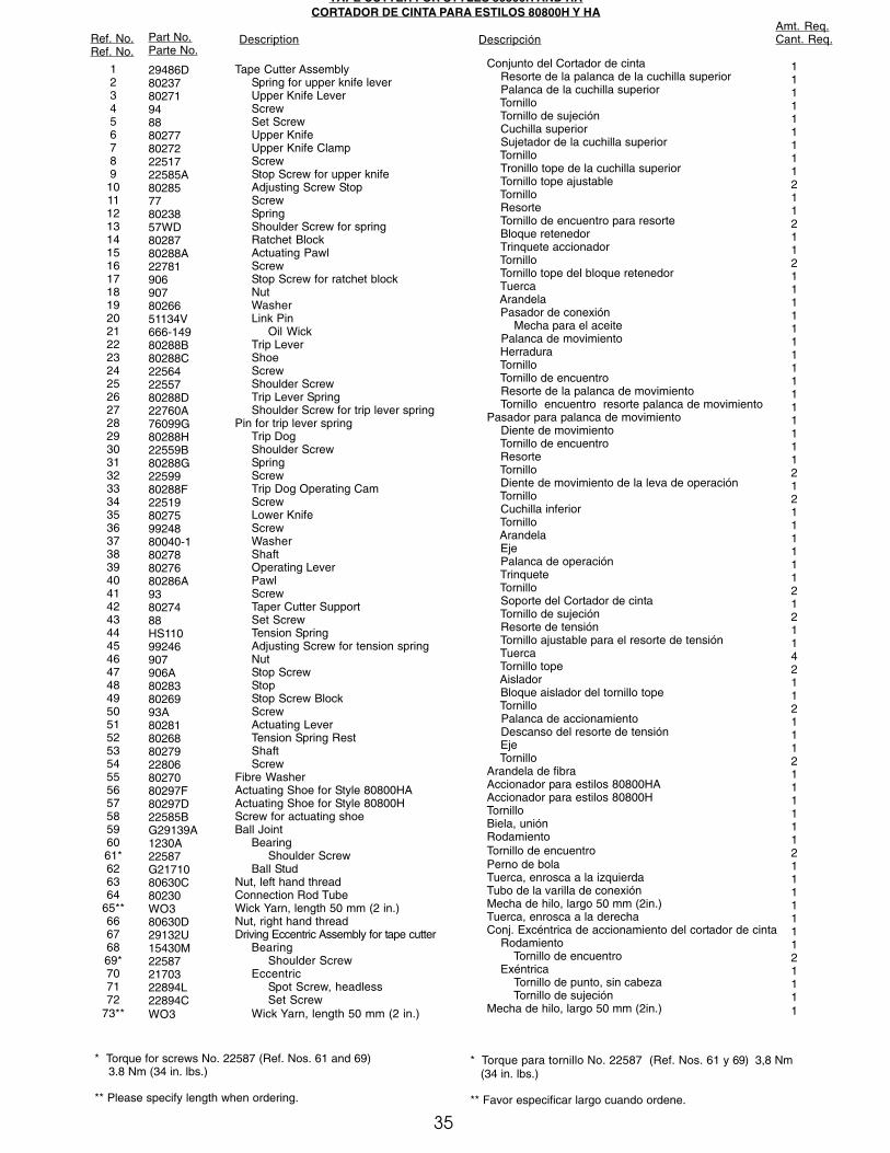
35
TAPE CUTTER FOR STYLES 80800H AND HACORTADOR DE CINTA PARA ESTILOS 80800H Y HA
Ref. No.Ref. No.
Part No.Parte No.
Description DescripciónAmt. Req.Cant. Req.
123456789
10111213141516171819202122232425262728293031323334353637383940414243444546474849505152535455565758596061*626364
65**66676869*707172
73**
29486D8023780271948880277802722251722585A80285778023857WD8028780288A227819069078026651134V666-14980288B80288C225642255780288D22760A76099G80288H22559B80288G2259980288F22519802759924880040-1802788027680286A938027488HS11099246907906A802838026993A802818026880279228068027080297F80297D22585BG29139A1230A22587G2171080630C80230WO380630D29132U15430M225872170322894L22894CWO3
Tape Cutter AssemblySpring for upper knife leverUpper Knife LeverScrewSet ScrewUpper KnifeUpper Knife ClampScrewStop Screw for upper knifeAdjusting Screw StopScrewSpringShoulder Screw for springRatchet BlockActuating PawlScrewStop Screw for ratchet blockNutWasherLink Pin
Oil WickTrip LeverShoeScrewShoulder ScrewTrip Lever SpringShoulder Screw for trip lever spring
Pin for trip lever springTrip DogShoulder ScrewSpringScrewTrip Dog Operating CamScrewLower KnifeScrewWasherShaftOperating LeverPawlScrewTaper Cutter SupportSet ScrewTension SpringAdjusting Screw for tension springNutStop ScrewStopStop Screw BlockScrewActuating LeverTension Spring RestShaftScrew
Fibre WasherActuating Shoe for Style 80800HAActuating Shoe for Style 80800HScrew for actuating shoeBall Joint
BearingShoulder Screw
Ball StudNut, left hand threadConnection Rod TubeWick Yarn, length 50 mm (2 in.)Nut, right hand threadDriving Eccentric Assembly for tape cutter
BearingShoulder Screw
EccentricSpot Screw, headlessSet Screw
Wick Yarn, length 50 mm (2 in.)
Conjunto del Cortador de cinta Resorte de la palanca de la cuchilla superior Palanca de la cuchilla superior Tornillo Tornillo de sujeción Cuchilla superior Sujetador de la cuchilla superior Tornillo Tronillo tope de la cuchilla superior Tornillo tope ajustable Tornillo Resorte Tornillo de encuentro para resorte Bloque retenedor Trinquete accionador Tornillo Tornillo tope del bloque retenedor Tuerca Arandela Pasador de conexión Mecha para el aceite Palanca de movimiento Herradura Tornillo Tornillo de encuentro Resorte de la palanca de movimiento Tornillo encuentro resorte palanca de movimientoPasador para palanca de movimiento Diente de movimiento Tornillo de encuentro Resorte Tornillo Diente de movimiento de la leva de operación Tornillo Cuchilla inferior Tornillo Arandela Eje Palanca de operación Trinquete Tornillo Soporte del Cortador de cinta Tornillo de sujeción Resorte de tensión Tornillo ajustable para el resorte de tensión Tuerca Tornillo tope Aislador Bloque aislador del tornillo tope Tornillo Palanca de accionamiento Descanso del resorte de tensión Eje TornilloArandela de fibraAccionador para estilos 80800HAAccionador para estilos 80800HTornilloBiela, uniónRodamientoTornillo de encuentroPerno de bolaTuerca, enrosca a la izquierdaTubo de la varilla de conexiónMecha de hilo, largo 50 mm (2in.)Tuerca, enrosca a la derechaConj. Excéntrica de accionamiento del cortador de cinta Rodamiento Tornillo de encuentro Exéntrica Tornillo de punto, sin cabeza Tornillo de sujeciónMecha de hilo, largo 50 mm (2in.)
1111111112112112111111111111111212111111212114211211121111112111111121111
* Torque for screws No. 22587 (Ref. Nos. 61 and 69) 3.8 Nm (34 in. lbs.)
** Please specify length when ordering.
* Torque para tornillo No. 22587 (Ref. Nos. 61 y 69) 3,8 Nm (34 in. lbs.)
** Favor especificar largo cuando ordene.
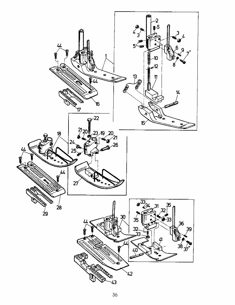
36
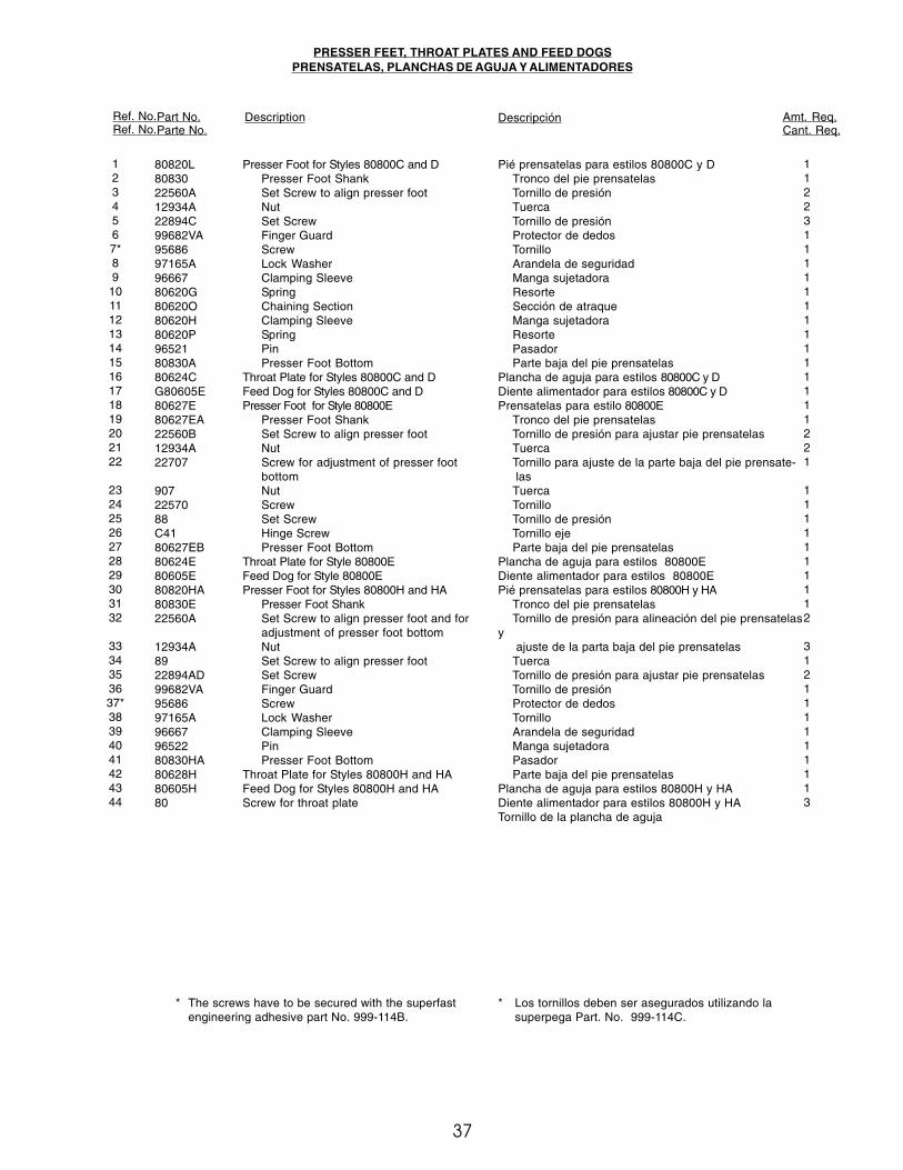
37
PRESSER FEET, THROAT PLATES AND FEED DOGSPRENSATELAS, PLANCHAS DE AGUJA Y ALIMENTADORES
Ref. No.Ref. No.
Part No.Parte No.
Description Descripción Amt. Req.Cant. Req.
* The screws have to be secured with the superfastengineering adhesive part No. 999-114B.
* Los tornillos deben ser asegurados utilizando lasuperpega Part. No. 999-114C.
1234567*89
10111213141516171819202122
23242526272829303132
3334353637*38394041424344
80820L8083022560A12934A22894C99682VA9568697165A9666780620G80620O80620H80620P9652180830A80624CG80605E80627E80627EA22560B12934A22707
9072257088C4180627EB80624E80605E80820HA80830E22560A
12934A8922894AD99682VA9568697165A966679652280830HA80628H80605H80
Presser Foot for Styles 80800C and DPresser Foot ShankSet Screw to align presser footNutSet ScrewFinger GuardScrewLock WasherClamping SleeveSpringChaining SectionClamping SleeveSpringPinPresser Foot Bottom
Throat Plate for Styles 80800C and DFeed Dog for Styles 80800C and DPresser Foot for Style 80800E
Presser Foot ShankSet Screw to align presser footNutScrew for adjustment of presser footbottomNutScrewSet ScrewHinge ScrewPresser Foot Bottom
Throat Plate for Style 80800EFeed Dog for Style 80800EPresser Foot for Styles 80800H and HA
Presser Foot ShankSet Screw to align presser foot and foradjustment of presser foot bottomNutSet Screw to align presser footSet ScrewFinger GuardScrewLock WasherClamping SleevePinPresser Foot Bottom
Throat Plate for Styles 80800H and HAFeed Dog for Styles 80800H and HAScrew for throat plate
Pié prensatelas para estilos 80800C y DTronco del pie prensatelasTornillo de presiónTuercaTornillo de presiónProtector de dedosTornilloArandela de seguridadManga sujetadoraResorteSección de atraqueManga sujetadoraResortePasadorParte baja del pie prensatelas
Plancha de aguja para estilos 80800C y DDiente alimentador para estilos 80800C y DPrensatelas para estilo 80800E
Tronco del pie prensatelasTornillo de presión para ajustar pie prensatelasTuercaTornillo para ajuste de la parte baja del pie prensate-
lasTuercaTornilloTornillo de presiónTornillo ejeParte baja del pie prensatelas
Plancha de aguja para estilos 80800EDiente alimentador para estilos 80800EPié prensatelas para estilos 80800H y HA
Tronco del pie prensatelasTornillo de presión para alineación del pie prensatelas
y ajuste de la parta baja del pie prensatelas
TuercaTornillo de presión para ajustar pie prensatelasTornillo de presiónProtector de dedosTornilloArandela de seguridadManga sujetadoraPasadorParte baja del pie prensatelas
Plancha de aguja para estilos 80800H y HADiente alimentador para estilos 80800H y HATornillo de la plancha de aguja
1122311111111111111221
1111111112
312111111113
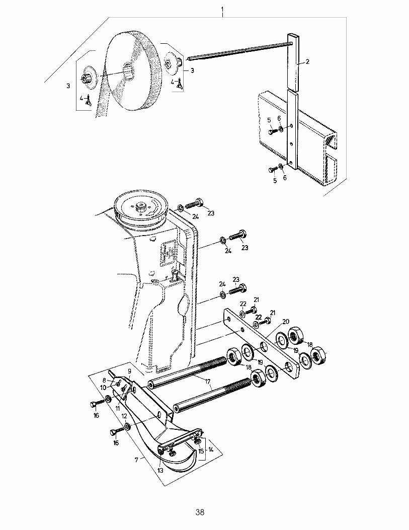
38

39
Ref. No.Pos. Nr.
Part No.Teil Nr.
Description Descripción Amt. Req.Cant. Req.
789
101112131415161718192021222324
G23451G23451VG23451H9469HHA20B97160G23451A188DBP10823451M990081635UG11667VB950541021U80463A96203
Tape Folder AssemblyEdge Guide for tape, frontEdge Guide for tape, rearScrewWasherWasherRetaining RingCollar
Thumb ScrewScrew for tape folderTape Folder Support RodNutWasherMounting PlateScrewWasherMachine Fastening ScrewLocking Ring
Conjunto del dobladilladorGuía de borde para la cinta, frontalGuía de borde para la cinta, posteriorTornilloArandelaArandelaAro retenedorAbrazadera
Tornillo de manoTornillo para el dobladilladorVarilla de soporte del dobladillador de cintaTuercaArandelaPlaca de montajeTornilloArandelaTornillo asegurador de la maquinaArandela de seguridad
111442221224412233
TAPE FOLDER FOR STYLE 80800HAMACHINE FASTENING SCREWS
DOBLADILLADOR PARA ESTILO 80800HATORNILLOS ASEGURADORES DE MAQUINA
TAPE REEL ASSEMBLY FOR STYLE 80800HACONJUNTO RUEDA DISPENSADORA DE CINTA, PARA ESTILO 80800HA
123456
29480XR93064M93064MA955559505596203
Tape Reel AssemblyTape ReelTape Reel Guide
ScrewScrewWasher, lock
Conjunto rueda dispensadora de cintaDispensador de cintaGuia del dispensador de cinta
TornilloTornilloArandela de seguridad
112122
Ref. No.Ref. No.
Part No.Parte No.
Description Descripción Amt. Req.Cant. Req.

40
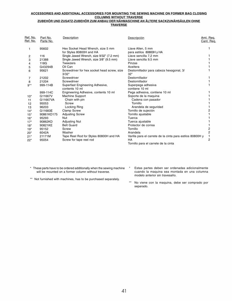
41
ACCESSORIES AND ADDITIONAL ACCESSORIES FOR MOUNTING THE SEWING MACHINE ON FORMER BAG CLOSINGCOLUMNS WITHOUT TRAVERSE
ZUBEHÖR UND ZUSATZ-ZUBEHÖR ZUM ANBAU DER NÄHMASCHINE AN ÄLTERE SACKZUNÄHSÄULEN OHNETRAVERSE
Ref. No.Ref. No.
Part No.Parte No.
Description Descripción Amt. Req.Cant. Req.
1
23456
78
9**
10*11121314*15*16*17*18*19*20*21*22*
95602
11621388118GG43294B95621
2120221204999-114B
999-114CG11667VG11667VA9505396203G11683E90861KD1759529390862KD90821KE951526042A21171M95054
Hex Socket Head Wrench, size 5 mmfor Styles 80800H and HASingle Jawed Wrench, size 9/32" (7.2 mm)Single Jawed Wrench, size 3/8" (9.5 mm)TweezersOil CanScrewdriver for hex socket head screw, size3/32"ScrewdriverScrewdriverSuperfast Engineering Adhesive,contents 10 mlEngineering Adhesive, contents 10 mlMachine Support
Chain with pinScrewLocking Ring
Clamp ScrewAdjusting ScrewNutAdjusting NutBelt GuardScrewWasherTape Reel Rod for Styles 80800H and HAScrew for tape reel rod
Llave Allen, 5 mmpara estilos 80800H y HALlave sencilla 7,2 mmLlave sencilla 9,5 mmPinzasAceiteraDestornillador para cabeza hexagonal, 3/32"DestornilladorDestornilladorSuperpega adhesivacontiene 10 mlPega adhesiva, contiene 10 mlSoporte de la maquina
Cadena con pasadorTornilloArandela de seguridad
Tornillo de sujeciónTornillo ajustableTuercaTuerca ajustableProtector de correaTornilloArandelaVarilla para el carrete de la cinta para estilos 80800H yHATornillo para el carrete de la cinta
1
11111
111
11111211112212
* These parts have to be ordered additionally when the sewing machinewill be mounted on a former column without traverse.
** Not furnished with machines, has to be purchased separately.
* Estas partes deben ser ordenadas adicionalmentecuando la maquina sea montada en una columnamodelo anterior sin travesaño.
** No viene con la maquina, debe ser comprado porseparado.

NUMERICAL INDEX OF PARTSINDICE NUMERICO DE PARTES
42
Part No.Parte No.
PagePág.
Part No.Parte No.
PagePág.
Part No.Parte No.
PagePág.
Part No.Parte No.
PagePág.
1021U ... 39107 ... 23108 ... 2311 ... 31110-3 ... 23110-4 ... 23116 ... 41118G ... 411230A ... 3512538 ... 291280 ... 2912934A ... 3712964C ... 2712987A ... 29136 ... 29136A ... 2315430M ... 3515465F ... 2915745B ... 291635U ... 3918 ... 29188D ... 3921111 ... 2721171M ... 4121202 ... 4121204 ... 4121388 ... 4121703 ... 3522517 ... 29, 3522519 ... 3522519K ... 3122528 ... 2122539 ... 1922557 ... 3522559B ... 3522560 ... 2722560A ... 3722560B ... 23, 3722564 ... 3522569 ... 2922570 ... 3722574 ... 2122585A ... 3522585B ... 3522587 ... 25, 31, 3522596D ... 1922599 ... 3522707 ... 3722729 ... 2922729D ... 2922743 ... 27, 2922760A ... 3522781 ... 3522806 ... 3522811 ... 2522811B ... 2922842 ... 2122891 ... 19, 2522894 ... 27
22894AD ... 23, 25, 3722894C ... 25, 29, 31, 33, 35, 3722894D ... 3122894J ... 1922894K ... 19, 25, 2722894L ... 25, 31, 3522894W ... 2722894Y ... 25, 2723451M ... 39237A ... 29258 ... 33258A ... 33269 ... 29271E ... 2928C ... 2329066LA ... 2529099S ... 3129132U ... 3529442N ... 2529479 ... 2929480XR ... 3929774E ... 2729916REB ... 1929916REE ... 1929925 ... 3535733B ... 2136E ... 29420 ... 33482C ... 29, 31, 3351134V ... 25, 3551134Y ... 2757WD ... 356040A ... 296042A ... 4164Y ... 21666-121 ... 31666-149 ... 35666-19 ... 25, 31666-260 ... 25, 27666-79 ... 1969H ... 19, 31, 3973C ... 3173X ... 2976099G ... 3577 ... 3579048 ... 1980 ... 25, 3780040-1 ... 3580046 ... 2780137 ... 2980137A ... 2980206 ... 3180230 ... 3580236 ... 2580237 ... 3580238 ... 3580266 ... 3580268 ... 3580269 ... 35
80270 ... 3580271 ... 3580272 ... 3580274 ... 3580275 ... 3580276 ... 3580277 ... 3580278 ... 3580279 ... 3580281 ... 3580283 ... 3580284H ... 2180285 ... 3580286A ... 3580287 ... 3580288A ... 3580288B ... 3580288C ... 3580288D ... 3580288F ... 3580288G ... 3580288H ... 3580293A ... 1980297D ... 3580297F ... 3580438 ... 2180440 ... 2180463A ... 3980601D ... 2180604 ... 2980605E ... 3780605H ... 3780608A ... 2980613A ... 2980615A ... 25, 2780617 ... 2580620G ... 3780620H ... 3780620P ... 3780621A ... 2580621B ... 2580623 ... 2980624E ... 3780625 ... 3180625H ... 3180627E ... 3780627EA ... 3780627EB ... 3780627T ... 3780628H ... 3780630 ... 2580630C ... 25, 3580630D ... 25, 3580630G ... 2580632C ... 3380633 ... 3180634E ... 3180634EB ... 3180634EC ... 29
80634H ... 3180634R ... 3180636A ... 2580637 ... 2980638A ... 2980639 ... 2980639EA ... 1980639FA ... 1980640 ... 2980640EA ... 1980641 ... 2980642 ... 2580643 ... 2580644 ... 1980645 ... 2580648A ... 3380649 ... 3380650LA ... 2580651A ... 3180651B ... 3180652 ... 2580653A ... 2980653B ... 2980653H ... 2980653I ... 2980654 ... 3180655 ... 2780656 ... 2580657A ... 2980658A ... 2980659B ... 2580659C ... 2780661B ... 3380663 ... 3380664 ... 3380665C ... 2380666C ... 3380667 ... 19, 2380669 ... 2780673B ... 1980673CB ... 2380674 ... 2580676 ... 2780676A ... 2380680 ... 2980680B ... 2980681 ... 2580682R ... 2180683H ... 2180686C ... 3180689C ... 1980689D ... 1980691 ... 2980692DA ... 1980692EA ... 1980694DA ... 1980695A ... 3180696 ... 3180698A ... 19

43
NUMERICAL INDEX OF PARTSINDICE NUMERICO DE PARTES
Part No.Parte No.
PagePág.
Part No.Parte No.
PagePág.
Part No.Parte No.
PagePág.
Part No.Parte No.
PagePág.
80801R ... 2180801TA ... 2180801U ... 2180820HA ... 3780822 ... 2580827R ... 3780830 ... 3780830B ... 3780830E ... 3780830HA ... 3780846 ... 1980858AX ... 2380858BX1 ... 2380858BX2 ... 2380858CX ... 2980862 ... 1980865MX ... 2380865NX ... 2380865PX ... 2380865QX ... 2380885 ... 1980885A ... 1980885B ... 1980885C ... 1980887A ... 2180888 ... 2180897 ... 2180898A ... 1981086C ... 2781093 ... 2781239 ... 2181256A ... 2385 ... 298564 ... 2188 ... 19, 23, 29, 35, 3788F ... 2589 ... 19, 21, 31, 378A ... 31906 ... 35906A ... 35907 ... 35, 3790821KE ... 4190861KD175 ... 4190862KD ... 4192121 ... 2193 ... 3593064M ... 3993064MA ... 3993A ... 21, 31, 3594 ... 21, 29, 35, 3995053 ... 4195054 ... 39, 4195055 ... 3995152 ... 4195293 ... 4195555 ... 3995602 ... 4195621 ... 4195686 ... 37
95861 ... 1996 ... 2996203 ... 39, 4196522 ... 3796657 ... 1996667 ... 3796815 ... 3797160 ... 3997165A ... 3797X ... 3199008 ... 3999246 ... 3599248 ... 3599682VA ... 37999-106D ... 19999-114B ... 19, 41999-114C ... 41
AS137A ... 23AS22D ... 29AS26XA ... 29AS38B ... 25
B80621H ... 25BP108 ... 25, 27, 39
C41 ... 37
G11667V ... 41G11667VA ... 41G11667VB ... 39G11683E ... 41G21710 ... 35G22515A ... 25G23451 ... 39G23451A ... 39G23451H ... 39G23451V ... 39G29139A ... 35G29479P ... 27G29479PA ... 25G334 ... 25G41046G ... 19G43294B ... 41G5144 ... 31G80605E ... 37
HA102A ... 29HA1286B ... 27HA1348 ... 23HA1349 ... 23HA18A ... 29, 31HA20A ... 31HA20B ... 39
HA43X ... 31HA54B ... 25, 27HA56 ... 25HA58C ... 27HA58D ... 27HA58F ... 27HA61D ... 29HA66K ... 25HA81 ... 19HA95 ... 19, 31HS100D ... 27HS106 ... 23HS110 ... 35HS36K ... 29HS52B ... 27
J1614 ... 21
M129C ... 19M129K ... 19
PI18 ... 25
WO3 ... 19, 29, 35
