illustrated installation instructions - piersolutions.net shade and making final cuts after boards...
TRANSCRIPT

Illustrated Installation Instructions

Notes
2

Table of Contents
3
General Introduction . . . . . . . . . . . . . . . . . . 4Local Building Codes . . . . . . . . . . . . . . . . 4
Scheduling Your Project . . . . . . . . . . . . . . . 4Unloading, Storage, and Handling . . . . . . 4Cautions . . . . . . . . . . . . . . . . . . . . . . . . . . 4Expansion and Contraction . . . . . . . . . . . 4
Sub-Structure Framing . . . . . . . . . . . . . . . . 5Installing Feature and Perimeter Strips . . 5Joist Spacing . . . . . . . . . . . . . . . . . . . . . . . 5Under-Deck Ventilation . . . . . . . . . . . . . . . 6Deck Drainage . . . . . . . . . . . . . . . . . . . . . . 6
General Guidelines . . . . . . . . . . . . . . . . . . . 6Tools Needed . . . . . . . . . . . . . . . . . . . . . . 6Board Layout . . . . . . . . . . . . . . . . . . . . . . . 6GeoDeck Board Spacing . . . . . . . . . . . . . 6Traditional or Commercial Gapping . . . . . 7Tongue & Groove Gapping . . . . . . . . . . . 7Gapping of Mitered Joints . . . . . . . . . . . . 7Fasteners . . . . . . . . . . . . . . . . . . . . . . . . . . 7
Installation . . . . . . . . . . . . . . . . . . . . . . . . . . . 9Parallel or Perpendicular Decking . . . . . . 9Diagonal Decking . . . . . . . . . . . . . . . . . . 10Feature and Perimeter Strips . . . . . . . . . 11Railing System . . . . . . . . . . . . . . . . . . . . . 11Stair Treads and Risers . . . . . . . . . . . . . . 14Stair Railing . . . . . . . . . . . . . . . . . . . . . . . 15Fascia Boards . . . . . . . . . . . . . . . . . . . . . 16
Cleaning . . . . . . . . . . . . . . . . . . . . . . . . . . . . 17
Warranty . . . . . . . . . . . . . . . . . . . . . . . . . . . . 18

Store Flat
Do Not Burn
No Dumping
Protective Gear
Scheduling Your Project
Unloading, Storage, and Handling of GeoDeck
GeoDeck boards should be stored on a dry, flat surface andsupported every 24 inches. Do not stack GeoDeck more thanfour skids high. Cutting and drilling of GeoDeck does notproduce respirable dust, but it is a good practice to alwayswear protective equipment such as safety glasses and hearingprotection when operating power equipment.
Expansion and Contraction
Every material expands and contracts with temperaturechanges, and composite decking is no exception. Avoidpotential problems by budgeting time for proper acclimationof GeoDeck to local temperatures.
It is best to mark, cut, and install boards when they are all atroughly the same temperature. Boards that have spent severalhours in the sun will have expanded more than those kept inthe shade, and consequently will contract more when theycool down.
If possible, schedule construction to take place during the timeof the average daytime temperature. On extremely hot days(90°F+), steps should be taken to reduce the effect ofcontraction as the boards cool, such as storing boards in the shade and making final cuts after boards have cooled.
Allow for gapping when joining GeoDeck decking from end to end.
General Introduction
GeoDeck® is a state-of-the-art deck and railing system that will give you years of ageless beauty and carefree enjoyment.
GeoDeck boards come in:
•Three colors: Cedar, Driftwood, and Mahogany •Three profiles: Traditional, Tongue & Groove, and Heavy-Duty Commercial
•Three lengths: 12’, 16’, and 20’
The complete GeoDeck system includes boards, post sleeves,railings, balusters, end caps, post caps, post base trim, andhandrail collars — everything needed to create a great-looking deck.
Since GeoDeck is manufactured from recycled cellulose fiber,plastics, and minerals, its properties differ from those of woodproducts. So naturally, it has different handling and installationrequirements, which need to be taken into considerationduring the planning of your deck before you start installation.The following illustrated instructions have been provided tohelp you understand and take advantage of these differenceswith appropriate installation techniques. Following theseinstructions along with good building practices will deliver thehighest quality installation. Failure to follow these instructionsalso risks voiding the GeoDeck warranty.
Local Building Codes
Follow all local codes and good construction practices whendesigning and installing the deck sub-structure. Most municipalbuilding codes have specific deck construction requirements.Failure to follow local building codes, including filing plans andscheduling inspections with the municipal building inspector,may result in costly post-construction modifications. There aremany excellent deck construction books on the market, manyof which are available at your local lumberyard. In addition tolocal codes, be sure to follow the instructions in this manualthat specifically pertain to the GeoDeck products. Failure to doso may void your GeoDeck warranty.
4
NOTE: If the outside temperature is greater than60°F, butt boards together tightly. For temperaturesless than 60°F, leave 1/16” gap between boards. Thelonger the board, the more it may contract.
Cautions

5
Installing Feature and Perimeter Strips
Layout your deck using standard framing techniques. Thecutaway detail below shows the joist, 2x4 spacer, and blockingborder. This framing allows the GeoDeck boards and thePerimeter Strips a solid foundation to rest on.
The following two illustrations show how to complete a cornerwith and without a post using the same framing techniques.
Sub-Structure Framing
2x4 Spacer
Blocking
Outer Joist
Joist
Cutaway DetailCutaway DetailCutaway Detail
The intermediate joist is the framing necessary for Feature Strips.
Center blocking ties the joist together to complete the framing.
Joist Spacing
Joists should be spaced no more than 24” on center. Inapplications of prolonged direct sunlight or in southernclimates, use 16” on center joist spacing to reduce deflectionbetween joists. If applying deck boards diagonally across joists, the joist spacing should be reduced by 4”. Heavy-DutyCommercial boards may be used diagonally on joists spaced 24” on center. Be certain that the joist system is properlysquared and secured with center blocking.
Intermediate Joists
Intermediate JoistIntermediate JoistIntermediate Joist
2x4 Spacer
Feature Strip
Center Blocking Center Blocking
Blocking
Blocking
2x4 Spacer
Joist
Corner Without PostCorner Without PostCorner Without Post
Perimeter Strip
Blocking 2x4 Spacer
Joist
Corner With PostCorner With PostCorner With Post
Perimeter Strip
6
Sub-Structure Framing
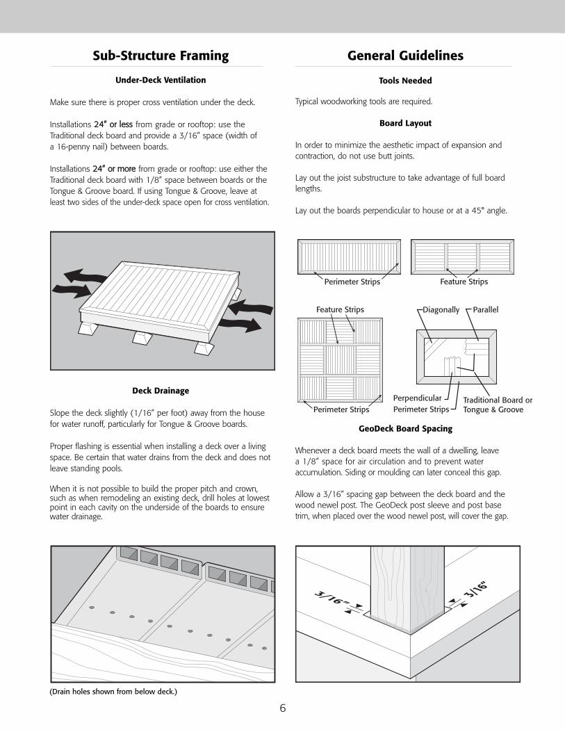
Under-Deck Ventilation
Make sure there is proper cross ventilation under the deck.
Installations 2244”” oorr lleessss from grade or rooftop: use theTraditional deck board and provide a 3/16” space (width of a 16-penny nail) between boards.
Installations 2244”” oorr mmoorree from grade or rooftop: use either theTraditional deck board with 1/8” space between boards or theTongue & Groove board. If using Tongue & Groove, leave atleast two sides of the under-deck space open for cross ventilation.
Deck Drainage
Slope the deck slightly (1/16” per foot) away from the housefor water runoff, particularly for Tongue & Groove boards.
Proper flashing is essential when installing a deck over a livingspace. Be certain that water drains from the deck and does notleave standing pools.
When it is not possible to build the proper pitch and crown,such as when remodeling an existing deck, drill holes at lowestpoint in each cavity on the underside of the boards to ensurewater drainage.
General Guidelines
Tools Needed
Typical woodworking tools are required.
Board Layout
In order to minimize the aesthetic impact of expansion andcontraction, do not use butt joints.
Lay out the joist substructure to take advantage of full boardlengths.
Lay out the boards perpendicular to house or at a 45° angle.
GeoDeck Board Spacing
Whenever a deck board meets the wall of a dwelling, leave a 1/8” space for air circulation and to prevent wateraccumulation. Siding or moulding can later conceal this gap.
Allow a 3/16” spacing gap between the deck board and thewood newel post. The GeoDeck post sleeve and post basetrim, when placed over the wood newel post, will cover the gap.
Feature Strips
Diagonally
Perimeter Strips
Perimeter Strips
Perpendicular Traditional Board orTongue & Groove
ParallelFeature Strips
Perimeter Strips
3/16”3/16”
(Drain holes shown from below deck.)

7
Traditional or Commercial Gapping
Keep the deck boards square as you proceed. Check for square-ness every few boards and adjust the board-to-board gap asnecessary to compensate. Maintain a minimum board-to-boardgap to assure proper drainage of rain and snow melt.
Tongue & Groove Gapping
The installation of Tongue & Groove boards is similar to that of Traditional and Commercial boards with a few exceptions. Do not force Tongue & Groove boards together. Hand fit only,using a credit card or an item of similar thickness (~1/32”) as a spacing guide. An installation that is too tight will restrictwater runoff and may cause buckling.
Gapping of Mitered Joints
Mitered joints at the corners are required. However, sometimesbutt joints may be necessary when the Perimeter Strip isn’tlong enough. In this case, place the butt joint next to a verticalrail post. To create the butt joint, use a router bit or handdrywall shaper to chamfer the edge. Make sure to leave 3/16”between the butted Perimeter Strips.
Fasteners
Traditional: Use 8d 2 1/2” stainless or acceptably coated ringshank nails. A coil drum ring siding/fencing pneumatic nailerspeeds the installation dramatically. If using screws, use a #9,2 1/2” stainless (or coated) trim head screw. Apply a minimumof two fasteners on every joist, and three at the ends of eachboard. Avoid fastening within 3/4” from the ends of boards to prevent cracking. If hand nailing, a 2 1/2” 8d small headstainless steel ring shank nail provides superior holding withminimal fastener exposure. If using a Feature Strip, allow theends that will butt the Feature Strip to overlap the openingwhere the Feature Strip will be installed. These ends will betrimmed to length later.
Heavy-Duty Commercial: Use minimum 10d 3” stainlesssteel or acceptably coated ring shank nails. If using screws, usea #9, 3” stainless steel (or coated) trim head screw. Applya minimum of three fasteners on every joist. Avoid fasteningwithin 3/4” from the ends of boards to prevent cracking.
General Guidelines
3/16”
Traditional or Commercial
Tongue & Groove
3/4”
Traditional or Commercial

Fascia: Use a minimum of three fasteners every 12”. Thesame fasteners used on the deck may be used on the fascia.Use corner moulding when two fascia boards meet at anangle. Corner moulding can be fashioned from GeoDeckbaluster stock.
Use an overlapping miter cut (similar to cedar siding) to jointwo or more pieces of the fascia board. Butt the boards with a1/8” to 3/16” gap and cover the gap with a 1” to 2” piece oftrim nailed vertically. This allows the board to slide behind andconceal any contraction and expansion.
Applies to All Board Types: If visible fasteners areunwelcome, consider using concealed fasteners or colored,splitless ring shank siding nails that match GeoDeck colors.Both are available commercially.
A pneumatic nail gun, a coil drum ring siding/fencing nailer,greatly speeds installation. Adjust the air pressure (between 90 and 110 psi) to ensure consistent pressure for proper nailpenetration. Check for correct pressure by testing the nail gunwith the chosen fastener on a scrap board.
8
Tongue & Groove: Use 8d 2 1/2” stainless or acceptablycoated ring shank nails, driven through the tongue at a 55° to60° angle to the horizontal, through the tongue-to-shoulderjunction, and into the joist below. (See the RecommendedFasteners chart below.) A coil drum siding nailer speeds theinstallation significantly. If using screws, use a #9, 2 1/2”stainless (or coated) trim head screw. Be careful to avoidforcing Tongue & Groove boards together, particularly whenusing screws. Hand fit the boards only, using a credit card oran item of similar thickness (~1/32”) as a spacing guide. Aninstallation that is too tight will restrict water run off and maycause buckling.
General Guidelines
55-60
Tongue & Groove
Recommended Fasteners
Shadoe®Track is a registered trademark of TY-LAN Enterprises Inc. Tebo™ is a trademark of Spotnails Inc.DECKMASTER® is a registered trademark of John Wagner Assoc., Inc. Tiger Claw® is a registered trademark of Tiger Claw, Inc.
Board
Shadoe® Track
Traditional
T&G
X
X
X
XX
X
X
X
X
X
X
X
X
X
X
X
X
X
XCommercial
Tebo™ DECKMASTER® Tiger Claw® Nails/Power Nails/Hand Power
Nails ScrewsHidden Fasteners

11
Start decking. Leave 1/8” between house; cover later with sidingor moulding.
222
Install boards with extra to be trimmed later. (See Fasteners Chart p.8)
333 Perimeter Strip
Joist
2x4
3/16” Space3/16” Space3/16” SpaceDecking444
Mark and cut boards next to posts or house to actual length beforeattaching. The skill saw will not cut up to these areas.
Boards should overlap joist (allowing 3/16” for expansion/contraction)where Perimeter Strips and Feature Strips will be added.
555 666
Pop a chalk line to indicate final cut length. Cut off excess.
9
Parallel or Perpendicular Decking Installation
Install Feature and Perimeter Strips when all decking is complete. (See Feature and Perimeter Strips p.11)
777

113/16”
3/16”
Cut corner piece and attach for guide. Always fasten 3/16” from edgeof board.
22
Cut and attach boards as you go. (See Fasteners Chart p.8)Note: Trim excess after all boards are attached.
Feature Strip
Joist
2x4
3/16” Space3/16” Space3/16” SpaceDecking
33 44
Pop a chalk line on all edges to indicate final cut length.
555 6 6
Cut off excess. Install Feature and Perimeter Strips when all decking is complete.(See Feature and Perimeter Strips p.11)
10
Diagonal Decking Installation
Boards should overlap joist (allowing 3/16” for expansion/contraction)where Perimeter Strips and Feature Strips will be added.

Feature Strips
3/16” 3/16”
Feature Strips are placed between decking joints. Up to 12’ long boards may used on either side of a Feature Strip.
3/16”
1”
Perimeter Strips
Perimeter Strips are placed around outer edge of decking. (Allow for a maximum overhang of 1”.)
Complete.
11
Feature and Perimeter Strip Installation
File or rout edges when butt joints are unavoidable.
11
Measure post height. NOTE: Check local building codes for height requirements.
222
Cut post sleeve 1” longer than post height.
Railing System Installation

433
Slide post sleeve onto wood post.
44
Slide base trim onto post sleeve.
55 66
Center top rail on post and mark.
88
101010
Center bottom rail on post and mark. Cut rails 3/16” to 1/4” shorter than post-to-post distance. A carbidetipped blade will cut the aluminum in the top rail.
Assemble top and bottom rails and balusters. Attach ratchet strap to hold system together. Nail balusters with brads to top and bottom back side of rails.
12
Railing System Installation
99
777
Apply polyurethane adhesive to post sleeve edge. Place cap and nail to newel with brads.

111111
Cut support blocks (no more than 5.5” long).
121212
Insert support blocks into bottom of rail. Nail with brads to backside of rails.
131313 141414
Add collars to rails (flat edges face posts). Stand railing system up.
151515
Attach with screws provided. Remove ratchet strap. Complete.
13
Railing System Installation

10”
11”
7”3/4”1/8”
1/8”
1/8”1/8”
2 GeoDeck S4S boardsfor tread
GeoDeck S4S board for riser
3/4” overhang
Using 5/4” S4S profile, butt two boards together for an 11” tread. Do not overhang tread more than 3/4” past riser.
Post sleeve cover over wood newel post
Leave 3/16” gap between handrail and post.
Cut stair rail collar to align with post sleeve and secure.
Post base trimRest bottom stair rail on stair treadsin lieu of support blocks.Bottom stair rail will accommodate a 35° maximum pitch.
Stair Details
16”
16”
11
UP
22
Place stair carriages no more than 16” on center. Cut treads and risers to length and add polyurethane adhesive tointerior lip of board. Tap end caps into position.
33
Top View Bottom View
44 55
Nail brads into end caps. Position weep holes down (as shown in top view).
Place two 5/4” S4S boards per step for treads. Use two wideheadscrews each time boards cross stair carriages.
Place one 5/4” S4S for risers and attach with fasteners.
14
Stair Treads and Risers Installation

X
11
Measure post and cut sleeve 1” longer than post.
22
Slide post sleeve over post.
33 44
Slide post base trim over post. Apply polyurethane adhesive to post. Place cap and nail to newel with brads.
55 661-1/4”
1-1/4”
77
1-1/4”
1-1/4”
88
Hold rails on stair treads and mark as shown. Cut upper and lower railsto length. Spaces between newel post and baluster should not exceed4” on center.
Slide collars onto rails. Check for correct orientation and mark angleto be cut.
Place collars on their side and cut on the marked angle. NOTE: All collars are not cut the same. Top collars are cut at oppositeangles than bottom collars.
Assemble parts.
15
Stair Railing Installation

99
Shift assembly as shown.
101010
Place assembly between posts and attach with screws provided.
Complete.
16
11
Measure areas to be covered with fascia. Cut and attach every 12”using same fasteners used for decking.
22
Baluster material can be used to cover corners.Attach with brads on one side only to allow for expansion and contraction.
Fascia Boards Installation
Notch
Option
If hand or stair rails are angled, collar may be notched.
Stair Railing Installation

17
Through regular use and atmospheric conditions, GeoDeckmay become dirty and require light cleaning to keep it lookingfresh as well as to allow Tongue & Groove boards to drainproperly. GeoDeck is easy to clean. Most stains can beremoved with a general-purpose household cleaner and/ordegreaser. Remember that fresh stains are usually easier toremove than ones that are allowed to set.
Removing Dirt, Dust, and Scratches
Simply use a wire brush to remove dirt, dust or scratches. A few strokes along the grain will most likely refresh theGeoDeck board. Also, fine-grit sandpaper can be used to touchup any remaining remnants on the surface.
Removing Oily Stains
For oily stains such as gasoline, butter, mayonnaise, etc., use a degreaser along with a scrubbing sponge. You can also applyrubbing alcohol with a scouring pad. After you’ve applied thecleaning treatment, there might be a whitish area where youapplied the rubbing alcohol and scouring pad. To fully restorethe board, apply a few strokes along the grain with a wirebrush and the dust produced from the scouring pad shouldbe removed.
Removing Microbial Stains
Microbial stains, such as algae and black mold, do not damageGeoDeck boards. For the most part, algae and black mold sit onthe surface and consume pollen without degrading the board.
Caring for Tongue & Groove Boards
Power washing GeoDeck’s Tongue & Groove boards will improvecleaning results. Spray should be consistent with the grainof the product. Be careful not to damage the boards and takeproper safety precautions when operating a power washer.
Cleaning

18
LDI Composites, Co. (hereinafter “Manufacturer”) WARRANTSthat its GeoDeck® products are manufactured from recoveredcellulose and plastic, and will not rot, split or suffer structuraldamage from termites or fungal decay for a period of 20 yearsfrom the time of shipment to customer.
MANUFACTURER’S LIABILITY UNDER THIS WARRANTY ISLIMITED SOLELY TO REPLACEMENT OF DEFECTIVE GEODECKPRODUCTS OR REFUND, WITH THE FIRST 10 YEARS NON-PRORATED AND THE SECOND 10 YEARS ON A STRAIGHT-LINE DEPRECIATING BASIS, AT MANUFACTURER’S OPTION.Purchaser’s sole and exclusive remedy for any claimwhatsoever, whether in contract, warranty, tort or strict liability,arising out of the use, storage or possession of GeoDeckproduct, including without limitation any claim that GeoDeckproducts failed to perform as warranted, shall be replaced withsubstitute GeoDeck products or completely refunded within the first 10 years with the second 10 years based on a straightline depreciating basis, at Manufacturer’s option. To obtainreplacement or refund, the original owner must submit its claimtogether with this warranty certificate, the original purchaseinvoice indicating the date of purchase, pictures of the defectiveGeoDeck products, and a detailed written description toGeoDeck, 1518 South Broadway, Green Bay, WI 54304.
THE WARRANTY SHALL NOT APPLY TO GEODECK PRODUCTSTHAT HAVE NOT BEEN INSTALLED IN ACCORDANCE WITHMANUFACTURER’S AND ICC GUIDELINES (Report No. ESR-1369, dated June 1, 2005 and Legacy Report No. 21-71,dated December 3, 2005). This warranty shall not coverdefects due to (i) natural disasters, including fire, smoke, water,earthquakes, lightning or static electricity; (ii) causes external tothe GeoDeck product such as, but not limited to, weather; (iii)the neglect, abuse, misuse (including faulty installation, repairor maintenance by other than Manufacturer), improper storageof the GeoDeck product or other failure to comply with theinstructions set forth in the documentation and/or manualaccompanying the GeoDeck product, (iv) a modification of the GeoDeck product not provided by the Manufacturer; (v) a malfunction of any product not provided by Manufacturerwith which the GeoDeck product is used or combined; (vi)use, modification or other treatment of the GeoDeck productin a manner for which it was not designed or intended; (vii)defects in articles purchased by Manufacturer and resold by it without alteration and defects in materials purchased bymanufacturer which cannot be discovered by warranty factoryinspection; (viii) placement under or subjection to abnormaluse conditions; or (ix) normal wear and tear. This warrantydoes not cover product defects on installed decks that wereapparent at or prior to installation.
Warranty
MANUFACTURER’S WARRANTY SHALL APPLY ONLY TOGEODECK PRODUCTS. IN NO EVENT SHALL MANUFACTURERBE LIABLE FOR LABOR OR OTHER EXPENSES INCURRED BYTHE PURCHASER, OR SPECIAL, INCIDENTAL, EXEMPLARY ORCONSEQUENTIAL DAMAGES OF ANY KIND WHATSOEVER.MANUFACTURER’S LIABILITY ARISING OUT OF THEMANUFACTURE, SALE OR SUPPLY OF THE GEODECKPRODUCTS OR THEIR USE, WHETHER BASED UPONWARRANTY, CONTRACT, TORT, OR OTHERWISE, SHALL NOT EXCEED THE ACTUAL PURCHASE PRICE PAID BY THE PURCHASER FOR THE GEODECK PRODUCTS.
Purchaser acknowledges that the GeoDeck products are notstructural lumber and therefore may not be used as such.PURCHASER IS SOLELY RESPONSIBLE FOR DETERMININGTHE SUITABILITY FOR USE OR APPLICATION OF ANYGEODECK PRODUCT, OR WHETHER GEODECK PRODUCTSMEET REQUIREMENTS OF APPLICABLE BUILDING CODES OR SAFETY CODES FOR SPECIFIC APPLICATIONS.
No person or entity is authorized by Manufacturer to make and Manufacturer shall not be bound by any statement orrepresentation as to the performance of GeoDeck productsother than what is contained in this warranty. This warrantyshall not be amended or altered except in written instrumentsigned by Manufacturer and Purchaser.
THE FOREGOING WARRANTY IS EXCLUSIVE AND IN LIEU OF ANY OTHER WARRANTIES WITH RESPECT TO GEODECKPRODUCTS, EXPRESSED OR IMPLIED, INCLUDING WITHOUTLIMITATION, ANY IMPLIED WARRANTY OR MERCHANTABILITY,FITNESS FOR A PARTICULAR PURCHASE OR NON-INFRINGEMENT. Laws from time to time in force in certainjurisdictions may imply warranties that cannot be excluded orcan only be excluded to limited extent. This warranty shall beread and construed subject to any such statutory provisions.This warranty gives you specific legal rights. You may haveother rights, which vary from state to state. To activate thewarranty, please fill out and return the warranty card within 30 days of purchase.
GeoDeck1518 South Broadway, Green Bay, WI 54304TEL: (877) 804-0137FAX: (920) 435-1528http://www.geodeck.com
ICC-ES Report No. ESR-1369Legacy Report No. 21-71

19
4.175”
2” x 2” Baluster
Rail
4” x 4” Post 6” x 6” Post
5/4” x 6” Tongue & Groove
5/4” x 6” Traditional
6/4” x 8” Heavy-Duty Commercial
5/4” x 6/4” Profile End Cap
Post Base Trim Post Cap DecorativePost Cap
Decorative PostBase Trim
Stair Rail Collar
Fascia Board
Finish Strip
Hand RailCollar
Tongue & Groove Profile End Cap
Deck Accessories
Deck Components
6/4” x 6” Feature Strip
6/4” x 6” Perimeter Strip

Product FeaturesFade Resistant
Tongue & Groove and Traditional BoardsFast and Easy Installation
Low MaintenanceSuperior Strength and Durability
Safe and Environmentally Responsible20-Year Limited Warranty
For more information, call toll free: (877) 804-0137
www.geodeck.com
1518 South Broadway
Green Bay, WI 54304
©2006 LDI Composites Co.
GEO6542.0806