adjusting instructions / illustrated parts list · adjusting instructions / illustrated parts list...
TRANSCRIPT

ADJUSTING INSTRUCTIONS / ILLUSTRATED PARTS LIST
MANUAL NO. PT9636
STYLES
63900 STREAMLINEDHIGH SPEED NEEDLE FEED
TOP AND BOTTOM ROLLER FEEDLOCKSTITCH MACHINES
63900AM63900AML63900AT63900AW63900AAE
REV.08/31/98

CONTENTS
•PREFACE ............................................................................................................................................................... 4•SAFETY RULES ........................................................................................................................................................ 5•IDENTIFICATION OF MACHINES ........................................................................................................................... 6•CLASS DESCRIPTION ........................................................................................................................................... 6•STYLE OF MACHINES ............................................................................................................................................ 6•ILLUSTRATIONS ...................................................................................................................................................... 6•ILLUSTRATIONS (CONT.) ....................................................................................................................................... 7•IDENTIFYING PARTS .............................................................................................................................................. 7•NEEDLES ................................................................................................................................................................ 7•TABLEBOARD ........................................................................................................................................................ 8•BOBBIN WINDER ................................................................................................................................................... 8•BELTS ..................................................................................................................................................................... 8•LUBRICATION........................................................................................................................................................ 9•RECOMMENDED OIL ........................................................................................................................................... 9•OIL GAUGE .......................................................................................................................................................... 9•SELF-PRIMING HEAD OIL SIPHON ...................................................................................................................... 10•INSTALLING AND MAINTENANCE OF OIL SIPHON ............................................................................................ 10•THREAD ............................................................................................................................................................... 11•REMOVING THE BOBBIN CASE .......................................................................................................................... 11•WINDING THE BOBBIN ....................................................................................................................................... 11•THREADING THE BOBBIN CASE .......................................................................................................................... 11•THREADING THE BOBBIN CASE (CONT.) ........................................................................................................... 12•REPLACING THE BOBBIN CASE .......................................................................................................................... 12•INSERTING THE NEEDLE ...................................................................................................................................... 12•THREADING THE NEEDLE .................................................................................................................................... 12•PREPARATION FOR SEWING .............................................................................................................................. 12•TENSIONS ............................................................................................................................................................ 12•BOBBIN THREAD TENSION .................................................................................................................................. 12•BOBBIN THREAD TENSION (CONT.) ................................................................................................................... 13•NEEDLE THREAD TENSION .................................................................................................................................. 13•CHANGING THE STITCH LENGTH ....................................................................................................................... 13•TIMING THE NEEDLE FEED WITH THE CONTINUOUS TURNING ROLLER FEED .................................................... 14•PRESSURE ON MATERIAL .................................................................................................................................... 14•SETTING THE NEEDLE BAR TO HEIGHT ................................................................................................................ 14

CONTENTS (CONT.)
•TIMING THE HOOK ............................................................................................................................................. 15•NEEDLE GUARD INSTRUCTIONS ......................................................................................................................... 15•NEEDLE GUARD INSTRUCTIONS (CONT.) .......................................................................................................... 16•HOOK LUBRICATION .......................................................................................................................................... 16•PRESSER BAR GUIDE ........................................................................................................................................... 16•PRESER BAR CONNECTION ............................................................................................................................... 16•TENSION ASSEMBLY ADJUSTMENT ..................................................................................................................... 17•TENSION RELEASE ............................................................................................................................................... 17•THREAD CONTROL ............................................................................................................................................. 17•THREAD CONTROL (CONT.) .............................................................................................................................. 18•BOTTOM COVER ................................................................................................................................................ 18•HOOK SHAFT ...................................................................................................................................................... 18•HOOK SHAFT (CONT.) ........................................................................................................................................ 19•REMOVAL OF OILING DEVICE .......................................................................................................................... 19•REASSEMBLY OF OILING DEVICE ...................................................................................................................... 20•REASSEMBLY OF OILING DEVICE (CONT.) ........................................................................................................ 21•UPPER MAIN SHAFT ............................................................................................................................................ 21•UPPER MAIN SHAFT (CONT.) ............................................................................................................................. 22•HANDWHEEL ...................................................................................................................................................... 22•HANDWHEEL (CONT.) ........................................................................................................................................ 23•ATTACHMENTS ................................................................................................................................................... 23•NEEDLE HOLE INSERT .......................................................................................................................................... 23•MAINFRAME, BUSHING, OIL GAUGE HEAD OIL SIPHON AND MISCELLANEOUS OILING PARTS.................... 25•MAINFRAME, BUSHING, OIL GAUGE HEAD OIL SIPHON AND MISCELLANEOUS OILING PARTS (CONT.) ..... 27•MAIN FRAME MISCELLANEOUS COVERS AND NEEDLE TENSION PARTS ......................................................... 29•MAIN FRAME MISCELLANEOUS COVERS AND NEEDLE TENSION PARTS (CONT.) .......................................... 31•MAIN AND HOOK DRIVE SHAFTS, NEEDLE BAR AND FOOT LIFTER MECHANISM ............................................ 33•NEEDLE FEED DRIVING PARTS............................................................................................................................ 35•PRESSER FEET, PRESSER BAR, TOP FEED ROLLER MECHANISM AND ATTACHMENTS ....................................... 37•PRESSER FEET, PRESSER BAR, TOP FEED ROLLER MECHANISM AND ATTACHMENTS ....................................... 39•ROTATING HOOK ASSEMBLY AND HOOK OILING PARTS ................................................................................ 41•FEED ROLLER DRIVING PARTS ............................................................................................................................ 43•FEED ROLLER DRIVING PARTS (CONT.) ............................................................................................................. 45•BOBBIN WINDER AND MISCELLANEOUS ACCESSORIES .................................................................................. 47•NUMERICAL INDEX OF PARTS ............................................................................................................................ 48•NUMERICAL INDEX OF PARTS ............................................................................................................................ 49•NOTES ................................................................................................................................................................. 50•NOTES ................................................................................................................................................................. 51

4
First Edition Copyright 1997By
Union Special Corporation Rights Reserved In All CountriesPrinted in U.S.A. October 1997
Manual No. PT9636 Illustrated Parts List for 63900 Series Machines
PREFACE
This parts manual has been prepared to assist you in locating individual parts or assemblies on 63900 Seriesmachines.
It is the desire of Union Special that each machine run at its optimum performance. Parts listed in this manualare designed specifically for your machine and are manufactured with utmost precision to assure longlasting service.
This manual has been comprised on the basis of avai lable information. Changes in design and/orimprovements may incorporate a slight modification of configuration in illustrations or part numbers.
On the following pages are illustrations and terminology used in describing the parts used on 63900 Seriesmachines.
5
SAFETY RULES
1. Before putting the machines described in this manual into service, carefully read the instructions. Thestarting of each machine is only permitted after taking notice of the instructions and by qualifiedoperators.
IMPORTANT! Before putting the machine into service, also read the safety rules and instructions from themotor supplier.
2. Observe the national safety rules valid for your country.
3. The sewing machines described in this instruction manual are prohibited from being put into service untilit has been ascertained that the sewing units which these sewing machines will be built into, haveconformed with the EC Council Directives (89/392/EEC, Annex II B).
Each machine is only allowed to be used as foreseen. The foreseen use of the particular machine isdescribed in paragraph “STYLES OF MACHINES” of this instruction manual. Another use, going beyondthe description, is not as foreseen.
4. All safety devices must be in position when the machine is ready for work or in operation. Operation ofthe machine without the appertaining safety devices is prohibited.
5. Wear safety glasses.
6. In case of machine conversions and changes all valid safety rules must be considered. Conversions andchanges are made at your own risk.
7. The warning hints in the instructions are marked with one of these two symbols:
8. When doing the following the machine has to be disconnected from the power supply by turning off themain switch or by pulling out the main plug:
8.1 When threading needle(s), looper, spreader etc.
8.2 When replacing any parts such as needle(s), presser foot, throat plate, looper, spreader, feeddog, needle guard, folder, fabric guide etc.
8.3 When leaving the workplace and when the workplace is unattended.
8.4 When doing maintenance work.
8.5 When using clutch motors without actuation lock, wait until the motor is stopped totally.
9. Maintenance, repair and conversion work (see item 8) must be done only by trained technicians orspecial skilled personnel under consideration of the instructions.
10. Any work on the electrical equipment must be done by an electrician or under direction and supervisionof special skilled personnel.
11. Work on parts and equipment under electrical power is not permitted. Permissible exceptions aredescribed in the applicable sections of standard sheet DIN VDE 0105.
12. Before doing maintenance and repair work on the pneumatic equipment, the machine has to bedisconnected from the compressed air supply. In case of existing residual air pressure, after disconnect-ing from compressed air supply (i.e. pneumatic equipment with air tank), the pressure has to beremoved by bleeding.

IDENTIFICATION OF MACHINES
Each UNION SPECIAL machine is identified by a style number, which is stamped into the style plate affixedto the middle of the machine under the tension assembly. The serial number is stamped into the serialnumber plate affixed to the right rear base of the machine.
CLASS DESCRIPTION
High speed streamlined long arm needle feed lockstitch machines. one needle, light, medium and heavyduty, continuous running roller feed, rotary hook, horizontal hook shaft, gears for changing stitch length, slotsegment for adjust ing needle feed, 1 1/4 inch needle bar travel, one reservoir enclosed automaticlubrication system, head oil siphon, adjustable hook oil control, needle bearing for take-up lever and needlebar driving link, needle feed timing on upper shaft, maximum work space to right of needle bar 8 inches.
STYLE OF MACHINES
63900AM For making 3/8 on 1/2 inch turned down hem on legs of overalls, coveralls, and dungarees.Seam Specification 301-EFb-1 inverted, Specify size of hem. Maximum recommended speed5200 R.P.M.
63900AML Same as 63900AM except includes a hook with 52% greater bobbin capacity to reducefrequency of bobbin changes.
63900AT For making a 1/2 or 2 1/2 inch hem turned by hand on children's wear, men's dress pants,semi-dress pants and work pants. Sewn when garment reaches machine inside out. SeamSpecification 301EFb-1 or EFa-1. Maximum recommended speed 5200 R.P.M.
63900AW For top stitching waistbands on twill and woolen pants. Machine equipped to sew over beltloops. Fitted with cloth plate extension. Seam Specification 301-SSa-1. Maximum recom-mended speed 5200 R.P.M.
63900AAE Same as Style 63900AW, except fitted with spring guide keel on presser foot in line withcenterline of needle hole.
ILLUSTRATIONS
This manual has been arranged to simplify ordering repair parts. Exploded views of various sections of themechanism are shown so that the parts may be seen in their actual position in the machine. On the pageopposite the illustration will be found a listing of the parts with their part numbers, description and thenumber of pieces required in the particular view being shown.
Numbers in the first column are reference numbers only, and merely indicate the position of the part in theillustration. The reference number should never be used in ordering parts. Always use the part number listedin the second column.
Component parts of sub-assemblies which can be furnished for repairs are indicated by indenting theirdescriptions under the description of the main sub-assembly. As an example refer to the following text.
18. 29126EL Needle Feed Driving Eccentric and Connecting Rod Assembly ................................. 119. 22894J Set Screw .................................................................................................................. 2
6

7
ILLUSTRATIONS (CONT.)
When a part is common to all machines covered in this manual, no specific usage will be mentioned in thedescription. However, when the parts for the various machines are not the same, the specific usage will bementioned in the description and, if necessary, the difference will be shown in the illustration.
*Ref. No. showing no Part No. is for location only. Part is not for sale separately.
A numerical index of all the parts shown in this manual is located at the back. This will facilitate locating theillustration and description when only a part number is known.
IDENTIFYING PARTS
Where construction permits, each part is stamped with its part number. On some of the smaller parts and onthose where construction does not permit, an identification letter is stamped in to distinguish the part fromsimilar ones.
PLEASE NOTE: Part numbers represent the same part, regardless of which manual they appear. On allorders please include part number, name and style of machine for which the part was ordered.
For optimum performance use only genuine Union Special replacement parts.
NEEDLES
Each needle has both a type and size number. The type number denotes the kind of shank, point, length,groove, finish and other details. The size number, stamped on the needle shank, denotes the largestdiameter of the blade measured between the shank and the eye. Collectively, the type number and sizenumber represent the complete symbol which is given on the label of all needles packed and sold by UnionSpecial .
TYPE DESCRIPTION
180 GYS Round shank, round point, lockstitch, short length ball eye single groove, struck groove, deepspot, chromium plated - sizes 075/029, 080/032, 090/036, 100/040, 125/049, 140, 054, 150/060.
180 GWS Round shank, round point, lockstitch, short length, oversize ball eye, single groove, struckgroove, deep spot, chromium plated - sizes 090/036, 100/040, 110/044, 125/049, 140/054.
When changing the needle, make sure it is fully inserted in the needle holder before the screw is tightened.
When ordering needles, please use the complete type and size numbers as printed on the package toensure prompt and accurate processing of your order. A complete order should read as follows: "100needles, type 130 GS, size 125/049".

8
TABLEBOARD
The tableboard can now be mounted on the pedestal using four screws, adjusting the nuts so the top of thetableboard is flush with the top of the machine bed plate.
BOBBIN WINDER
The bobbin winder should be secured to the table top so that its pulley will be located directly in front of thesewing machine belt and will bear against the belt when in operation. The base of the winder has twoelongated attaching holes, which allow the mechanism to be moved closer to or farther away from the beltas needed. The pulley of the winder, when in operation, should exert only enough pressure against the beltto wind the bobbin. Regulation and operation of the bobbin winder is described under "Winding TheBobbin", under "Instructions For Operator's".
BELTS
These machines are equipped to use either #1 "Vee" or round belts.
Fig. 3

9
LUBRICATION
CAUTION! Oil has been drained from the main reservoir before shipment and the reservoir must be filledbefore starting to operate.
Lubricate machine thoroughly, in accordance with instructions which follow, and run slowly for severalminutes to distribute the oil to the various parts. Full speed operation can then be expected withoutd a m a g e .
RECOMMENDED OIL
Use a stainless water-white straight mineral oil of a Saybolt viscosity of 90 to 125 seconds at 100° Fahrenheitin the main reservoir. This is equivalent to Union special specification No. 175. Fill main reservoir at plugscrew (B, Fig. 3) and check oil level at gauge (C): oil is at maximum level when needle is in yellow bandmarked "FULL". Oil should be added when needle is in yellow band marked "LOW".
It is recommended that a new machine, or one that has been out of service for an extended period, belubricated as follows: Remove the head cover and directly oil the bearings of the needle bar link, the take-up and its lever and needle bar. Replace end cover, as no further hand oiling will be required.
Oil may be drained from main reservoir by removing plug screw (D, Fig. 3).
OIL GAUGE
The oil gauge is set at the factory to show the proper oil level in the reservoir. Should and adjustmentbecome necessary, the following steps should be followed:
1. Place the machine upright on a level table or bench.
2. Remove the reservoir p lug screw ( located below the handwheel and near the bot tom of themach ine ) .
3. Oil should be added or removed so that the oil level is approximately 1/8 inch below the bottom edgeof the hole.
4. Loosen lock nut (E, Fig. 3) on the calibrating screw (F), and turn screw left or right so the gauge needlerests on the yellow band marked "FULL" on gauge (C).
5. Tighten lock nut and replace plug screw.

1010
SELF-PRIMING HEAD OIL SIPHON
Class 63900 machines are equipped with a self-priming head oil siphon. When the machine is started, oilsplashes on the priming cup felt, filters through the felt and trickles down the vertical oil tube, thus primingthe siphon. Once the prime is established, it is maintained, unless the felt is removed. The siphon operatestwenty-four hours a day, removing oil at the rate of six to twelve drops per minute, which, of course, farexceeds the rate at which oil collects in the head.
INSTALLING AND MAINTENANCE OF OIL SIPHON
A newly installed siphon starts its action within three to five minutes after the machine is operating. However,it may be twenty minutes or so before all the air is removed from the line and the siphon is in full operation.Within an hour, there should be a distinct reduction of the oil in the head sump. If the siphon does notfunction, determine if the siphon intake tube, located in the head, is inserted in the felt block and that theplastic tube is connected at both ends. If the above two items do not correct the siphon, replace the siphonfelts as described below.
The felt in the priming cup is designed for a specific purpose. This felt, No. 666-237, is to meter the flow ofpriming oil and to prevent the entrance of air. The felt also acts as a filter and keeps the siphon clear of lint.
If the priming cup felt and the intake felt (666-214) becomes contaminated with an excessive amount of lint,it may be necessary to replace the felts. The priming cup felt is replaced by removing access plug at backof machine and replacing felt 666-237. For the best initial self-priming condition, the felt of the siphon shouldbe installed dry. The intake felt is replaced by removing the end cover.
However, if for some reason the priming cup felt has been oiled before installing, the siphon may failbecause air is trapped in the felt. As a precaution, remove felt from cup. Then, while squeezing the feltbetween the fingers, saturate it well with oil. In other words, squeeze out the air and replace it with oil. Thisprevents the trapping of air, and no trouble should be experienced when starting the siphon.

11
THREAD
While the direction of the twist in the bobbin thread is immaterial, the direction of the hook rotation favorsthe use of a left twist thread in the needle. To determine the direction of twist, grasp a short length of threadbetween thumb and forefinger of each hand. Turn the thread away from you with your right hand. If thestrands unwind, it is a left twist, if not, it is a right twist.
REMOVING THE BOBBIN CASE
To remove the bobbin case, turn handwheel in operating direction unti lneedle reaches its highest position. Using the left hand, reach in under thethroat plate at left end of machine, open the bobbin case latch (A, Fig. 5),and pull the bobbin case out of the sewing hook.
Opening the latch retains the bobbin in the case. When the latch is closed,the bobbin is released and can readily be removed.
WINDING THE BOBBIN
Thread the bobbin winder by leading the thread from the supply downthrough the eyelet (A, Fig. 6), down between the tension discs, andunder the tension post. Press an empty bobbin on the winder shaft (B),up to the stop, wind the end of thread around the bobbin a few turnsin a clockwise direction and press downwardly on hand lever (D) untilpulley is moved into contact with machine belt, and is locked in thatposition. When the machine is operated, the bobbin will be rotatedand filled until the thread engages the automatic throw-out member,which disengages the pulley. The extent to which the bobbin is filledcan be varied by regulating the screw (C).
The tension post bracket is mounted on the winder base, and can beshifted from left to right by loosening screw (E) so that any tendancyof the bobbin to wind unevenly may be readily corrected.
The purpose of the bobbin winder is to assure an operator of a fullbobbin at all times. When the bobbin in the machine is used up,replace it with the full one, and begin to wind the empty on immedi-ately. Bobbins can be rewound while the machine is sewing.
THREADING THE BOBBIN CASE
The bobbin case (A, Fig. 7) should be held between the thumb,forefinger and second finger of the LEFT hand.
The bobbin (B) itself should be held between the thumb and forefingerof the right hand with thread coming off the bottom of the bobbin.

12
THREADING THE BOBBIN CASE (CONT.)
Place the bobbin in the bobbin case. In one continuous motion, with thumb andforefinger of right hand, draw the bobbin thread through diagonal slot in bobbincase (A, Fig. 8) under the tension spring (B) and into self threading slot (C) on case.Mote direction of the rotation of the bobbin as the end of the thread is pulled whenlooking at the bobbin case from the back. The bobbin should rotate counterclock-wise.
REPLACING THE BOBBIN CASE
Have the needle bar at tis highest position, allow about two and one half inches ofthread to hang free. The bobbin case latch should be opened with the left hand,
and by reaching under the throat plate and through the bed plate extension, it should be placed part wayinto the sewing hook. the latch should then be released and bobbin case into position.
INSERTING THE NEEDLE
Insert the needle into the needle bar as far as it will go, with the spot (sometimes called scarf)towards the right, facing the handwheel. Tighten the nut securely.
The cross hole in the needle bar, about 1/4 inch from the end (A, Fig. 9), is to show the operatorwhen the needle has been inserted as far as it will go, and to provide a means for cleaning theaccumulated lint from needle hole so the needle will seat properly.
THREADING THE NEEDLE
Threading diagram (Fig. 3) shows the places where the needle thread passes. Please note thatthe needle thread passes through the needle eye from left to right.
PREPARATION FOR SEWING
With your left hand, hold the end of the needle thread, leaving it slack, and turn the handwheel in operatingdirection until the needle moves down and up again to its highest position. Pull up the needle thread andthe bobbin thread will come up with it, through the needle hole in the throat plate. Draw both threads underthe presser foot.
TENSIONS
A perfect stitch is one in which the needle thread and bobbin thread are lockedtogether in the center of the material being sewn. A stitch of this kind is secured byregulating the tensions on both threads.
BOBBIN THREAD TENSION
The tension on the bobbin case is applied by means of a set screw (A, Fig. 10) whichregulates the tension spring (B). The tension on the spring is correct when it is just
sufficient to hold the bobbin case and bobbin suspended by the bobbin thread. The thread should not bein the eyelet for this adjustment check.

13
BOBBIN THREAD TENSION (CONT.)
Remove the bobbin case from its holder and turn set screw in springin a clockwise direction to apply more tension or counterclockwiseto release tension.
When the bobbin thread tension is correct, it rarely becomes nec-essary to make any changes as varying the needle thread tensionwill usually attain a good stitch.
NEEDLE THREAD TENSION
The needle thread tension is varied by turning the tension regulatingnut (G, Fig. 3). Turning the nut in a clockwise direction increases thetension, while counterclockwise decreases it. This should not bedone when the presser foot is in its raised position, but is generallydone while the machine is sewing on a piece of scrap material.
CHANGING THE STITCH LENGTH
Unless otherwise specified machine Styles 63900AM, AML and AT willbe equipped with upper feed regulator gear No. 63949-39 andlower feed regulator gear No. 63949-41 to produce 9 stitches perinch (S.P.I.), while Styles 63900AW, and AAE will be equipped withupper feed regulator gear No. 63949-37 and lower feed regulatorgear No. 63949-43 to produce 10 S.P.I. Other gears are available and may be ordered separately. Referto "Gear Chart" below for the gears necessary to produce S.P.I. other than previously described.
GEAR CHART
S.P.I. UPPER GEAR LOWER GEAR
6 63949-47 63949-337 63949-44 63949-368 63949-41 63949-399 63949-39 63949-4110 63949-37 63949-4311 63949-36 63949-4412 63949-33 63949-47
To remove feed regulators gears, first remove feed drive gear cover located under arm of machine. Nowloosen screws (A and B Fig. 11) and slide gears (C and D) off their respective shafts. Replace with gears fordesired stitch length. After new gears have been installed be sure to reset needle feed stitch length toagree with the continuous turning roller feed.

14
TIMING THE NEEDLE FEED WITH THE CONTINUOUS TURNING ROLLER FEED
Open top cover (A, Fig. 12) in the head of the machine and loosen needleframe drive segment locking nut (B). Set connection stud (C) to point ofmaximum number of stitches per inch of needle feed. This would locate theconnecting arm at letter "S".
Loosen two set screws on the needle frame drive eccentric (D). Rotate thehandwheel until the needle bar is at the bottom of its stroke. Rotate theeccentric only, unti l the timing line (2) on the connecting arm and theeccentric hub coincide. Tighten all screws, on every thick seams thatcause thread breakage advance needle feed timing slightly.
Rotate handwheel until the needle bar is at bottom of its stroke. The needlebar should be vertical. If it is not, loosen clamp screw (F) and move needlebar frame forward and backward unti l bar is vert ical. Tighten screw,making sure allside play is removed from between the needle bar frameand the segment.
To set needle feed with roller feed loosen needle frame drive segmentlocking nut. Set connection toward higher designated letter on segmentfor approximate setting. Vary the needle travel so as to obtain the leastamount of needle deflection when the needle enters or leaves the thickestsection to be sewn.
PRESSURE ON MATERIAL
The presser spring (A, Fig. 17) should exert only enough pressure on the feedrollers to make the work feed uniformly. To increase the pressure on thepreser foot, turn presser spring regulator (B, Fig. 17) in a clockwise direction.
Turning the regulator counterclockwise decreases the pressure.
SETTING THE NEEDLE BAR TO HEIGHT
The three lines engraved on the needle bar are used in setting needlebar to height, and are referred to as TIMING LINES.
Th middle and lower lines are used for Styles 63900M, T, and W. For63900AM, AML, AAE, AT and AW the upper and middle lines are used.
When the needle bar is at its lowest position the upper timing line (B, Fig.13) should be EVEN with the lower edge of the lower needle bar frame(A).
To change the position of the needle bar, turn handwheel until the baris at its lowest position. Then, loosen the clamp screw (C) and move thebar to the proper timing line. Keeping the needle bar line at its lowestposition, tighten the screw securely.

15
TIMING THE HOOK
Remove throat plate. Loosen three set screws (A) in the hook, andhold the hook and the bobbin case holder in such a position as toprevent interference with the needle. Turn handwheel in operatingdirection until the needle bar is at its lowest position, and continueto turn the handwheel until the needle is ascending and the middletiming make (Fig. 13) used in setting the needle bar is even with thelower edge of the needle bar frame (A).
Turn the hook on the shaft until the point of the hook is even with thecenter of the needle and as close to the needle as possible withoutdeflecting it. A spacing of .003 to .005 inch between the needle andthe point of the hook is satisfactory. With the hook in this position,t ighten the set screw opposite the hook point securely. Then,tighten the two remaining screws securely, and recheck the timingof the hook with the needle. At the hook timing position the top ofthe eye of the needle should be about 1/64 inch below the bottomof the hook point.
Replace throat plate, allowing 1/32 inch clearance between the outsideedge of projection and the inside edge of bobbin case recess.
NEEDLE GUARD INSTRUCTIONS
In the hook, at the right side of the needle hole in bobbin case holder (B,Fig. 15) is found a needle guarding surface (A, Fig. 15).
The purpose of this guarding surface is to prevent the hook point (C) fromcoming in contact with needle (D) at loop-taking time, should the needlebe deflected toward the hook point. The needle guard will deflect theneedle slightly when needle is at bottom of its vertical travel if the hook isproperly timed. (At loop-taking time there should be little or no deflectionof needle by the needle guard.)
For additional needle clearance, especially with use of larger needles,removal of some needle guarding surface may necessary.
Before metal removal from the guarding surface all related settings should be checked as follows:
1. See that the needle bar is set to correct height.
2. Check for proper hook timing.
3. Rotate the handwheel in operat ing direct ion by hand.Check for excessive needle deflection beyond what iscited on preceding page as a desirable condition.
4. If needle deflection is excessive, follow steps (A) and (B)be low .
(A ) Remove bobbin case holder from hook.
(B) Remove excess metal f rom the needle guardingsurface. This may be done by using a diamond fileNo. TT60 or fine emery cloth (#320), with one end secured to the bench, and rubbing theguarding surface back and forth until sufficient metal is removed. When metal is being removedfrom needle guarding surface, the bobbin case holder should be reinserted frequently andtested until proper needle guarding is obtained.
16
NEEDLE GUARD INSTRUCTIONS (CONT.)
CAUTION! Damage to the hook point may result if too much metal is removed from the needle guardingsurface.
The bobbin case holder should be thoroughly cleaned before reassembly into the hook base.
When altering needle guarding surface, it is suggested that the hook NOT BE REMOVED or disturbed from itstimed position.
The bobbin case holder only may be removed by removing gib screws and gib and pulling on bobbin casestem as the handwheel is rocked backward and forward slightly.
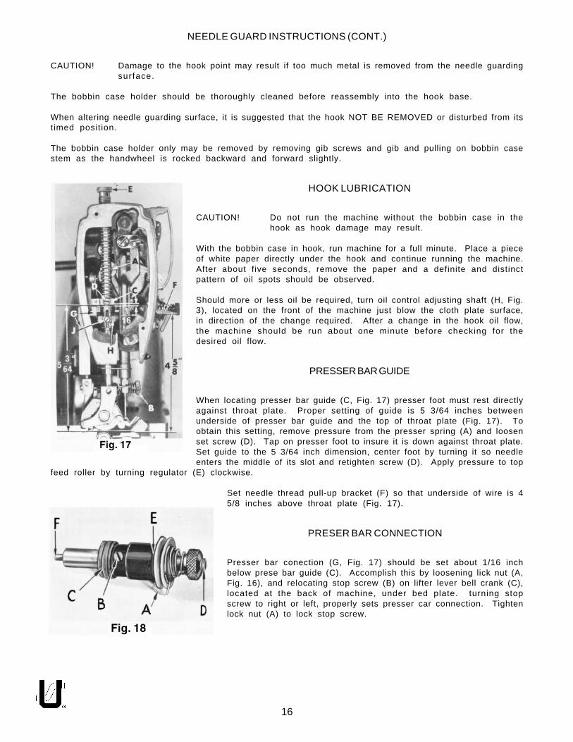
HOOK LUBRICATION
CAUTION! Do not run the machine without the bobbin case in thehook as hook damage may result.
With the bobbin case in hook, run machine for a full minute. Place a pieceof white paper directly under the hook and continue running the machine.After about five seconds, remove the paper and a definite and distinctpattern of oil spots should be observed.
Should more or less oil be required, turn oil control adjusting shaft (H, Fig.3), located on the front of the machine just blow the cloth plate surface,in direction of the change required. After a change in the hook oil flow,the machine should be run about one minute before checking for thedesired oil flow.
PRESSER BAR GUIDE
When locating presser bar guide (C, Fig. 17) presser foot must rest directlyagainst throat plate. Proper setting of guide is 5 3/64 inches betweenunderside of presser bar guide and the top of throat plate (Fig. 17). Toobtain this setting, remove pressure from the presser spring (A) and loosenset screw (D). Tap on presser foot to insure it is down against throat plate.Set guide to the 5 3/64 inch dimension, center foot by turning it so needleenters the middle of its slot and retighten screw (D). Apply pressure to top
feed roller by turning regulator (E) clockwise.
Set needle thread pull-up bracket (F) so that underside of wire is 45/8 inches above throat plate (Fig. 17).
PRESER BAR CONNECTION
Presser bar conection (G, Fig. 17) should be set about 1/16 inchbelow prese bar guide (C). Accomplish this by loosening lick nut (A,Fig. 16), and relocating stop screw (B) on lifter lever bell crank (C),located at the back of machine, under bed plate. turning stopscrew to right or left, properly sets presser car connection. Tightenlock nut (A) to lock stop screw.

17
TENSION ASSEMBLY ADJUSTMENT
Test check spring tension (A, Fig. 18). There should be enough tension toassure a good returning snap when the spring is depressed and released.Should it require adjusting, loosen set screw in head located under armand to the r ight of tension assembly and remove tension assembly.Partially loosen tension post set screw (B) in tension post socket (C). Turntension post (D) counterclockwise until check spring moves away fromupper stop (E) and has no tension on it. Turn tension post (D) in aclockwise direction until spring again touches upper stop (E). Proceedfurther in same direction approximately 1/4 turn until desired tension isobtained. When correctly set, tension post set screw (B) should be drawnup snugly, yet not forcefully. Further adjustment of check spring tensioncan be made by inserting a screwdriver into slotted end of tension post(D) and turning in required direction.
Replace tension assembly with check spring about 3/8 inch above thread take-up bracket (A, Fig. 19).Replace tension post assembly while presser foot is resting on throat plate.
TENSION RELEASE
Tension release should be set so as not release when sewing over seamsor when presser foot is raised. Adjustment of tension release cam (H, Fig.17) and in and out position of tension assembly are required for properopera t ion .
The in and out position of the tension assembly is correct when thetension discs are in line with the check spring eyelet (B, Fig. 19). Set thestop screw (C, Fig. 19) so that when the flange of the tension assemblyrests against it, this position is maintained. Tighten the tension assemblyset screw.
The tension release cam (H, Fig. 17) should now be posit ioned byloosening set screw (J) and then rising or lowering cam (H) to suit thesewing conditions. The average release point is between 1/4 and 5/16inch of presser foot lift above the throat plate. Tighten tension release cam set screw securely.
THREAD CONTROL
Check the adjustment of tension assembly (A, Fig. 20) andcheck spring tension. There should be enough tension to insurea good returning snap when spring (B, Fig. 20) is depressed andreleased. The check spring tension is adjusted from about 1 to1 1/4 ounces when measured with a postal scale, No. 21227DN,(C, Fig. 20). This is measured when the check is 1/32 to 1/16 inchfrom the stop. The tension post set screw should be drawn upsnugly but not forcefully tightened (B, Fig. 18). The tensionrelease pin should move freely in the tension post (D, Fig. 18).The check spring eyelet (B, Fig. 19), located just below thetension discs, should be set for correct height as follows:
With a thread running from the tension post to the thread take-up bracket (A, Fig. 19) in a straight line, the check spring eyeletshould be set 1/16 to 1/8 inch below the thread line (Fig. 19). Besure the eyelet is set close to the tension discs so that the checkspring will pass freely over it without obstruction. After making this setting, proceed to thread machine asper threading diagram (Fig. 3).

18
THREAD CONTROL (CONT.)
Sew slowly on a piece of material and observe the action of the check spring. The thread from the checkspring to the take-up bracket should be taut when the take-up is at the bottom if its stroke. Slight changesin needle thread tension may necessary at this point, but a reasonable tension should be used to maintaina uniform and consistent stitch. The machines are sewn off with 4 to 8 ounces maximum needle threadtension on T120 or similar thread, using a postal scale (A, Fig. 21). Depress check spring when checkingtension. The check spring will feel heavy to you, but this is a required setting for Class 63900, and as a result,the tension on the discs can be reduced.
BOTTOM COVER
Before removing bottom cover, place machine on bench so that the plug screw is accessible fromunderneath. Remove this plug screw and catch reservoir oil in some convenient container. Tip machineback, loosen and remove the two cover screws. Cover should be tapped free with a wooden block ormallet. Do not pry the cover loose with any sharp instrument as the gasket may become damaged.
CAUTION! When the bottom cover is removed, care should be taken not to mar or scratch the gasketseat area of the machine bottom.
Before replacing cover, the machine gasket seat should be wiped clean and free of all lint and dirt. Thecover gasket should also be inspected for damage and cleaned of dirt. Two additional gaskets are usedto seal the bolts and must be cleaned before assembly. Carefully set the cover in place and tighten the twobolts securely.
To replace a damaged cover gasket, proceed as follows:
1. Clean cover gasket recess of any foreign matter.
2. The gasket in cross section is triangular in shape with a groove in the top or widest part. With the coverresting as it does in the machine, oil distributing plate to your right, begin inserting in the middle of theback recess. The grooved wide edge of the gasket should be up and the ling sloped edge inward.Continue pressing the gasket into the cover recess until gasket is in place.
The bolt sealing gaskets may have a tendency to fall out when the cover is being installed and may betemporarily cemented in place by applying grease to their recesses. Torque to 72 inch lbs.
HOOK SHAFT
The hook shaft (A, Fig. 22) is held inposition by the pinion (B) and collar(C) thrusting against hard steel wash-ers (D) between the long left handbushing (E) and the short right handbushing (F).
Should hook shaf t set t ing be d is-turbed, the left and right position canbe determined by measuring from thehook end of the hook shaft to thepoint of a new needle (G) and read-ing 9/16 inch on a scale.

19
HOOK SHAFT (CONT.)
To reposition the hook shaft, loosen the set screws of the pinion and collar and establish the 9/16 inchdimension. Move the pinion and thrust washer against the left bushing, and after making certain one of theset screws in on the shaft FLAT, tighten both screws securely. Liberally coat the collar and its washer withoil and press the collar away from the pinion so as to remove all end play and tighten both set screwssecurely.
Hook oiling is accomplished by a high speed rotary pump on the end of the hook shaft. The quantity of oilsupplied to the hook is regulated by the longer or shorter path the oil is required to travel through themetering felt of metering cup (G, Fig. 23). (Increase or decrease of oil supply is controlled by a dial (P, Fig.23) with an arrow marked "INCREASE", found below the cloth plate.) The hook oil feed roller (A, Fig. 23) whichrests against the metering cup felt serves not only to feed oil to the unit from the oil reservoir, but filters theoil as well.
REMOVAL OF OILING DEVICE
The following steps are necessary to remove hook oiling device:
1. Remove hook oil feed roller (A, Fig. 23).
2. Remove hook oil control finger (B).
3. Apply finger pressure to hook oil control shaft (D) to prevent loss pump disc pivot pin (E); using Allenwrench, loosen set screw (C). Move assembly slowly to right, being careful not to drop pivot pinlocated on the end of the hook oil control shaft. When pivot pin is clear of pump disc (F), disc is freeto fall.
4. Remove metering cup (G) along with oil supply felt (K) and air seal felt (J).
5. Remove cop (H) from hook oil control shaft.

20
REASSEMBLY OF OILING DEVICE
Before reassembly, the end of the hook shaft, its spiral groove and the pump disc should be thoroughlycleaned. Remove any end play found in the hook shaft and determine that the 35/64 inch dimension hasbeen maintained (Fig. 22).
The following steps are necessary to reassemble the hook oiling device:
1. Remove and separate the air seal felt (J, fig. 23) from oil supply felt (K).
2. Make sure small end of air seal spring (R) is located on boss of metering cup behind felt attached tocup. Position the metering cup (G) and air seal spring on the hook shaft (S) with open end towardhandwheel end of the machine (Fig. 23).
NOTE: The hook shaft should pass through hole of felt attached to metering cup.
3. Position oil supply felt (K, Fig. 23) on the hook shaft, making certain the felt's projection extends intodovetail of metering cup.
4. Position air seal felt (J) on hook shaft.
5. Insert pump disc (F) into assembly tool No. 21227BY, with the stop pin on the spring side of tool, 180°from handle. Insert disc approximately half way into the spring and center in tool (Fig. 25).
6. Insert hook oil control shaft (D, fig. 23) and its bushing (L) part way into its boss which is located directlybehind the hook shaft, being careful NOT TO DROP the pump disc pivot pin (E).

21
REASSEMBLY OF OILING DEVICE (CONT.)
7. A clearance cut on the edge of the metering cup, located between the dovetai l and the longhorizontal slot, has been provided for the pump disc tool and should be facing you (Fig. 25).
8. With the fork of the tool in line with the meter-ing cup clearance cut and centered aboutthe hook shaft end, press felts to the left withtool until the pump disc is in contact with endof the hook shaft.
9. Press hook oil control shaft bushing (L) to theleft until control shaft (D) is approximately 1/16 inch away from pump disc (F). Make surethe control shaft pivot pin (E) seats in thedepression at the center of the pump disc.Tighten set screw (C, Fig. 25) and withdrawassembly tool. Be sure sir seal felt (J) hasseated against the pump disc.
10. Turn the hook oil control shaft (D, Fig. 26) untilscrew hole (M) is accessible. Manually rotatepump disc (F) so its stop pin (N) is 90° above screw hole.
11. Rotate metering cup so the short slot (T) is 180° from stop pin (N). Now, install hook oil control finger(B) by first hanging the hooked portion of finger over the stop pin and lowering to insert the projectionat bottom left into the short slot of the metering cup. Tighten the finger in place by means of screwand washer, making sure the hook oil control fingerdoes not bind or distort metering cup.
12. Assemble the hook oil feed roller (A, Fig. 27), androtate the metering cup so that the roller contactsthe metering cup felt at point (U, Fig. 27). Turn theoil control adjusting shaft (P, Fig. 27) in the increasedirection until projection stops against the stop in(this is maximum oil supply) and install the cog (H,Fig. 27) on the hook oil control shaft. After meshingthe teeth, tighten set screw securely.
13. Check for proper contact of the hook oil feed rollerand the metering cup by turning the oi l controladjusting shaft through its complete travel and ob-serve the feed roller turning as the metering cupturns. With the oil control adjusting shaft set atmaximum, the feed roller point of contact with themetering cup felt should be at the mid-point of theslot that permits the metering cup felt to enter themeter ing cup.
NOTE: The feed roller should be in contact with the metering cup felt through its complete travel.
UPPER MAIN SHAFT
In a high speed machine, the alignment of the take-up mechanism is extremely important and is controlledby the left and right position of the upper main shaft. Should the main shaft position be altered, it isimperative that the take-up alignment be checked before operating.
22
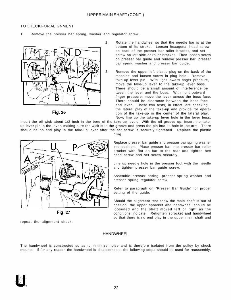
UPPER MAIN SHAFT (CONT.)
TO CHECK FOR ALIGNMENT
1. Remove the presser bar spring, washer and regulator screw.
2. Rotate the handwheel so that the needle bar is at thebottom of its stroke. Loosen hexagonal head screwon back of the presser bar roller bracket, and setscrew on left side or roller bracket. Then loosen screwon presser bar guide and remove presser bar, presserbar spring washer and presser bar guide.
3. Remove the upper left plastic plug on the back of themachine and loosen screw in plug hole. Removetake-up lever pin. With light inward finger pressure,move the take-up lever to the take-up lever boss.There should be a small amount of interference between the lever and the boss. With light outwardfinger pressure, move the lever across the boss face.There should be clearance between the boss faceand lever. These two tests, in effect, are checkingthe lateral play of the take-up and provide for opera-tion of the take-up in the center of the lateral play.Now, line up the take-up lever hole in the lever boss.
Insert the oil wick about 1/2 inch in the bore of the take-up lever. With the oil groove up, insert the take-up lever pin in the lever, making sure the wick is in the groove and press the pin into its hole in the arm. Thereshould be no end play in the take-up lever after the set screw is securely tightened. Replace the plastic
p lug .
Replace presser bar guide and presser bar spring washerinto position. Place presser bar into presser bar rollerbracket with flat on bar to the rear and tighten hexhead screw and set screw securely.
Line up needle hole in the presser foot with the needleand tighten presser bar guide screw.
Assemble presser spring, presser spring washer andpresser spring regulator screw.
Refer to paragraph on "Presser Bar Guide" for propersetting of the guide.
Should the alignment test show the main shaft is out ofposition, the upper sprocket and handwheel should beloosened and the shaft moved lef t or r ight as theconditions indicate. Retighten sprocket and handwheelso that there is no end play in the upper main shaft and
repeat the al ignment check.
HANDWHEEL
The handwheel is constructed so as to minimize noise and is therefore isolated from the pulley by shockmounts. If for any reason the handwheel is disassembled, the following steps should be used for reassembly.

23
HANDWHEEL (CONT.)
1. Using the upper main shaft as a mandrel, assemble the pulley thrust face down so that at least 1 1/2inches of the shaft protrudes above it. Tighten the two set screws.
2. Place the rubber isolator ring on the pulley face and align holes.
3. Carefully slide handwheel down the shaft to contact the isolator and align the three holes.
4. Three plastic "O" rings are now inserted into their respective holes in the handwheel.
5. The outer isolator rings and cap are assembled.
6. Insert the three screws that are run through the complete assembly and tighten lightly.
7. Loosen the two pulley screws and slowly revolve the whole assembly several times for good alignment.Now, gradually tighten the three screws, moving from one to the other until all are snug.
8. The assembly should run true as it revolves freely on the shaft. If any sidewise run-out is noted, it canbe corrected by slight changes of screw pressure in the three isolator screws.
CAUTION! When replacing the handwheel assembly on the main shaft, care must be taken not todamage the oil seal located near the end of the shaft. The surface of the ring should be lightly oiledand the handwheel worked over the seal gently.
ATTACHMENTS
Style 63900AM, AML is equipped with a retractable hemmer (A, Fig. 28) which produces 3/8 to 1/2 inch widthof hem. To adjust to desired width loosen two screws (B & C) and slide hemmer scroll (D) to the right or left.
To change the sewing margin loosen screws (E & F) and slidethe hemmer (A) to the right or left to obtain desired margin.
Style 63900AT is equipped with an adjustable edge guide forproducing margins from 1/2 to 2 1/2 inches wide. For marginswider than 1 5/16 inches the base of the edge guide must bereversed.
To change margin relocate edge guide in holes provideduntil desired margin is obtained.
Style 63900AAE, AW is equipped with a cloth plate extensionto provide a platform for guiding trousers. It is easily attachedto the machine by three No. 22517B screws.
NEEDLE HOLE INSERT(SEE PAGE 44)
The throat plate has a replaceable needle hole insert. To remove this insert, drive it out from the undersideof the throat plate.

24

Part No. Descript ionAmt .Req.
Ref.No.
25
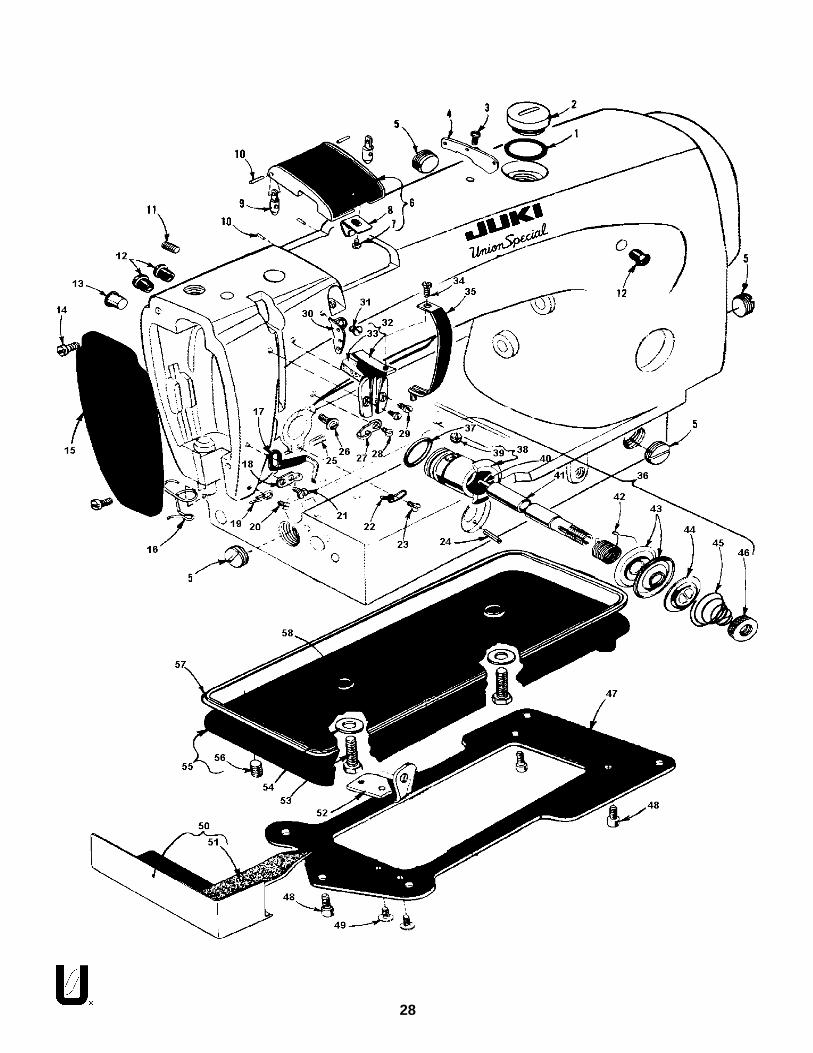
MAINFRAME, BUSHING, OIL GAUGE HEAD OIL SIPHON ANDMISCELLANEOUS OILING PARTS
1.2.3.4.5.6.7.8.9.
10.11.12.13.14.15.16.17.18.19.20.21.22.23.24.25.26.27.28.29.30.31.
32. thru 60. see following page.
61490B61490C63949R22569B666-200666-25463993D666-22563984C666-22363993C22784K61494N63494M56393AA22815666-224666-22861985H61985G61494L63994666-21463953A2256463957A51-159BLK61490D63494C61494D61494E
Main Shaft Bushing Housing, including bushing ...........................................Bushing ..................................................................................................
Plug, for bed .................................................................................................Screw ...........................................................................................................Oil Felt ..........................................................................................................Felt Baffle .....................................................................................................Head Oil Supply Line ....................................................................................Felt ...............................................................................................................Spring Clip ....................................................................................................Roll Felt .........................................................................................................Head Oiler Assembly ...................................................................................Screw ...........................................................................................................Retaining Grommet .....................................................................................Oil Siphon Connecting Tube ........................................................................
Oil Tube ..................................................................................................Plug Screw ....................................................................................................Roll Felt .........................................................................................................Oil Felt ..........................................................................................................Needle Bar Frame Rocker Shaft Bushing, right .............................................Needle Bar Frame Rocker Shaft Bushing, left ................................................Stud ..............................................................................................................Oil Siphon Head Tube ...................................................................................
Oil Felt ....................................................................................................Oil Shield ......................................................................................................Screw ...........................................................................................................Presser Bar Bushing, lower ............................................................................Plug ..............................................................................................................Upper Main Shaft Bushing, left ......................................................................Oil Gauge Float Assembly ............................................................................
Oil Gauge Float ......................................................................................Oil Gauge Float Lever ............................................................................
1114111111121121111111111111111

26

Part No. Descript ionAmt .Req.
Ref.No.
27
32.33.34.35.36.37.38.39.40.41.42.43.44.45.46.47.48.49.50.51.52.53.54.55.56.57.58.59.60.
-
1. thru 31. see preceding page.
MAINFRAME, BUSHING, OIL GAUGE HEAD OIL SIPHON ANDMISCELLANEOUS OILING PARTS (CONT.)
22890C2256463993H63962D63962G666-23861293N63494D666-237666-22163962E63962F63962C63494K63494F63494G660-45561432B61494H660-22111635B61494T61496P61496S61441A63432C63993B666-239666-23463490B
Screw .........................................................................................................Screw ..........................................................................................................Oil Siphon Primer Position Bracket ..............................................................Lower Reduction Gear Shaft Bushing, left ..................................................Upper Reduction Gear Shaft Bushing, left .................................................Bed Oil Drain Hole Felt ................................................................................Bed Plug .....................................................................................................Oil Siphon Priming Cup .............................................................................
Cup Felt ................................................................................................Oil Wick, for bushing housing .....................................................................Middle Reduction Gear Stud Bushing ........................................................Upper Reduction Gear Shaft Bushing, right ...............................................Lower Reduction Gear Shaft Bushing, right ...............................................Oil Gauge Assembly ..................................................................................
Nut ........................................................................................................Spring Washer ......................................................................................"O" Ring ................................................................................................
Hook Drive Shaft Bushing, right ..................................................................Oil Gauge Connecting Link ........................................................................"O" Ring ......................................................................................................Nut .............................................................................................................Float Lever Pivot Stud .................................................................................Hook Oil Control Shaft Bushing ...................................................................Hook Oiling Control Adjusting Bushing .......................................................Hook Shaft Bushing, right ............................................................................Hook Drive Shaft Bushing, left ....................................................................Hook Shaft Bushing Oil Tube .......................................................................Oil Wick .......................................................................................................Head Oil Attraction Felt .............................................................................Gasket (not shown) ...................................................................................
111111111111111111111111111111
28
Part No. Descript ionAmt .Req.
Ref.No.
29
MAIN FRAME MISCELLANEOUS COVERS AND NEEDLE TENSION PARTS
1.2.3.4.5.6.7.8.9.
10.11.12.13.14.15.16.17.18.19.20.21.22.23.24.25.26.27.28.
63494A22733D22570A61470D22539P63982A22513D63982F61982C61982D22894E63994C660-409225166398263970B63970A63470A63470902276663492HS24C660-219A22597E22863B61470C22766
Gasket .......................................................................................................Plug Screw, for oil filler hole .....................................................................Screw ..........................................................................................................Frame Thread Eyelet ...................................................................................Plug Screw ..................................................................................................Top Cover ....................................................................................................
Screw ....................................................................................................Spring Clip .............................................................................................
Top Cover Hinge .......................................................................................Top Cover Hinge Pin .................................................................................Screw .........................................................................................................Plug, plastic, overall length 7/16 inch (11.1mm) ..........................................Tension Release Bushing Plug ......................................................................Screw ...........................................................................................................Head Cover .................................................................................................Needle Bar Bushing Thread Guide ..............................................................Thread Pull-up Bracket ................................................................................Upper Needle Thread Eyelet .....................................................................Lower Needle Thread Eyelet .......................................................................Screw ..........................................................................................................Screw ..........................................................................................................Tension Post Eyelet .......................................................................................Screw ..........................................................................................................Roll Pin .........................................................................................................Set Screw, for tension assembly ..................................................................Stop Screw, for tension assembly .............................................................Thread Guide ..........................................................................................Screw ......................................................................................................
1111411124161211111111111111
29. thru 58. see following page.

30

Part No. Descript ionAmt .Req.
Ref.No.
31
MAIN FRAME MISCELLANEOUS COVERS AND NEEDLE TENSION PARTS (CONT.)
29.30.31.32.33.34.35.36.37.38.39.40.41.42.43.44.45.46.47.48.49.50.51.52.53.54.55.56.57.58.
1. thru 28. see preceding page.
2256261471A2280563971A666-222225646345129475AR660-269A61492E22560G61492G61492F6345310961492H61392F1461292C21680AX22652D822517B63996666-24021662AE22644K48652-1663982C22571F61482J660-204
Screw ...........................................................................................................Frame Thread Eyelet ....................................................................................Screw ...........................................................................................................Take-up Lever Shield ..................................................................................
Felt Pad ................................................................................................Screw ..........................................................................................................Take-up Shield ..........................................................................................Thread Tension Assembly ............................................................................
Quad Ring .............................................................................................Tension Post Socket ............................................................................
Set Screw .........................................................................................Tension Release Pin ................................................................................Tension Post ........................................................................................Take-up Spring ...................................................................................Tension Disc .........................................................................................Tension Release Washer ........................................................................Tension Spring ........................................................................................Tension Nut ............................................................................................
Base Plate ....................................................................................................Screw, for base plate ...................................................................................Screw ...........................................................................................................Hook Oil Return Channel .............................................................................
Hook Oil Return Channel Felt .................................................................Shaft Bracket, rear .....................................................................................Screw ........................................................................................................Washer ......................................................................................................Oil Reservoir Bottom Cover .......................................................................
Plug Screw .............................................................................................Gasket ........................................................................................................."O" Ring .......................................................................................................
211111111111112111132111221112

32

Part No. Descript ionAmt .Req.
Ref.No.
33
MAIN AND HOOK DRIVE SHAFTS, NEEDLE BAR AND FOOT LIFTER MECHANISM
1.2.3.4.5.6.7.8.9.
10.11.12.13.14.15.16.17.18.19.20.21.22.23.24.25.26.27.28.29.30.31.32.33.34.35.36.37.38.39.40.41.42.
--
43.44.45.46.47.48.49.50.51.52.53.54.55.
63917C6344322894C6394063993G61360G2288461460A22653D661460B660-2696392161421G22574C63921BA22894V652B2061468B421H22890A634666146722758B15872F22817A660-283A61468D63479E22651CD-36146022884993722874F6342263491D2283922894W22894V29486AB6145161451G61451D-62561541D-62661541D-6276145522757D6345563952C61451A61351C22784E6125522562B61451B61468F61468E22712G
Needle Bar, marked "EN" ......................................................................................................Hook Shaft Driving Gear ......................................................................................................
Set Screw ....................................................................................................................Hook Driving Shaft .............................................................................................................Oil Return Pump ................................................................................................................Shaft Collar .........................................................................................................................
Screw .................................................................................................................................Hook Driving Shaft Sprocket ..............................................................................................
Screw ...............................................................................................................................Feed Driving Belt ...................................................................................................................Quad Ring ..............................................................................................................................Handwheel Assembly ...........................................................................................................
Hub Washer .....................................................................................................................Screw ...............................................................................................................................Handwheel ...................................................................................................................Set Screw ........................................................................................................................
Lock Washer .............................................................................................................................Lifter Lever Extension Stud and "S" Hook ................................................................................Lifter Lever Chain ......................................................................................................................Screw, left thread ....................................................................................................................Lifter Lever .................................................................................................................................Lifter Lever Link ......................................................................................................................Screw .........................................................................................................................................Lifter Lever Spring .....................................................................................................................Screw .........................................................................................................................................Spring Grip Fastener ..............................................................................................................Chain Hook ..............................................................................................................................Main Shaft Reduction Drive Gear ......................................................................................
Set Screw .........................................................................................................................Main Shaft Driving Sprocket ...................................................................................................
Set Screw ...........................................................................................................................Nut ..........................................................................................................................................Screw .......................................................................................................................................Main Shaft ................................................................................................................................Counterweight .......................................................................................................................Screw .........................................................................................................................................Spot Screw ...............................................................................................................................Set Screw ...................................................................................................................................Take-Up Lever and Needle Bar Link Assembly ..............................................................
Take-Up Lever ..............................................................................................................Take-Up Lever Eyelet .........................................................................................
Needle Bearing, .625 inch diameter .........................................................................Needle Bearing, .626 inch diameter ..........................................................................Needle Bearing, .627 inch diameter ..........................................................................Needle Bar Link .............................................................................................................Screw .............................................................................................................................Thrust Washer ...................................................................................................................Take-Up Lever Crank Pin, marked "L" .........................................................................Take-Up Lever Link .......................................................................................................Thrust Washer ...................................................................................................................Screw ..............................................................................................................................
Needle Bar Connection ........................................................................................................Screw ..............................................................................................................................
Take-Up Lever Pin .................................................................................................................Lifter Lever Bell Crank ..........................................................................................................Bell Crank Roller ....................................................................................................................Screw ....................................................................................................................................
11211121211113121111111111112121111212111
3838381111111111111

34

Part No. Descript ionAmt .Req.
Ref.No.
35
NEEDLE FEED DRIVING PARTS
1.2.3.4.5.6.7.8.9.
10.11.12.13.14.15.16.17.18.19.20.21.22.
22894E61985J666-13961985A63985B22504H61985D61985A5177388B61984C61985F2283960038G666-173201829126EL22894J63984A9514077
Screw, for needle bar frame pivot stud ........................................................Needle Bar Frame Pivot Adjustable Bushing ................................................Oil Wick ........................................................................................................Needle Bar Frame Pivot Stud ........................................................................Needle Bar Frame ........................................................................................Screw ...........................................................................................................Needle Bar Frame Rock Shaft Connecting Link ............................................Needle Bar Frame Rock Shaft .......................................................................Collar ...........................................................................................................
Screw .....................................................................................................Needle Bar Drive Eccentric Connecting Stud ..............................................Needle Bar Frame Rock Shaft Driving Lever .................................................
Clamp Screw .........................................................................................Bearing ........................................................................................................Oil Wick ........................................................................................................Washer .........................................................................................................Nut ...............................................................................................................Needle Feed Drive Eccentric and Connecting Rod Assembly .....................
Set Screw ...............................................................................................Needle Bearing Retaining Collar .................................................................
Screw .....................................................................................................Nut ...............................................................................................................
1111121111111111112123

36

Part No. Descript ionAmt .Req.
Ref.No.
37
PRESSER FEET, PRESSER BAR, TOP FEED ROLLER MECHANISM AND ATTACHMENTS
1.2.3.4.5.6.7.8.9.
10.11.12.13.14.15.16.17.18.19.20.21.22.23.24.25.26.27.28.29.30.31.32.33.
*33A.34.35.
6392022585A27-435BLK61458H21756G61439AN22738B952288261458D2284561458C88B23063959B73C225706135661256G61257G63457R63958660-219B61458G6395761439AM54430E660-24963939K110-451292C13863939R61439AG9561439AP
Presser Foot, marked "AF", for Style 63900AW ...............................................Screw ...........................................................................................................Washer .........................................................................................................Presser Foot Shank .......................................................................................Screw Pin ......................................................................................................Presser Foot Shank Hinge Pin ........................................................................Screw ...........................................................................................................Set Screw, for presser bar .............................................................................Screw, for presser bar ...................................................................................Presser Foot Tension Bar ...............................................................................
Screw Pin ................................................................................................Presser Foot Lifter Block ................................................................................
Screw .....................................................................................................Screw ...........................................................................................................Presser Bar Guide .........................................................................................
Screw .....................................................................................................Screw .....................................................................................................
Roller Presser Spring .................................................................................Presser Spring Washer ..............................................................................Presser Spring Regulator and Bushing ......................................................Presser Bar Spring Washer .......................................................................Presser Bar Connection ...........................................................................
Roll Pin ...............................................................................................Tension Release Cam ..................................................................................Presser Bar ...................................................................................................Top Roller Bracket ........................................................................................
Pin ..........................................................................................................Needle Bearing ...................................................................................
Top Feed Roller Shaft ....................................................................................Presser Foot Tension Regulating Spring ........................................................Presser Foot Tension Regulating Nut .............................................................Screw ...........................................................................................................Top Feed Roller, 48 teeth, 1 1/4 inch diameter ............................................Top Feed Roller, coarse knurl, 1 1/4 inch diameter .......................................
Set Screw ...............................................................................................Upper Roller Stripper ....................................................................................
114111211111111111111111111211121121
36. thru 69. see following page.
* Available if specified on order or as an extra send and charge item.

38

Part No. Descript ionAmt .Req.
Ref.No.
39
36.37.38.39.
39A.40.41.42.43.44.45.46.47.48.49.50.
50A.51.52.53.
54.55.56.57.58.59.60.61.62.63.64.65.66.67.68.69.
PRESSER FEET, PRESSER BAR, TOP FEED ROLLER MECHANISM AND ATTACHMENTS
1. thru 35. see preceding page.
22798A61430V2162961430CL61430BW22738F61430BX6390322875614032270463930A63920A73A61430R63920B3/863920B1/222738B61430X23564
69588823564E23564D2271123564A23364AD23364AG2259391A23564C907201102271123564G22517B
Screw, for Styles 63900AW, AEE ....................................................................Spring, for edge guide, for Styles 63900AW, AEE ...........................................Screw, for compensating edge guide, ........................................................Edge Guide, for Style 63900AEE ....................................................................Compensating Edge Guide, for Style 63900AW ...........................................
Screw .....................................................................................................Compensating Edge Guide ...................................................................
Edge Guide Mounting Bracket, for Style 63900AT ........................................Screw, for edge guide mounting bracket ....................................................Edge Guide, for Style 63900AT ......................................................................Screw ...........................................................................................................Presser Foot Bottom, for Style 63900AAE .......................................................Presser Foot, for Style 63900AT ......................................................................
Screw .....................................................................................................Presser Foot Edge Guide ........................................................................
Presser Foot, for 3/8 inch hem, on Style 63900AM .........................................Presser Foot, for 1/2 inch hem, on Style 63900AM .........................................
Screw .....................................................................................................Presser Foot Needle Guard, marked "A" .............................................
Hemmer, complete, for making 3/8 to 1/2 inch turned don hem, on Style63900AM ......................................................................................................
Collar .....................................................................................................Set Screw .........................................................................................
Hemmer Operating Rod ........................................................................Hemmer Base ........................................................................................Screw .....................................................................................................Hemmer Scroll, right ..............................................................................Hemmer Scroll, left ................................................................................Hemmer Scroll Slide Spring ....................................................................Screw .....................................................................................................Stop Screw .............................................................................................Hemmer Scroll Slide ...............................................................................Nut .........................................................................................................Hemmer Operating Rod Spring ..............................................................
Screw, for hemmer, on Style 63900AM .........................................................Hemmer Mounting Bracket ..........................................................................Screw ...........................................................................................................
1111121121111111111
11111211121111212

40
Part No. Descript ionAmt .Req.
Ref.No.
41
ROTATING HOOK ASSEMBLY AND HOOK OILING PARTS
1.--
2.3.4.5.6.7.8.9.
10.11.12.13.14.15.16.17.
-18.19.20.21.22.23.24.25.26.27.28.29.30.31.32.33.34.35.36.37.38.39.40.41.42.43.44.45.46.47.48.49.50.51.52.
29474SA29474AH29474VA63913A61415A6121661216N22564M22716K61414F63918A6141561212B63914D63907A61411B22716M22569H639086340861210C22716L61351C128658861444896144063432HA73B61496V22868D51225W61496F61496G61496E63496B61496J666-181666-18261496C660-219D61496D35857R61496L61496K27-527BLK2281961496P22894R61496N660-22139198D61496M22743
Rotating Hook Assembly for 63900AAE, AT, AW ............................................Rotating Hook, for Style 63900AML, 1/2, 3/8, AMLZ .......................................Rotating Hook, for Style 63900AM, 1/2, 3/8 ................................................
Bobbin Case Assembly ..........................................................................Bobbin Case Latch Lever .................................................................Bobbin Case Latch Hinge Pin ...........................................................Bobbin Case Latch Spring ................................................................Screw ...............................................................................................Tension Regulating Screw ................................................................Bobbin Case Tension Spring .............................................................Bobbin Case ....................................................................................Bobbin Case Latch ...........................................................................
Bobbin ....................................................................................................Bobbin Case Holder ...............................................................................Hook, Thread Retainer and Thread Deflector Assembly .........................
Hook Thread Retainer ......................................................................Screw ...............................................................................................Set Screw .........................................................................................Hook ................................................................................................Hook, for Styles 63900AML1/2, 3/8 ...................................................Hook Thread Deflector .....................................................................Screw ...............................................................................................
Thrust Washer ................................................................................................Thrust Collar ................................................................................................
Screw .....................................................................................................Hook Shaft Pinion ..........................................................................................
Screw .....................................................................................................Hook Shaft ....................................................................................................Hook Shaft Collar, left ...................................................................................
Screw .....................................................................................................Hook Shaft Wick Insert Assembly ..................................................................Screw ...........................................................................................................Washer .........................................................................................................Retaining Spring ...........................................................................................Pivot Pin ........................................................................................................Hook Oil Feed Roller .....................................................................................Metering Cup ...............................................................................................Air Seal Spring ...............................................................................................Oil Supply Felt .............................................................................................Air Seal Felt ...................................................................................................Pump Disc .....................................................................................................
Roll Pin ....................................................................................................Pump Disc Pivot Pin ...................................................................................Spring ...........................................................................................................Hook Oil Control Shaft ...................................................................................Hook Oil Control Finger .................................................................................Washer ........................................................................................................Screw ............................................................................................................Hook Oil Control Shaft Bushing .....................................................................Spot Screw ....................................................................................................Oil Control Adjusting Shaft ............................................................................Oil Seal Ring ..................................................................................................Spring Washer ...............................................................................................Oil Control Cog .............................................................................................
Set Screw ................................................................................................
1111111211111111321114212121121111111111111111111111121

42

Part No. Descript ionAmt .Req.
Ref.No.
43
FEED ROLLER DRIVING PARTS
1.2.3.4.5.6.7.8.9.
10.11.12.13.14.15.16.17.
*18.*-
19.*20.
*-21.22.23.24.25.26.27.28.29.
63962H22894V39552C660-318660-20763962L63962K2287863962J22525C22894J63962B22597A63962A6396261248H53163949-3963949-3718-50063949-4163949-4318-5006393963939H22652B-1063939A61339D9563982E22517B
Lower Reduction Gear .................................................................................Set Screw ...............................................................................................
Thrust Washer ...............................................................................................Truarc Ring ..................................................................................................."O" Ring ........................................................................................................Middle Reduction Gear .............................................................................Upper Reduction Drive Dear ........................................................................
Set Screw ...............................................................................................Upper Reduction Driven Gear ......................................................................
Screw .....................................................................................................Set Screw ...............................................................................................
Upper Reduction Gear Shaft ........................................................................Set Screw ......................................................................................................Middle Reduction Gear Stud ........................................................................Lower Reduction Gear Shaft ........................................................................Thrust Collar .................................................................................................
Screw .....................................................................................................Upper Stitch Regulating Gear, for Styles 63900M, T .......................................Upper Stitch Regulating Gear, for Styles 63900W, AE ....................................
Set Screw ...............................................................................................Lower Stitch Regulating Gear, for Styles 63900M, T .......................................Lower Stitch Regulating Gear, for Styles 63900W, AE ....................................
Set Screw ...............................................................................................Top Feed Roller Drive Shaft Bushing Housing ................................................
Top Feed Roller Drive Shaft Bushing ........................................................Screw ...........................................................................................................Top Feed Roller Drive Shaft ...........................................................................Lower Feed Roller Drive Gear .......................................................................
Set Screw ...............................................................................................Cloth Plate Extension, for Style 63900W, AE ..................................................Screw, for Style 63900W, AE ..........................................................................
30. thru 52. see following page.
* See page 13 "Gear Chart", for the gear combinations to produce stitches per inch, otherthan the ones indicated.
† Available as extra send and charge item.
1222111213211111211111111211213
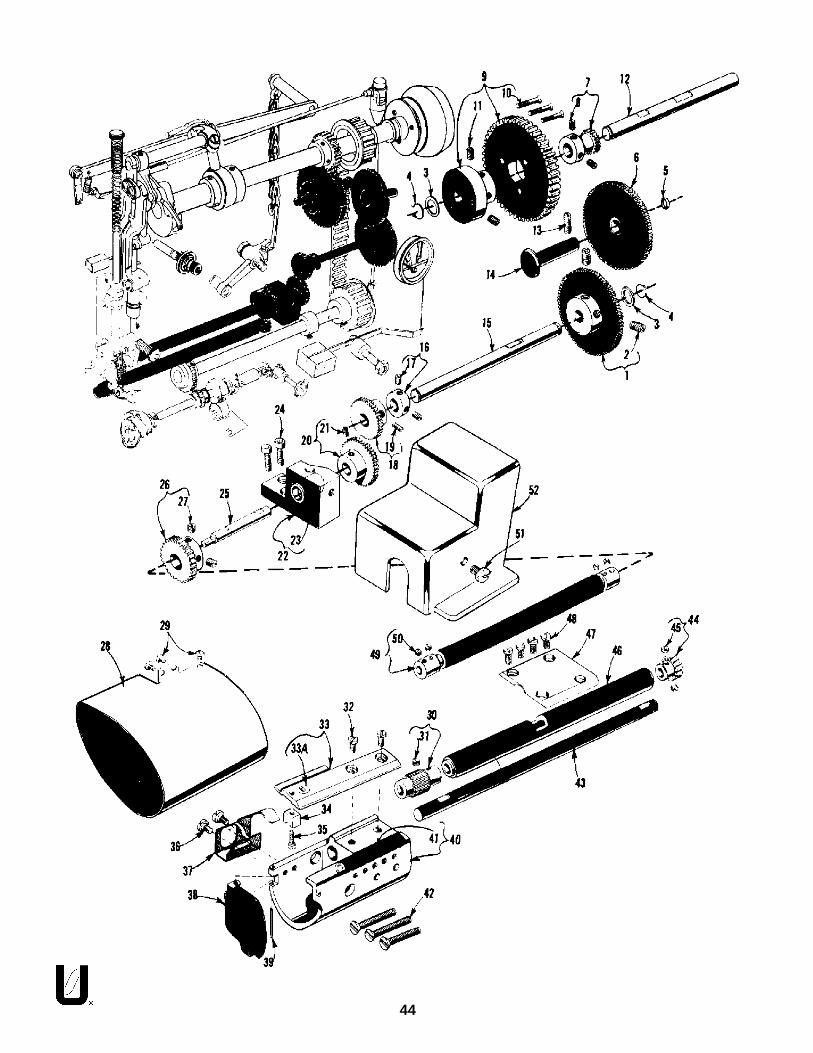
44

Part No. Descript ionAmt .Req.
Ref.No.
45
30.†-
31.32.33.
33A.34.35.36.37.38.39.40.41.42.43.44.45.46.47.48.49.50.51.52.
63939P63939E2258022569C6392863928A61414E22653K-62287563939N63982B660-2196394163941A22637R-9663939B51239E2258063939S63939F22569C63939J22650AA-222517B63982D
Lower Feed Roller, 24 teeth ..........................................................................Lower Feed Roller, medium diamond knurl ..................................................
Set Screw ...............................................................................................Screw ...........................................................................................................Throat Plate ..................................................................................................
Needle Hole Insert, .080 inch dia. needle hole .......................................Bobbin Case Holder Positioning Finger ........................................................Screw ...........................................................................................................Screw ...........................................................................................................Lower Feed Roller Stripper ............................................................................Hook Housing Cover, for Styles 63900M, T .....................................................Roll Pin, for Styles 63900M, T ..........................................................................Hook Shaft Bushing Housing .........................................................................
Hook Shaft Bushing ................................................................................Screw ...........................................................................................................Lower Feed Roller Drive Shaft .......................................................................Lower Feed Roller Driven Gear .....................................................................
Set Screw ...............................................................................................Lower Feed Drive Shaft Housing ...................................................................Clamp Plate .................................................................................................Screw ...........................................................................................................Top Feed Roller Flexible Drive Shaft ..............................................................Allen Set Screw, standard No. 8-32 national coarse thread, 1/8 inch long ...........Screw ...........................................................................................................Feed Drive Gear Cover ................................................................................
FEED ROLLER DRIVING PARTS (CONT.)
1. thru 29. see preceding page.
† Available as extra send and charge item.
1112111121111131121141411

46

Part No. Descript ionAmt .Req.
Ref.No.
47
BOBBIN WINDER AND MISCELLANEOUS ACCESSORIES
1.2.3.
*4.5.
*6.7.
*8.9.
10.11.12.
13.#14.
--
61477M22846M-1261337N21227BY6121221388AV22653E-2021227BZ22789B21665L21663F21665C
21663C650AC-3628604S660-457
Bobbin Winder, complete ............................................................................Wood Screw ..........................................................................................Trip Latch ...............................................................................................
Felt Assembly Adaptor .................................................................................Bobbin ..........................................................................................................Bearing Housing Puller .................................................................................
Clamp Screw .........................................................................................Take-Up Eyelet Replacement Tool ...............................................................
Thumb Screw .........................................................................................Bell Crank Actuator Rod, for Styles 63900T, W, and AE ..................................Knee Press Plate Rod, for Style 63900M .........................................................Rock Shaft Connecting Arm, for actuating folder actuator finger, forStyle 63900M ...............................................................................................Knee Press Plate Rod, for Styles 63900T, W, and AE .......................................Screw, for table top ......................................................................................Can of Oil, Spec. No. 175, 1 quart (not shown) ..............................................Dust Cover, (not shown) ...............................................................................
12111111111
11411
* Not furnished with machine, but may be ordered separately as an extra send and charge.
# Not furnished with machine, but is a component of 1400D pedestal.

NUMERICAL INDEX OF PARTS
48
2 2 7 1 6 L . . . . . 4 12 2 7 1 6 M . . . . . 4 12 2 7 3 3 D . . . . . 2 922738B .....37, 392 2 7 3 8 F . . . . . 3 92 2 7 4 3 . . . . . 4 12 2 7 5 7 D . . . . . 3 32 2 7 5 8 B . . . . . 3 32 2 7 6 6 . . . . . 2 92 2 7 8 4 E . . . . . 3 32 2 7 8 4 K . . . . . 2 52 2 7 8 9 B . . . . . 4 72 2 7 9 8 A . . . . . 3 92 2 8 0 5 . . . . . 3 12 2 8 1 5 . . . . . 2 52 2 8 1 7 A . . . . . 3 32 2 8 1 9 . . . . . 4 122839 .....33, 352 2 8 4 5 . . . . . 3 722846M-12 .....472 2 8 6 3 B . . . . . 2 92 2 8 6 8 D . . . . . 4 12 2 8 7 4 F . . . . . 3 322875 .....39, 452 2 8 7 8 . . . . . 4 32 2 8 8 2 . . . . . 3 72 2 8 8 4 . . . . . 3 32 2 8 9 0 A . . . . . 3 32 2 8 9 0 C . . . . . 2 72 2 8 9 4 C . . . . . 3 322894E .....29, 3522894J .....35, 432 2 8 9 4 R . . . . . 4 122894V .....33, 432 2 8 9 4 W . . . . .3 32 3 0 . . . . . 3 723364AD ... . .3923364AG .... .392 3 5 6 4 . . . . . 3 92 3 5 6 4 A . . . . . 3 92 3 5 6 4 C . . . . . 3 92 3 5 6 4 D . . . . . 3 92 3 5 6 4 E . . . . . 3 92 3 5 6 4 G . . . . . 3 927-435BLK .....3727-527BLK .....412 8 6 0 4 S . . . . . 4 729126EL . . . . .3529474AH ... . .4129474SA .. . . .4129474VA .. . . .4129475AR ... . .3129486AB .. . . .333 5 8 5 7 R . . . . . 4 13 9 1 9 8 D . . . . . 4 13 9 5 5 2 C . . . . . 4 34 2 1 H . . . . . 3 351-159BLK .....255 1 2 2 5 W . . . . .4 1
1 0 9 . . . . . 3 11 1 0 - 4 . . . . . 3 71 1 6 3 5 B . . . . . 2 71 2 8 6 5 . . . . . 4 11 3 8 . . . . . 3 71 4 0 7 7 . . . . . 3 51 5 8 7 2 F . . . . . 3 31 8 . . . . . 3 51 8 - 5 0 0 . . . . . 4 32 0 . . . . . 3 52 0 1 1 0 . . . . . 3 921227BY .. . . .4721227BZ . . . . .4721388AV .. . . .472 1 6 2 9 . . . . . 3 921662AE .. . . .312 1 6 6 3 C . . . . . 4 72 1 6 6 3 F . . . . . 4 72 1 6 6 5 C . . . . . 4 72 1 6 6 5 L . . . . . 4 721680AX .. . . .312 1 7 5 6 G . . . . . 3 72 2 5 0 4 H . . . . . 3 52 2 5 1 3 D . . . . . 2 92 2 5 1 6 . . . . . 2 922517B .....31, 39,22517B .....43, 452 2 5 2 5 C . . . . . 4 32 2 5 3 9 P . . . . . 2 92 2 5 6 0 G . . . . . 3 12 2 5 6 2 . . . . . 3 12 2 5 6 2 B . . . . . 3 322564 .....25, 27, 312 2 5 6 4 M . . . . . 4 12 2 5 6 9 B . . . . . 2 52 2 5 6 9 C . . . . . 4 52 2 5 6 9 H . . . . . 4 12 2 5 7 0 . . . . . 3 72 2 5 7 0 A . . . . . 2 92 2 5 7 1 F . . . . . 3 12 2 5 7 4 C . . . . . 3 32 2 5 8 0 . . . . . 4 52 2 5 8 5 A . . . . . 3 72 2 5 9 3 . . . . . 3 92 2 5 9 7 A . . . . . 4 32 2 5 9 7 E . . . . . 2 922637R-96 .....4522644K48 .....3122650AA-2 .....4522651CD-3 .....3322652B-10 .....4322652D8 . . . . .3122653D6 . . . . .3322653E-20 .....4722653K-6 .... .452 2 7 0 4 . . . . . 3 92 2 7 1 1 . . . . . 3 92 2 7 1 2 G . . . . . 3 32 2 7 1 6 K . . . . . 4 1
5 1 2 3 9 E . . . . . 4 55 1 2 9 2 C . . . . . 3 75 1 7 7 3 . . . . . 3 55 3 1 . . . . . 4 35 4 4 3 0 E . . . . . 3 75 6 3 9 3 A A . . . . . 2 56 0 0 3 8 G . . . . . 3 56 1 2 1 0 C . . . . . 4 16 1 2 1 2 . . . . . 4 76 1 2 1 2 B . . . . . 4 16 1 2 1 6 . . . . . 4 16 1 2 1 6 N . . . . . 4 16 1 2 4 8 H . . . . . 4 36 1 2 5 5 . . . . . 3 36 1 2 5 6 G . . . . . 3 76 1 2 5 7 G . . . . . 3 76 1 2 9 2 C . . . . . 3 16 1 2 9 3 N . . . . . 2 76 1 3 3 7 N . . . . . 4 76 1 3 3 9 D . . . . . 4 361351C .....33, 416 1 3 5 6 . . . . . 3 76 1 3 6 0 G . . . . . 3 361392F14 .. . . .316 1 4 0 3 . . . . . 3 96 1 4 1 1 B . . . . . 4 16 1 4 1 4 E . . . . . 4 56 1 4 1 4 F . . . . . 4 16 1 4 1 5 . . . . . 4 16 1 4 1 5 A . . . . . 4 16 1 4 2 1 G . . . . . 3 361430BW . . . . .396 1 4 3 0 B X . . . . . 3 96 1 4 3 0 C L . . . . . 3 96 1 4 3 0 R . . . . . 3 96 1 4 3 0 V . . . . . 3 96 1 4 3 0 X . . . . . 3 96 1 4 3 2 B . . . . . 2 761439AG . . . . .3 761439AM . . . . .3761439AN . . . . .3 76 1 4 3 9 A P . . . . . 3 761439AR . . . . .3 76 1 4 4 0 . . . . . 4 16 1 4 4 1 A . . . . . 2 76 1 4 4 4 . . . . . 4 16 1 4 5 1 . . . . . 3 36 1 4 5 1 A . . . . . 3 36 1 4 5 1 B . . . . . 3 361451D-625 .....336 1 4 5 1 G . . . . . 3 36 1 4 5 5 . . . . . 3 36 1 4 5 8 C . . . . . 3 76 1 4 5 8 D . . . . . 3 76 1 4 5 8 G . . . . . 3 76 1 4 5 8 H . . . . . 3 76 1 4 6 0 . . . . . 3 36 1 4 6 0 A . . . . . 3 36 1 4 6 0 B . . . . . 3 3
Part No. Page No. Part No. Page No. Part No. Page No.
6 1 4 6 7 . . . . . 3 36 1 4 6 8 B . . . . . 3 36 1 4 6 8 D . . . . . 3 36 1 4 6 8 E . . . . . 3 36 1 4 6 8 F . . . . . 3 36 1 4 7 0 C . . . . . 2 96 1 4 7 0 D . . . . . 2 96 1 4 7 1 A . . . . . 3 16 1 4 7 7 M . . . . . 4 76 1 4 8 2 J . . . . . 3 16 1 4 9 0 B . . . . . 2 56 1 4 9 0 C . . . . . 2 56 1 4 9 0 D . . . . . 2 56 1 4 9 2 E . . . . . 3 16 1 4 9 2 F . . . . . 3 16 1 4 9 2 G . . . . . 3 16 1 4 9 2 H . . . . . 3 16 1 4 9 4 D . . . . . 2 56 1 4 9 4 E . . . . . 2 56 1 4 9 4 H . . . . . 2 76 1 4 9 4 L . . . . . 2 56 1 4 9 4 N . . . . . 2 56 1 4 9 4 T . . . . . 2 76 1 4 9 6 C . . . . . 4 16 1 4 9 6 D . . . . . 4 16 1 4 9 6 E . . . . . 4 16 1 4 9 6 F . . . . . 4 16 1 4 9 6 G . . . . . 4 16 1 4 9 6 J . . . . . 4 16 1 4 9 6 K . . . . . 4 16 1 4 9 6 L . . . . . 4 16 1 4 9 6 M . . . . . 4 16 1 4 9 6 N . . . . . 4 161496P .....27, 416 1 4 9 6 S . . . . . 2 76 1 4 9 6 V . . . . . 4 161541D-626 .....3361541D-627 .....336 1 9 8 2 C . . . . . 2 96 1 9 8 2 D . . . . . 2 96 1 9 8 4 C . . . . . 3 56 1 9 8 5 A . . . . . 3 56 1 9 8 5 D . . . . . 3 56 1 9 8 5 F . . . . . 3 56 1 9 8 5 G . . . . . 2 56 1 9 8 5 H . . . . . 2 56 1 9 8 5 J . . . . . 3 56 3 4 0 8 . . . . . 4 16 3 4 2 2 . . . . . 3 36 3 4 3 2 . . . . . 4 16 3 4 3 2 C . . . . . 2 76 3 4 4 3 . . . . . 3 36 3 4 5 1 . . . . . 3 16 3 4 5 3 . . . . . 3 16 3 4 5 5 . . . . . 3 36 3 4 5 7 R . . . . . 3 76 3 4 6 6 . . . . . 3 36 3 4 7 0 . . . . . 2 96 3 4 7 0 A . . . . . 2 9
Part No. Page No.
6 3 4 7 9 E . . . . . 3 36 3 4 9 0 B . . . . . 2 76 3 4 9 1 D . . . . . 3 36 3 4 9 2 . . . . . 2 96 3 4 9 4 A . . . . . 2 96 3 4 9 4 B . . . . . 2 96 3 4 9 4 C . . . . . 2 56 3 4 9 4 D . . . . . 2 76 3 4 9 4 F . . . . . 2 76 3 4 9 4 G . . . . . 2 76 3 4 9 4 K . . . . . 2 76 3 4 9 4 M . . . . . 2 56 3 4 9 6 B . . . . . 4 16 3 9 0 3 . . . . . 3 96 3 9 0 7 A . . . . . 4 16 3 9 0 8 . . . . . 4 16 3 9 1 3 A . . . . . 4 16 3 9 1 4 D . . . . . 4 16 3 9 1 7 C . . . . . 3 36 3 9 1 8 A . . . . . 4 16 3 9 2 0 . . . . . 3 76 3 9 2 0 A . . . . . 3 963920B1/2 . . . . .3963920B3/8 . . . . .396 3 9 2 1 . . . . . 3 36 3 9 2 1 B A . . . . . 3 36 3 9 2 8 . . . . . 4 56 3 9 2 8 A . . . . . 4 56 3 9 3 0 A . . . . . 3 96 3 9 3 9 . . . . . 4 36 3 9 3 9 A . . . . . 4 36 3 9 3 9 B . . . . . 4 56 3 9 3 9 E . . . . . 4 56 3 9 3 9 F . . . . . 4 56 3 9 3 9 H . . . . . 4 36 3 9 3 9 J . . . . . 4 56 3 9 3 9 K . . . . . 3 76 3 9 3 9 N . . . . . 4 56 3 9 3 9 P . . . . . 4 56 3 9 3 9 R . . . . . 3 76 3 9 3 9 S . . . . . 4 56 3 9 4 0 . . . . . 3 36 3 9 4 1 . . . . . 4 56 3 9 4 1 A . . . . . 4 56 3 9 4 9 - 3 7 . . . . . 4 36 3 9 4 9 - 3 9 . . . . . 4 36 3 9 4 9 - 4 1 . . . . . 4 36 3 9 4 9 - 4 3 . . . . . 4 36 3 9 4 9 R . . . . . 2 56 3 9 5 2 C . . . . . 3 36 3 9 5 3 A . . . . . 2 56 3 9 5 7 . . . . . 3 76 3 9 5 7 A . . . . . 2 56 3 9 5 8 . . . . . 3 76 3 9 5 9 B . . . . . 3 76 3 9 6 2 . . . . . 4 36 3 9 6 2 A . . . . . 4 36 3 9 6 2 B . . . . . 4 36 3 9 6 2 C . . . . . 2 7
Part No. Page No.

49
NUMERICAL INDEX OF PARTS
Part No. Page No. Part No. Page No.
6 3 9 6 2 D . . . . . 2 76 3 9 6 2 E . . . . . 2 76 3 9 6 2 F . . . . . 2 76 3 9 6 2 G . . . . . 2 76 3 9 6 2 H . . . . . 4 36 3 9 6 2 J . . . . . 4 36 3 9 6 2 K . . . . . 4 36 3 9 6 2 L . . . . . 4 36 3 9 7 0 A . . . . . 2 96 3 9 7 0 B . . . . . 2 96 3 9 7 1 A . . . . . 3 16 3 9 8 2 . . . . . 2 96 3 9 8 2 A . . . . . 2 96 3 9 8 2 B . . . . . 4 56 3 9 8 2 C . . . . . 3 16 3 9 8 2 D . . . . . 4 56 3 9 8 2 E . . . . . 4 36 3 9 8 2 F . . . . . 2 96 3 9 8 4 A . . . . . 3 56 3 9 8 4 C . . . . . 2 56 3 9 8 5 B . . . . . 3 56 3 9 9 3 B . . . . . 2 76 3 9 9 3 C . . . . . 2 56 3 9 9 3 D . . . . . 2 56 3 9 9 3 G . . . . . 3 36 3 9 9 3 H . . . . . 2 76 3 9 9 4 . . . . . 2 56 3 9 9 4 C . . . . . 2 96 3 9 9 6 . . . . . 3 16 5 0 A C - 3 6 . . . . . 4 76 5 2 - 1 6 . . . . . 3 16 5 2 B 2 0 . . . . . 3 36 6 0 - 2 0 4 . . . . . 3 16 6 0 - 2 0 7 . . . . . 4 36 6 0 - 2 1 9 . . . . . 4 56 6 0 - 2 1 9 A . . . . . 2 96 6 0 - 2 1 9 B . . . . . 3 76 6 0 - 2 1 9 D . . . . . 4 1660-221 . . . . .27 , 416 6 0 - 2 4 9 . . . . . 3 76 6 0 - 2 6 9 . . . . . 3 36 6 0 - 2 6 9 A . . . . . 3 16 6 0 - 2 8 3 A . . . . . 3 36 6 0 - 3 1 8 . . . . . 4 36 6 0 - 4 0 9 . . . . . 2 96 6 0 - 4 5 5 . . . . . 2 76 6 0 - 4 5 7 . . . . . 4 76 6 6 - 1 3 9 . . . . . 3 56 6 6 - 1 7 3 . . . . . 3 56 6 6 - 1 8 1 . . . . . 4 16 6 6 - 1 8 2 . . . . . 4 16 6 6 - 2 0 0 . . . . . 2 56 6 6 - 2 1 4 . . . . . 2 56 6 6 - 2 2 1 . . . . . 2 76 6 6 - 2 2 2 . . . . . 3 16 6 6 - 2 2 3 . . . . . 2 56 6 6 - 2 2 4 . . . . . 2 56 6 6 - 2 2 5 . . . . . 2 56 6 6 - 2 2 8 . . . . . 2 5
6 6 6 - 2 3 4 . . . . . 2 76 6 6 - 2 3 7 . . . . . 2 76 6 6 - 2 3 8 . . . . . 2 76 6 6 - 2 3 9 . . . . . 2 76 6 6 - 2 4 0 . . . . . 3 16 6 6 - 2 5 4 . . . . . 2 56 9 5 8 . . . . . 3 97 3 A . . . . . 3 97 3 C . . . . . 3 78 8 . . . . . 3 9 , 4 18 8 B . . . . . 3 5 , 3 78 9 . . . . . 4 19 0 . . . . . 2 99 0 7 . . . . . 3 99 1 A . . . . . 3 995 . . . . .35 , 37 , 439 9 3 7 . . . . . 3 3H A 7 3 B . . . . . 4 1H S 2 4 C . . . . . 2 9

50
NOTES

51
NOTES
