model 6000h-180 illustrated installation instructions 6000h-180 illustrated installation...
TRANSCRIPT

Model 6000H-180 Illustrated Installation
Instructions
Contractors Wardrobe®
DESIGNERS • MANUFACTURERS26121 Avenue Hall • Valencia, CA 91355 • (661) 257-1177 • Fax: (661) 257-4907
Toll Free: (800) CW-DOORS • (800) 293-6677 • www.CwDoor.com

No. Qty. Part # Part Description #1 1 A7017 Header - #6000 #2 1 A7017 Bottom Curb/Sill - #6000 #3 1 A7060 Insert Jamb - #6000 #4 1 6H-RGHA Framed Door with CW ® Rotary Gear Hinge Assembly with Magnetic Seal #5 1 A7070 Slip Jamb Male - #6000 #6 1 A7055 Wall Jamb - #6000 #7 1 A7085 Strike Rail - #6000 #8 2 A7095 Door Top/Bottom Rail - #6000 #9 1 HOA61 Outside Handle #10 1 HIA61 Inside Handle (with Holes)# 11 1 A7046 Drip Rail - #6000 #12 1 G3010 Drip Rail Gasket - #6000 #13 1 M1000 Magnetic Jamb Seal#14 2 A7041 Snap-In Pivot Strip#15 2 G3090 Sill Spacer (Clear)#16 2 G5020 Setting Block#17 1 G1010 Gray 3/16″ - 1/4″ Horizontal Press-In Vinyl G1020 Gold 3/16″ - 1/4″ Horizontal Press-In Vinyl G2030 Gray 1/8″ - 5/32″ Horizontal Press-In Vinyl G2040 Gold 1/8″ - 5/32″ Horizontal Press-In Vinyl
No. Qty. Part # Part Description#18 1 G1040 Gray 3/16″ - 1/4″ Vertical Press-In Vinyl G1050 Gold 3/16″ - 1/4″ Vertical Press-In Vinyl G2050 Gray 1/8″ - 5/32″ Vertical Press-In Vinyl G2060 Gold 1/8″ - 5/32″ Vertical Press-In Vinyl#19 1 G1070 Gray 3/16″ - 1/4″ Glazing Vinyl - Door G1080 Gold 3/16″ - 1/4″ Glazing Vinyl - Door G2010 Gray 1/8″ - 5/32″ Glazing Vinyl - Door G2020 Gold 1/8″ - 5/32″ Glazing Vinyl - Door #20 6 S82060 Gold #8 x 1-1/2″ PH SMS Screw S82065 Silver#21 6 S0170 Screw Anchor #22 5 S81010 Gold #6 x 1/4″ “B”-Point Screw S81015 Silver#23 4 S81040 Gold #6 x 7/16″ “B”-Point Screw S81045 Silver#24 6 S82070 Gold #8 x 1-1/2″ FH SMS Screw S82075 Silver #25 1 In-Line Glass Panel
2 I06000H-180-0711
Illustrated Parts BreakdownIPB Drawing Model 6000H-180
23
1
23
1513
14
8
22
21
21
24
20
21
24
21
21
20
21
20
6
1816
16 173
25
1718
15
2
5
248
1112 23 23
25
25
199
10
4
14
24
7
4
23
23
2022
2213
20
In this instruction booklet we will walk you through the installation of your new shower door.
DO NOT REMOVE your existing shower door until you check your new shower door kit for all the proper parts. Make sure that you have all the proper tools required to assemble your new shower door. Use the check list below.
Use a level to check that the sill/shower dam is reasonably level - not more than 1/4″ out of level from side to side. Check the walls for levelness - not more than 1/4″ out of level from top to bottom. If it is out of level more than that, you may need to order custom wall jambs.
Tools you will need:Phillips ScrewdriverLevelElectric Drill1/8″ Drill Bit (for fiberglass stall)3/16″ Masonry Drill Bit (for tile stall)7/64″ Drill BitFine FileMiter Box and Hacksaw with 32 Teeth/Inch BladePliersPencilHammerCaulking Gun - Tube of Clear Tub/Tile SiliconeTape MeasureSafety GlassesScissors
CAUTION: Wear safety glasses whenever drilling or cutting. Handle the Door Panel carefully. The corners of the panel can damage tile and floor coverings. Tempered glass cannot be cut.
STEP 1 Checking Contents Of Shower Door PackageDO NOT use a razor blade to cut open the paper wrapping as you may scratch the contents. Use the IPB Drawing to help you locate the following parts:Parts Check List:No. Qty. Description (#1) 1 Header - #6000 (#2) 1 Bottom Curb/Sill - #6000 (#3) 1 Insert Jamb - #6000 (#4) 1 Framed Door with CW ® Rotary Gear Assembly with Magnetic Seal (#5) 1 Slip Jamb Male - #6000(#6) 1 Wall Jamb - #6000(#9) 1 Outside Handle (#10) 1 Inside Handle (with Holes)(#11) 1 Drip Rail - #6000(#12) 1 Drip Rail Gasket - #6000(#13) 1 Magnetic Jamb Seal (#14) 2 Snap-In Pivot Strip - #6000
(#15) 2 Sill Spacer (Clear)(#16) 2 Setting Block(#17) 1 Horizontal Press-In Vinyl(#18) 1 Vertical Press-In Vinyl(#20) 6 #8 x 1-1/2″ PH SMS Screw(#21) 6 Screw Anchor(#22) 7 #6 x 1/4″ “B”-Point Screw(#23) 4 #6 x 7/16″ “B”-Point Screw (#24) 2 #8 x 1-1/2″ FH SMS Screw(#25) 1 In-Line Glass Panel
If you find that any parts are damaged or missing, refer to the parts list and IPB Drawing and contact Contractors Wardrobe®’s Customer Service Department at 661-257-1177. NOTE: Views and directions given in these instructions — left, right, front, back, etc. — are from outside of the enclosure, facing the shower.
STEP 2 Removing the Existing Enclosure
(If this is a new installation, skip to Step 3)After determining that your newly purchased enclosure kit is the correct size, remove the existing shower door and all existing parts of that door assembly. Remove all screw anchors from the wall. Clean silicone sealant or shower caulking and any other contaminants from shower and wall surfaces.
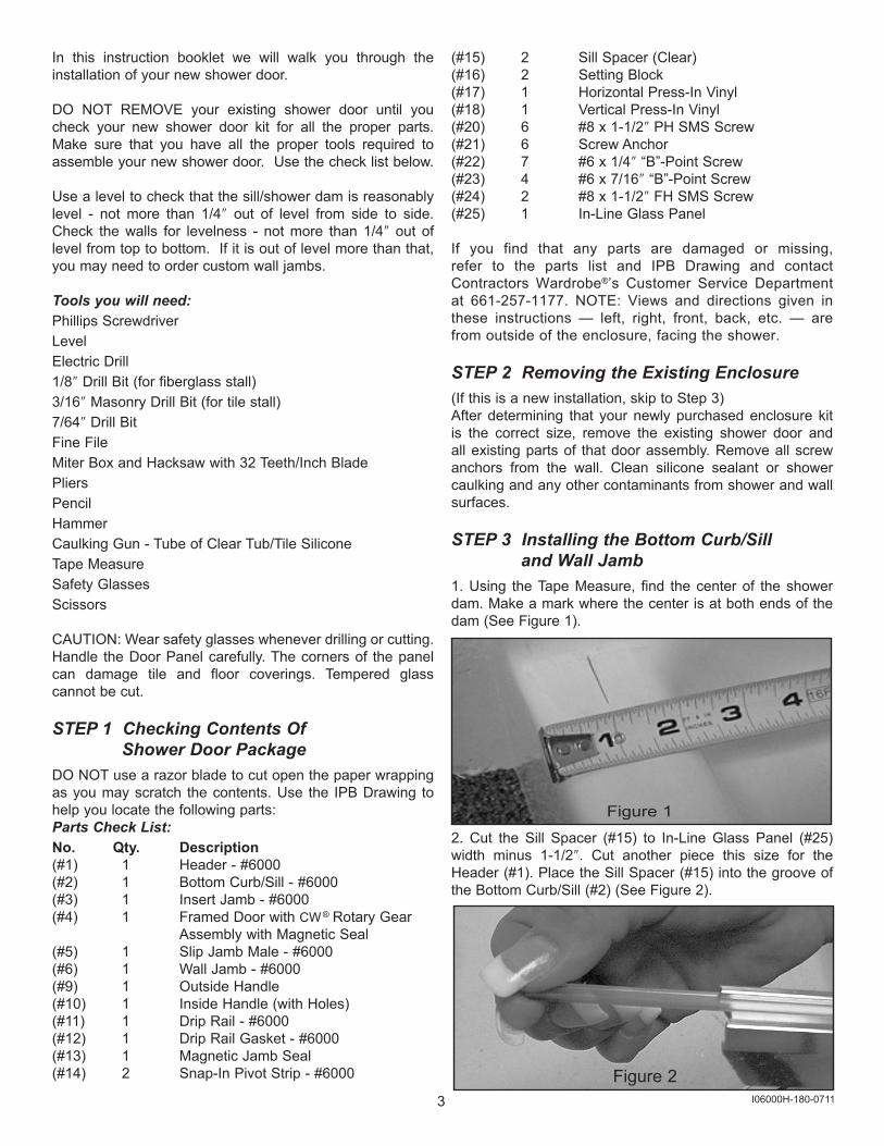
STEP 3 Installing the Bottom Curb/Sill and Wall Jamb1. Using the Tape Measure, find the center of the shower dam. Make a mark where the center is at both ends of the dam (See Figure 1).
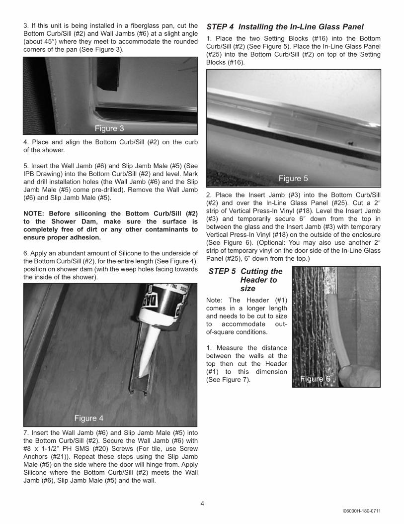
2. Cut the Sill Spacer (#15) to In-Line Glass Panel (#25) width minus 1-1/2″. Cut another piece this size for the Header (#1). Place the Sill Spacer (#15) into the groove of the Bottom Curb/Sill (#2) (See Figure 2).
Figure 23 I06000H-180-0711
Figure 1
4 I06000H-180-0711
3. If this unit is being installed in a fiberglass pan, cut the Bottom Curb/Sill (#2) and Wall Jambs (#6) at a slight angle (about 45°) where they meet to accommodate the rounded corners of the pan (See Figure 3).
4. Place and align the Bottom Curb/Sill (#2) on the curb of the shower.
5. Insert the Wall Jamb (#6) and Slip Jamb Male (#5) (See IPB Drawing) into the Bottom Curb/Sill (#2) and level. Mark and drill installation holes (the Wall Jamb (#6) and the Slip Jamb Male (#5) come pre-drilled). Remove the Wall Jamb (#6) and Slip Jamb Male (#5).
NOTE: Before siliconing the Bottom Curb/Sill (#2) to the Shower Dam, make sure the surface iscompletely free of dirt or any other contaminants to ensure proper adhesion.
6. Apply an abundant amount of Silicone to the underside of the Bottom Curb/Sill (#2), for the entire length (See Figure 4), position on shower dam (with the weep holes facing towards the inside of the shower).
7. Insert the Wall Jamb (#6) and Slip Jamb Male (#5) into the Bottom Curb/Sill (#2). Secure the Wall Jamb (#6) with #8 x 1-1/2″ PH SMS (#20) Screws (For tile, use Screw Anchors (#21)). Repeat these steps using the Slip Jamb Male (#5) on the side where the door will hinge from. Apply Silicone where the Bottom Curb/Sill (#2) meets the Wall Jamb (#6), Slip Jamb Male (#5) and the wall.
Figure 3
STEP 4 Installing the In-Line Glass Panel1. Place the two Setting Blocks (#16) into the Bottom Curb/Sill (#2) (See Figure 5). Place the In-Line Glass Panel (#25) into the Bottom Curb/Sill (#2) on top of the Setting Blocks (#16).
2. Place the Insert Jamb (#3) into the Bottom Curb/Sill (#2) and over the In-Line Glass Panel (#25). Cut a 2″ strip of Vertical Press-In Vinyl (#18). Level the Insert Jamb (#3) and temporarily secure 6″ down from the top in between the glass and the Insert Jamb (#3) with temporary Vertical Press-In Vinyl (#18) on the outside of the enclosure (See Figure 6). (Optional: You may also use another 2″strip of temporary vinyl on the door side of the In-Line Glass Panel (#25), 6” down from the top.)
STEP 5 Cutting the Header to sizeNote: The Header (#1) comes in a longer length and needs to be cut to size to accommodate out- of-square conditions.
1. Measure the distance between the walls at the top then cut the Header (#1) to this dimension (See Figure 7).
Figure 4
Figure 5
Figure 6

Figure 135
STEP 6 Installing the Sill Spacer1. Place the Sill Spacer (#15) into the groove of theHeader (#1).
STEP 7 Installing the Header and Snap-In Pivot Strip1. Place the Header (#1) over the vertical pieces of metal,as shown in Figure 8.
2. Drill assembly holes with a 7/64″ Drill Bit into the Header (#1) through the Slip Jamb Male (#5) and Wall Jamb (#6). Secure at the top, on both sides using #6 x 1/4″ “B”-Point Screws (#22) (See Figure 9).
3. Locate the Snap-In Pivot Strip (#14). Snap the Snap-In Pivot Strip (#14) into the Header/Curb (#1). Repeat this for the Header/Curb (#2) making sure the “raised” edge of the Snap-In Pivot Strip (#14) is to the outside of the unit.
STEP 8 Installing and Adjusting the Door and Insert JambInstalling the door panel may be easier if you havesomeone to assist you.
1. Temporarily install the Framed Door with CW ® Rotary Gear Hinge Assembly with Magnetic Seal (#4) into the Slip Jamb Male (#5). Mark and drill three installation holes. Insert the top, #6 x 1/4″ “B”-Point Screw (#22) only at this time (See Figure 11). Make sure that the door is level. Secure theCW ® Rotary Gear Hinge Assembly (#4) into the Slip Jamb Male (#5) with the remaining two #6 x 1/4″ “B”-Point Screws (#22).
Note: Magnetic Jamb Seal (#13) faces toward the outside of the shower. Once installed, if you find that the door will not stay closed, the magnet needs to be turned around. Remove the Magnetic Jamb Seal (#13) from the Insert Jamb (#3) and
reinsert it the other way.2. Insert the two #8 x 1-1/2″ FH SMS Screws (#24) into the Inside Handle (with Holes) (#10). Push the screws through the Door Panel and line up with the Outside Handle (#9). Tighten the screws. (See Figure 11).
3. Insert the middle#6 x 1/4″ “B”-Point Screw (#22) into the Slip Jamb Male (#5). You may have to flex the Slip Jamb Male (#5) for proper clearance once the door handle is in place.
4. Make sure that both the Door (#4) and the Insert Jamb (#3) are level. Secure the Insert Jamb (#3) to the Header (#1) with a #6 x 7/16″ “B”-Point Screw (#23). Repeat this step securing the Insert Jamb (#3) to the Bottom Curb/Sill (#2) with a #6 x 7/16″ “B”-Point Screw (#23).
Figure 7
Figure 8
I06000H-180-0711
Figure 9
Figure 11
Figure 10
STEP 9 Glazing the Vinyl into the In-Line Panel1. Remove the 2″ strips of temporary Vertical Press-InVinyl (#18) and shift In-Line Glass Panel (#25) to obtain sufficient overlap along both horizontal and vertical edges.
2. Push in the Horizontal Press-In Vinyl (large profile) (#17) from the outside between the glass and the Bottom Curb/Sill (#2) and Header (#1).This task is made easier by using a pen (as shown in Figure 12) to push the vinyl into Bottom Curb/Sill (#2) and Header (#1). Cut square covering the full width of the panel opening. Push the Vertical Press-In Vinyl (small profile) (#19) from the outside between the Wall Jamb (#6) and the Insert Jamb (#3).
STEP 10 Silicone Sealing the Enclosure1. Using the Clear Tub/Tile Silicone, seal all edges insideand outside where curb or walls meet the horizontal or vertical Jambs.
2. Standing inside the enclosure, seal the In-Line Glass Panel (#25), on the side and along the Bottom Curb/Sill (#2) (See Figure 13).
3. CW ® uses the “Wet Glaze” technique to secure the In- Line Glass Panel (#26) on the inside of the unit. Run the Clear Tub/Tile Silicone in between the glass and metal, around the entire inside perimeter (See Figures 14A and 14B). Follow manufacturer’s instructions for the sealant. Sealant must cure for 24 hours before using shower.
6 I06000H-180-0711
Figure 12
Figure 13
Figure 14A Figure 14B
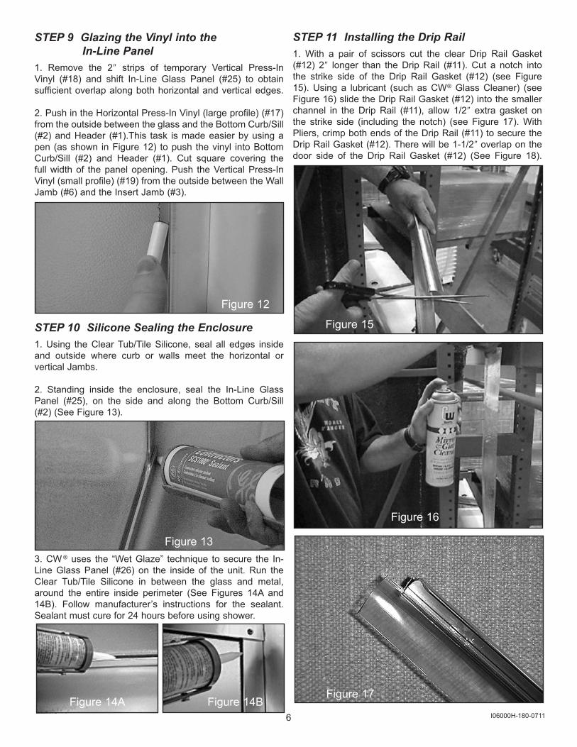
STEP 11 Installing the Drip Rail1. With a pair of scissors cut the clear Drip Rail Gasket (#12) 2″ longer than the Drip Rail (#11). Cut a notch into the strike side of the Drip Rail Gasket (#12) (see Figure 15). Using a lubricant (such as CW® Glass Cleaner) (see Figure 16) slide the Drip Rail Gasket (#12) into the smaller channel in the Drip Rail (#11), allow 1/2″ extra gasket on the strike side (including the notch) (see Figure 17). With Pliers, crimp both ends of the Drip Rail (#11) to secure the Drip Rail Gasket (#12). There will be 1-1/2″ overlap on the door side of the Drip Rail Gasket (#12) (See Figure 18).
Figure 17
Figure 15
Figure 16
7 I06000H-180-0711
Thank you for purchasing a CW® Shower Enclosure. This is only one of a large line of shower enclosures and high quality wardrobe door products. If you like this product, please contact Contractors Wardrobe® for more information about our many beautifulwardrobe doors in bi-pass and bi-fold styles with steel,aluminum and hardwood frames.
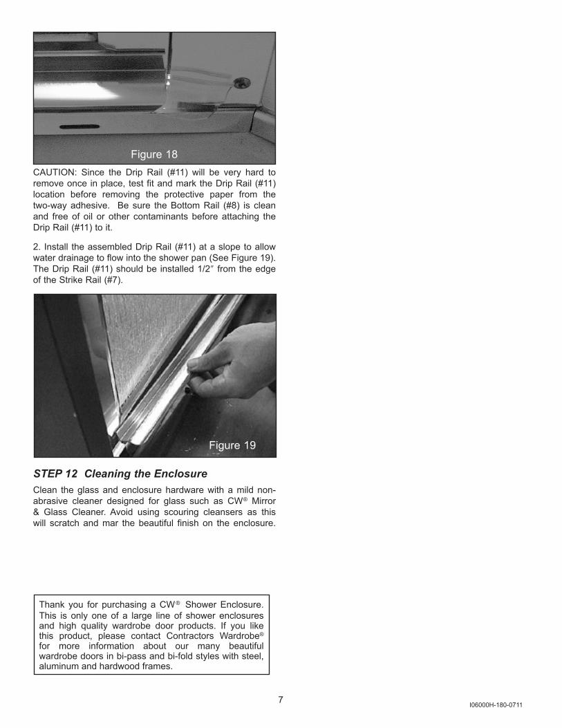
CAUTION: Since the Drip Rail (#11) will be very hard to remove once in place, test fit and mark the Drip Rail (#11) location before removing the protective paper from the two-way adhesive. Be sure the Bottom Rail (#8) is clean and free of oil or other contaminants before attaching the Drip Rail (#11) to it.
2. Install the assembled Drip Rail (#11) at a slope to allow water drainage to flow into the shower pan (See Figure 19). The Drip Rail (#11) should be installed 1/2″ from the edge of the Strike Rail (#7).
STEP 12 Cleaning the EnclosureClean the glass and enclosure hardware with a mild non-abrasive cleaner designed for glass such as CW® Mirror & Glass Cleaner. Avoid using scouring cleansers as this will scratch and mar the beautiful finish on the enclosure.
Figure 18
Figure 19