installation and on-line commissioning of ebis at...
TRANSCRIPT
INSTALLATION AND ON-LINE COMMISSIONING OF EBIS AT ATLAS*
P.N. Ostroumov†1, A. Barcikowski, J. Clark, C.A. Dickerson, M. Hendricks, Y. Luo, R.C. Pardo, C. Peters, M. Power, G. Savard, S.I. Sharamentov, R.C. Vondrasek, G. Zinkann,
Argonne National Laboratory, Argonne, 9700 S. Cass Av, IL 60439, USA 1also at FRIB, Michigan State University, 640 S. Shaw Lane, East Lansing, MI 48824, USA
Abstract
An Electron Beam Ion Source Charge Breeder (EBIS-CB) has been developed at Argonne to breed radioactive beams from the CAlifornium Rare Ion Breeder Upgrade (CARIBU) facility at ATLAS. The CARIBU EBIS-CB has been successfully commissioned offline with an external singly-charged cesium ion source [1]. The EBIS perfor-mance meets the breeding requirements to deliver CARIBU beams to ATLAS. EBIS can provide charge-to-mass ratios 1/7 for all CARIBU beams with breeding times in the range of 6 ms to 30 ms. A record high breeding efficiency of up to 28% into a single charge state of Cs28+ has been demonstrated. Following the offline testing EBIS was moved to the front end of ATLAS where the alignment of EBIS was substantially improved and additional beam diagnostic tools both for electron and ion beams were in-stalled. This paper will discuss EBIS improvements and present the results of on-line commissioning.
INTRODUCTION The major features of the CARIBU EBIS are: ultra-high
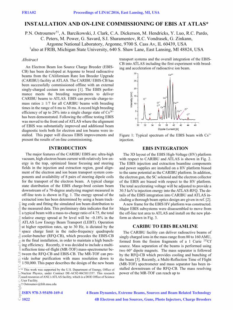
vacuum, high electron beam current with relatively low en-ergy in the trap, optimized linear focusing and steering fields in the injection and extraction region, good align-ment of the electron and ion beam transport system com-ponents and availability of 8 pairs of steering dipole coils for the transport of the electron beam. A typical charge state distribution of the EBIS charge-bred cesium beam downstream of a 70-degree analyzing magnet measured in off-line tests is shown in Fig. 1. The energy spread of the extracted ions has been determined by using a beam track-ing code and fitting the simulated ion beam distribution to the measured data. This preliminary data indicates that for a typical beam with a mass-to-charge ratio of 4.75, the total relative energy spread at 5 level will be ~0.18% in the ATLAS Low Energy Beam Transport (LEBT). Operation at higher repetition rates, up to 30 Hz, is dictated by the space charge limit in the radio-frequency quadrupole cooler-buncher (RFQ-CB), which precedes the EBIS-CB in the final installation, in order to maintain a high bunch-ing efficiency. Recently, it was decided to include a multi-reflection time-of-flight (MR-TOF) mass-spectrometer be-tween the RFQ-CB and EBIS-CB. The MR-TOF can pro-vide isobar purification with mass resolution down to 1/50,000. This paper describes the design of the new beam
transport systems and the overall integration of the EBIS-CB into ATLAS including the first experiment with breed-ing and acceleration of radioactive ion beam.
Figure 1: Typical spectrum of the EBIS beam with Cs1+ injection.
EBIS INTEGRATION The 3D layout of the EBIS High-Voltage (HV) platform
with respect to CARIBU and ATLAS is shown in Fig. 2. The EBIS injection and extraction beamline components and power supplies are installed on a HV platform biased to the same potential as the CARIBU platform. In addition, the electron gun, the SC solenoid and the electron collector of the EBIS are biased with respect to the HV platform. The total accelerating voltage will be adjusted to provide a 30.5 keV/u injection energy into the ATLAS-RFQ. The de-tails of the EBIS integration into CARIBU and ATLAS in-cluding a thorough beam optics design are given in ref. [2].
A new frame for the EBIS HV platform was constructed. Major EBIS subsystems were disassembled to move from the off-line test area to ATLAS and install on the new plat-form as shown in Fig. 3.
CARIBU TO EBIS BEAMLINE The CARIBU facility can deliver radioactive beams of
singly charged ions in the mass range from 80 to 160 AMU, formed from the fission fragments of a 1 Curie 252Cf source. Mass separation of the beams is performed using two 60° dipole magnets. The mass separator is followed by the RFQ-CB which provides cooling and bunching of the beam [3]. Recently, a Multi-Reflection Time of Flight (MR-TOF) spectrometer and mass separator has been in-stalled downstream of the RFQ-CB. The mass resolving power of the MR-TOF can reach up to
____________________________________________
* This work was supported by the U.S. Department of Energy, Office ofNuclear Physics, under Contract DE-AC02-06CH11357. This research used resources of ANL’s ATLAS facility, which is a DOE Office of ScienceUser Facility. † [email protected]
FR1A02 Proceedings of LINAC2016, East Lansing, MI, USA
ISBN 978-3-95450-169-41022Co
pyrig
ht©
2017
CC-B
Y-3.
0an
dby
ther
espe
ctiv
eaut
hors
4 Beam Dynamics, Extreme Beams, Sources and Beam Related Technology4B Electron and Ion Sources, Guns, Photo Injectors, Charge Breeders

Figure 2: 3D layout of the ATLAS front-end with the EBIS charge breeder.
Figure 3: General view of the EBIS.
Proceedings of LINAC2016, East Lansing, MI, USA FR1A02
4 Beam Dynamics, Extreme Beams, Sources and Beam Related Technology4B Electron and Ion Sources, Guns, Photo Injectors, Charge Breeders
ISBN 978-3-95450-169-41023 Co
pyrig
ht©
2017
CC-B
Y-3.
0an
dby
ther
espe
ctiv
eaut
hors
5104 for the period of time between the charge breeding cycles in the EBIS. The high mass resolving power is achieved for short beam pulses below 1 µs. To deliver beam from the MR-TOF to EBIS, we have designed an all-electrostatic beam transport system. The main goal of the beam optics design was the minimization of the emittance distortions due to aberrations and beam energy spread. Due to the very limited space, the beam is bent by 180 in the vertical plane immediately after the extraction from the MR-TOF as is shown in Fig. 2 and 4. The deflection of the low-energy, ~5 keV, beam by a substantial angle is chal-lenging due to the high geometrical emittance and relative energy spread. Spherical electrostatic 45° benders were de-signed to achieve isochronous beam transport with mini-mal emittance growth through two 180° bends. Immedi-ately following the 180 vertical bend after the MR-TOF, the beam is accelerated to higher energy to match the EBIS injection-extraction beamline which is designed to accept up to 50 keV beams [4]. While DC acceleration is possible, it would require the addition of a floating potential with a significant amount of equipment. To avoid that, a pulsed acceleration is employed in the two-gap pulsed accelerator (PA) shown in Fig. 4. In the PA, the ions are accelerated in the first accelerating gap and then enter a long drift tube. While the ion bunch is inside the drift tube the voltage of the tube is switched to a positive potential using a fast Beh-lke switch, so the ions are accelerated again in a second accelerating gap when they exit the tube. The length of the center drift tube was chosen to be 70 cm in order to accom-modate bunches with ∆t2.5 µs.
Figure 4: Side view of the beam transport system installed on the CARIBU platform. EB1-8 - 45° spherical electro-static benders; EL1 – Einzel lens; PA – Two-step Pulsed Accelerator; DS1 – Diagnostics Station; ED1-2 – Electro-static Doublets.
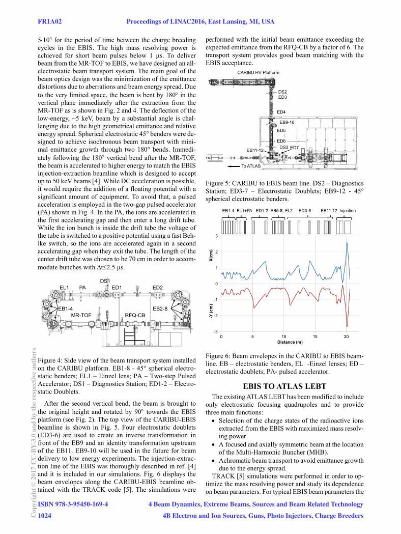
After the second vertical bend, the beam is brought to the original height and rotated by 90 towards the EBIS platform (see Fig. 2). The top view of the CARIBU-EBIS beamline is shown in Fig. 5. Four electrostatic doublets (ED3-6) are used to create an inverse transformation in front of the EB9 and an identity transformation upstream of the EB11. EB9-10 will be used in the future for beam delivery to low energy experiments. The injection-extrac-tion line of the EBIS was thoroughly described in ref. [4] and it is included in our simulations. Fig. 6 displays the beam envelopes along the CARIBU-EBIS beamline ob-tained with the TRACK code [5]. The simulations were
performed with the initial beam emittance exceeding the expected emittance from the RFQ-CB by a factor of 6. The transport system provides good beam matching with the EBIS acceptance.
Figure 5: CARIBU to EBIS beam line. DS2 – Diagnostics Station; ED3-7 – Electrostatic Doublets; EB9-12 - 45° spherical electrostatic benders.
Figure 6: Beam envelopes in the CARIBU to EBIS beam-line. EB – electrostatic benders, EL -Einzel lenses; ED – electrostatic doublets; PA- pulsed accelerator.
EBIS TO ATLAS LEBT The existing ATLAS LEBT has been modified to include
only electrostatic focusing quadrupoles and to provide three main functions: Selection of the charge states of the radioactive ions
extracted from the EBIS with maximized mass resolv-ing power.
A focused and axially symmetric beam at the location of the Multi-Harmonic Buncher (MHB).
Achromatic beam transport to avoid emittance growth due to the energy spread.
TRACK [5] simulations were performed in order to op-timize the mass resolving power and study its dependence on beam parameters. For typical EBIS beam parameters the
FR1A02 Proceedings of LINAC2016, East Lansing, MI, USA
ISBN 978-3-95450-169-41024Co
pyrig
ht©
2017
CC-B
Y-3.
0an
dby
ther
espe
ctiv
eaut
hors
4 Beam Dynamics, Extreme Beams, Sources and Beam Related Technology4B Electron and Ion Sources, Guns, Photo Injectors, Charge Breeders
mass resolving power is ~200. The achromatic properties of two 90 magnets are provided by adding two large-ap-erture electrostatic quadrupole doublets located next to the magnets (see Fig. 2). A small beam size is formed in the MHB and appropriate beam matching into the RFQ is pro-vided [2]. There are no beam losses and no emittance growth along the LEBT.
BEAM DIAGNOSTICS A set of beam diagnostics tools have been designed, built
and installed in the CARIBU-EBIS and LEBT beamlines. The beam diagnostics system allows us to tune beam transport lines both for stable ion guide beams and radio-active low-intensity beams. Charge bred residual gas or stable 133Cs injected from a dedicated surface ionization source are used as guide beam in the EBIS to ATLAS LEBT. The beam diagnostics system includes: Shielded Faraday Cups (FC). Both signal and bias
electrodes are well shielded and grounded to the beam pipe to reduce the background noise.
FCs based on multichannel plates (MCP). This FC measures the intenisty of secondary electrons created by ions bombarding the MCP.
Pepper-pot emittance probes with MCPs. The image of secondary electrons on a phosphor screen is used to extract the beam emittance. The secondary electrons are created by ions bombarding the MCP.
Annular MCPs. The primary ion beam generates sec-ondary electrons from an aluminium target. The elec-trons are accelerated backwards and collected by the annular MCP.
Silicon detectors for the measurement of radioactive beam intensity by counting β–decay events.
EBIS BEAM ACCELERATION IN ATLAS The installation of the EBIS and the LEBT section con-
necting it to the ATLAS followed by sub-system check-out and interlocks testing were completed in April 2016. The initial EBIS commissioning and first beam acceleration in the Positive Ion Injector (PII) up to 1.84 MeV/u were per-formed using 16O6+ beam created from the residual gas in the EBIS trap. The oxygen beam extracted from the EBIS trap in a pulsed mode with 1 Hz repletion rate was successfully accelerated in ATLAS. The main goal of the experiments was to accelerate beam through PII with a good efficiency. This goal was achieved and transmission efficiency was measured to be 75.4% while the theoretical value is 83%. Figure 7 shows the oxygen beam signal from the FC located after the PII. The pulsed signal is integrated due to the cable capacitance of 126 pF. The collected charge corresponds to 2.2 106 oxygen ions per pulse.
Figure 7: Oxygen 6+ beam signal from the FC located at the exit of PII section of ATLAS.
In the following months, the EBIS has been operated at a 10 Hz repetition rate with a cesium beam.
BREEDING AND ACCELERATION OF RARE ISOTOPES
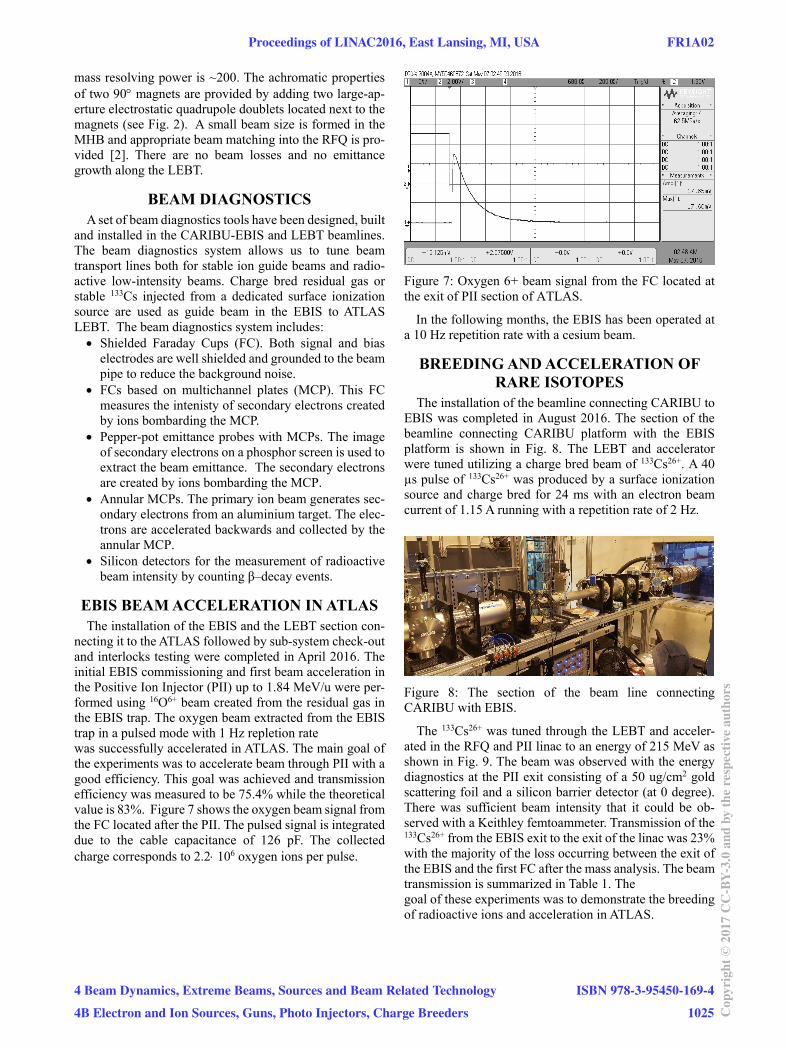
The installation of the beamline connecting CARIBU to EBIS was completed in August 2016. The section of the beamline connecting CARIBU platform with the EBIS platform is shown in Fig. 8. The LEBT and accelerator were tuned utilizing a charge bred beam of 133Cs26+. A 40 µs pulse of 133Cs26+ was produced by a surface ionization source and charge bred for 24 ms with an electron beam current of 1.15 A running with a repetition rate of 2 Hz.
Figure 8: The section of the beam line connecting CARIBU with EBIS.
The 133Cs26+ was tuned through the LEBT and acceler-ated in the RFQ and PII linac to an energy of 215 MeV as shown in Fig. 9. The beam was observed with the energy diagnostics at the PII exit consisting of a 50 ug/cm2 gold scattering foil and a silicon barrier detector (at 0 degree). There was sufficient beam intensity that it could be ob-served with a Keithley femtoammeter. Transmission of the 133Cs26+ from the EBIS exit to the exit of the linac was 23% with the majority of the loss occurring between the exit of the EBIS and the first FC after the mass analysis. The beam transmission is summarized in Table 1. The goal of these experiments was to demonstrate the breeding of radioactive ions and acceleration in ATLAS.
Proceedings of LINAC2016, East Lansing, MI, USA FR1A02
4 Beam Dynamics, Extreme Beams, Sources and Beam Related Technology4B Electron and Ion Sources, Guns, Photo Injectors, Charge Breeders
ISBN 978-3-95450-169-41025 Co
pyrig
ht©
2017
CC-B
Y-3.
0an
dby
ther
espe
ctiv
eaut
hors
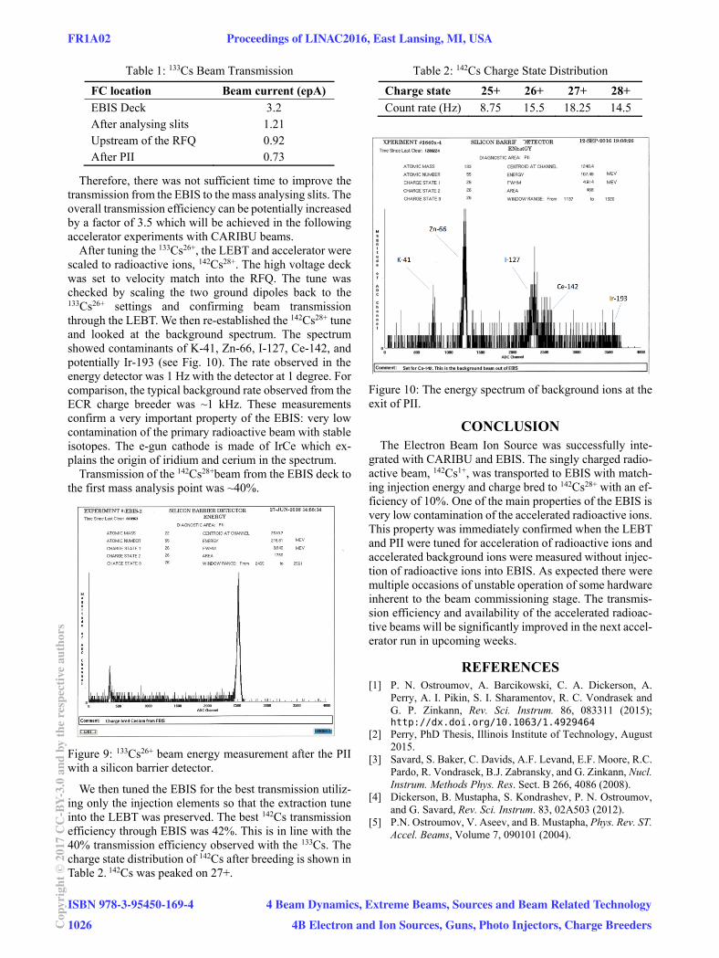
Table 1: 133Cs Beam Transmission
FC location Beam current (epA)
EBIS Deck 3.2 After analysing slits 1.21 Upstream of the RFQ 0.92 After PII 0.73
Therefore, there was not sufficient time to improve the transmission from the EBIS to the mass analysing slits. The overall transmission efficiency can be potentially increased by a factor of 3.5 which will be achieved in the following accelerator experiments with CARIBU beams.
After tuning the 133Cs26+, the LEBT and accelerator were scaled to radioactive ions, 142Cs28+. The high voltage deck was set to velocity match into the RFQ. The tune was checked by scaling the two ground dipoles back to the 133Cs26+ settings and confirming beam transmission through the LEBT. We then re-established the 142Cs28+ tune and looked at the background spectrum. The spectrum showed contaminants of K-41, Zn-66, I-127, Ce-142, and potentially Ir-193 (see Fig. 10). The rate observed in the energy detector was 1 Hz with the detector at 1 degree. For comparison, the typical background rate observed from the ECR charge breeder was ~1 kHz. These measurements confirm a very important property of the EBIS: very low contamination of the primary radioactive beam with stable isotopes. The e-gun cathode is made of IrCe which ex-plains the origin of iridium and cerium in the spectrum.
Transmission of the 142Cs28+beam from the EBIS deck to the first mass analysis point was ~40%.
Figure 9: 133Cs26+ beam energy measurement after the PII with a silicon barrier detector.
We then tuned the EBIS for the best transmission utiliz-ing only the injection elements so that the extraction tune into the LEBT was preserved. The best 142Cs transmission efficiency through EBIS was 42%. This is in line with the 40% transmission efficiency observed with the 133Cs. The charge state distribution of 142Cs after breeding is shown in Table 2. 142Cs was peaked on 27+.
Table 2: 142Cs Charge State Distribution
Charge state 25+ 26+ 27+ 28+
Count rate (Hz) 8.75 15.5 18.25 14.5
Figure 10: The energy spectrum of background ions at the exit of PII.
CONCLUSION The Electron Beam Ion Source was successfully inte-
grated with CARIBU and EBIS. The singly charged radio-active beam, 142Cs1+, was transported to EBIS with match-ing injection energy and charge bred to 142Cs28+ with an ef-ficiency of 10%. One of the main properties of the EBIS is very low contamination of the accelerated radioactive ions. This property was immediately confirmed when the LEBT and PII were tuned for acceleration of radioactive ions and accelerated background ions were measured without injec-tion of radioactive ions into EBIS. As expected there were multiple occasions of unstable operation of some hardware inherent to the beam commissioning stage. The transmis-sion efficiency and availability of the accelerated radioac-tive beams will be significantly improved in the next accel-erator run in upcoming weeks.
REFERENCES [1] P. N. Ostroumov, A. Barcikowski, C. A. Dickerson, A.
Perry, A. I. Pikin, S. I. Sharamentov, R. C. Vondrasek and G. P. Zinkann, Rev. Sci. Instrum. 86, 083311 (2015); http://dx.doi.org/10.1063/1.4929464
[2] Perry, PhD Thesis, Illinois Institute of Technology, August 2015.
[3] Savard, S. Baker, C. Davids, A.F. Levand, E.F. Moore, R.C. Pardo, R. Vondrasek, B.J. Zabransky, and G. Zinkann, Nucl. Instrum. Methods Phys. Res. Sect. B 266, 4086 (2008).
[4] Dickerson, B. Mustapha, S. Kondrashev, P. N. Ostroumov, and G. Savard, Rev. Sci. Instrum. 83, 02A503 (2012).
[5] P.N. Ostroumov, V. Aseev, and B. Mustapha, Phys. Rev. ST. Accel. Beams, Volume 7, 090101 (2004).
FR1A02 Proceedings of LINAC2016, East Lansing, MI, USA
ISBN 978-3-95450-169-41026Co
pyrig
ht©
2017
CC-B
Y-3.
0an
dby
ther
espe
ctiv
eaut
hors
4 Beam Dynamics, Extreme Beams, Sources and Beam Related Technology4B Electron and Ion Sources, Guns, Photo Injectors, Charge Breeders