inductrack demonstration model - askmar.com inductrack demonstration model.pdfabstract a small-scale...
TRANSCRIPT

R. F. Post
February 3, 1998
Inductrack Demonstration Model
This is an informal report intended primarily for internal or limited externaldistribution. The opinions and conclusions stated are those of the author and mayor may not be those of the Laboratory.
Work performed under the auspices of the U.S. Department of Energy by theLawrence Livermore National Laboratory under Contract W-7405-Eng-48.
Lawre
nce
Liverm
ore
National
Labora
tory
UCRL-ID-129664

DISCLAIMER
This document was prepared as an account of work sponsored by an agency of the United States Government. Neitherthe United States Government nor the University of California nor any of their employees, makes any warranty, expressor implied, or assumes any legal liability or responsibility for the accuracy, completeness, or usefulness of anyinformation, apparatus, product, or process disclosed, or represents that its use would not infringe privately ownedrights. Reference herein to any specific commercial product, process, or service by trade name, trademark,manufacturer, or otherwise, does not necessarily constitute or imply its endorsement, recommendation, or favoring bythe United States Government or the University of California. The views and opinions of authors expressed herein donot necessarily state or reflect those of the United States Government or the University of California, and shall not beused for advertising or product endorsement purposes.
This report has been reproduceddirectly from the best available copy.
Available to DOE and DOE contractors from theOffice of Scientific and Technical Information
P.O. Box 62, Oak Ridge, TN 37831Prices available from (615) 576-8401, FTS 626-8401
Available to the public from theNational Technical Information Service
U.S. Department of Commerce5285 Port Royal Rd.,
Springfield, VA 22161

1
Inductrack Demonstration Model
R. F. PostLawrence Livermore National Laboratory
Abs t rac t
A small-scale model track of a new type of magnetic levitationsystem (dubbed the "Inductrack" system), and a passivelymagnetically levitated cart, has been designed, constructed a n doperated. The track consists of a close-packed array of rectangularlevitation coils, 15 centimeters in width transversely and 20 mete rsin length. The array of coils is inductively loaded above and belowits lower horizontal section with ferrite tiles. Paralleling t h elevitation coils on each side are aluminum-channel rails on whichride auxiliary wheels attached to the cart. The cart has, on its lowersurface and on its sides, fore and aft, special arrays ("Halbacharrays") of permanent magnet bars that produce a strong periodicmagnetic field below the cart. This magnetic field, when the cart is i nmotion, induces repelling currents in the Inductrack coils, levitatingit and centering it transversely. When mechanically launched (wi tha pulley-and-weight system) at speeds substantially above a"transition speed" of about 2 meters per second, the cart levi tatedand flew stably down the track, settling to rest on its wheels near theend of the track. In the last phase of the program an electromagneticlaunching section consisting of another array of coils, connected t opulse-driver circuits, was added at the beginning of the track. Aidedby an initial launch (from stretched "bungee" cords), th iselectromagnetic launching system was operated successfully,resulting again in levitation and subsequent stable flight of the cart.
(I) Introduction: The Inductrack Concept
The Inductrack concept is a passive magnetic levitation sys temfor moving objects that employs special arrays of permanentmagnets in the moving object. The magnetic field from these a r raysinduces currents in the "track" that, by interacting with the magneticfield, produce strong lifting forces. By contrast with other magneticlevitation systems, no superconducting magnet coils or servo controlcircuits are required and the ratio of lifting force to drag force ismuch higher than magnetic levitation systems that rely on e d d ycurrents induced in conducting surfaces.
2
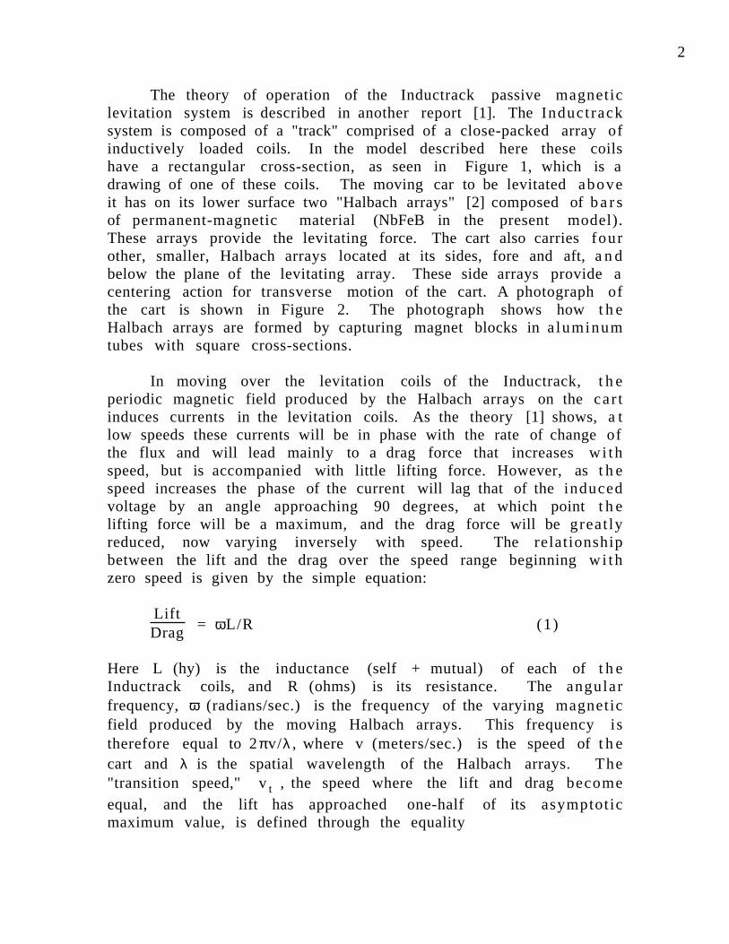
The theory of operation of the Inductrack passive magneticlevitation system is described in another report [1]. The Inductracksystem is composed of a "track" comprised of a close-packed array ofinductively loaded coils. In the model described here these coilshave a rectangular cross-section, as seen in Figure 1, which is adrawing of one of these coils. The moving car to be levitated aboveit has on its lower surface two "Halbach arrays" [2] composed of ba rsof permanent-magnetic material (NbFeB in the present model).These arrays provide the levitating force. The cart also carries fourother, smaller, Halbach arrays located at its sides, fore and aft, a n dbelow the plane of the levitating array. These side arrays provide acentering action for transverse motion of the cart. A photograph ofthe cart is shown in Figure 2. The photograph shows how t h eHalbach arrays are formed by capturing magnet blocks in a luminumtubes with square cross-sections.
In moving over the levitation coils of the Inductrack, t h eperiodic magnetic field produced by the Halbach arrays on the car tinduces currents in the levitation coils. As the theory [1] shows, a tlow speeds these currents will be in phase with the rate of change ofthe flux and will lead mainly to a drag force that increases w i thspeed, but is accompanied with little lifting force. However, as t h espeed increases the phase of the current will lag that of the inducedvoltage by an angle approaching 90 degrees, at which point t h elifting force will be a maximum, and the drag force will be great lyreduced, now varying inversely with speed. The relationshipbetween the lift and the drag over the speed range beginning w i thzero speed is given by the simple equation:
LiftDrag = ωL/R (1)
Here L (hy) is the inductance (self + mutual) of each of t h eInductrack coils, and R (ohms) is its resistance. The angularfrequency, ω (radians/sec.) is the frequency of the varying magneticfield produced by the moving Halbach arrays. This frequency istherefore equal to 2πv/λ , where v (meters/sec.) is the speed of t h ecart and λ is the spatial wavelength of the Halbach arrays. The"transition speed," vt , the speed where the lift and drag becomeequal, and the lift has approached one-half of its asymptot icmaximum value, is defined through the equality
3
ωL/R = 1.0, i.e., vt = (λ /2π)(R/L) m./sec. (2)
Since the quantity R/L generally decreases upon scale-up ofthe size of the Inductrack coil array, small-scale models typicallyrequire a higher launching speed than would a full-size system. Aswill be later calculated, the transition speed for the model that w a sbuilt is about 2 meters/sec., (7 km/hr) to be contrasted with atransition speed of order 1.5 km/hr (0.4 meters/sec.) that might b etypical of a full-scale system. In this respect, therefore, t h econstruction of a small model carries with it a more difficultrequirement (higher launching speed) than would larger systems.
In brief review of the theory of the levitating force that isproduced at speeds that are high compared to the transition speedsthe limiting value of this force per unit area is given by the equation:
Fmax
A = B
20
µ0 exp -k (2y + ∆ c) Newtons/m2 (3)
Here the quantity B0 (Tesla) , defined in an equation below, isthe peak value of the magnetic field at the lower surface of t h eHalbach array, y (m.) is the distance from that surface to the u p p e rsurface of the Inductrack coil array, and ∆c (m.) is the thickness i n
the vertical direction of the conductor bundle. The quantity k (m-1 )is equal to 2π/λ , where λ (m.) is the wavelength of the Halbach array.The constant µ0 is equal to 4π x 10-7 henrys/meter, t h epermeability of free space in SI units.
In terms of the remanent magnetic field of the permanent -magnet material, the value of B0 , as calculated by Halbach [2], isgiven by the equation:
B0 = Br [ ]1 - e x p ( - k d ) sin(π/M )
π/ M Tesla (4)
Here d (m.) is the thickness in the vertical direction of t h eHalbach array, and M is equal to the number of magnet elements p e rwavelength (M = 4 in the model as constructed). A "magnet element"as here defined corresponds to a sub-group in the array, consisting ofone or more actual bars, within which the direction of magnetization

4
is the same. In the case of square magnet bars, with a single bar p e rsub-group, the equation takes on the value:
B0 = (0.713)Br Tesla (5)
For standard-grade NdFeB magnet material, Br = 1.23 Tesla, sothat B0 = 0.877 Tesla. Inserting this value into equation (3) t he reresul ts
Fmax
A = 6 x 10⁵ exp -k (2y + ∆ c) Newtons/m2 (6)
In this case for small separations (ky << 1), and small conductorthickness (k∆c << 1), the limiting levitating force is seen to approach
60 metric tonnes/m2 .
How close it is possible to approach the limiting levitation forcedepends on the design of the Inductrack coils and on the amount ofextra inductive loading that is used to augment the intrinsicinductance of the coils (i.e, taking into account both self- and mutua l -inductance effects). Adding inductive loading leads to lowering t h etransition speed and to increasing the lift/drag ratio at high speeds.When these effects are taken into consideration the magnitude of t h elevitating force is reduced, leading to the following expression for t h eratio of the available levitating force to its limiting value:
Fy
Fmax =
wPc
Ld
L L + Ld (7)
Here w (m.) is the transverse width of the Halbach array, Pc (m.) isthe perimeter of the coil, Ld (hy) - called the "distr ibutedinductance," and defined below - is the self-inductance of a coil, a saugmented by mutual-inductance coupling to the adjacent coils ofthe track, and LL (hy) is the extra inductive loading that may b eadded (in the case of the model, through the use of ferrite tiles). Thetotal inductance, L, is then equal to the sum of these two terms, i.e., L= LL + Ld
As calculated by Ryutov [1], the value of Ld is given by t h erelationship:

5
L d = µ0Pc
2kdc h y (8)
Here dc (m.) is the separation distance between the midplanes ofadjacent coils, which for close-packed coils is just equal to their axialthickness. Equation (8) applies to the "one-turn-equivalent" coil t h a twould be represented by a one-turn coil carrying a uniformlydistributed current and having the same conductor cross-section a n dperimeter as the multi-turn litz-wire coil actually used in t h eexperiment. As can be seen from the scaling laws for the L/R ratio ofsuch coils, these two coils, i.e., the "one-turn-equivalent" and t h eactual coil, have the same geometry and the same value of L/R, t huswould behave identically in an Inductrack.
For the specific case of inductive loading by ferrite t i lesanother calculation made by Ryutov [3] gives the following result forthe term in equation (7) involving the ratio of inductances:
Ld
L L + Ld =
1
1 + hPc
(Q-1) (9)
Here the quantity h (m.) is the transverse width of the two ferr i tetiles. As shown in Figure 3 these tiles lie on the upper and lowersurfaces of the lower leg of the coil. The quantity Q, represent ingthe effect of the ferrite tiles in enhancing the inductance, is in t h elimit of high permeability of the tiles, i.e., µ >> µ0 , given by t h eequation:
Q = exp(ka/2) + exp(-ka/2)
exp (ka /2 ) - exp ( - ka /2 ) (10)
Here a (m.) is the vertical thickness of the lower leg of a coil of t h earray.
As can be seen from the form of equation (9), it can b erearranged to define the ratio of the added inductive loading LL (hy) to the distributed inductance, Ld (hy) , through the relation:

6
LL
Ld =
hPc
(Q-1) (11)
Equations (1) through (11) may now be used to calculate t h eimportant parameters of the model Inductrack that was constructed.In these calculations we will ignore small corrections in the levitationand other parameters associated with the auxiliary Halbach a r rayson each side of the car (see Figure 2). These arrays provide restoringforces for sideways motions of the car during its flight down t h etrack.
(II) Calculation of Parameters of Model
The model Inductrack was designed on the basis of the theoryoutlined above. The first parameter required was the requ i redlaunching speed, as this dictated the design of the mechanicallauncher used in the first tests. The critical parameter here is t h etransition speed, vt , defined through equation (2) and equations (8),(10), and (11). Referring to Figure 1 for the coil, the re levantparameters here include its mean perimeter, Pc = 0.51 m., that it iswound with 53 turns of 150/36 litz wire (150 strands of 36 AWGcopper wire), and that its thickness, ∆c = 0.0125 m. The resistance of36 AWG wire is 1.36 ohms/meter so that the one-turn-equivalentresistance, R, of the coil is (1.36 x 0.51)/(53 x 150) = 8.7 x 10⁻⁵ ohm.
The one-turn-equivalent inductance of the coil,L d (i.e., before ferrite loading) , can be calculated from equation (8)by inserting the values for k and for dc . From Figure 2 for the car twe see that the wavelength of the Halbach array is equal to 4 t imesthe length of one magnet block. These magnet blocks were each .025m. in dimension, so that λ = 0.10 m. and k = 62.8 m-1 . From Figure 1we find for the mean separation distance, dc , the value .016 m.Inserting these values into equation (8) we find for Ld the va lue0.63 microhenrys.
The one-turn-equivalent inductance of the coils, including t h eeffect of the ferrite tiles, can be calculated using equations (10) a n d(11), by inserting a = ∆c = 0.0125 m in equation (10), and h = 0.1 m.for the width of the tiles in equation (11). We find for Q the va lue2.6, from which we find for the ratio of inductive loading to t h e

7
distributed inductance the value 0.329. Thus the one- turnequivalent inductance, L = (LL + Ld ) = 0.63 + (0.329 x 0.63) = 0.84microhenrys.
The transition speed, vt = (1/k)[R/L] can now be evaluated,finding vt = 1.7 m/sec., the speed at which the lift/drag ratio is 1.0,and the lift has approached one-half of its asymptotic value. I norder for the cart to fly for any substantial distance after launch, i tslaunching speed must be considerably above this speed. In the testswe launched the cart at speeds of about 10 meters/sec. in order t ohave it fly in a levitated state for nearly the full length of the tes ttrack.
The next parameter to be calculated is the expected levitationheight, y (m.), at speeds that are substantially above the transit ionspeed. For this we need the mass of the cart which is 22 kilograms,and the width of the levitating Halbach arrays, w = 0.125 m. Fromequation (7) for the ratio of the achieved levitating force to i tsmaximum value we find, using the parameters already calculated:
Fy
Fmax =
wPc
Ld
L L + Ld = 0.184 (12)
Using this ratio and equation (6) we find for the levitating forceat speeds high compared to the transition speed the expression:
Fy
A = 1.1 x 10⁵ exp -k (2y + ∆ c) Newtons/m2 (13)
Each of the levitating Halbach arrays is 0.2 m. long and 0.125m. wide, so that the total levitating area of these arrays (ignoringedge effects) is .05 m2 ., so that the equation for the levitating forceas a function of height, y (m.) becomes:
Fy = 5.5 x 10³ exp -k (2y + ∆ c) Newtons (14)
Now inserting the required levitating force = Mg = 216 Newtons, w emay solve this equation for the levitation height, y (m.), (ignoring

8
small corrections from edge effects and from the effect of the s ide-mounted Halbach arrays). We find the value y = 0.02 m.
The final quantity that we will calculate is the expected flightdistance as a function of the launching speed and the R/L ratio. Thisquantity can be evaluated by noting that the equation for t h elift/drag ratio, equation (1), can be written as:
LiftDrag = Kv, where K = k(L/R) = 1/vt = 0.59 sec./m. (15)
Integration of the 1-D equation of motion of the cart then yields a nequation for the flight distance, here defined as the distance at whichthe speed of the cart becomes equal to zero. In terms of i tslaunching speed, v0 (m./sec.) , the equation derived for the flightdistance, zmax (m.) , is:
zmax = 13
Kv
30
g mete rs (16)
At a launch speed of 10 m./sec. this equation predicts a flightdistance of about 20 meters, which is approximately the full lengthof the track. This result agrees roughly with the observations, whichshowed flight distances of order the length of the track for launchingspeeds of order of (slightly higher than) 10 meters/sec. Thediscrepancy can probably be accounted for by effects ignored in th iscalculation, i.e., (1) edge effects in the Halbach arrays, reducing the i rlift force by 10 percent or so as compared to the theory, (2) t h eextra drag introduced by the side-mounted Halbach arrays, and (3)aerodynamic drag (probably a small correction). In some of t h etests, in particular those with the electronic drive, the launch velocitywas measured at the end of the launching region, which was somemeters away from the beginning of the levitating region. In thesecases the speed at launch would be somewhat lower than t h emeasured speed, owing to frictional losses in the intermediatesection.
Finally, though difficult to observe, the flight heights of the car twere certainly not far from the 2 cm. value predicted by the theory.We conclude that the theoretical formulae used to design and t opredict the performance of the Inductrack model were general ly

9
corroborated by the experimental results. We also conclude from t h eanalysis of the high-speed video shots of the cart in motion that,apart from transients caused at launch, the motion of the car tshowed no signs of instability in flight, again in agreement with t h epredictions of the theory presented in reference [1].
(III) Electronic Drive
In the last phase of the investigations of the Inductrack modelelectronic drive circuits were introduced at the beginning of t h etrack. These circuits were employed to accelerate the cart to launchspeeds. Within the time and funding limitations it was not possibleto complete the full complement of circuits, but with a starting assistfrom stretched "bungee" cords launching speeds in excess of 1 0meters per second were achieved, resulting in stable flights overnearly the full length of the test track.
In the electronic drive a set of 45 coils of the same type as t h elevitating coils were mounted in a spaced array (spacing 0.1 m.) t h a twas 4.5 m. long, located just before the beginning of the levitatingtrack. These coils were energized by half-sine-wave pulses der ivedfrom the discharge of electrolytic condensers (operating voltage =400 V., total capacity = 3600 mfd.) through silicon-controlled-rectifiers (SCRs). Figure 4 is a photograph of two of the pulse-dr ivermodules with their electrolytic condensers and SCRs and protect ivediodes mounted on the assembly.
The SCRs were triggered by impulses from small microswitchesspaced along the track at the position of the drive coils. Theseswitches were activated by a mechanical "paddle" carried on the car titself, thus guaranteeing synchronization of the drive-current pulseswith the position of the cart, in particular, with the vertical f ieldcomponent produced by the front Halbach array at a position hal f -way back from its front edge.
The peak currents from the drive circuits were of order 4 0 0amperes, and the pulse durations produced by the circuits were oforder 3 to 5 ms. (depending on position down the track; shorter n e a rthe far end). Since the coils that were used had 53 turns, t h eeffective transverse current, seen by the Halbach arrays a n dproducing the drive impulses, was about 20,000 amperes. Thiscurrent then produced an impulsive force, the peak value of which

1 0
can be estimated from the calculated peak strength of the magneticfield at the position of the drive coil given by the relationship:
By = B0 exp[-k(y + ∆c /2)] Tesla (17)
Here (y + ∆c /2) is approximately .025 m. The peak force then isgiven by:
Fz(max) = By w I = [(0.713)(1.23)][exp(-62.8x.0.025)][0.125][2x10⁴ ]
= 4.6 x 10² Newtons
Thus the peak instantaneous value of the "g" acceleration of the car twhile passing over a coil of the electronic drive is approximately (4.6x 10² )/(22 x 9.8) = 2.1 g. The average "g" value was, of course,smaller, corresponding to a value of about 1.1 g, as estimated f romthe length of the electronic-drive portion of the track and t h eachieved launching velocities.
(IV) Conclusion
We have designed, constructed, and operated a modelInductrack passive magnetic levitation system. The design w a sbased on a theoretical analysis which predicts the levitation forcesand the lift-to-drag ratios for such systems. As also predicted by t h etheory the levitated motion was found to be stable. Reasonableagreement was also found between the experimental results and t h etheory for the levitation height and the flight distances for t h elevitated cart, giving confidence in the validity of the theory forextrapolation to larger-scale systems.
(V) Acknowledgements
The considerable assistance of Dmitri Ryutov in the theoreticalanalysis, of J. Ray Smith in designing the gravity-drive system and i noverseeing the operation of the model, of Edward Cook in the designof the electronic circuits, and of William Kent in constructing,assembling, and operating the Inductrack model is grateful lyacknowledged.
Work performed under the auspices of the U. S. Department of Energy by the LawrenceLivermore National Laboratory under Contract W-7405-48

1 1
Re fe rences
[1] R. F. Post, D. D. Ryutov, "The Inductrack Concept: a New Approach to Magnetic Levitation," Report UCRL-ID-124115, May 1996
[2] K. Halbach, "Application of Permanent Magnets in Accelerators and Electron Storage Rings," Journal of Applied Physics, 57, 3605 (1985)
[3] D. D. Ryutov (private communication)
Figure Captions
Figure 1: Drawing of a typical levitating coil and a cross-section of the windings showing the number of turns and type of wire.
Figure 2: Front-view photograph of the cart and the track coil assembly. The cart is shown at its approximate height of levitation in flight above the track.
Figure 3: Schematic drawing of a cross-section of the track coil assembly showing the location of the ferrite tiles used for inductive loading.
Figure 4: Photograph of two of the electronic drive modules used to launch the cart down the track
1 2
A A
6"
3"
Section A-A (not to scale)
53 turns .080" diam.litz wire
Inductrack Model Coil
Figure 1

1 3
Figure 2

1 4
Coil
Ferrite "Tile"
Schematic Drawing of Inductrack Model Track
Wood
Figure 3

1 5
Figure 4