redesign of rotary inductrack for magnetic levitation
TRANSCRIPT

Redesign of Rotary Inductrack for Magnetic Levitation Train Demonstration
Student: Glenn Zomchek
Advisors: Dr. Anakwa
Mr. Gutschlag
Date: May 18, 2007
Bradley University Department of
Electrical and Computer Engineering
PDF Created with deskPDF PDF Writer - Trial :: http://www.docudesk.com

ABSTRACT
The goal of this project is to demonstrate Halbach array train levitation using a current generating rotary inductrack to create a magnetic force strong enough to levitate a small train. A digital force gauge is attached to the structure to measure the force felt by the train while a position transducer measures the displacement in height created by the train levitation. This project is a small-scale model of a life-size track and train levitation system.
PDF Created with deskPDF PDF Writer - Trial :: http://www.docudesk.com

Table of Contents
Project Summary .……………………………………………… 1 Inductrack Maglev Method ……………………………………. 1 Block Diagrams and Subsystems ……………………………… 1 Halbach Array ………………….……………………………… 3 Halbach Array Simulations …….……………………………… 3 Train Fabrication ………………….…………………………… 4 Inductrack …...………………….……………………………… 5 Rotary Wheel ………………….……………………………….. 6 Design Equations ……………….……………………………… 7 Experimental Setup …………….………………………………. 8 Experimental Results …………….…………………………….. 10 Discussion of Results …………….……………………………. 19 Specifications ………………….………………………………. 21 Equipment Purchased …………….……………………………. 22 Patents …………………………………………………………. 23 Acknowledgements ……………………………………………. 24 Bibliography …………………………………………………… 25
PDF Created with deskPDF PDF Writer - Trial :: http://www.docudesk.com

List of Tables and Figures
Figure 1 – Overall System Block Diagram ……………………… 1 Figure 2 – Rotary Subsystem Block Diagram …………………... 2 Figure 3 – Levitation Subsystem Block Diagram ……………….. 2 Figure 4 – Standard Halbach Array Configuration ……………… 3 Figure 5 – Simulated Halbach Array ……………………………. 4 Figure 6 – Constructed Trains …………………………………... 4 Figure 7 – Laminated Sheets Inductrack ………………………... 5 Figure 8 – Bicycle Wheel ………………..……………………… 6 Figure 9 – Bicycle Wheel with Inductrack ……………………… 6 Figure 10 – 6 Inch Diameter Aluminum Drum Wheel ………….. 7 Figure 11 – 6 Inch Polyethylene Wheel …………………………. 7 Figure 12 – Force Gauge Instrument Support Structure ………… 8 Figure 13 – Position Transducer Support Structure ……………... 9 Figure 14 – Underside View of Position Transducer Support Structure ………………………………………………………... 10 Table 1 – Experimental Test with Aluminum Wheel 0.5 cm from the Train ……………………………………………………….. 11
PDF Created with deskPDF PDF Writer - Trial :: http://www.docudesk.com

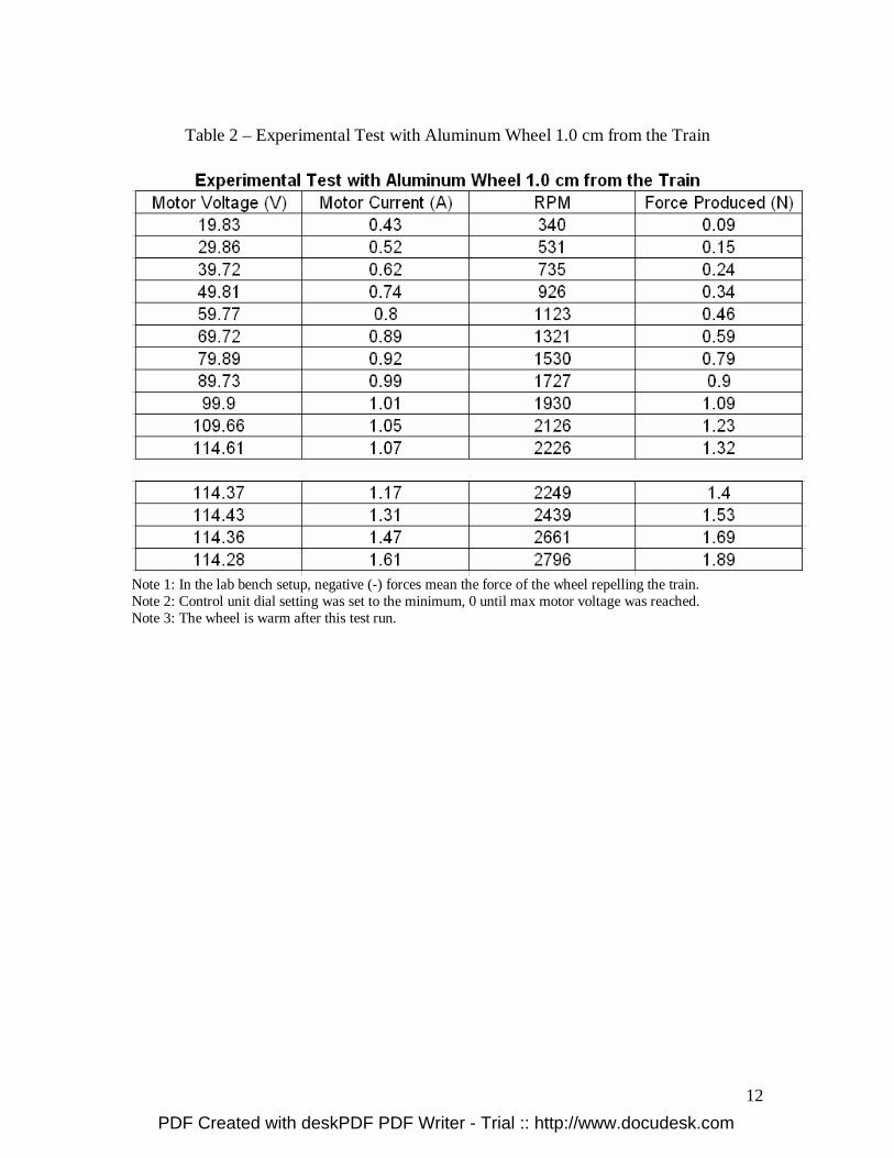
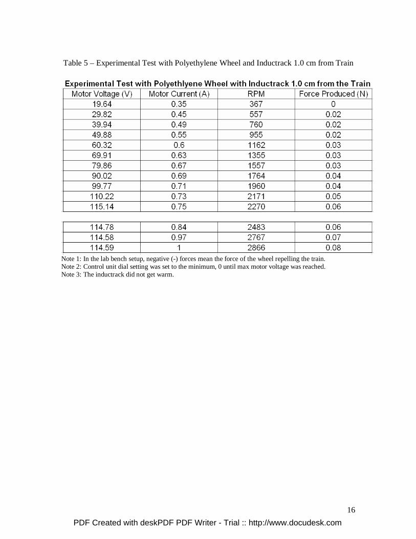
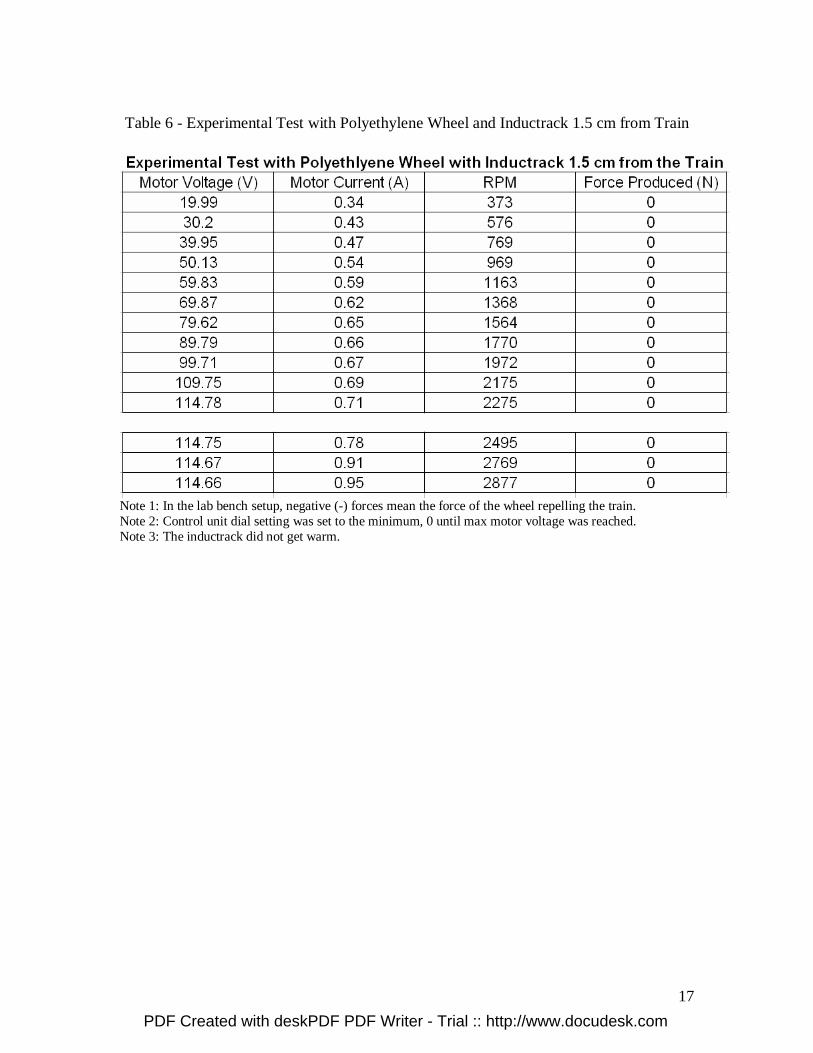
Table 2 – Experimental Test with Aluminum Wheel 1.0 cm from the Train ……………………………………………………….. 12 Table 3 – Experimental Test with Aluminum Wheel 1.5 cm from the Train ……………………………………………………….. 13 Figure 15 – 6 Inch Aluminum Drum Wheel Motor Voltage vs. Motor Current Results ………………………………………….. 14 Figure 16 – 6 Inch Aluminum Drum Wheel RPM vs. Force Generated Results ……………………………………………… 14 Table 4 – Experimental Test with Polyethylene Wheel and Inductrack 0.5 cm from the Train ……………………………… 15 Table 5 – Experimental Test with Polyethylene Wheel and Inductrack 1.0 cm from the Train ……………………………… 16 Table 6 – Experimental Test with Polyethylene Wheel and Inductrack 1.5 cm from the Train ……………………………… 17 Figure 17 – 6 Inch Polyethylene Wheel and Inductrack Motor Voltage vs. Motor Current Results …………………………….. 18 Figure 18 – 6 Inch Polyethylene Wheel and Inductrack RPM vs. Force Generated Results ……………………………………….. 18 Figure 19 – Graphical User Interface from Paul Friend in 2004 ..20 Table 7 – Standards/Requirements of Low-Speed Urban Maglev Program ………………………………………………………… 21 Table 8 – Standards/Requirements of Small Scale Train Maglev Program ………………………………………………………… 21
PDF Created with deskPDF PDF Writer - Trial :: http://www.docudesk.com

1
Project Summary: The goal of this project is to demonstrate Halbach array of magnets train levitation using a current generating rotary inductrack to create a magnetic force strong enough to levitate a small train. Thus the first goal is to demonstrate the generation of levitation force. Additional goals include using a position transducer to measure the displacement in height created by the train levitation and a digital force gauge to measure the force versus displacement. This project is a continuation of work done by Paul Friend, Tony Pederson, and Toby Miller in 2003-2004, as well as Dusty Funk and Kyle Getsla in 2005-2006. Inductrack Maglev Method: The method of train levitation using an inductrack was first introduced by Dr. Richard F. Post who first developed the inductrack in the late 1990’s at Lawrence Livermore National Laboratory. The inductrack method utilizes passive levitation so no external power is needed to levitate the train. The only power needed is to run the motor which turns the rotary inductrack for this application. Another benefit of the Inductrack method is that no complex controls are needed to safely levitate the train by the use of magnets since the levitation height is self-stabilizing. Block Diagrams and Subsystems: The overall system block diagram is shown in Figure 1.
Figure 1 – Overall System Block Diagram The Maglev System block above consists of a train consisting of a Halbach array of magnets, inductrack, rotary wheel, control unit, and DC motor. The overall system block diagram can be separated into two subsystems: one subsystem of a rotary wheel, DC motor, and control unit and one subsystem of levitation as described below.
PDF Created with deskPDF PDF Writer - Trial :: http://www.docudesk.com

2
The rotary subsystem block diagram is shown in Figure 2.
Figure 2 – Rotary Subsystem Block Diagram The rotary subsystem consists of DC power applied to a control unit which can vary the speed and torque of the DC motor. The DC motor is connected to the rotary wheel to accelerate the wheel to a specified angular velocity. The levitation subsystem block diagram is shown in Figure 3.
Figure 3 – Levitation Subsystem Block Diagram The levitation subsystem consists of the velocity of the wheel responsible for creating an induced current in the track, which in turn creates an induced magnetic force to levitate the train. The feedback path will consist of a levitation constant.
PDF Created with deskPDF PDF Writer - Trial :: http://www.docudesk.com

3
Halbach Array: The Halbach array is a special formation of magnets used to direct each individual magnet’s field to create a strong sinusoidal magnetic field below the array while nearly canceling the magnetic fields above the array. The standard 90 degree formation is shown in Figure 4.
Figure 4 – Standard Halbach Array Formation
The formation chosen for this project’s Maglev Train is the standard Halbach array formation as shown in Figure 4 consisting of five magnets parallel to another five magnets. Grade N38 nickel plated 12 mm cube magnets have been chosen to be used because of their high strength. Halbach Array Simulations: During previous research, a magnetic field simulation program called Vizimag was used to simulate the standard Halbach array formation [1]. The simulation results are shown in Figure 5.
PDF Created with deskPDF PDF Writer - Trial :: http://www.docudesk.com

4
Figure 5 – Simulated Halbach Array Train Fabrication: The fabricated train uses two Halbach arrays for levitation consisting of five grade N38 nickel plated magnets each. Balsa wood was the material chosen for the train construction because it is a lightweight, nonferrous material. The train was designed to match the curvature of a 6 inch wheel which was used for running experiments. Two trains were fabricated, one for measuring the generated forces against the train and the other for the displacement of the train due to levitation. Figure 6 shows the trains created with the Halbach arrays in it.
Figure 6 – Constructed Trains
PDF Created with deskPDF PDF Writer - Trial :: http://www.docudesk.com

5
Inductrack: The purpose of the Inductrack is to create a track that is an array of inductors. The inductors guide the induced current perpendicular to the direction of motion. The Inductrack must generate enough induced current to create a magnetic field with a great enough magnitude to levitate the train. The goal is to create as much inductance as possible with as low resistance as possible. This allows the train to begin levitating at a lower velocity due to a phase shift in the current. The inductrack method chosen for this project is laminated sheets, the same sheets that were used for last year’s project. The laminated sheets are thin sheets of laminated aluminum that has slots cut every 2.2 cm to guide induced currents. Previous research has indicated that the laminated sheet method creates the largest levitation forces at high velocities, but requires a higher velocity to levitate. The sheets create large drag forces compared to the levitation forces at low velocities. A small section of the inductrack that completes one current loop was separated and experimentally tested. It has a resistance of 0.5 mΩ and an inductance of 0.1 µH. Figure 7 shows the laminated sheets used as the inductrack in this project.
Figure 7 – Laminated Sheets Inductrack
PDF Created with deskPDF PDF Writer - Trial :: http://www.docudesk.com

6
Rotary Wheel: The rotary wheel used in last year’s project had problems in that the steel rivets on the spokes of the bicycle wheel were attracted to the magnets in the train. A picture of the bicycle wheel used is shown in Figure 8. The inductrack was wrapped around the bicycle wheel as Figure 9 shows. This was difficult to keep stable. Instead of trying to stabilize the bicycle wheel and inductrack, new wheel purchases and fabrications were researched.
Figure 8 – Bicycle Wheel
Figure 9 – Bicycle Wheel with Inductrack Purchasing a commercial wheel was researched. Larger wheels like wagon wheels have steel wrapped around the perimeter or metal screws keeping it together. Skyway Machine, Inc. in Redding, CA manufactures plastic bicycle wheels that were thought to be viable for a rotary wheel in this project. The problem is the peripheral is curved inside for the allowance of a bicycle tire. Outsourcing the fabrication of the wheel was also researched and Tri-Machine Products, Inc. in Peoria, IL was a viable solution. The cost of the material and labor was too expensive. The ideal case is to use a wheel with a large diameter so the RPM required for a specific tangential velocity is not as high as it would have to be with a smaller diameter wheel. Utilizing resources in the Power Lab, a 6 inch
PDF Created with deskPDF PDF Writer - Trial :: http://www.docudesk.com
7
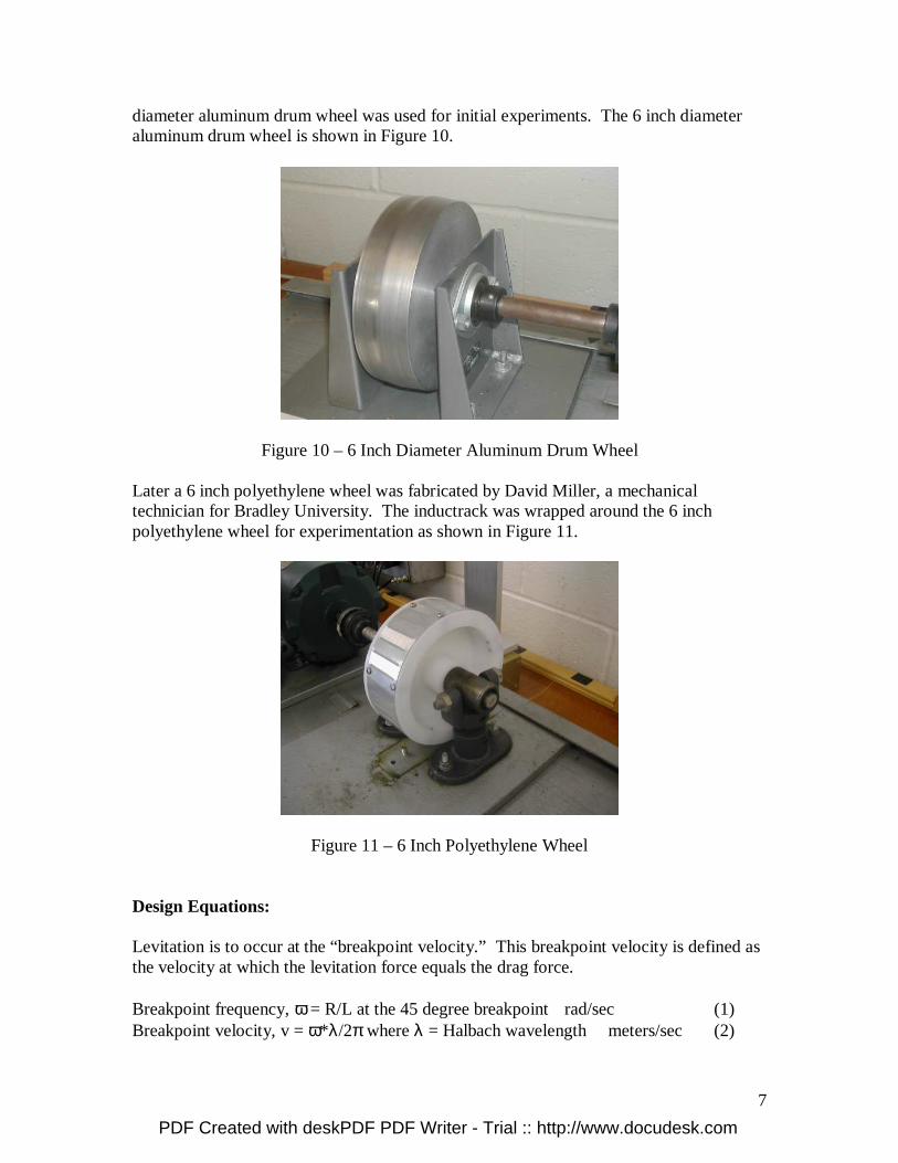
diameter aluminum drum wheel was used for initial experiments. The 6 inch diameter aluminum drum wheel is shown in Figure 10.
Figure 10 – 6 Inch Diameter Aluminum Drum Wheel
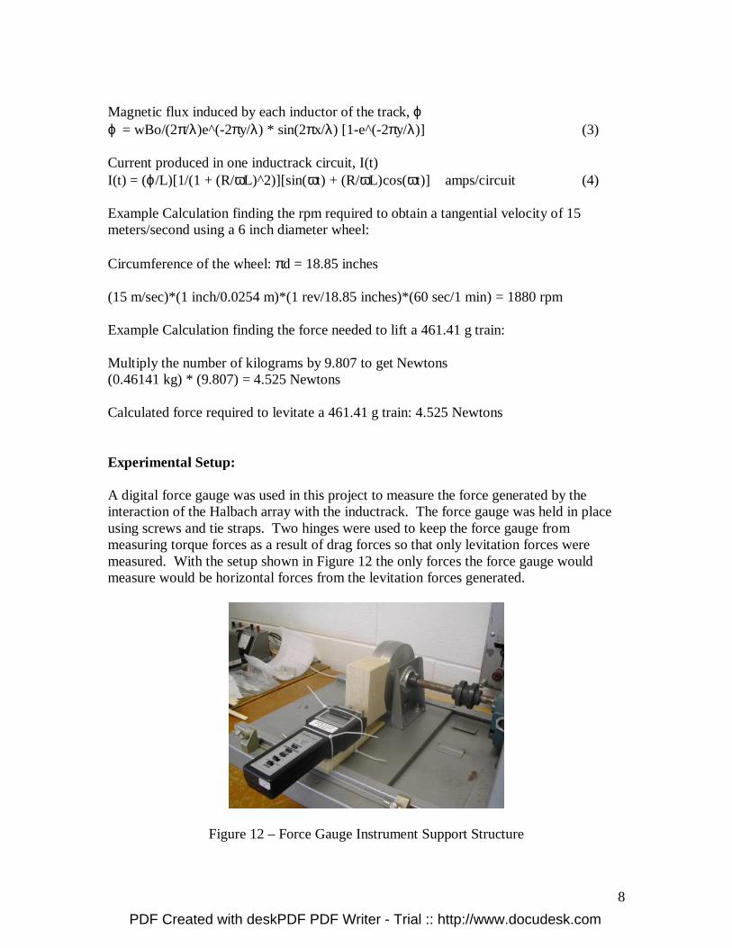
Later a 6 inch polyethylene wheel was fabricated by David Miller, a mechanical technician for Bradley University. The inductrack was wrapped around the 6 inch polyethylene wheel for experimentation as shown in Figure 11.
Figure 11 – 6 Inch Polyethylene Wheel
Design Equations: Levitation is to occur at the “breakpoint velocity.” This breakpoint velocity is defined as the velocity at which the levitation force equals the drag force. Breakpoint frequency, ω = R/L at the 45 degree breakpoint rad/sec (1) Breakpoint velocity, v = ω*λ/2π where λ = Halbach wavelength meters/sec (2)
PDF Created with deskPDF PDF Writer - Trial :: http://www.docudesk.com
8
Magnetic flux induced by each inductor of the track, ϕ ϕ = wBo/(2π/λ)e^(-2πy/λ) * sin(2πx/λ) [1-e^(-2πy/λ)] (3)
Current produced in one inductrack circuit, I(t) I(t) = (ϕ/L)[1/(1 + (R/ωL)^2)][sin(ωt) + (R/ωL)cos(ωt)] amps/circuit (4) Example Calculation finding the rpm required to obtain a tangential velocity of 15 meters/second using a 6 inch diameter wheel: Circumference of the wheel: πd = 18.85 inches (15 m/sec)*(1 inch/0.0254 m)*(1 rev/18.85 inches)*(60 sec/1 min) = 1880 rpm Example Calculation finding the force needed to lift a 461.41 g train:
Multiply the number of kilograms by 9.807 to get Newtons (0.46141 kg) * (9.807) = 4.525 Newtons Calculated force required to levitate a 461.41 g train: 4.525 Newtons Experimental Setup: A digital force gauge was used in this project to measure the force generated by the interaction of the Halbach array with the inductrack. The force gauge was held in place using screws and tie straps. Two hinges were used to keep the force gauge from measuring torque forces as a result of drag forces so that only levitation forces were measured. With the setup shown in Figure 12 the only forces the force gauge would measure would be horizontal forces from the levitation forces generated.
Figure 12 – Force Gauge Instrument Support Structure
PDF Created with deskPDF PDF Writer - Trial :: http://www.docudesk.com
9
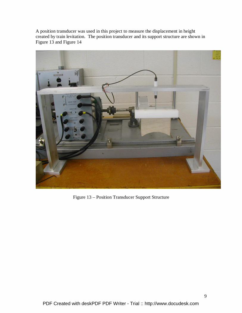
A position transducer was used in this project to measure the displacement in height created by train levitation. The position transducer and its support structure are shown in Figure 13 and Figure 14
Figure 13 – Position Transducer Support Structure
PDF Created with deskPDF PDF Writer - Trial :: http://www.docudesk.com

10
Figure 14 – Underside View of Position Transducer Support Structure Experimental Results: A series of three tests were done using the 6 inch aluminum drum wheel and three tests using the 6 inch polyethylene wheel with the inductrack. The experimental results include the motor voltage, motor current, rotational speed of the wheel, and levitation force produced. These measurements were done having the Halbach array of magnets on the train 0.5 cm from the wheel, 1.0 cm from the wheel, and 1.5 cm from the wheel. It was possible to run experiments on the 6 inch aluminum drum wheel because although it doesn’t have an inductrack wrapped around the perimeter, the aluminum wheel acts as an infinite number of current loops much like the current loop around each slot in the inductrack. One would expect larger forces to be generated with an infinite number of current loops than a finite number of current loops. It is much harder to analyze the aluminum drum wheel serving as an inductrack, but it proved to give interesting results.
PDF Created with deskPDF PDF Writer - Trial :: http://www.docudesk.com
11
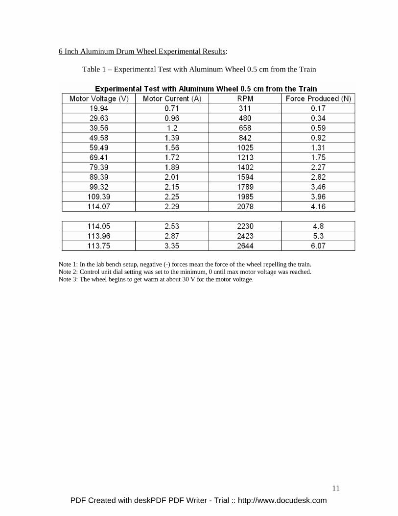
6 Inch Aluminum Drum Wheel Experimental Results:
Table 1 – Experimental Test with Aluminum Wheel 0.5 cm from the Train
Note 1: In the lab bench setup, negative (-) forces mean the force of the wheel repelling the train. Note 2: Control unit dial setting was set to the minimum, 0 until max motor voltage was reached. Note 3: The wheel begins to get warm at about 30 V for the motor voltage.
PDF Created with deskPDF PDF Writer - Trial :: http://www.docudesk.com
12
Table 2 – Experimental Test with Aluminum Wheel 1.0 cm from the Train
Note 1: In the lab bench setup, negative (-) forces mean the force of the wheel repelling the train. Note 2: Control unit dial setting was set to the minimum, 0 until max motor voltage was reached. Note 3: The wheel is warm after this test run.
PDF Created with deskPDF PDF Writer - Trial :: http://www.docudesk.com

13
Table 3 – Experimental Test with Aluminum Wheel 1.5 cm from the Train
Note 1: In the lab bench setup, negative (-) forces mean the force of the wheel repelling the train. Note 2: Control unit dial setting was set to the minimum, 0 until max motor voltage was reached. Note 3: The wheel is slightly warm after this test run.
PDF Created with deskPDF PDF Writer - Trial :: http://www.docudesk.com

14
Figure 15 – 6 Inch Aluminum Drum Wheel Motor Voltage vs. Motor Current Results
Figure 16– 6 Inch Aluminum Drum Wheel RPM vs. Force Generated Results
Motor Voltage vs. Motor Current
0
0.5
1
1.5
2
2.5
0 50 100 150
Motor Voltage (Volts)
Mo
tor
Cu
rren
t (A
mp
s)
Test 0.5 cm from the Train
Test 1.0 cm from the Train
Test 1.5 cm from the Train
RPM vs. Force Generated
0
0.5
1
1.5
2
2.5
3
3.5
4
4.5
0 500 1000 1500 2000 2500
RPM
Fo
rce
Gen
erat
ed (
New
ton
s)
Test 0.5 cm from the Train
Test 1.0 cm from the Train
Test 1.5 cm from the Train
PDF Created with deskPDF PDF Writer - Trial :: http://www.docudesk.com

15
Table 4 – Experimental Test with Polyethylene Wheel and Inductrack 0.5 cm from Train
Note 1: In the lab bench setup, negative (-) forces mean the force of the wheel repelling the train. Note 2: Control unit dial setting was set to the minimum, 0 until max motor voltage was reached. Note 3: The inductrack is slightly warm after this test run.
PDF Created with deskPDF PDF Writer - Trial :: http://www.docudesk.com
16
Table 5 – Experimental Test with Polyethylene Wheel and Inductrack 1.0 cm from Train
Note 1: In the lab bench setup, negative (-) forces mean the force of the wheel repelling the train. Note 2: Control unit dial setting was set to the minimum, 0 until max motor voltage was reached. Note 3: The inductrack did not get warm.
PDF Created with deskPDF PDF Writer - Trial :: http://www.docudesk.com
17
Table 6 - Experimental Test with Polyethylene Wheel and Inductrack 1.5 cm from Train
Note 1: In the lab bench setup, negative (-) forces mean the force of the wheel repelling the train. Note 2: Control unit dial setting was set to the minimum, 0 until max motor voltage was reached. Note 3: The inductrack did not get warm.
PDF Created with deskPDF PDF Writer - Trial :: http://www.docudesk.com
18
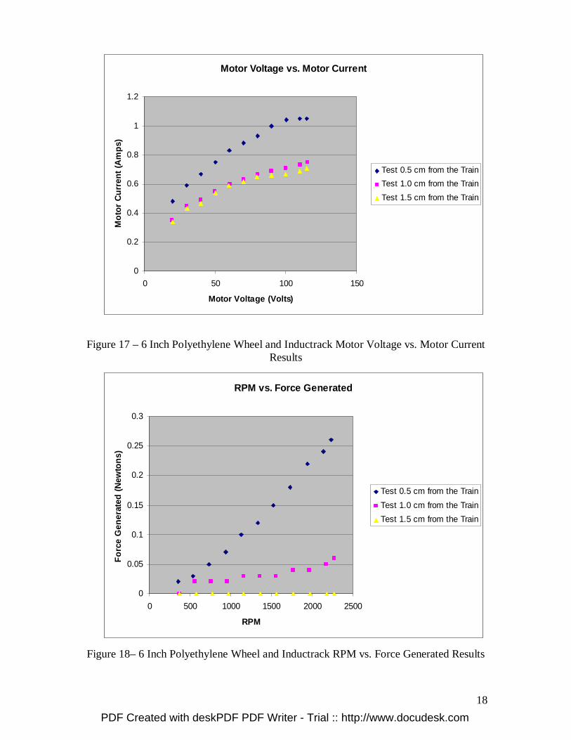
Figure 17 – 6 Inch Polyethylene Wheel and Inductrack Motor Voltage vs. Motor Current Results
Figure 18– 6 Inch Polyethylene Wheel and Inductrack RPM vs. Force Generated Results
Motor Voltage vs. Motor Current
0
0.2
0.4
0.6
0.8
1
1.2
0 50 100 150
Motor Voltage (Volts)
Mo
tor
Cu
rren
t (A
mp
s)
Test 0.5 cm from the Train
Test 1.0 cm from the Train
Test 1.5 cm from the Train
RPM vs. Force Generated
0
0.05
0.1
0.15
0.2
0.25
0.3
0 500 1000 1500 2000 2500
RPM
Fo
rce
Gen
erat
ed (
New
ton
s)
Test 0.5 cm from the Train
Test 1.0 cm from the Train
Test 1.5 cm from the Train
PDF Created with deskPDF PDF Writer - Trial :: http://www.docudesk.com
19
Discussion of Results: Taking a look at the experimental results from using the 6 inch aluminum drum wheel as the inductrack for the train, it is easy to see the effect the distance of the train from the wheel has on the system. Figure 15 clearly shows that with increased distance away from the wheel, the motor draws less current. The motor does not have to work as hard and less power is required the farther away the train is from the wheel. In Figure 17, the experimental results from using the 6 inch polyethylene wheel and inductrack provide similar results. Yet here, whether the train is 1.0 cm or 1.5 cm away from the inductrack the motor current produced are almost identical. This shows that the Halbach array of magnets is not effective in producing induced currents in the inductrack. When the train is 1.0 cm or farther from the inductrack, the effects of the Halbach array is negligible. This can also be seen in Figure 18. When the inductrack is 1.0 cm from the train very little levitation force is generated and no force is generated at 1.5 cm from the train. This matches the motor current behavior in Figure 17. When the inductrack is close enough to the train as in the 0.5 cm test, it is easy to see the Halbach array having an effect on the system. The Halbach array induces currents through the inductrack which thereby generate a magnetic force to produce levitation forces against the train. The force generated appears to be linear in nature according to Figure 18 but these are very small forces so it is hard to see a true trend. Figure 16 shows the force generated to be exponential in nature and this better matches the theory behind the Maglev system. Figure 19 shows the Graphical User Interface in Matlab created by Paul Friend in 2004. The teal line in the top plot shows the expected behavior of levitation forces as speed increases. It is exponential in nature until it reaches a certain velocity and then levels off. If it were possible to obtain more results on the aluminum drum wheel at higher speeds, this trend would most likely be observed. The red line in the top plot shows the theoretical drag forces produced at increasing speeds. The intersection of this red line with the teal line is the breakpoint velocity at which the levitation force equals the drag force. Although no measurements were taken on the drag force itself, its behavior can be seen by the behavior of the motor current. As previously discussed, the farther away the wheel is from the train, the less motor current is drawn. This is the same as saying less drag forces are produced. If high enough speeds were obtainable a plot of the motor current would behave just like the drag forces indicated as the red line in Figure 19. It would increase until it reached the breakpoint velocity and then steadily decrease until it leveled off.
PDF Created with deskPDF PDF Writer - Trial :: http://www.docudesk.com

20
Figure 19 - Graphical User Interface from Paul Friend in 2004 The results for the 6 inch aluminum drum wheel in Figure 16 prove the concept that more induced currents will produce a greater amount of force. Figure 16 shows much greater forces produced by the interaction of the Halbach array with the aluminum drum wheel than with the polyethylene wheel and inductrack. The aluminum drum wheel has a lower resistance than the inductrack, produces an infinite number of current loops and thus generates stronger levitation forces. Figure16 with the aluminum wheel test results shows 4.2 Newtons of force being generated at about 2200 rpm with the wheel being 0.5 cm from the train whereas Figure18 with the polyethylene wheel and inductrack shows about 0.26 Newtons. With these results, it is confident to say that more slots cut in the inductrack would prove to be helpful in generating stronger levitation forces. Ten to twenty slots per Halbach array wavelength would be ideal for further testing instead of the three for this current Maglev system. This Maglev system was trying to levitate 461.41 grams of weight which computed above is equal to 4.525 Newtons. Not quite 4.525 Newtons of levitation force was produced with this Maglev system so levitation was not seen. This is also due to the strong drag forces developed at lower velocities that prevented the train from moving up the two parallel rods. If the train is lifted manually up the rods and then let go it suspends about 0.5 cm above its resting height. This was measured with the naked eye, not the
PDF Created with deskPDF PDF Writer - Trial :: http://www.docudesk.com

21
position transducer. This “suspension” is due to the combination of levitation force produced and the drag force produced. The levitation force is close to the force needed to levitate the train, but not enough. When the train is lifted manually, the drag force is strong enough to “pull” the train around the track/wheel and since the vertical rods are there holding the train in place, the drag force pulls the train against one of the rods trying to pull the train around the wheel and it is kept suspended against the rod. At higher speeds the drag force would decrease and drop off and the levitation force would be high enough to levitate the train by itself. Specifications: A set of standards have been developed for a different project, the Low-Speed Urban Maglev Program. This project involves a real life-size train. The standards and requirements are shown in Table 7.
Table 7 - Standards/Requirements of Low-Speed Urban Maglev Program Max. Speed 160 km/hr Max Jerk 2.5 m/s3
Throughput 12000/hr/direction Inside Noise Level < 67 dB Max Acceleration 1.6 m/s2 DC Mag. Field in Car < 5 Gauss Min Curve Radius 18.3 m (60 ft.) Availability > 99.99% Max Grade 10% Ride Quality ISO 2631 (1987) These standards do not apply with a small scale train, but can be used to compare concepts. The small scale train, Halbach array of magnets, rotary wheel, and motor used in this project has the specifications as shown in Table 8.
Table 8 - Standards/Requirements of Small Scale Train Maglev Program Small Scale Train: Total Train Mass and Suspension Structure 0.46141 kg Force Required for Levitation 4.525 Newtons Halbach Array of Magnets: Magnet Strength 1.21 Tesla Magnet Thickness 0.012 meters Magnets Per Halbach Wavelength 4 Halbach Wavelength 0.055 meters Width of Halbach Array 0.06 meters Length of Halbach Array 0.06 meters Halbach Peak Strength 0.81281 Tesla Area Under Halbach Array 0.0036 m2 Rotary Wheel: Wheel Diameter 6 inches (0.1524 m) Wheel Circumference 18.85 inches (0.47879 m)
PDF Created with deskPDF PDF Writer - Trial :: http://www.docudesk.com

22
Inductrack Width 1.9488 inches (4.95 cm) Inductrack Inductor Size 0.0118 m x 0.051 m Inductrack Inductor Spacing 0.022 m Motor: Model Number Reliance 437698-KW Horsepower 1/3 Rated Speed 1725 rpm Rated Voltage 115 V Rated Current 3.4 A Max Ambient Temperature 40 degrees C Equipment Purchased: 20 - N38 Nickel Plated Cube Magnets $2.25/each 1 – Digital Force Gauge Model: 475040 $329.00/each 1 – Position Transducer Model: MLT002N3000B5C $234.36/each 1 - Balsa Wood Material $5.00/each 1 – 6” Polyethylene Material $28.00/each Total Cost of Project to Bradley University: $636.50 Note: Above prices do not include shipping or labor costs
PDF Created with deskPDF PDF Writer - Trial :: http://www.docudesk.com

23
Patents
Richard F. Post Magnetic Levitation System for Moving Objects U.S. Patent 5,722,326 March 3, 1998
Richard F. Post Inductrack Magnet Configuration U.S. Patent 6,633,217 B2 October 14, 2003
Richard F. Post Inductrack Configuration U.S. Patent 629,503 B2 October 7, 2003
Richard F. Post Laminated Track Design for Inductrack Maglev System U.S. Patent Pending US 2003/0112105 A1 June 19, 2003
Coffey; Howard T. Propulsion and stabilization for magnetically levitated vehicles U.S. Patent 5,222,436 June 29, 2003
Coffey; Howard T. Magnetic Levitation configuration incorporating levitation, guidance and linear synchronous motor U.S. Patent 5,253,592 October 19, 1993 Levi;Enrico; Zabar;Zivan; Air cored, linear induction motor for magnetically levitated systems U.S. Patent 5,270,593 November 10, 1992 Lamb; Karl J. ; Merrill; Toby ; Gossage; Scott D. ; Sparks; Michael T. ;Barrett; Michael S. U.S. Patent 6,510,799 January 28, 2003
PDF Created with deskPDF PDF Writer - Trial :: http://www.docudesk.com

24
Acknowledgements
Dr. Winfred Anakwa - project advisor Mr. Steven Gutschlag - project advisor Mr. Christopher Mattus - parts coordinator Mr. Nick Schmidt - assistance with various parts of the train and structure fabrication Mr. David Miller - assistance with various parts of the train, wheel, and structure fabrication Robert Ruber - assistance with motor research Sam Gurol and Bob Baldi - previous research Richard F. Post - previous research Paul Friend - previous research Dusty Funk & Kyle Getsla - previous research
PDF Created with deskPDF PDF Writer - Trial :: http://www.docudesk.com

25
Bibliography
[1] Paul Friend’s Senior Project Magnetic Levitation Technology 1 Final Report, 12
May, 2004. [2] Paul Friend’s Senior Project Proposal, 12 December, 2003. [3] Paul Friend’s Project Proposal Presentation, 9 December, 2003. [4] Dusty Funk & Kyle Getsla’s Senior Project Magnetic Levitation Train Final Report,
2005. [5] Halbach, K., “Applications of permanent magnets in accelerators and electron
storage rings,” Journal of Applied Physics, vol. 57, p. 3605, 1985. [6] Post, Richard F., Ryutov, Dmitri D., “The Inductrack Approach to Magnetic
Levitation,” Lawrence Livermore National Laboratory.
PDF Created with deskPDF PDF Writer - Trial :: http://www.docudesk.com