toward more efficient transport: the inductrack maglev...
TRANSCRIPT
Toward More Efficient Transport: The Inductrack Maglev System
Advanced Transportation WorkshopStanford Global Climate and Energy Project
10 October 2005
Presented by:Richard F. Post
Lawrence Livermore National Laboratory
There are many reasons why magnetically levitated trains could be preferred over conventional transit systems
• Inter-city transportation: Much higher speeds than are possible with steel-wheeled trains, lower noise, greater passenger comfort, increased safety against mechanical failures, reduced maintenance.
• Relative to aircraft: Higher energy efficiency, safer, less weather-dependent, and would permit in-city departure and arrival.
• Urban transit systems: Lower noise, much lower maintenance, greater rider comfort, can climb steeper grades, higher energy efficiency than conventional urban transit systems.
GCEP-02
Two different types of Maglev trains have been built and demonstrated at full scale at speeds up to 500 km/hr
• Magnetic attraction - EMS (Electro-Magnetic Suspension) systems, using servo-controlled electromagnets on the train car, attracted upward to a iron-plate rail.
• Magnetic repulsion -EDS (Electro-Dynamic Suspension) systems, using cryogenically cooled superconducting magnets on the moving car, repelled by currents induced in coils embedded in “tracks” on each side of the train.
• Example EMS system: The German Trans-Rapid TR08 demonstration train and 30 kilometer test track, with operating speeds up to 450 km/hr.
• Example EDS system: The Japanese Yamanashi demonstration train, with speeds of 500 km/hr on a 18 kilometertest track.
GCEP-03
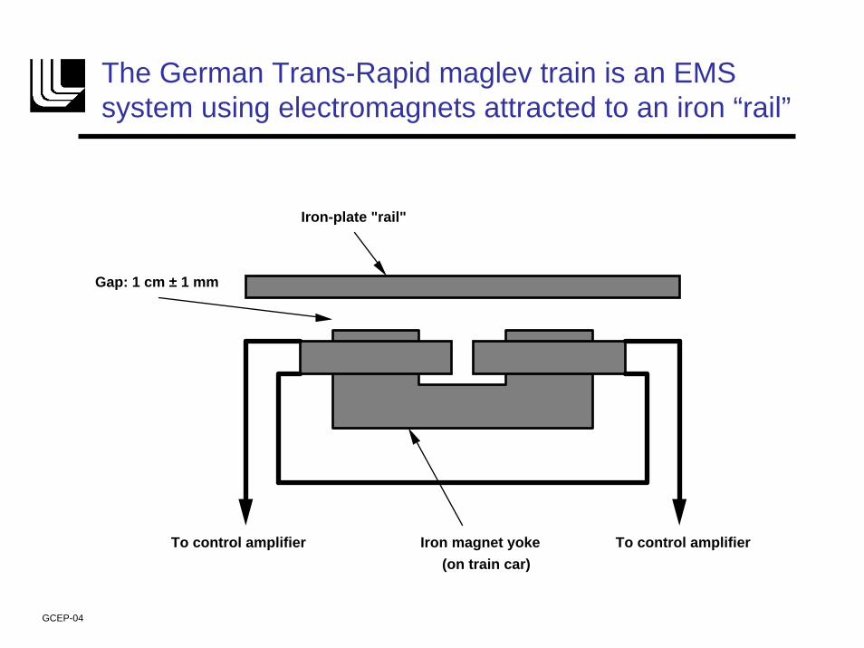
The German Trans-Rapid maglev train is an EMS system using electromagnets attracted to an iron “rail”
Gap: 1 cm ± 1 mm
Iron-plate "rail"
Iron magnet yokeTo control amplifier To control amplifier(on train car)
GCEP-04
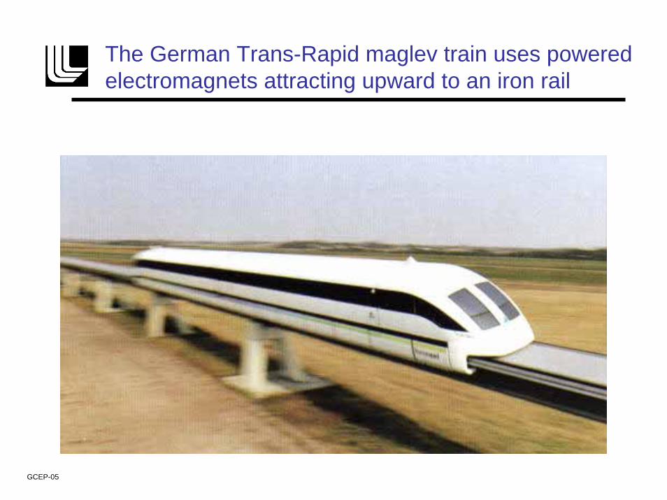
The German Trans-Rapid maglev train uses powered electromagnets attracting upward to an iron rail
GCEP-05
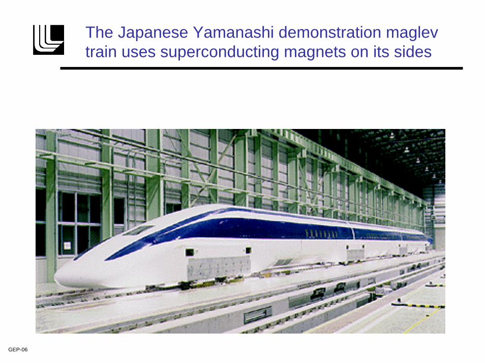
The Japanese Yamanashi demonstration maglevtrain uses superconducting magnets on its sides
GEP-06
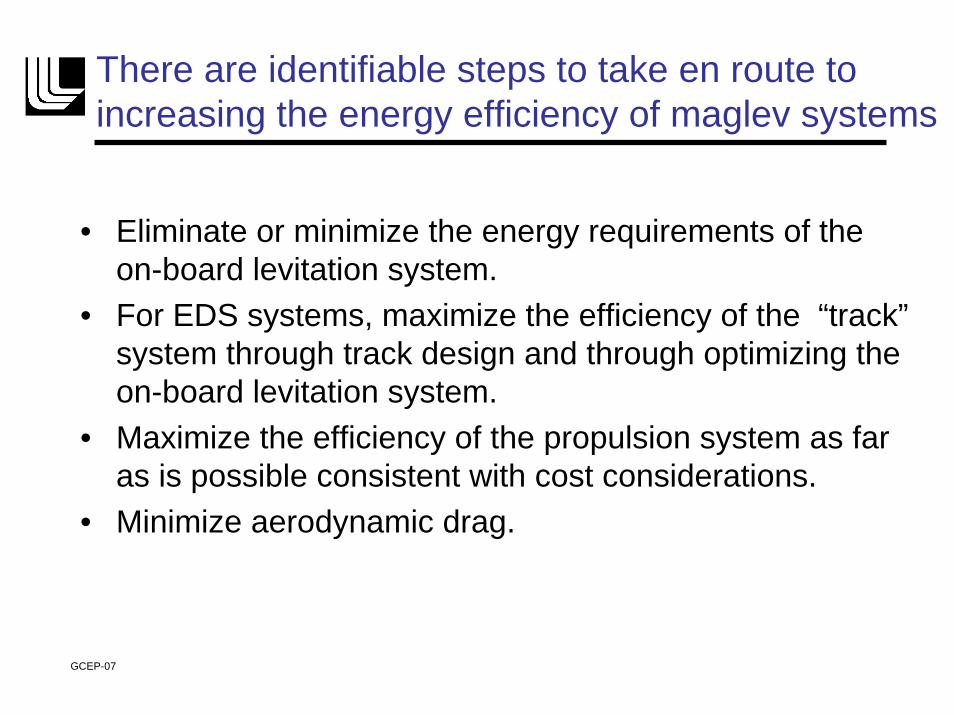
There are identifiable steps to take en route to increasing the energy efficiency of maglev systems
• Eliminate or minimize the energy requirements of the on-board levitation system.
• For EDS systems, maximize the efficiency of the “track”system through track design and through optimizing the on-board levitation system.
• Maximize the efficiency of the propulsion system as far as is possible consistent with cost considerations.
• Minimize aerodynamic drag.
GCEP-07
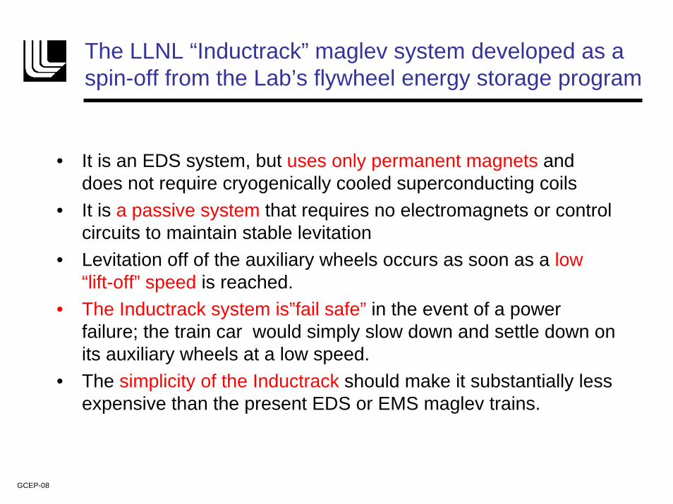
The LLNL “Inductrack” maglev system developed as a spin-off from the Lab’s flywheel energy storage program
• It is an EDS system, but uses only permanent magnets and does not require cryogenically cooled superconducting coils
• It is a passive system that requires no electromagnets or control circuits to maintain stable levitation
• Levitation off of the auxiliary wheels occurs as soon as a low “lift-off” speed is reached.
• The Inductrack system is”fail safe” in the event of a power failure; the train car would simply slow down and settle down on its auxiliary wheels at a low speed.
• The simplicity of the Inductrack should make it substantially less expensive than the present EDS or EMS maglev trains.
GCEP-08
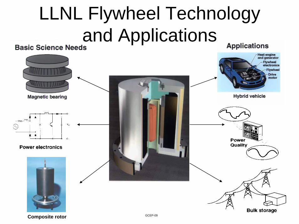
LLNL Flywheel Technology and Applications
Integrated System
Composite rotor GCEP-09
The Inductrack system optimizes levitation efficiency, using permanent magnets and a passive “track.”
• Special arrays (Halbach arrays) of permanent magnets are employed, mounted on “bogies”underneath the car.
• The periodic magnetic fields from the magnet arrays on the moving train car induce currents in a close-packed array of shorted electrical coils in the “track”to produce levitation (above a low “transition” speed).
GCEP-10
In the 1980’s Klaus Halbach came up with better ways to employ permanent magnets in focusing particle beams
• The Halbach array makes optimal use of permanent-magnet material by concentrating the field on the front face of the array, while nearly canceling the field on the back face of the array
• The magnetic field near the front face of the array varies sinusoidally with position parallel to the face of the array, and falls off exponentially with distance away from the front face.
• Only permanent-magnet material is employed in Halbach arrays; no “back iron”elements or iron poles are needed.
GCEP-11
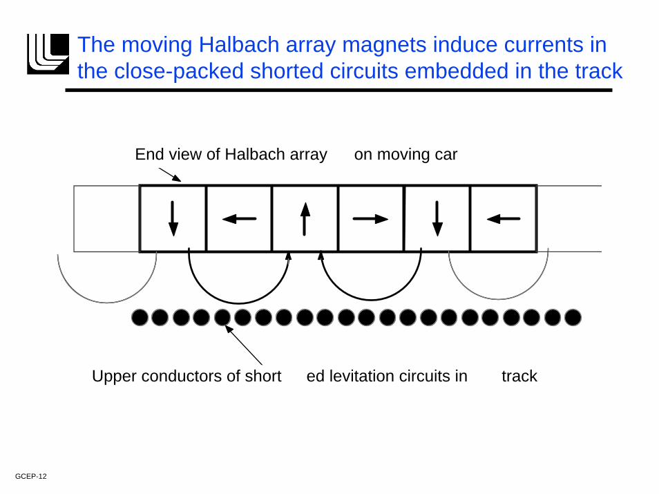
The moving Halbach array magnets induce currents in the close-packed shorted circuits embedded in the track
End view of Halbach array on moving car
Upper conductors of short ed levitation circuits in track
GCEP-12
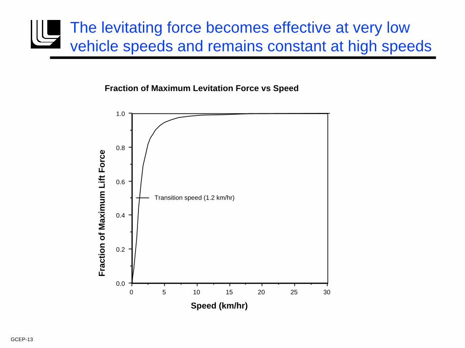
The levitating force becomes effective at very low vehicle speeds and remains constant at high speeds
0 5 10 15 20 25 300.0
0.2
0.4
0.6
0.8
1.0
Fraction of Maximum Levitation Force vs Speed
Speed (km/hr)
Frac
tion
of M
axim
um L
ift F
orce
Transition speed (1.2 km/hr)
GCEP-13
The Laboratory is a member of a team that is designing an urban maglev system employing the Inductrack approach.
• The team (which also includes several engineering firms in the Pittsburgh, Penn. area), was organized by General Atomics (San Diego) and is funded by the Federal Transit Administration.
• The advantages of maglev in urban settings (relative to conventional urban rail systems) include: Lower noise, lower maintenance, higher efficiency, higher grade and tighter turn capabilities (allowing operation on elevated tracks that can accommodate to an urban environment without the need for underground-tunnel operation).
• Better to satisfy urban (moderate speed) applications we have developed the Inductrack II configuration, which greatly reduces electromagnetic drag forces at urban speeds (relative to Inductrack I, which is an alternative for high-speed applications).
GCEP-14
The Inductrack II maglev employs dual Halbach arrays, reducing drag losses and enhancing levitation forces
• A cantilevered ladder track is used, interacting with two facingHalbach arrays, one above, and one below the track.
• The horizontal component of the magnetic fields from the upper and lower Halbach arrays are additive, while the vertical field of the lower array opposes that of the upper array.
• By adjusting the thickness or the width of the magnets of the lower array relative to the upper array an optimum level of induced levitating current can be achieved for a given levitated weight and magnet weight.
• Either a litz-cable “ladder track” or slotted, laminated, sheet conductors with fiber composite reinforcement could be used to construct the cantilevered track.
GCEP-15
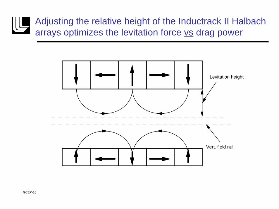
Adjusting the relative height of the Inductrack II Halbacharrays optimizes the levitation force vs drag power
Vert. field null
Levitation height
GCEP-16
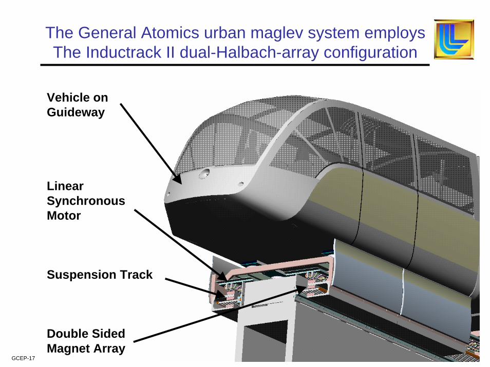
The General Atomics urban maglev system employsThe Inductrack II dual-Halbach-array configuration
Vehicle on Guideway
Linear Synchronous Motor
Suspension Track
Double Sided Magnet Array
GCEP-17
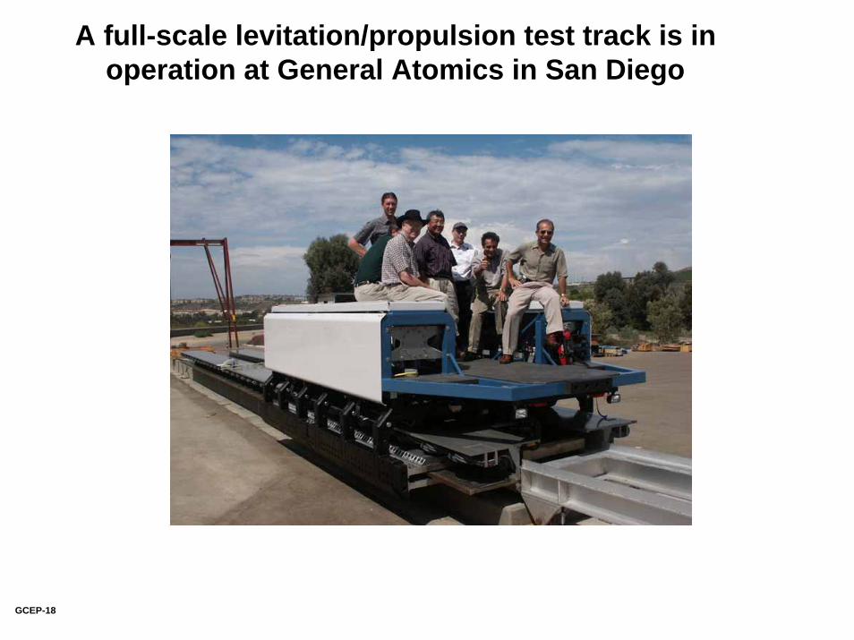
A full-scale levitation/propulsion test track is inoperation at General Atomics in San Diego
GCEP-18
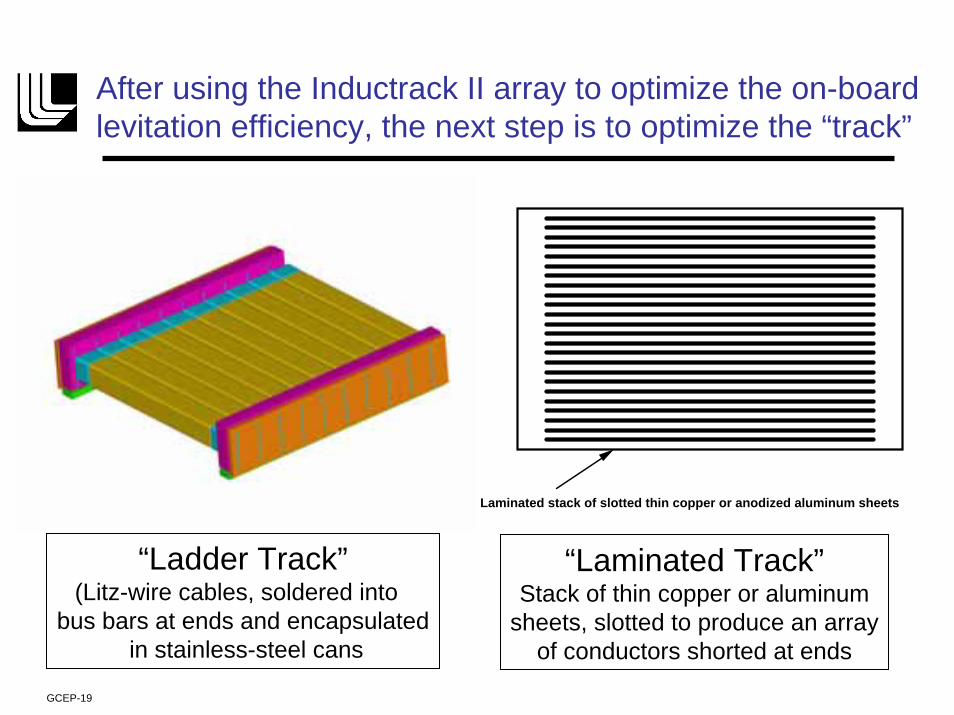
After using the Inductrack II array to optimize the on-board levitation efficiency, the next step is to optimize the “track”
Laminated stack of slotted thin copper or anodized aluminum sheets
“Ladder Track”(Litz-wire cables, soldered into
bus bars at ends and encapsulatedin stainless-steel cans
“Laminated Track”Stack of thin copper or aluminum
sheets, slotted to produce an arrayof conductors shorted at ends
GCEP-19
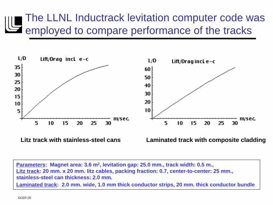
The LLNL Inductrack levitation computer code was employed to compare performance of the tracks
Litz track with stainless-steel cans Laminated track with composite cladding
Parameters: Magnet area: 3.6 m2, levitation gap: 25.0 mm., track width: 0.5 m., Litz track: 20 mm. x 20 mm. litz cables, packing fraction: 0.7, center-to-center: 25 mm.,stainless-steel can thickness: 2.0 mm.Laminated track: 2.0 mm. wide, 1.0 mm thick conductor strips, 20 mm. thick conductor bundle
GCEP-20
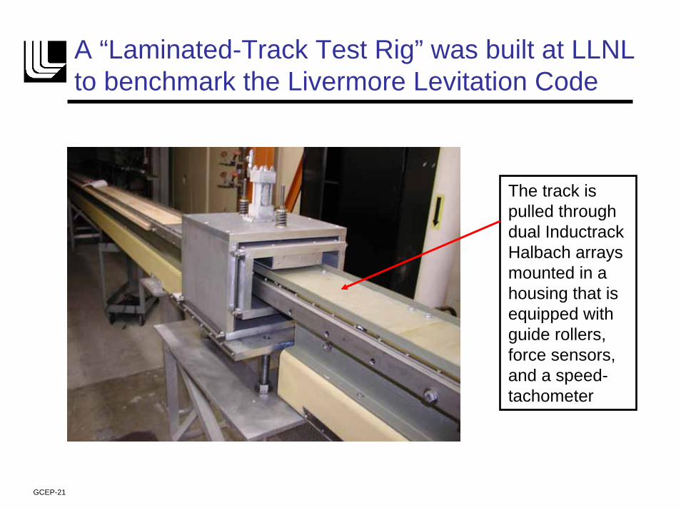
A “Laminated-Track Test Rig” was built at LLNL to benchmark the Livermore Levitation Code
The track ispulled throughdual InductrackHalbach arraysmounted in a housing that isequipped withguide rollers,force sensors,and a speed-tachometer
GCEP-21
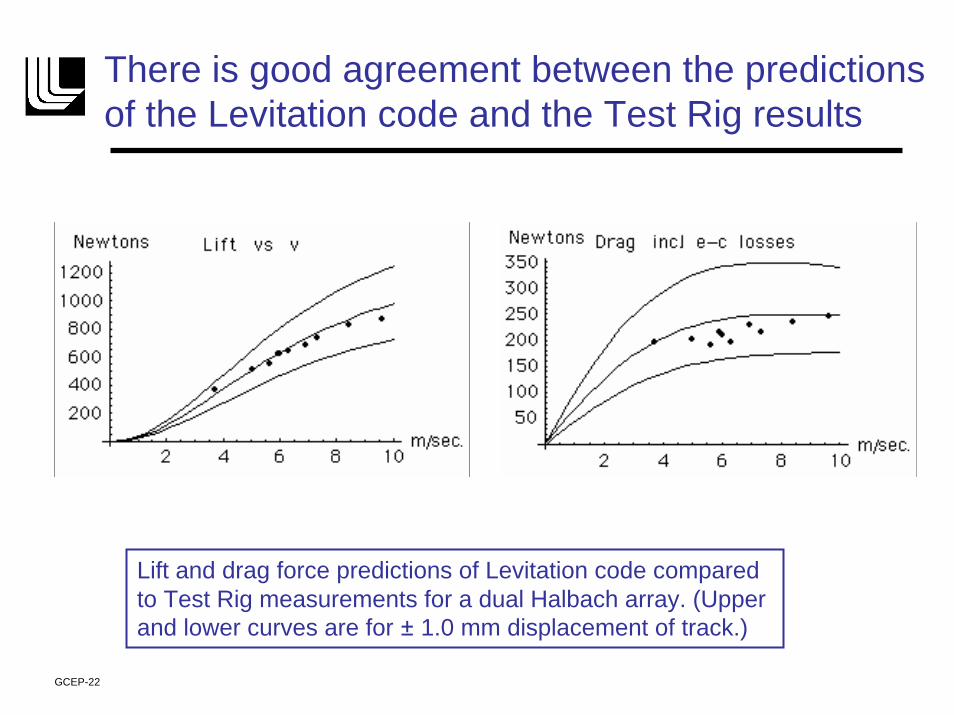
There is good agreement between the predictions of the Levitation code and the Test Rig results
Lift and drag force predictions of Levitation code comparedto Test Rig measurements for a dual Halbach array. (Upper and lower curves are for ± 1.0 mm displacement of track.)
GCEP-22
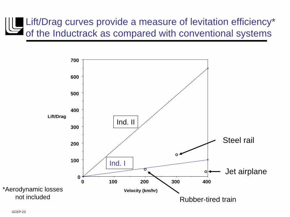
Lift/Drag curves provide a measure of levitation efficiency*of the Inductrack as compared with conventional systems
0 100 200 300 4000
100
200
300
400
500
600
700
Velocity (km/hr)
Lift/Drag
Jet airplane
°
Steel rail
°
Rubber-tired train
Ind. II
Ind. I °
*Aerodynamic lossesnot included
GCEP-23
maximizing maglev energy efficiency requires both high levitation efficiency and high propulsion efficiencymaximizing maglev energy efficiency requires both high levitation efficiency and high propulsion efficiency
• Maglev systems such as the G-A Inductrack urban maglev system and the Japanese HSST employ linear synchronous motors (LSMs) for propulsion.
• LSMs operate by using inverters to drive high ac currents through 3-phase windings embedded in the track.
• To keep the resistive energy losses within acceptable bounds, the “block length” of these windings must be limited, using “block switches,” adding to the cost and complexity of the system.
• In connection with a NASA-sponsored study at LLNL of the rocket-launching capabilities of Inductrack, Ed Cook of the Laboratory has developed a modular pulsed LSM drive that promises much higher efficiency than that possible with conventional LSM drive systems.
GCEP-24
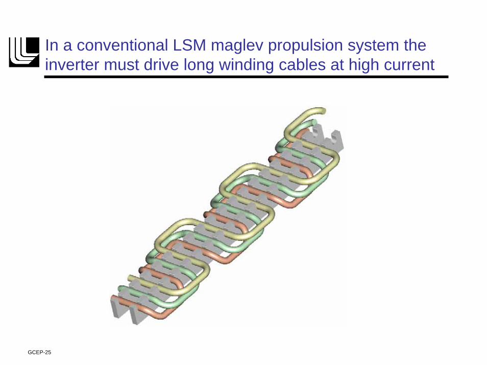
In a conventional LSM maglev propulsion system the inverter must drive long winding cables at high current
GCEP-25
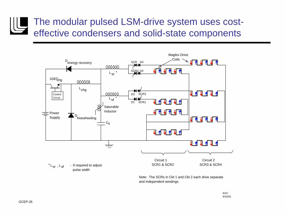
The modular pulsed LSM-drive system uses cost-effective condensers and solid-state components
SCR1
SCR3
SCR2
SCR
D1
D3
D2
D4
Lsr
sfL
Cs
Lchg
Dfreewheeling
IGBTchg
Power Supply
Saturable Inductor
Circuit 1 SCR1 & SCR2
Circuit 2 SCR3 & SCR4
D energy recovery
Control Circuit
Note: The SCRs in Ckt 1 and Ckt 2 each drive separate and independent windings
- if required to adjust pulse width
Lsr sfL,
*
*
*
Maglev Drive Coils
EGC 9/10/01
GCEP-26
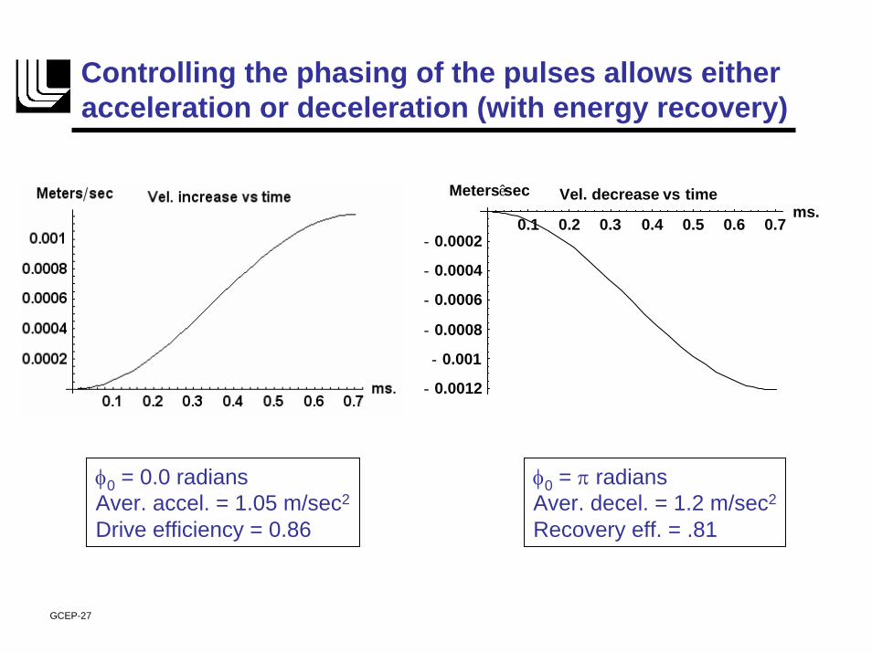
Controlling the phasing of the pulses allows either acceleration or deceleration (with energy recovery)
0.1 0.2 0.3 0.4 0.5 0.6 0.7ms.
- 0.0012
- 0.001
- 0.0008
- 0.0006
- 0.0004
- 0.0002
Metersêsec Vel. decrease vs time
φ0 = 0.0 radiansAver. accel. = 1.05 m/sec2
Drive efficiency = 0.86
φ0 = π radiansAver. decel. = 1.2 m/sec2
Recovery eff. = .81
GCEP-27
Summary and Conclusions• Urban and inter-city maglev systems could represent a practical and energy-
efficient solution to pressing transit needs.• To maximize the energy efficiency of maglev systems both the levitation
means and the propulsion system must be optimized.• A candidate system is the Inductrack, employing permanent magnets on the
moving vehicle to achieve levitation.• Based on analytic theory and benchmarked computer codes optimized
design parameters for urban and inter-city Inductrack transit systems have been presented.
• A generic urban version of the Inductrack is under development by General Atomics in San Diego, en route to its deployment and use in a public transit system in Pennsylvania.
• Other applications of the Inductrack concept have been considered, such as “people movers,” and efficient and speedy inter-city transport of high-value (Fed-Ex-like) freight in evacuated tubes.
GCEP-28