improvements in radio receivers - philips bound... · two important improvements in radio...
TRANSCRIPT
264 PHILlPS TECHNICAL REVIEW Vol. 1, No. 9
IMPROVEMENTS IN RADIO RECEIVERS
By C. J. VAN LOON.
Summary. Two important improvements in radio receivers, viz., touch tuning and low-frequency counter-coupling, are discussed in detail. "
In touch tuning sharp tuning is indicated by the turning of the tuning knob suddenlybecoming stiffer; in the circuit employed a braking magnet which brakes the tuning-knobshaft is magnetised on.sharp tuning. This device has been supplemented by an arrangement,~hich by mechanical means keeps the sèt perfectlysilent as long as no station has beensharply tuned in.With low-frequency counter-coupling the distortion occurring in low-frequency ampli-
fication is reduced to a small fraction of its value in the absence of counter-coupling,the 'frequency relationship of amplification being favourably influenced at the same time.
Introduetion
I,
·The most important characteristics of radioreceivers are unquestionably their purity of repro-duction, their selectivity and their sensitivity. Inthe course of the technical development of receivingsets the quality of reproduetion -has been improvedin various directions, thus the acoustic reproduetionof the loudspeaker, which during the first fewyears of broadcasting was limited to a comparativelynarrow range of audio-frequencies, has steadilybeen improved" upon such that a range of forinstance 40 to 10 000 cycles/sec. .can now be re-produced with satisfactory uniformity. Further-more, .the technical design and construction of'tbe 'various 'amplifying stages in a receiver and theoutputs of the amplifying and output valves havebeen raised- to a high stage of development, theseadvallces being naturally also to the markedadvantage of purity of reproduction.
,.•
Controllable Band Width
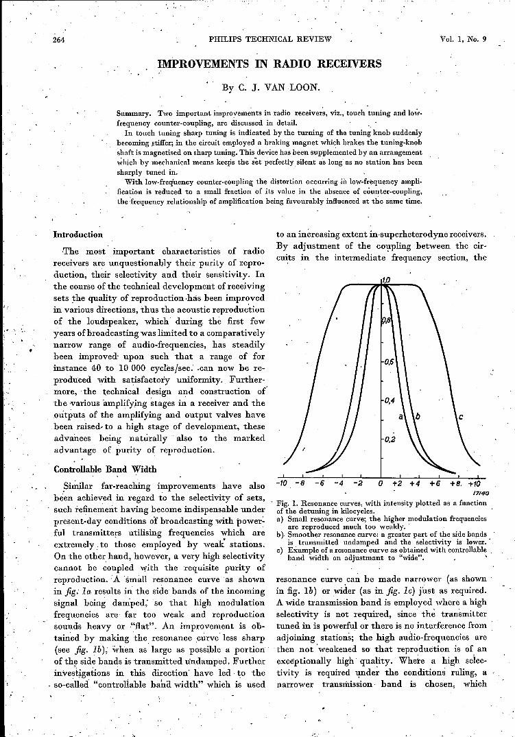
_S~:ilar far-reaching improvements have alsobeen achieved in regard to the selectivity of sets,such refine~e:rit having become indispensable underpresent-day conditions of broadcasting with 'power:ful transmitters utilising frequencies which areextremely to ~hose employed by weak stations.On the other hand, however, a very high selectivitycannot he coupled with the requisite purity ofreproduction. :A 'small resonance curve as shownin fig: I a results ill the side bands of the incomingsignal being damped; so that high modulationfrequencies are far too weak and reproduetion. sounds heavy or ·"flat". An' improvement is ob-tained by making the resonance _curve less sharp(see fig. lb); when as 'large as possible a portionof the side bands is transmitted undamped. Furtherinvestigations in this direction have led to the
. so-c~lleci "controllable baha width" which is used
to an increasing extent in-superheterodyne receivers.By adjustment of the coupling between the cir-cuits in the intermediate frequency section, the
-ta -8 -6 -4 -2 a/7/40
. Fig. 1. Resonance curves, with intensity plotted as a functionof the detuning in kilocycles.a) Small resonance curve; the higher modulation frequencies
are reproduced much too weakly.b) Smoother resonance curve: a greater part of the side bands
is . transmitted undamped and the selectivity is lower..c) Example of a resonance curve as obtained with controllable,
band width on adjustmant to "wide". '
resonance curve. can be made narrower (as shownin fig. lb) or wider (as in fig. le) fust as required.A wide transmission band is employed where a highselectivity is not required, since thè transmittertuned in is powerful or there is no interference fromadjoining stations; the high audio-frequencies arethen not 'weakened so that reproduetion is of anexceptionally high quality. Whete a high seiec-tivity is required under the conditions ruling, anarrower transmission band is chosen, which
..SE:PTEMBER 1936 IMPROVEMENTS IN RADIO RECEIVERS 265
however unavoidably leads to a loss of the high _ tained when sharp, tuning was attained so thatnotes. tuning was again an audible process. In this Iabor-
atory an entirely new method of tuning has how-ever been developed, viz., a .method of "touch"tuning, which considerably facilitates accurateadjustment. Sharp tuning is. here indicated by 'ásudden braking of ,the tuning knob, being achievedby means of a circuit in which as sharp tuning isapproached there is a sudden increase in currentwhich is utilised to hold the tuning shaft by meansof a magnet. An arrangement can also b~ quiteeasily incorporated with this circuit which by mech-anical means keeps the receiver completely silentuntil it has been sharply tuned to the station(socalled "silent" tuning); as soon as the brakingmagnet is energised- a contact is closed at the sametime which connects up the loudspeaker system.Iri this ~\ray "touch" tuning is combined with"silent" tuning.We shall discuss the operation of the "touch"
, tuning circuit with, the aid of a number of-diagrams.Assume that the receiving set which has to beequipped with - the "touch" tuning system is aheterodyne receiver of the type shown diagram-matically ill fig. 2.
When the set. is sharply tuned the high-frequencyportion is adjusted to the frequency of the' in-coming signal and at the same time the oscillatortuned to a frequency such that the differential'frcquency generated in the mixer valve is exactlyequal -to the intermediate frequency fo to whichthe intermediate-frequency portion is tuned.On a slight ,departure from the sharp-tuningposition by giving the tuning knob a little turn,the oscillator hecomes' detuned. The differentialfrequency has thus been altered. and no longercoincides with the intermediate frequency. The, cir-cuits in the high-frequency portion are also detuned,so that in consequence there is a slight change in theamplitude of the signal passed to ,the mixer valve.If detuning is not excessive, then owing to theoperation of the automatic volume control it maybe expected that to a first approximation a signalwhose frequency varies 'while the amplitude remainssubstantially the same will he obtained at ,th«: out-put of the intermediate-frequency amplifier, i.e.,at P; on sharp tuning the frequency, is exactly.equal to the intermediate 'frequency Jo. '. .. The circuit shown in jig. 3 is now connected toP through a small, condenser Cl' This arrangementconsists of a circuit (L C r) which is tuned to theintermediate frequency fo. The oscillating alter-nating voltage in this circuit is rectified by .thediode D,' so that a direct voltage is obt~ined at
Automatic Volume Control
An improvement which has been incorporated. in a large number of radio-receiving sets forseveral years is the automatic control of volume,consisting in producing an: automatic dècrease inthe amplification of a set as the signal at thedetector becomes ~ore· powerful. The 'markeddifferences between the input signal voltages(a, medium-strength signal, for instance, gives'
, 0.1 millivolt in the aerial, and the signal' from apowerful local station, 500 millivolts) are reducedconsiderably in the set itself by the automatic'volume control., The pronounced advantages "ofautomatic volumecontrol both as regards fluctuations in the strengthof the station tuned in (fading effects) and whenlistening in to a' number of stations of differentoutputs in succession, are too well known to requiredetailed discussion. Such control, however, introd-uces a number of difficulties; for instance it is moredifficult with an A.V.C. to determine sharp tuningof a station. In receiving sets without automaticvolume control sharp tuning presents no difficulty,for tuning by ear· is merely continued until amaximum volume of reception is obtained. On theother hand; accurate, audio-tuning is much moredifficult in those sets equipped with automaticvolume. control and also having a resonancecurve with a flat peak; on slight detuning of theset there is no detectible difference in volume
, ,control compensates for anysince automatic
reduction.It thus' becomes necessary to employ as a cri-
terion of correct tuning a maximum ~olumê of theiow notes or a minimlim of distortion. This methodof tuning requires, however, considerable skillwith the result a set of this type is frequentlyflat tuned, thus affecting the purity of reproduetionowing to the absence of the low notes and theoccurrence of distortion.
"Touch" Tuning
It is not surprising, therefore, that means havesought to eliminate these difficulties and whichwould indicate in a simple manner when sharptuning was realised. One method evolved for thispurpose was that of "visual" tuning in which,.a maximum or minimum deflection of a pointerwas obtained Iwhen tuning was sharp. Circuitswere also evolved with which" as in early receivingsets, a fairly definite maximum volume was ob-
-.

266 PHILIPS TECHNICAL REVIEW Vol. I, N,o.'9
H.I~.. . Mixer valve I.F. Detector, L.F. Loudspeaker
Oscillator Tuning-knob
Fig. 2. Circuit of a super-heterodyne receiver. The intermediate-frequency signal fortouch tuning is tapped from the point P.
the resistance R, which is by-passed by thecondenser C2• R is also connected in series with'a direct-current source VB whose negative pole.
, L
r
Fig. 3. Equivalent .circuit for "touch" tuning. On sharptuning of the set a voltage is obtained at P (see also fig. 2)which is passed through Cl to the oscillating circuit [.Crtuned to the intermediate frequency; on sharp tuning thevoltage in this circuit is greater than VB so that the diodeDwith which the threshold voltage VB is connected in seriesacts as a rectifier and furnishes a direct voltage at the resist-ance R which serves for operating a braking arrangement.As detuning becomes greater the voltage in' circuit LCrbecome smaller, so that from a certain degree of detuningVB prevents rectification and the brake no longer operates.
is connected to the anode, so that in the absenceof alternating voltage in the, circuit -the anode ofthe diode ~s negative with respect to the cathode.It should he noted that a rectified' current onlycommences to flow when' the amplitude 'of thealternating voltage is greater than the thresholdvoltage VB'
When the. receiver is sharply tuned' 'pole P, as
we have seen, will have a voltage with the frequencyJo', The voltage resulting therefrom in the oscillatingcircuit will have an amplitude VOo On slight de-tuning the amplitude of the voltage in P willre~ain' practically unchanged. If the' frequencyis altered to 10 + LII (or 10 - LII) the circuitvoltage will then drop to:
If Vo> VB the diode will pass current at tuningand a direct voltage will be produced at R. Ondetuning this current ceases to flow as soon as LIIreaches a limiting value LIIUrn as expressed by theequation:
1, VB ... (1).
Vo 1/ (4 'TC LII urn) 2
1+ . ril:
Thus by a suitable choice of the thl'eshold'voltage VB it is possible to determine in whatfrequency range on both sides of the resonancefrequency 10 rectificatiou will occur and a directvoltagé be obtained' at resistance R. This directvoltage can, for instance, be utilised for modulatingan amplifying valve such that a magnet insertedin the anode circuit of this valve will brake thetuning-knob shaft.
By this method "touch" tuning of stations of aspecific strength becomes possible. But if a stationis chosen with e.g. a much greater strength, thevoltage in P, in spite of automatic volume control,can be as much as several times greater than in the
.l· ".t ..

SEPTEl\iBER 1936
: '
IMPROVEMENTS IN RADIO RECEIVERS' 267
case just considered. As a result the frequencysweep over which "touch" tuning is effective willalso increase. Consider the example of a circuitin whichr/L = 6280 sec-1 and VB/Vo = 0.86.'Fromequation (1) we get ililim = 300 cycles/sec. If for a"more powerful station Vo is, say, twice as powerful,VB/Vo will be 0.43 and hence ililim will be 1050cycles/sec. The range over which touch tuningoperates thus varies fairly copsiderably for trans-mitters of different strengths, so much that thetuning knob' in the case of the powerful stationsbecomes already' braked at an excessive distancefrom the sharp-tuning position.This difficulty may be overcome in the following
way, It follows from equation (1) that for a givenvalue of r /L the term il ilim will also have a definitevalue, provided the ratio of VB to Vo is unchanged.This would be the case if in the circuit shown infig. 3 the threshold voltage VBwere not constant butincreased in proportion to Vo: Fig. 4 shows howthis is achieved and represents two circuits, I and I I,which a,re both tuned to the intermediate frequency,as well as two rectifying diodes. - C3 is a smallcondenser.
17143
Fig. 4. Improvement of the circuit shown ill fig. 3. The voltageof circuit I is rectified by the diode Dl' A part of the directvoltage obtained serves as the threshold voltage VB .for thesecond rectifying circuit (circuit Il, diode D2' resistance R).By means of this circuit the diode D2 always rectifies in thesame frequency range 'on both sides of the sharp tuningposition, almost independently of the signal strength in P.
,The diode Dl rectifies the voltage in circuit I,part of the rectified voltage constituting the thres-hold voltage VB -for the rectifying circuit of D2•
This circuit ensures that the rectifying action of thediode D2 always -commences at the same degreeof detuning il ilim irrespective of the signal strengthin P, whereby a direct voltage is obtained at theresistance R which through an amplifying valveenergises the braking magnet.In the practical design of this arrangement as
shown in fig. 5 circuit I is not connected directly
to P in the intermediate-frequency section, butis'Iinked up through an amplifying valve L. Valve Lis modulated by the rectified voltage at R; in thesharp tunning range the voltage at R makes the
+Fig. 5. Practical design of a circuit for touch tuning. Circuit I(cf. also fig. 4) is not conneçtcd directly to the întermediatefrequency portion at P but through an amplifying valve L.The direct voltage obtained at R on-sharp tuning is passedto the grid of L and reduces the anode current in .this valve; ,as a result the relay trips and the brake comes into operation.
grid of L more negative so that the relay insertedin the anode circuit of L'_trips and -thus closes acontact in a circuit which energises the brakingmagnet. If the relay simultaneously closes a secondcontact; for instance for switching on the loudspeak-er, a "silent" tuning system is ai:~ived at in a verysimple way.
Fig. 6 gives a view of the braking system where'an iron disc is attached to the tuning-knob shaftopposite to the braking magnet. This disc is securedon the shaft bya spring and cannot be turned aboutthe, shaft but only displaced along it, so' that it isattracted' towards the braking magnet when thelatter is energised '
Counter-coupling
Brief reference has already been made aboveto the fact that .developments in radio valves,an~ in partienlar in output valves, have .alsoincluded an improved purity in reproduction.The immediate means for reducing the distortionsin reproduetion has appeared to be the introduetionof high-output last-stage valves. At the sametimé a circuit was evolved 'in this laboratory, whichha~ been employed in a variety of receiving setsand which may he t.ermed that of low-frequencycounter-coupling. W~th this circuit the distor-tion occurring in the low-frequency part of areceiver is reduc~d to 'a very small fraétion of itsinitial value, while at the same time the frequencycharacteristics of reproduetion are also favourablyinfluenced. .If an alternating voltage ~ is applied to the grid
,"\)

268 PHILlPS TECHNICAL REVIEW Vol. 1, No. 9
of an output valve, an amplified alternatingvoltage Va will occur at the load resistance, in theanode circuit. A part n Va of this output voltage
".,
Fig. 6. Brake. An iron disc is fixed on the tuning-knob shaftopposite to the braking magnet. The disc is attached to theshaft by means of a specially-.shaped spring and is therereforeconstrained to move along the shaft only, so that it is drawntowards the brake magnet when the latter is energised.
can be fed back to the input circuit. If this fed-back voltage is in phase opposition to the inputvoltage Vi we can speak of counter-coupling (oropposed coupling). The amplification is reducedby this counter-couplirrg, as well as the distortionin almost the same ratio.
+ 17/47
Fig. 7. Circuit of a counter-coupled output valve. A partn Va of the anode alternating current Va' which is generatedby tbe grid alternating current Vg' is fed back to the gridin phase opposition to the input voltage Vi"
The circuit of a counter-coupled output valve IS
shown in fig. 7; the load is not inserted directlyin the anode circuit but is connected up throughan ideal transformer with al: 1 ratio in orderto be independent of the direct voltage of the anode
battery. If the amplification of the valve is m,we have Va = m Vg. As furthermore Vg = Vi -n V"we thus get Va m Vi - m n Va' or:
so that the amplication has been reduced by afactor (1 + m n) by counter-coupling. If n is madeso great that m n ~ 1 then Va will approachthe value V)n. Thus as the counter-couplingincreases the amplification becomes pregressivelymore independant of m, i.e. of the characteristicsof the valve, so that the distortion also becomessteadily smaller owing to the non-linearity of thevalve characteristics.
For a closer investigation, express the non-linearitybetween Va and Vg as follows:
(2).
The alternating voltage Vg is equal to Vgm cos WI, whichsubstituted in equation (2) gives:
Va = a Vgrncos WI, + fJ Vgm2cos2Wl+ yVgm3 cos3Wl ,To a first approximation-) this expression may be written asfollows:
Va = 1/2 fJ Vgm2 + a VgmCOSWI + 1/2 fJ Vgrn2 cos 2 WI
+ 1/4Y Vgm3 cos 3 WI,.
We thus have terms containing 2w and 3w, i.e. distortionsdue to tbe second and third harmonics respectively.If we denote the amplitudes of the first, second and third-
over-tones of V" by Val' V=z and Va3, we then get:
Val=aVgm, Va2=1/~fJVgm2andVa3=1/4yVgm3
With counter-coupling we get for the relationship betweenv , and Vg:
Vg=Vi-nVa (3).
Equations (2) and (3) together express the relationshipbetween Va and Vi" Let us write Va also as a power series ofVi; to do this we must first "invert" equation (2), thus getting:
V = _1- V _ L V 2 + 2 fJ2 - a y V 3 +g a a a3 a aS a
Substituting from equation (3) we find:
After "inversion" this equation becomes:
a fJ y (I + an) - 2 fJ2n----Vi + V2+ Vi3 •I+an (1+an)3' (l+an)S
which neglecting the small terms as usual may be written asfollows:
V =a Vi + fJ (' Vi )2+ y ( Vi r.a I+an l+all l+an I+an l+an,
We have tbus obtained the non-linear relationship betweenVa and Vi with counter-coupling.
In the same way as adopted above we get for the am-plitudes of the first, second and third harmonics the followingexpressions:

T•
SEPTEMBER 1936 IMPROVEMENTS IN RADIO RECEIVERS 269
Vim.Val =.a---1 +an
va3= 1/4 Y (Vim)3I+all I+an
We thus see that to obtain .the same output voltageValwhen introducing counter-coupling an input voltage
Vim = (1 + an) Vgm is required; 50 that the a~plification. isreduced (1 + a n) times; at the same time Va2 and Va3 arereduced in the same ratio.
This is shown graphically in fig. 8 where for theAL 4 output valve with an ànode load of 7000 ohms'the distortion with and without counter-couplingis plotted as a function of the energy passed to theanode load; the factor (1 + a n), which' denotesthe degree of counter-coupling' was' here takenas approximately = 4.
.%101----1---4
81----1---4
o~~:t=:t===t:=t=n~o 0.5 ts 2 ~.5 3.0 3.5 4.0 W17146
Fig. 8. Distortion in the AL 4 output valve with an anoderesistance of 7000 ohms plotted 'as a function of the power. developed in the anode resistance, without counter-coupling(curve I) and with fourfold counter-coupling (curve Il).
In the above discussion we have in every caseassumed an anode resistance independent of thefrequency. Actually the load. is provided by. aloudspeaker whose impedance varies fairly con-siderably with the frequency. At the resonancepoint, which is usually situated between 50 and100 cycles/sec. the impedance is a :maximum.
Above this point it' is practically constant over aspecific range, increasing again at still higher. frequencies. It is evident that, this' variation inimpedance will affect the fluctuations in loudspeakercurrent .or the loudspeaker voltage as the frequencyvaries and hence also. the purity of reproduetion.Counter-coupling thus offer~. a means wherebyan arbitrary choice of the frequency characteristiccan he made. If for instance for all frequencies th~same fraction of the voltage Va at the load is taken .a~ the counter-coupled voltage, which will corres-pond to a fixed fraction n, the voltage Va'will. varyprogressively less with the frequency as the counter-coupling increases; eventually Va = Vdn; i.~. q~lÏteindependentofthe frequency. If, on the other hand,more powerful reproduetion is desirabl~. over aspecific frequency range, for instance in tli,e higher.notes, the 'counter-coupling can he so adjustedthat it is smaller for the ;a~ge .in question than forother frequencies .
"vVi
Fig. 9. Circuit for a counter-coupled amplifier in which thevoltage is not fed back to the grid circuit of the output valvebut to the grid circuit of the preceding amplifying valve .
Fig. 9 shows a further circuit inwhich the counter-coupling is not applied to the grid circuit of theoutput valve but to the grid circuit of the precedingamplifying valve.' This offers, inter alia, the ad-vantage that' not only is die distortion in the outputvalve reduced but also the distortion in the wholeof the two-stage low-frequency amplifier.