radio receivers - · pdf filedepartment of electronics m.e.s. college, ... circuits –...
TRANSCRIPT
Radio Receivers Module VI
Prepared by Sam Kollannore U. Assistant Professor
Department of Electronics M.E.S. College, Marampally
Functions of a Receiver
• Amplify the received signal • Select the desired signal • Demodulation • Display the output in the desired manner
www.vidhyaguru.com
Receiver types
• Based on the way in which they demodulate the received signal
1. TRF – Tuned Radio Frequency receiver 2. Super heterodyne receiver (widely used)
www.vidhyaguru.com
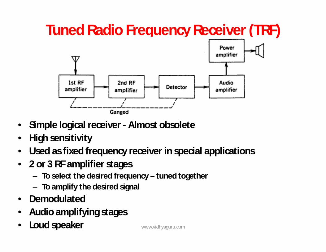
Tuned Radio Frequency Receiver (TRF)
• Simple logical receiver - Almost obsolete • High sensitivity • Used as fixed frequency receiver in special applications • 2 or 3 RF amplifier stages
– To select the desired frequency – tuned together – To amplify the desired signal
• Demodulated • Audio amplifying stages • Loud speaker www.vidhyaguru.com
Advantage • Simple to design and align at AM broadcast
frequencies (535KHz - 1640KHz) Drawbacks
1. Instability – associated with high gain being achieved at one frequency by multistage amplifier • Example – with a gain of 40000, a small fraction say
1/40000 of the output of the last stage may fed back to the input of the first stage and produce oscillations at the frequency at which the polarity of this spurious feedback is positive
• Unavoidable
www.vidhyaguru.com
2. Poor selectivity at high frequencies – because of single tuned circuits – difficult to use several double tuned amplifiers in unison
3. Bandwidth variation over the tuning range 4. Insufficient adjacent frequency rejection - For a BW of 10KHz – At the lower end of the band: Q=f/BW =
535/10 = 53.5. At the other end of the band: Q = 1640/10 = 164. – not possible to achieve. Practical value of Q=120; Now BW = 1640/120 = 13.7 KHz. ie. Receiver may pick up adjacent stations
- At 36.5 MHz; Q = 36500/10 = 3650 – impossible Note: Problems of instability, insufficient adjacent frequency
rejection and bandwidth variation are solved by the use of Super heterodyne receivers
www.vidhyaguru.com
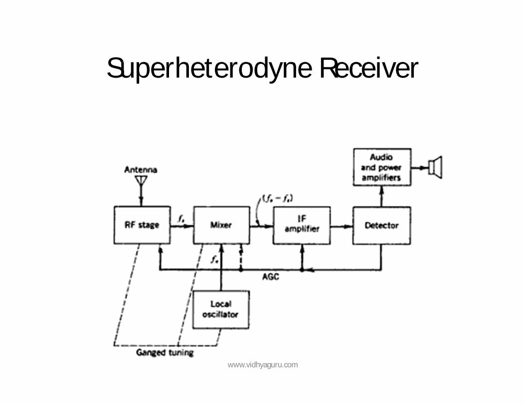
Superheterodyne Receiver
www.vidhyaguru.com
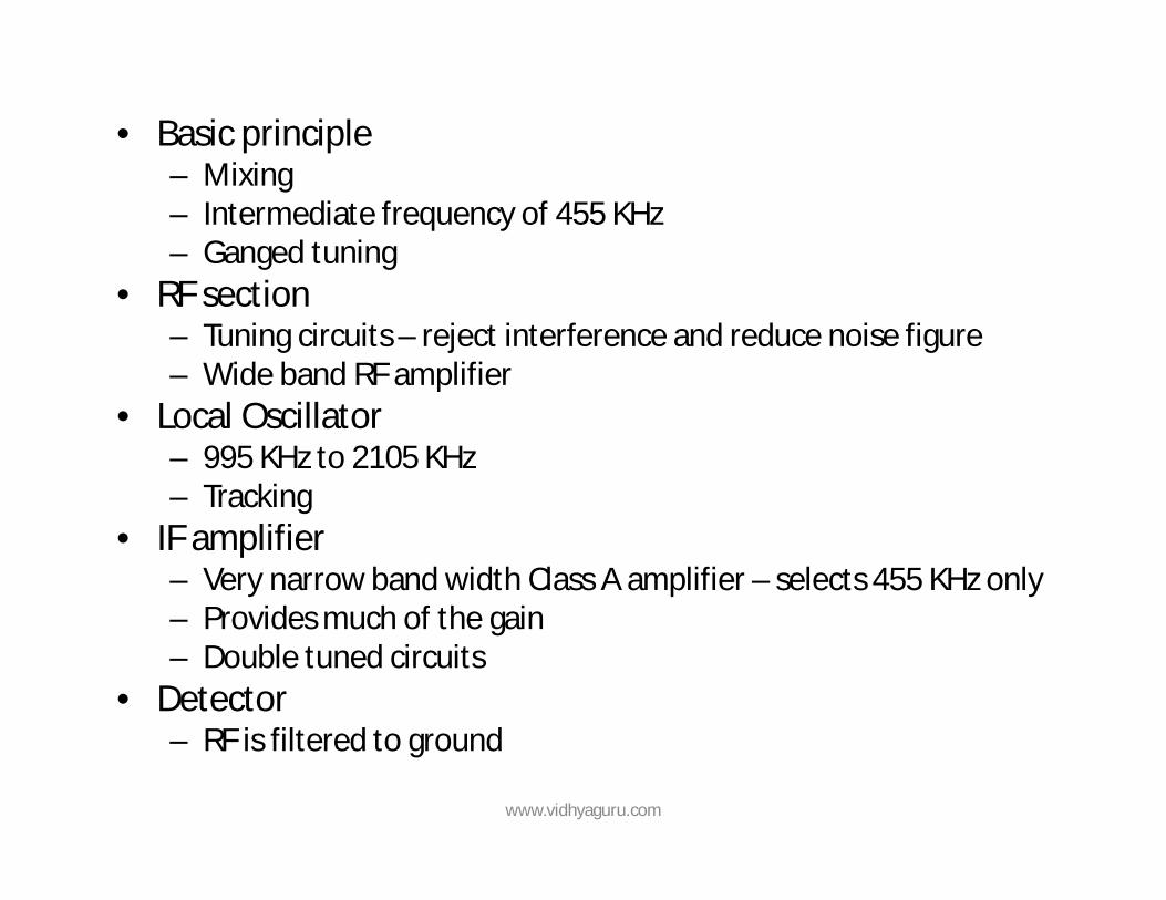
• Basic principle – Mixing – Intermediate frequency of 455 KHz – Ganged tuning
• RF section – Tuning circuits – reject interference and reduce noise figure – Wide band RF amplifier
• Local Oscillator – 995 KHz to 2105 KHz – Tracking
• IF amplifier – Very narrow band width Class A amplifier – selects 455 KHz only – Provides much of the gain – Double tuned circuits
• Detector – RF is filtered to ground
www.vidhyaguru.com
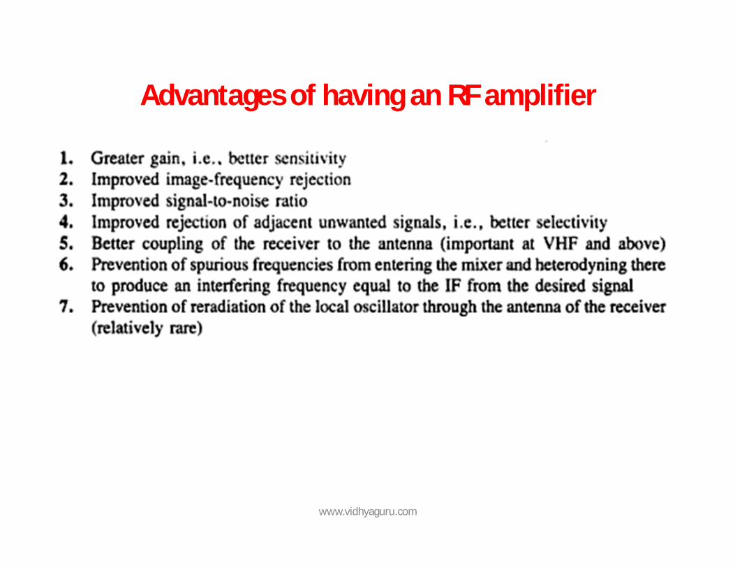
Advantages of having an RF amplifier
www.vidhyaguru.com
Sensitivity
• Ability to amplify weak signals • Defined as the voltage that must be applied to the
receiver input terminals to give a standard output power at the output terminals
• Standards followed to measure sensitivity – 30% modulation by a 400 Hz sine wave is used – Signal applied to the receiver through dummy antenna – Standard output is 50 mW – Loud speaker replaced by an equivalent load resistance – Expressed in microvolts (µV) – Measured at three points
• At 1000 KHz sensitivity = 12.7 µV
www.vidhyaguru.com
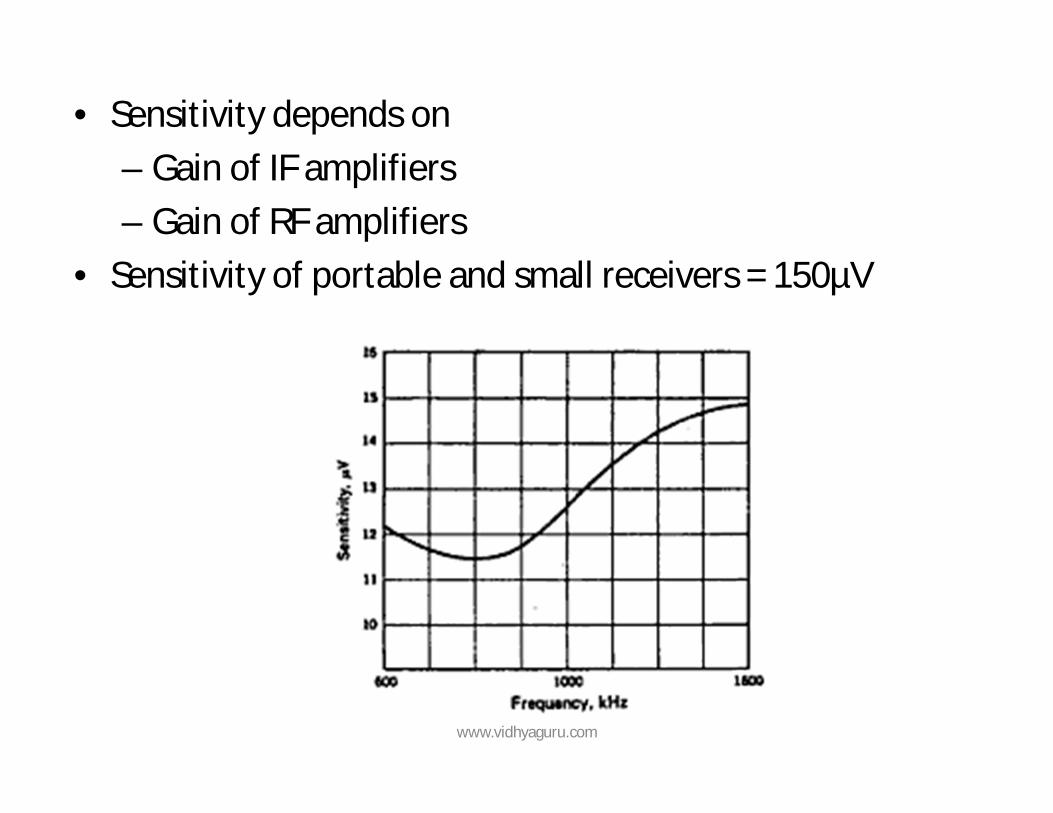
• Sensitivity depends on – Gain of IF amplifiers – Gain of RF amplifiers
• Sensitivity of portable and small receivers = 150µV
www.vidhyaguru.com
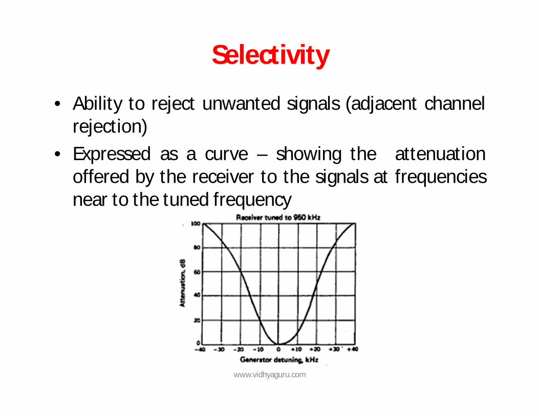
Selectivity
• Ability to reject unwanted signals (adjacent channel rejection)
• Expressed as a curve – showing the attenuation offered by the receiver to the signals at frequencies near to the tuned frequency
www.vidhyaguru.com
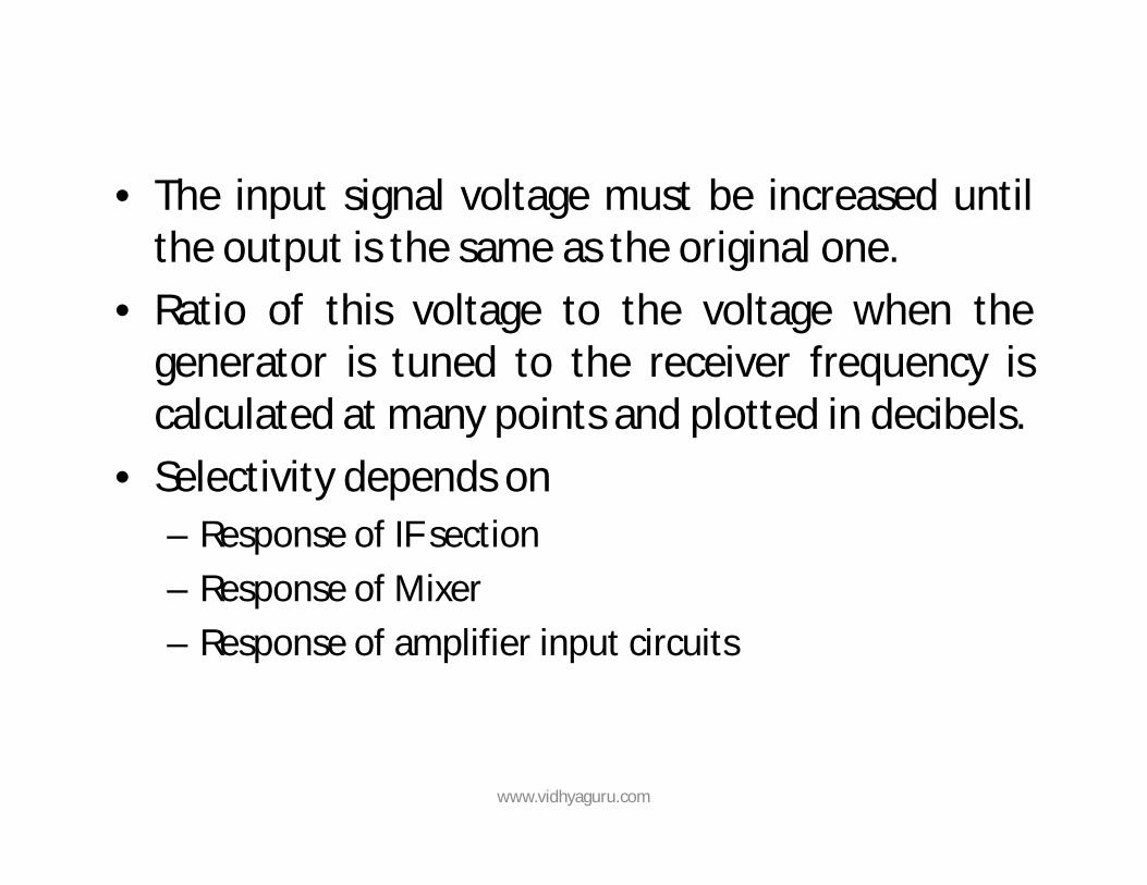
• The input signal voltage must be increased until the output is the same as the original one.
• Ratio of this voltage to the voltage when the generator is tuned to the receiver frequency is calculated at many points and plotted in decibels.
• Selectivity depends on – Response of IF section – Response of Mixer – Response of amplifier input circuits
www.vidhyaguru.com
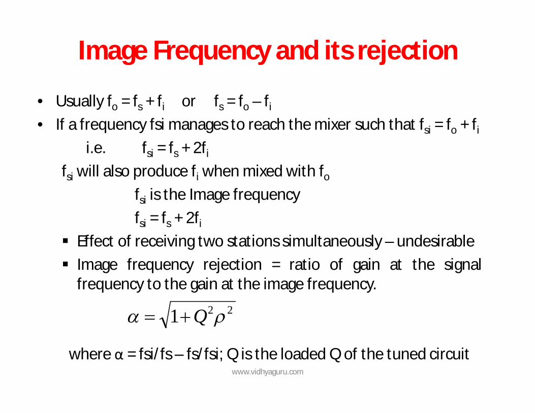
Image Frequency and its rejection
• Usually fo = fs + fi or fs = fo – fi
• If a frequency fsi manages to reach the mixer such that fsi = fo + fi
i.e. fsi = fs + 2fi
fsi will also produce fi when mixed with fo
fsi is the Image frequency fsi = fs + 2fi
Effect of receiving two stations simultaneously – undesirable Image frequency rejection = ratio of gain at the signal
frequency to the gain at the image frequency.
where α = fsi/fs – fs/fsi; Q is the loaded Q of the tuned circuit
221 Q
www.vidhyaguru.com
Adjacent Channel Selectivity (Double spotting)
• Refer notes
www.vidhyaguru.com
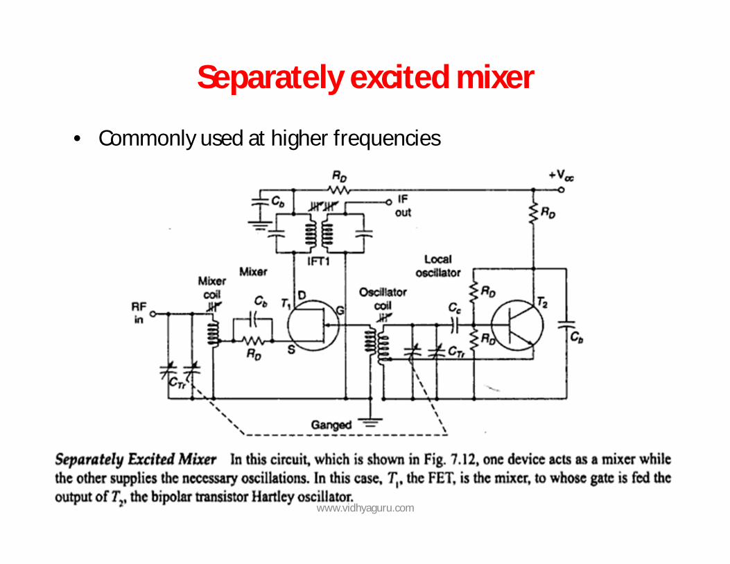
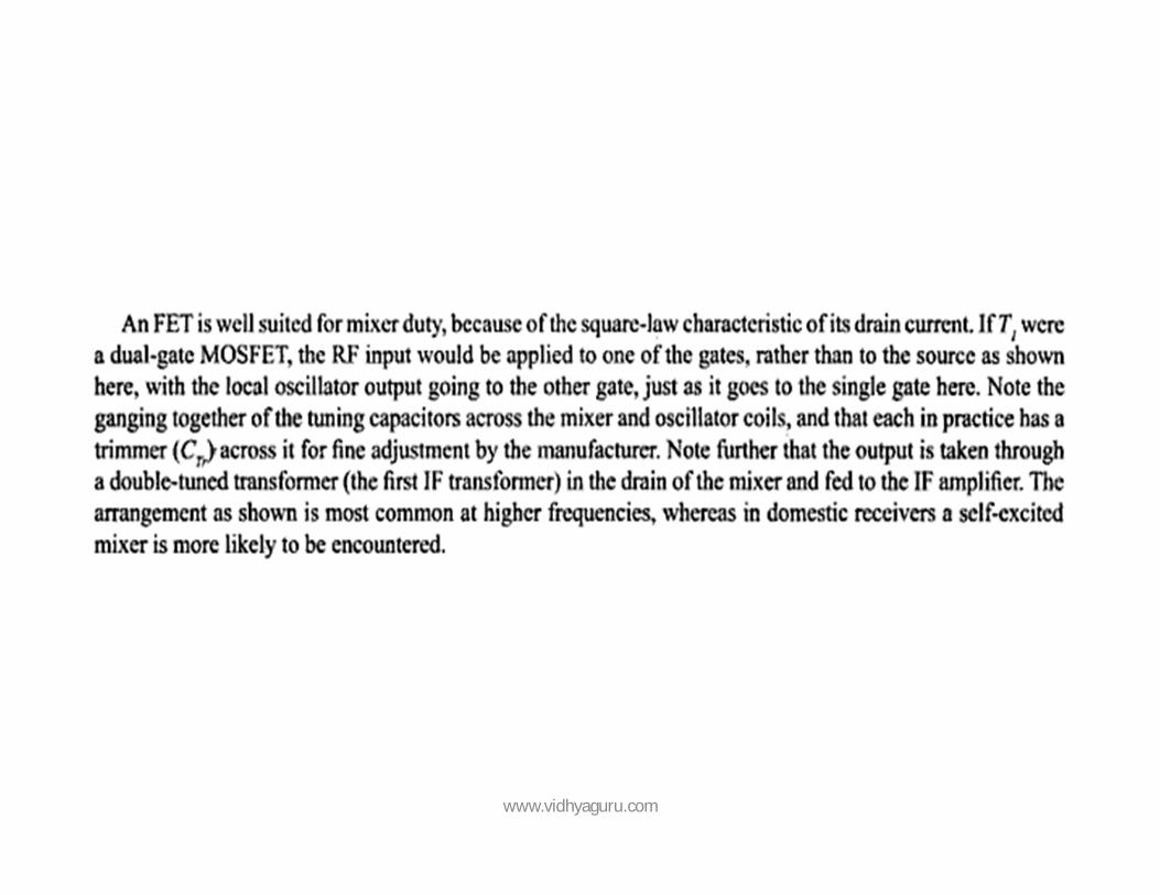
Separately excited mixer
• Commonly used at higher frequencies
www.vidhyaguru.com
www.vidhyaguru.com
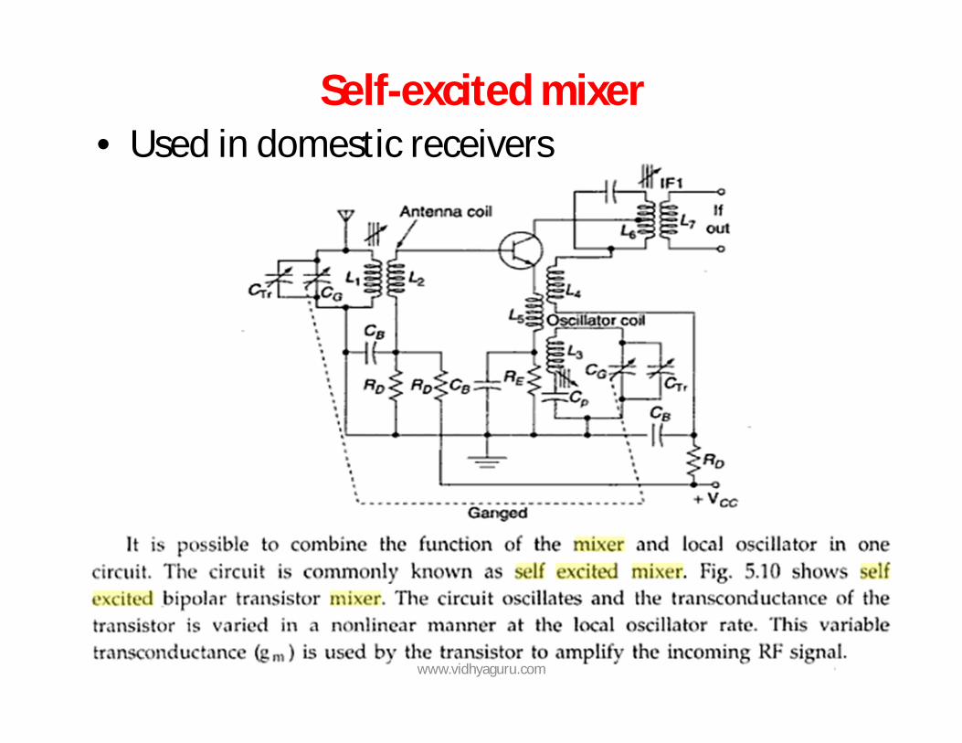
Self-excited mixer • Used in domestic receivers
www.vidhyaguru.com
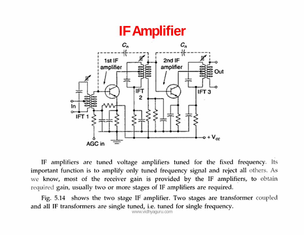
IF Amplifier
www.vidhyaguru.com
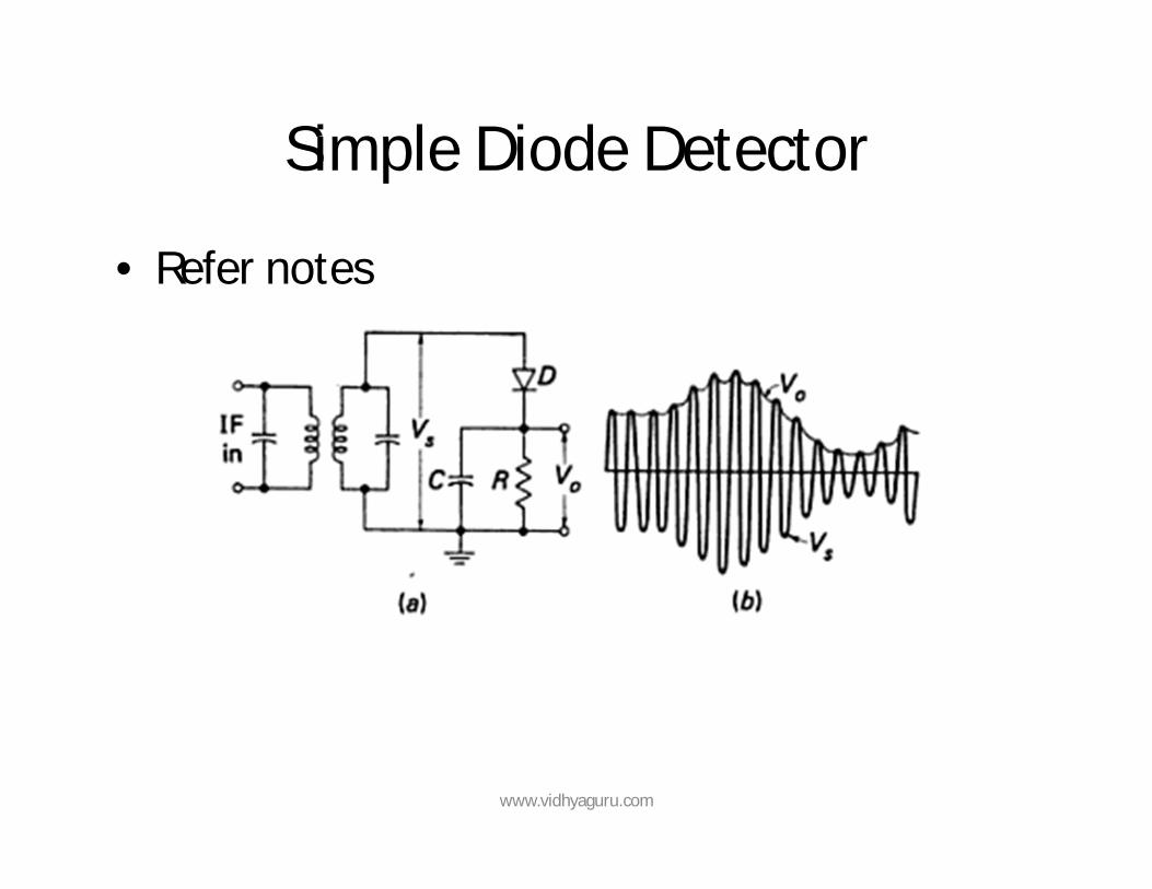
Simple Diode Detector
• Refer notes
www.vidhyaguru.com
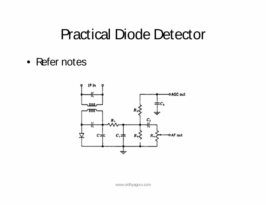
Practical Diode Detector
• Refer notes
www.vidhyaguru.com
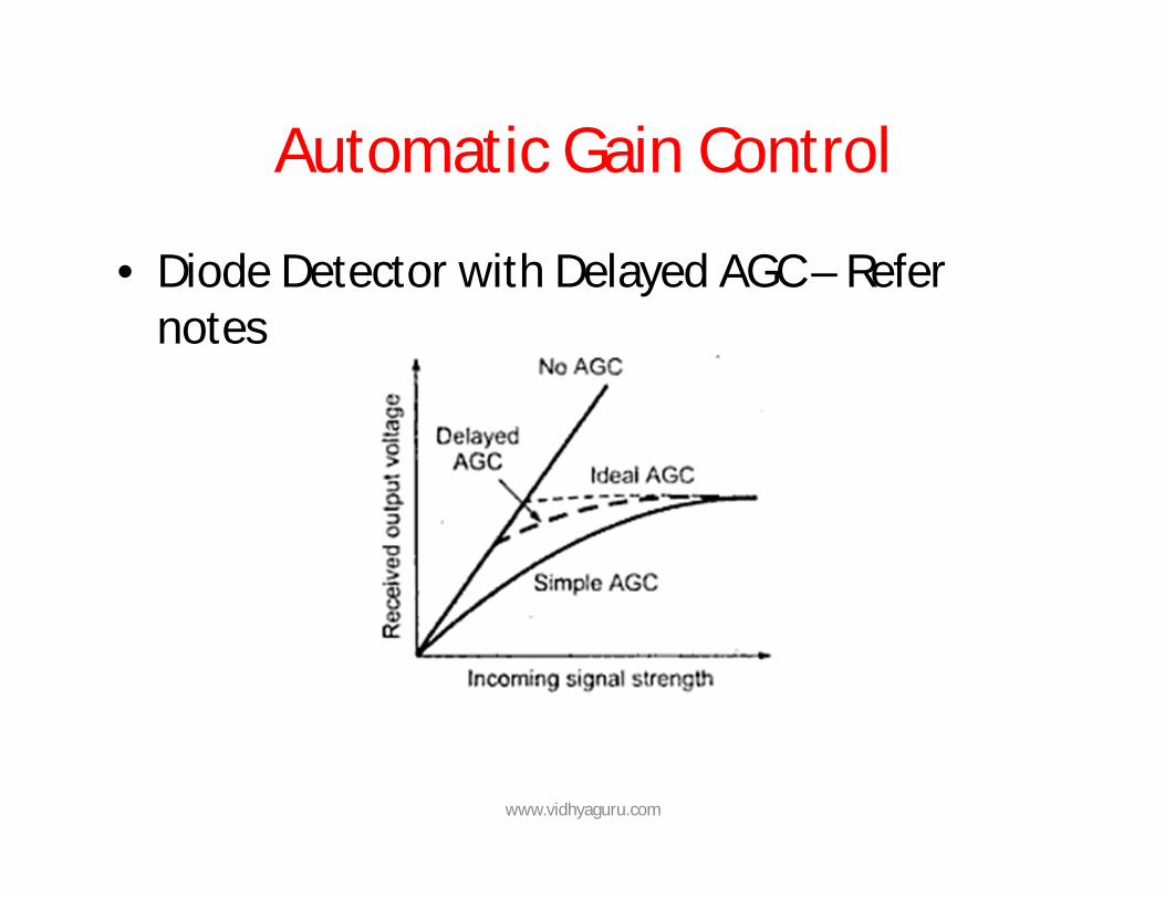
Automatic Gain Control
• Diode Detector with Delayed AGC – Refer notes
www.vidhyaguru.com
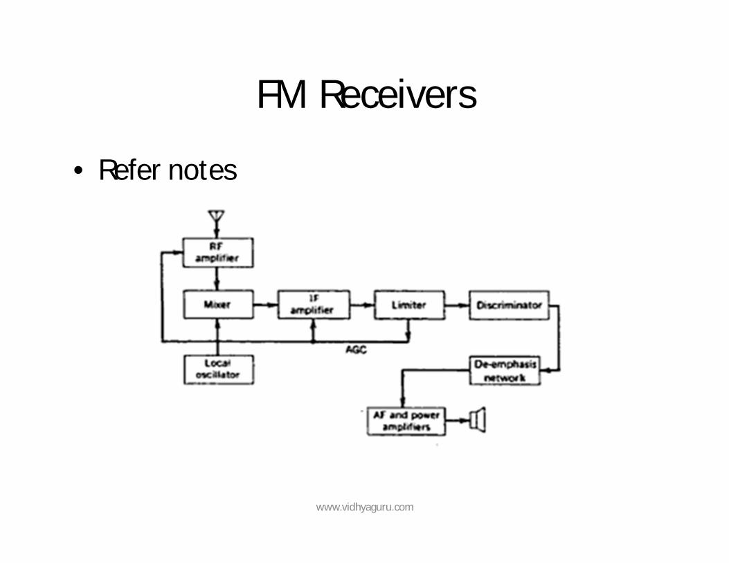
FM Receivers
• Refer notes
www.vidhyaguru.com
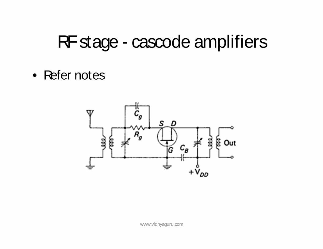
RF stage - cascode amplifiers
• Refer notes
www.vidhyaguru.com
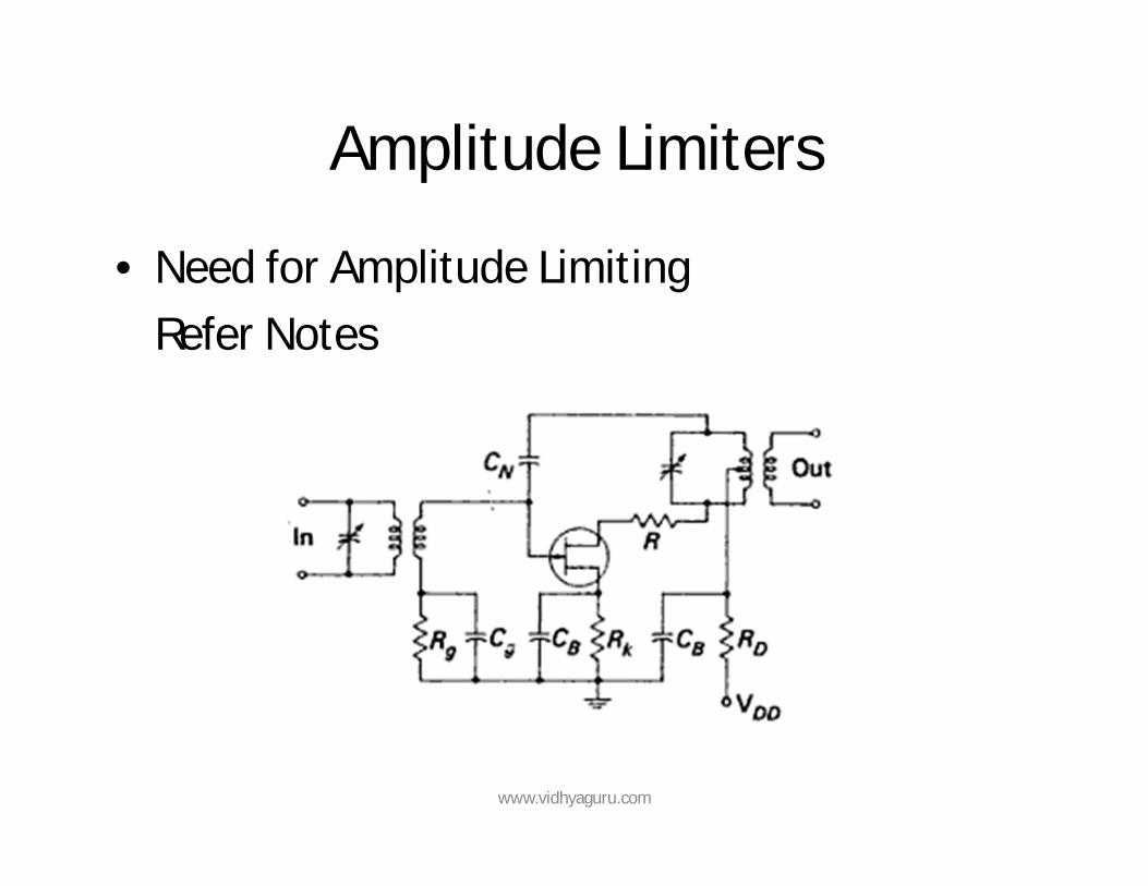
Amplitude Limiters
• Need for Amplitude Limiting Refer Notes
www.vidhyaguru.com
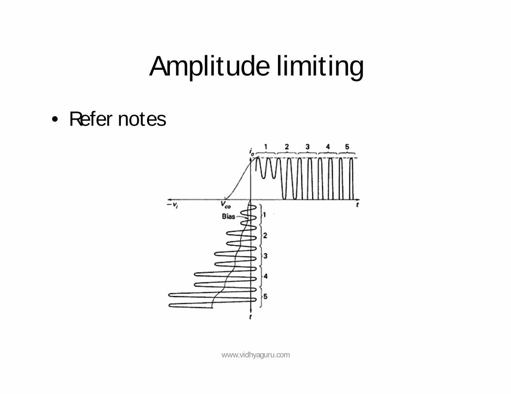
Amplitude limiting
• Refer notes
www.vidhyaguru.com
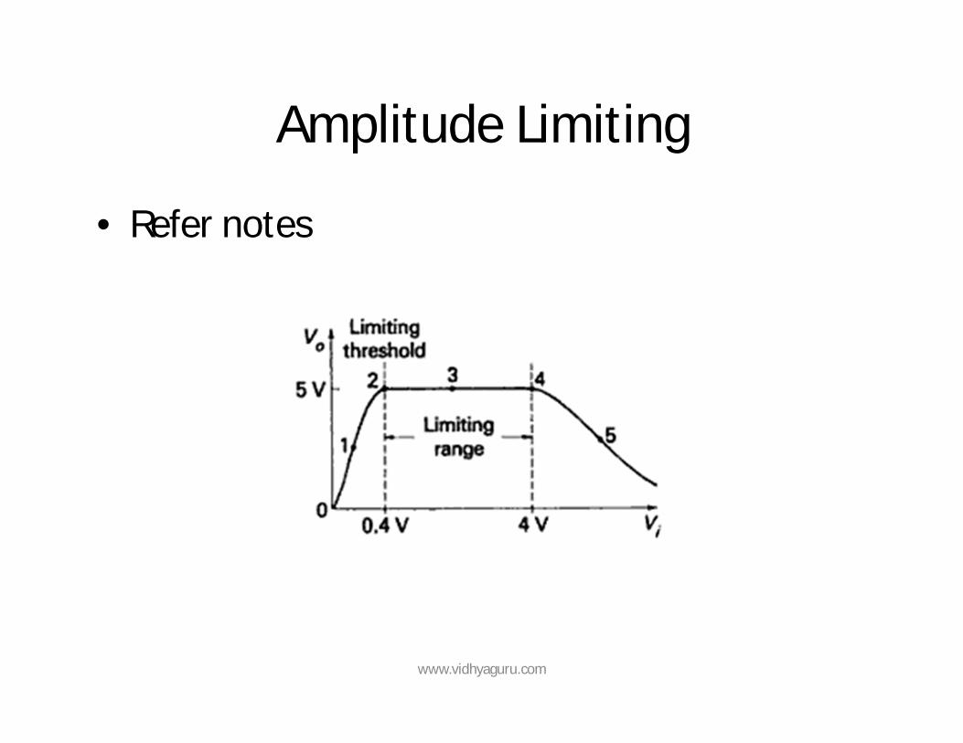
Amplitude Limiting
• Refer notes
www.vidhyaguru.com
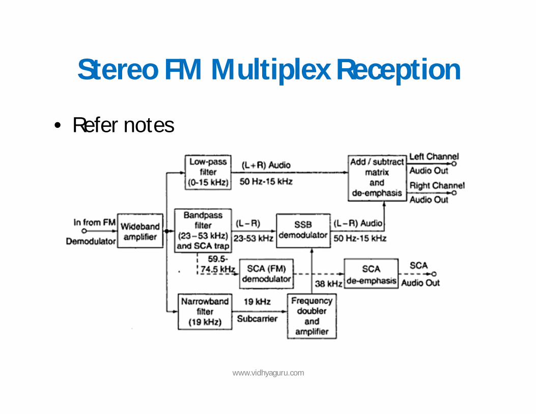
Stereo FM Multiplex Reception
• Refer notes
www.vidhyaguru.com