ignition of nanoparticles by a compact camera flash · is expected in the laser ignition of swnt5...
TRANSCRIPT
AFRL-RQ-ED-TR-2014-0029 Ignition of Nanoparticles by a Compact Camera Flash
Alireza Badakhshan Stephen Danczyk Air Force Research Laboratory (AFMC) AFRL/RQRC Combustion Devices Branch 10 E. Saturn Blvd. Edwards AFB CA 93524-7680 September 2014 In-House Interim Report
Distribution A: To be approved for Public Release; distribution unlimited. PA No. 15017
AIR FORCE RESEARCH LABORATORY AEROSPACE SYSTEMS DIRECTORATE
■ Air Force Materiel Command ■ United States Air Force ■ Edwards Air Force Base, CA 93524
STINFO COPY

--STINFO COPY--
NOTICE AND SIGNATURE PAGE Using Government drawings, specifications, or other data included in this document for any purpose other than Government procurement does not in any way obligate the U.S. Government. The fact that the Government formulated or supplied the drawings, specifications, or other data does not license the holder or any other person or corporation; or convey any rights or permission to manufacture, use, or sell any patented invention that may relate to them.
Qualified requestors may obtain copies of this report from the Defense Technical Information Center (DTIC) (http://www.dtic.mil). AFRL-RQ-ED-TR-2014-0029 HAS BEEN REVIEWED AND IS APPROVED FOR PUBLICATION IN ACCORDANCE WITH ASSIGNED DISTRIBUTION STATEMENT. FOR THE DIRECTOR: //Signed// //Signed// ______________________________________ _______________________________ STEPHEN A. DANCZYK, Ph.D. GREGORY A. RUDERMAN, Ph.D. Program Manager Technical Advisor
Combustion Devices Branch //Signed// ______________________________________ Technical Advisor Rocket Propulsion Division This report is published in the interest of scientific and technical information exchange, and its publication does not constitute the Government’s approval or disapproval of its ideas or findings.

REPORT DOCUMENTATION PAGE Form Approved
OMB No. 0704-0188 Public reporting burden for this collection of information is estimated to average 1 hour per response, including the time for reviewing instructions, searching existing data sources, gathering and maintaining the data needed, and completing and reviewing this collection of information. Send comments regarding this burden estimate or any other aspect of this collection of information, including suggestions for reducing this burden to Department of Defense, Washington Headquarters Services, Directorate for Information Operations and Reports (0704-0188), 1215 Jefferson Davis Highway, Suite 1204, Arlington, VA 22202-4302. Respondents should be aware that notwithstanding any other provision of law, no person shall be subject to any penalty for failing to comply with a collection of information if it does not display a currently valid OMB control number. PLEASE DO NOT RETURN YOUR FORM TO THE ABOVE ADDRESS.
1. REPORT DATE (DD-MM-YYYY) 21 September 2014
2. REPORT TYPEIn-House Interim Technical Report
3. DATES COVERED (From - To) 1 Jan 2014 - 23 Jun 2014
4. TITLE AND SUBTITLE Ignition of Nanoparticles by a Compact Camera Flash
5a. CONTRACT NUMBER
5b. GRANT NUMBER
5c. PROGRAM ELEMENT NUMBER 62102F
6. AUTHOR(S) Alireza Badakhshan; Stephen Danczyk
5d. PROJECT NUMBER
5e. TASK NUMBER
5f. WORK UNIT NUMBER Q0BL
7. PERFORMING ORGANIZATION NAME(S) AND ADDRESS(ES) 8. PERFORMING ORGANIZATION REPORT NO.
Air Force Research Laboratory (AFMC) AFRL/RQRC 4 Draco Drive Edwards AFB CA 93524-7160
9. SPONSORING / MONITORING AGENCY NAME(S) AND ADDRESS(ES) 10. SPONSOR/MONITOR’S ACRONYM(S) Air Force Research Laboratory (AFMC) AFRL/RQR 11. SPONSOR/MONITOR’S REPORT
5 Pollux Drive NUMBER(S)
Edwards AFB CA 93524-7048 AFRL-RQ-ED-TR-2014-0029
12. DISTRIBUTION / AVAILABILITY STATEMENT Approved for public release; distribution unlimited.
13. SUPPLEMENTARY NOTES PA No. 15017
14. ABSTRACT This report focuses on the measurement of MIE and the effects of certain key parameters on the ignition characteristics of the SWNT as well as some other nanoparticles. However, our main objective has been the identification of the most suitable nanoparticle for photoignition of fuel sprays for rocket applications.
15. SUBJECT TERMS
16. SECURITY CLASSIFICATION OF:
17. LIMITATION OF ABSTRACT
18. NUMBER OF PAGES
19a. NAME OF RESPONSIBLE PERSON
Dr. Stephen Danczyk
a. REPORT Unclassified
b. ABSTRACT Unclassified
c. THIS PAGE Unclassified
SAR 15 19b. TELEPHONE NO (include area code) N/A
Standard Form 298 (Rev. 8-98) Prescribed by ANSI Std. 239.18

This Page Intentionally Left Blank

i
Table of Contents
Introduction ................................................................................................................................................................... 1 Experimental Setup and Instrumentation ..................................................................................................................... 1 Experimental Procedure ................................................................................................................................................ 3 Experimental Results and Discussion ............................................................................................................................ 3 Photoignition of Different Nanostructured Materials ................................................................................................... 3 The Effect of Wavelength on Photoignition of SWNT ................................................................................................... 4 The Effect of Light Pulse Duration on the Photoignition of SWNT ................................................................................ 4 The Effect of Fe Content on Photoignition of CNTs ....................................................................................................... 6 Conclusions .................................................................................................................................................................... 6 Acknowledgements ....................................................................................................................................................... 7 References ..................................................................................................................................................................... 7 List of Symbols, Abbreviations, and Acronyms .............................................................................................................. 8
List of Figures
Figure 1 ‐ The experimental setup for the study of photoignition effect in SWNT. The digital camera and the fiber coupling for the spectrometer are not shown. ............................................................................................................. 2 Figure 2 ‐ The Xe‐flash pulse output for different power settings of a Canon 580 XE II camera flash as seen by the DET36A fast photodiode detector. M1/1 and M1/128 represents the highest and the lowest available setting for the light output respectively. ........................................................................................................................................ 5
List of Tables
Table 1 ‐ MIE for different nanostructured materials and their corresponding burn temperatures ............................ 3 Table 2 ‐ The MIE for SWNT samples at different pulse durations of the Xe‐flash of Figure 1 ..................................... 5 Table 3 ‐ MIE for SWNT samples with different Fe content in air. ................................................................................ 6
Approved for public release; distribution unlimited

This Page Intentionally Left Blank

1
Introduction
Ignition of dry single wall carbon nanotubes (SWNT) by a compact camera flash was first reported in 20011 and confirmed in other reports.2‐3 The presence of iron oxide particles in the combustion byproducts that were predominantly Fe2O3 with a small amount of Fe3O4 was also reported.
2 This phenomenon, known as photoignition, has not been reported for similar carbon rich materials such as graphite powder, carbon soot, activated charcoal and C60. The only exception is graphene oxide nanoplatelets, which show photoignition effect at a relatively high minimum ignition energy (MIE).4 Graphene nanoplatelets are unrolled form of carbon nanotube and they share the same SP2 bonding structure for carbon atoms.
For as‐grown (AG‐) SWNT samples and most other materials, photoignition is expected at an optical fluence (photon energy per unit area or radiant exposure) that is about two orders of magnitude lower than what is expected in the laser ignition of SWNT5 and other materials.6,7 SWNT are believed to provide a medium stabilizing the metal nanoparticles to prevent spontaneous initiation of ignition until they are exposed to a stimulating energy source such as illumination from a compact camera flash. It has been suggested that the nanotubes are damaged by exposure to light which provides the opportunity for the O2 atoms in the air to react with the pyrophoric Fe nanoparticles that are trapped inside SWNT
A recent work on the photoignition of graphene oxide suggests that presence of metal nanoparticles is not a necessity for inducing photoignition in all nanostructured materials. However, evidence of structural damage in nanostructure due to photon exposure were presented in this case.4 Nevertheless, the mechanism by which the flash either damages the SWNT structure thus exposing the Fe particles to the environmental oxygen as a result, or somehow it makes the Fe particles more reactive is unclear. There have been reports on the application of photoignition of SWNT as an ignition source for different materials including explosives8 and combustible gas mixtures.9 The work on the application of photoignition of nanotube for ignition of fuel spray in propulsion systems have been conducted at our lab and reported previously.10,11
This report focuses on the measurement of MIE and the effects of certain key parameters on the ignition characteristics of the SWNT as well as some other nanoparticles. However, our main objective has been the identification of the most suitable nanoparticle for photoignition of fuel sprays for rocket applications.
Experimental Setup and Instrumentation
The basic experimental setup consists of one or two identical camera flashes, Canon model 580 XEII, as
ignition light source, a pulse energy meter, from GenTec Corp., SUN series EM‐1 with ED‐500 detector head, and an XYZ linear translation stage with a filter wheel for introducing optical filters within the light path. The Canon camera flash consists of a compact Xe‐flash lamp with a variable 60‐5200 μs pulse duration that is provided through a 22‐ step energy setting via an electronic circuit. The light source was coupled to the sample area through a 3’x½” quartz fiber optic light guide from Sunoptics Technologies Corp., as shown in Figure 1.
The as‐grown (unpurified) SWNT samples were utilized for all of the reported results. These samples which were synthesized by the HiPco process were obtained from Unidym Corp, Houston, Texas. The carbon nanotubes in these samples are believed to be predominantly of single‐walled CNT, as stated by the vendor and they contain Fe nanoparticles and carbon impurities possibly in amorphous form. Therefore the term SWNT is used for the as‐grown SWNT samples for brevity throughout this paper. Otherwise it is stated that the sample was purified SWNT, i.e., the sample that was chemically treated to remove most of the impurities (predominantly Fe and carbon‐rich structures) from the sample.
In certain cases a double flash source was used, i.e. identical sources and camera flash hot‐shoes were utilized in order to ensure that the two flashes were triggered simultaneously, produced identical outputs, and worked in tandem. A third flash was used far away from the sample as a trigger, so that the two fiber coupled sources exhibited nearly perfect overlap in their temporal light output as verified by the temporal response of the photo detector. In this case a randomized bifurcated “Y” shaped fiber bundle was used to deliver the light from the two flashes to a single uniformly illuminated sample area as shown in Figure 1.
Approved for public release; distribution unlimited
2
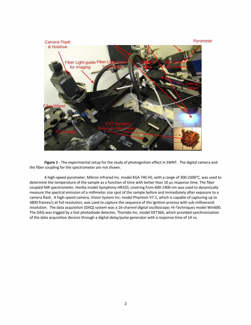
Figure 1 ‐ The experimental setup for the study of photoignition effect in SWNT. The digital camera and
the fiber coupling for the spectrometer are not shown. A high‐speed pyrometer, Mikron Infrared Inc. model KGA 740 HS, with a range of 300‐2300°C, was used to
determine the temperature of the sample as a function of time with better than 10 μs response time. The fiber coupled NIR spectrometer, Horiba model Symphony HR320, covering from 600‐1400 nm was used to dynamically measure the spectral emission of a millimeter size spot of the sample before and immediately after exposure to a camera flash. A high‐speed camera, Vision System Inc. model Phantom V7.1, which is capable of capturing up to 4800 frames/s at full resolution, was used to capture the sequence of the ignition process with sub millisecond resolution. The data acquisition (DAQ) system was a 16‐channel digital oscilloscope; Hi‐Techniques model Win600. The DAQ was trigged by a fast photodiode detector, Thorlabs Inc. model DET36A, which provided synchronization of the data acquisition devices through a digital delay/pulse generator with a response time of 14 ns.
CNT Samples Before & After Ignition
Camera Flash & Hotshoe
Filter Wheel
XYZ Stage
Energy Meter
Pyrometer
High Speed Video Camera
Sample Area
Fiber Light-guide for Imaging
Fiber Light-guide for Ignition

3
Experimental Procedure
Samples of different solid nanoparticles were placed on a glass slide and it was positioned within a few
millimeters below the output end of the fiber optic light guide as shown in Figure 1. The end of the fiber optic light guide near the sample was attached to a linear translation stage, so that it could be easily switched between the sample area and the detection head of the light pulse energy meter. This was to ensure that the dynamic measurements of the light from the camera flash truly reflected the energy output of the source as seen by the sample.
In order to provide a continuous adjustment of the optical fluence (energy per unit area), the input side of the fiber bundle light guide was held at a continuously adjustable distance from the camera flash through a linear translation stage. For each sample the preliminary measurement of the optical fluence leading to photoignition was initiated with a Xe‐flash energy well below MIE, which is defined as the lowest energy required for the initiation of the photoignition effect. The optical fluence on the sample was incrementally increased until the onset of the ignition was observed, i.e. MIE for the sample was determined. The energy per pulse was measured at each step and the sample was examined (in some cases through photographic images) before and after the application of each flash in order to verify the occurrence of photoignition. Photoignition of SWNT samples was usually indicated by photo‐induced oxidation of Fe nanoparticles in the sample. This was easily identifiable through change of color of the sample due to the formation of orange iron oxide on the surface of the sample.
Experimental Results and Discussion
The experimental setup shown in Figure 1 was used to investigate ignition characteristics of SWNT and a
number of other nanoparticles or nanostructured materials as revealed by their respected MIEs. For SWNT the study was expanded to include MIE as a function of the characteristics of the light source such as the wavelength and the Xe‐flash duration, as well as sample properties such as the compaction force and Fe content of CNT samples. Ignition characteristics of compacted SWNT samples were also studied in air and in an oxygen‐rich gas flow. Results for each of these studies are reported below.
Photoignition of Different Nanostructured Materials
The photoignition properties of SWNT were investigated with the setup of Figure 1 with a single or
double/tandem Canon 580 XII compact camera flashes. We also studied photoignition properties of other nanostructured materials such as multi‐walled CNT, C60 fullerenes and SWNTs from different vendors as well as carbon black, metallic and nonmetallic nano‐powders, and several ball milled metallic thermites. Table 1 only includes those materials that were better characterized and showed a more consistent photoignition (PI) effect. As seen from Table 1, SWNT samples with 51% Fe content exhibited the lowest MIE and aluminum nanoparticles exhibited the highest burn temperature.
Table 1 ‐ MIE for different nanostructured materials and their corresponding burn temperatures
Nanoparticle Samples Particle Size/Smallest
Dimensional size
Min. Ignition Energy/area, Fluence
(mJ/cm2)
Ignition/Burn Temperature* (⁰C)
SWNT(51% Fe) < 30 nm 64 ± 8 490 ± 30
SWNT(18% Fe) < 30 nm 182 ± 13 420 ± 50
Graphene Oxide Foam/Nanoplatelets
< 30 nm thick platelets
495 ± 60 370 ± 100
Al‐nanoparticles 18 nm 290 ± 50 1100 ± 150
Fe, , Carbon coated ~ 40 nm 220 ± 35 250 ± 30
Fe powder ~ 30 nm 150 ± 25 220 ± 30
Pd powder ~ 12 nm 530 ± 60 320 ± 40
*this is the temperature of a focused spot on the sample

4
The Effect of Wavelength on Photoignition of SWNT
The effect of the wavelength of light source on the photoignition of SWNT samples was investigated
within the spectral range of 300‐1600 nm. Different combinations of optical filters were utilized, including band pass, long pass, and short pass filters, in order to produce several spectral regions/bands covering the entire 300‐1600 nm spectral range. The typical spectral band‐pass regions for this study were between 250‐400 nm. The width of the band pass was dictated by the maximum light output through the filter set that was available to induce photoignition and to a lesser extent by the availability of the suitable optical filters. The highly desirable narrower spectral band pass filters were avoided because the optical fluence through such a band pass filter would be too low to induce photoignition in SWNT samples.
The study of wavelength effect on photoignition shows no particular spectral range within 300‐1600 nm that photoignition of SWNT samples are noticeably more sensitive to the wavelength of the light source. Based on the above, one may conclude that photoignition of SWNT is wavelength independent and most likely it is predominantly due to a highly efficient photothermal effect in nanostructured material. The main experimental limitation arises from the limited optical fluence output of the compact Canon 580 XEII Xe‐flash source, though it is among the highest available compact Xe‐flash sources with millisecond pulse duration.
The Effect of Light Pulse Duration on the Photoignition of SWNT
During the research of the ignition effect at different spectral regions we noticed that values of MIE for
identical samples were strongly influenced by the 22‐step output setting of the Xe‐flash. We initially associated the change in MIE with the wavelength of the light, only to be dismissed later, as an erroneous conclusion. However, a series of investigative measurements made it clear that the unexpected change in MIE was due to the pulse duration of the light source and not due to its wavelength. The measurements reveal that the light level setting of Canon 580‐XII Xe‐flash inadvertently changed the pulse duration of the light as well. This finding led to the study of the effect of pulse duration on photoignition that revealed important characteristics of the photoignition effect. In doing so we utilized the 22‐step power settings of Xe‐flash, which was associated with as many pulse flash duration selections. The eight primary settings of the Xe‐flash are shown in Figure 2 with two secondary settings in between the primary ones.
Figure 2 shows the light pulse output curves for a Canon 580‐XII Xe flash lamp, covering an estimated range of 60‐5200 μs for the “pulse duration.” Photoignition was induced in the SWNT samples with 43% and 51% Fe content for all but the lowest setting of the Xe flash lamp at and below M1/64 output setting of the Xe‐flash. The curves in Figure 2 are produced by the temporal response of the DET36A fast photodiode detector which has a response time of 14 ns. As shown in Figure 2, a higher light output is achieved merely through a longer lasting pulse, while the maximum pulse height remains the same. As such, at each setting the area under the curve best represents the output energy of the Xe‐flash. For photographic applications the timescale in Figure 2 is fast enough at any setting, but as we will describe later the pulse duration of the Xe‐flash has a noticeable effect on the photoignition response of the sample. It is worth mentioning that our effort in obtaining similar data from Canon Corp. was unsuccessful on the grounds that their pulse duration data was not available for public release.
Table 2 shows the minimum ignition energy as a function of pulse duration for SWNT sample with 43% Fe content. The fact that for any SWNT sample one is able to induce photoignition at a relatively lower fluence for shorter light pulse durations is an interesting property of the photoignition effect. In explaining the effect, it is important to note that the curves in Figure 2 are the “raw” data i.e. they are not normalized to the peak value, as it may appear from the curves. In considering the photoignition effect we are concerned with the optical fluence or radiant exposure in each case, i.e. the value that is directly correlated with the area under each light pulse output curve in Figure 2.

5
Figure 2 ‐ The Xe‐flash pulse output for different power settings of a Canon 580 XE II camera flash as seen
by the DET36A fast photodiode detector. M1/1 and M1/128 represents the highest and the lowest available setting for the light output respectively.
Table 2 ‐ The MIE for SWNT samples at different pulse durations of the Xe‐flash of Figure 1
Output Setting of Camera Flash
Estimated Pulse Duration*=A
(μs)
Area under Curve=B (a good measure of total light energy) (normalized to M1/32)
Relative Power=B/A
(a.u.)
Minimum Ignition Energy/Area (mJ/ cm2)
Canon M1/1 5200 13.5 2.6 68±7
Canon M1/2 1100 4.5 4.1 48±6
Canon M1/4 600 2.5 4.2 45±6
Canon M1/8 350 1.6 4.5 37±5
Canon M1/16 200 1.13 5.7 31±4
Canon M1/32 120 (normalized=1), 8.3 28±4
Canon M1/64 80 ~0.9 N/A no ignition
Canon M1/128 60 ~0.8 N/A no ignition
PerkinElmer CX‐1500
8‐10 (fixed) N/A N/A 26±3
*The estimated pulse duration is a rough measure of the pulse width of the curves in Figure 2.
6
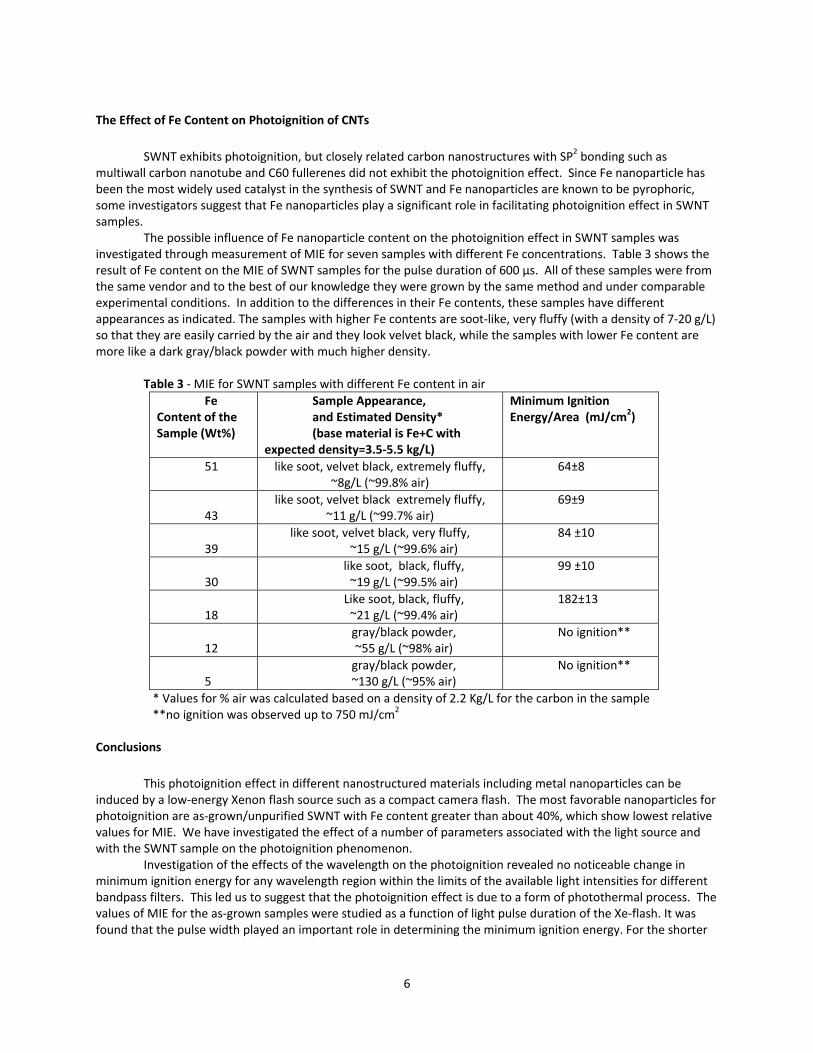
The Effect of Fe Content on Photoignition of CNTs
SWNT exhibits photoignition, but closely related carbon nanostructures with SP2 bonding such as
multiwall carbon nanotube and C60 fullerenes did not exhibit the photoignition effect. Since Fe nanoparticle has been the most widely used catalyst in the synthesis of SWNT and Fe nanoparticles are known to be pyrophoric, some investigators suggest that Fe nanoparticles play a significant role in facilitating photoignition effect in SWNT samples.
The possible influence of Fe nanoparticle content on the photoignition effect in SWNT samples was investigated through measurement of MIE for seven samples with different Fe concentrations. Table 3 shows the result of Fe content on the MIE of SWNT samples for the pulse duration of 600 µs. All of these samples were from the same vendor and to the best of our knowledge they were grown by the same method and under comparable experimental conditions. In addition to the differences in their Fe contents, these samples have different appearances as indicated. The samples with higher Fe contents are soot‐like, very fluffy (with a density of 7‐20 g/L) so that they are easily carried by the air and they look velvet black, while the samples with lower Fe content are more like a dark gray/black powder with much higher density.
Table 3 ‐ MIE for SWNT samples with different Fe content in air
Fe Content of the Sample (Wt%)
Sample Appearance, and Estimated Density* (base material is Fe+C with
expected density=3.5‐5.5 kg/L)
Minimum Ignition Energy/Area (mJ/cm2)
51 like soot, velvet black, extremely fluffy, ~8g/L (~99.8% air)
64±8
43 like soot, velvet black extremely fluffy,
~11 g/L (~99.7% air) 69±9
39 like soot, velvet black, very fluffy,
~15 g/L (~99.6% air) 84 ±10
30 like soot, black, fluffy,~19 g/L (~99.5% air)
99 ±10
18 Like soot, black, fluffy,~21 g/L (~99.4% air)
182±13
12 gray/black powder,~55 g/L (~98% air)
No ignition**
5 gray/black powder,~130 g/L (~95% air)
No ignition**
* Values for % air was calculated based on a density of 2.2 Kg/L for the carbon in the sample **no ignition was observed up to 750 mJ/cm2
Conclusions
This photoignition effect in different nanostructured materials including metal nanoparticles can be
induced by a low‐energy Xenon flash source such as a compact camera flash. The most favorable nanoparticles for photoignition are as‐grown/unpurified SWNT with Fe content greater than about 40%, which show lowest relative values for MIE. We have investigated the effect of a number of parameters associated with the light source and with the SWNT sample on the photoignition phenomenon.
Investigation of the effects of the wavelength on the photoignition revealed no noticeable change in minimum ignition energy for any wavelength region within the limits of the available light intensities for different bandpass filters. This led us to suggest that the photoignition effect is due to a form of photothermal process. The values of MIE for the as‐grown samples were studied as a function of light pulse duration of the Xe‐flash. It was found that the pulse width played an important role in determining the minimum ignition energy. For the shorter

7
light pulse duration a relatively lower MIE was observed for the SWNT samples as compared to longer pulse durations.
Acknowledgements
Funding support for this work was made possible by a grant from the Nanoscience and Technology
program of the Air Force Office of Scientific Research (AFOSR).
References
1. Ajayan, P.M., Terrones, M., de la Guardia, A., Huc, V., Grobert, N., Wei, B. Q., Lezec, H., Ramanath, G., and
Ebbesen, T. W., “Nanotubes in a Flash Ignition and Reconstruction,” Science Vol. 296, pp. 705, (2002). 2. Braidy, N., Botton, G. A., and Adronov, A., “Oxidation of Fe Nanoparticles Embedded in Single‐Walled
Carbon Nanotubes by Exposure to a Bright Flash of White Light,” Nanoletters Vol. 2 (11), pp 1277‐1280, (2002).
3. Smits, J., and Wincheski, B., “Response of Fe powder, purified and as‐produced HiPCo SWNT to flash exposure”, Materials Science and Engineering A, Vol. 358, (1‐2), pp. 384‐389, (2003).
4. Gilje, S., Dubin, S., Badakhshan, A., Farrar, J., Danczyk, S.A., Kaner, R.B., “Photothermal Deoxygenation of
Graphene Oxide to Graphitic Carbon for Distributed Ignition and Patterning Applications”, Advanced Materials Vol. 22 (3), pp 419–423, (2010).
5. Srikanth Singamaneni, Valeriy Shevchenko, Valery Bliznyuk, “Unusual ignition behavior of polyurethane/carbon nanotube composites with a He–Ne laser excitation (632.8 nm) during micro‐Raman spectroscopy”, Carbon, Vol. 44 (11), pp 2191–2195, (2006).
6. Abboud J., Jiang, N., Zhang, Z., Roy S., Gord, J.R., “Spatial and temporal control of on‐demand propane–air flame ignition by active photothermal effect of aluminum nanoenergetics”, Combustion and Flame Vol. 160 (9), pp 1842–1847, (2013).
7. Ostmark, H., Carlson, M., and Ekvall, K., “Laser ignition of explosives: Effects of laser wavelength on the threshold ignition energy”, J. Eng. Matt, Vol 12, pp 63‐83 (1994).
8. Manaa, R., Mitchell, A., and Garza, R., “Flash ignition and initiation of explosives−nanotubes mixture”, Journal of the American Chemical Society Vol. 127 (40), (2005).
9. A.M. Berkowitz and M.A. Oehlschlaeger, "The Photo‐Induced Ignition of Quiescent Ethylene/Air Mixtures Containing Suspended Carbon Nanotubes," Proceedings of the Combustion Institute, Vol. 33 (2), pp 3359‐3366, (2011).
10. Badakhshan, A., Danczyk, S.A., Wirth D., and Pilon, L., “Photo‐ignition of Liquid Fuel Spray by Carbon Nanotube Utilizing a Camera Flash,” Joint Army, Navy, NASA and Air Force Meeting 2011, Huntsville, AL, Dec. (2011).
11. Badakhshan, A., and Danczyk, S.A., “Photo‐ignition of Carbon Nanotube for Ignition of Liquid Fuel Spray and Solid Spray” TMS 2012, 141st Annual Meeting, Orlando, FL, Mar. (2012).
8
List of Symbols, Abbreviations, and Acronyms
DAQ data acquisition Fe iron MIE minimum ignition energy NIR near infrared nm nanometer ns nano second PI photoignition SWNT single wall carbon nanotube
AFRL-RQ-ED-TR-2014-0029 Primary Distribution of this Report:
RQR AFRL R&D Case Files Completed Interim and Final Tech Reports Repository
AFRL/RQ Technical Library (2 CD + 1 HC) 6 Draco Drive Edwards AFB CA 93524-7130
Chemical Propulsion Information Analysis Center Attn: Tech Lib (Mary Gannaway) (1 CD) 10630 Little Patuxent Parkway, Suite 202 Columbia MD 21044-3200
Defense Technical Information Center (1 Electronic Submission via STINT) Attn: DTIC-ACQS 8725 John J. Kingman Road, Suite 94 Ft. Belvoir VA 22060-6218